EP1833417B1 - Atraumatic stent with reduced deployment force and method for making the same - Google Patents
Atraumatic stent with reduced deployment force and method for making the same Download PDFInfo
- Publication number
- EP1833417B1 EP1833417B1 EP05825595A EP05825595A EP1833417B1 EP 1833417 B1 EP1833417 B1 EP 1833417B1 EP 05825595 A EP05825595 A EP 05825595A EP 05825595 A EP05825595 A EP 05825595A EP 1833417 B1 EP1833417 B1 EP 1833417B1
- Authority
- EP
- European Patent Office
- Prior art keywords
- wires
- stent
- securably
- regions
- wire
- Prior art date
- Legal status (The legal status is an assumption and is not a legal conclusion. Google has not performed a legal analysis and makes no representation as to the accuracy of the status listed.)
- Active
Links
- 238000000034 method Methods 0.000 title claims description 45
- 230000002829 reductive effect Effects 0.000 title description 3
- 239000000463 material Substances 0.000 claims abstract description 106
- BASFCYQUMIYNBI-UHFFFAOYSA-N platinum Chemical compound [Pt] BASFCYQUMIYNBI-UHFFFAOYSA-N 0.000 claims abstract description 50
- 229910052751 metal Inorganic materials 0.000 claims abstract description 35
- 239000002184 metal Substances 0.000 claims abstract description 35
- 229910001000 nickel titanium Inorganic materials 0.000 claims abstract description 33
- HLXZNVUGXRDIFK-UHFFFAOYSA-N nickel titanium Chemical compound [Ti].[Ti].[Ti].[Ti].[Ti].[Ti].[Ti].[Ti].[Ti].[Ti].[Ti].[Ni].[Ni].[Ni].[Ni].[Ni].[Ni].[Ni].[Ni].[Ni].[Ni].[Ni].[Ni].[Ni].[Ni] HLXZNVUGXRDIFK-UHFFFAOYSA-N 0.000 claims abstract description 33
- 229910052697 platinum Inorganic materials 0.000 claims abstract description 25
- KDLHZDBZIXYQEI-UHFFFAOYSA-N Palladium Chemical compound [Pd] KDLHZDBZIXYQEI-UHFFFAOYSA-N 0.000 claims abstract description 24
- TZCXTZWJZNENPQ-UHFFFAOYSA-L barium sulfate Chemical compound [Ba+2].[O-]S([O-])(=O)=O TZCXTZWJZNENPQ-UHFFFAOYSA-L 0.000 claims abstract description 24
- PCHJSUWPFVWCPO-UHFFFAOYSA-N gold Chemical compound [Au] PCHJSUWPFVWCPO-UHFFFAOYSA-N 0.000 claims abstract description 22
- 229910052737 gold Inorganic materials 0.000 claims abstract description 22
- 239000010931 gold Substances 0.000 claims abstract description 22
- 229910052715 tantalum Inorganic materials 0.000 claims abstract description 21
- GUVRBAGPIYLISA-UHFFFAOYSA-N tantalum atom Chemical compound [Ta] GUVRBAGPIYLISA-UHFFFAOYSA-N 0.000 claims abstract description 21
- 239000002131 composite material Substances 0.000 claims abstract description 19
- 238000003384 imaging method Methods 0.000 claims abstract description 16
- 229910052763 palladium Inorganic materials 0.000 claims abstract description 12
- 239000002245 particle Substances 0.000 claims abstract description 11
- ZONODCCBXBRQEZ-UHFFFAOYSA-N platinum tungsten Chemical compound [W].[Pt] ZONODCCBXBRQEZ-UHFFFAOYSA-N 0.000 claims abstract description 11
- HWLDNSXPUQTBOD-UHFFFAOYSA-N platinum-iridium alloy Chemical compound [Ir].[Pt] HWLDNSXPUQTBOD-UHFFFAOYSA-N 0.000 claims abstract description 11
- 229910052703 rhodium Inorganic materials 0.000 claims abstract description 11
- 239000010948 rhodium Substances 0.000 claims abstract description 11
- MHOVAHRLVXNVSD-UHFFFAOYSA-N rhodium atom Chemical compound [Rh] MHOVAHRLVXNVSD-UHFFFAOYSA-N 0.000 claims abstract description 11
- 238000003466 welding Methods 0.000 claims description 55
- -1 polypropylene Polymers 0.000 claims description 34
- 238000005304 joining Methods 0.000 claims description 23
- 229920001296 polysiloxane Polymers 0.000 claims description 17
- 238000009954 braiding Methods 0.000 claims description 12
- 229920000728 polyester Polymers 0.000 claims description 11
- 238000009499 grossing Methods 0.000 claims description 10
- 238000012800 visualization Methods 0.000 claims description 10
- 239000004698 Polyethylene Substances 0.000 claims description 8
- 239000004743 Polypropylene Substances 0.000 claims description 8
- 229920000295 expanded polytetrafluoroethylene Polymers 0.000 claims description 8
- 229920000573 polyethylene Polymers 0.000 claims description 8
- 229920001155 polypropylene Polymers 0.000 claims description 8
- 229920001343 polytetrafluoroethylene Polymers 0.000 claims description 8
- 229920002635 polyurethane Polymers 0.000 claims description 8
- 239000004814 polyurethane Substances 0.000 claims description 8
- 239000004810 polytetrafluoroethylene Substances 0.000 claims description 7
- 229920000417 polynaphthalene Polymers 0.000 claims description 6
- 239000003550 marker Substances 0.000 description 37
- XKRFYHLGVUSROY-UHFFFAOYSA-N Argon Chemical compound [Ar] XKRFYHLGVUSROY-UHFFFAOYSA-N 0.000 description 12
- 239000000560 biocompatible material Substances 0.000 description 11
- 229910000531 Co alloy Inorganic materials 0.000 description 9
- RTAQQCXQSZGOHL-UHFFFAOYSA-N Titanium Chemical compound [Ti] RTAQQCXQSZGOHL-UHFFFAOYSA-N 0.000 description 9
- 230000000750 progressive effect Effects 0.000 description 9
- 229910001220 stainless steel Inorganic materials 0.000 description 9
- 239000010936 titanium Substances 0.000 description 9
- 229910052719 titanium Inorganic materials 0.000 description 9
- 229910052758 niobium Inorganic materials 0.000 description 8
- 239000010955 niobium Substances 0.000 description 8
- GUCVJGMIXFAOAE-UHFFFAOYSA-N niobium atom Chemical compound [Nb] GUCVJGMIXFAOAE-UHFFFAOYSA-N 0.000 description 8
- 239000010935 stainless steel Substances 0.000 description 8
- 229910052786 argon Inorganic materials 0.000 description 6
- 239000011261 inert gas Substances 0.000 description 6
- WFKWXMTUELFFGS-UHFFFAOYSA-N tungsten Chemical compound [W] WFKWXMTUELFFGS-UHFFFAOYSA-N 0.000 description 5
- 229910052721 tungsten Inorganic materials 0.000 description 5
- 239000010937 tungsten Substances 0.000 description 5
- 238000004804 winding Methods 0.000 description 5
- XEEYBQQBJWHFJM-UHFFFAOYSA-N Iron Chemical compound [Fe] XEEYBQQBJWHFJM-UHFFFAOYSA-N 0.000 description 4
- PXHVJJICTQNCMI-UHFFFAOYSA-N Nickel Chemical compound [Ni] PXHVJJICTQNCMI-UHFFFAOYSA-N 0.000 description 4
- 229920001244 Poly(D,L-lactide) Polymers 0.000 description 4
- 238000010894 electron beam technology Methods 0.000 description 4
- 239000003102 growth factor Substances 0.000 description 4
- 238000009940 knitting Methods 0.000 description 4
- 150000002739 metals Chemical class 0.000 description 4
- 229920001432 poly(L-lactide) Polymers 0.000 description 4
- 230000002792 vascular Effects 0.000 description 4
- HTTJABKRGRZYRN-UHFFFAOYSA-N Heparin Chemical compound OC1C(NC(=O)C)C(O)OC(COS(O)(=O)=O)C1OC1C(OS(O)(=O)=O)C(O)C(OC2C(C(OS(O)(=O)=O)C(OC3C(C(O)C(O)C(O3)C(O)=O)OS(O)(=O)=O)C(CO)O2)NS(O)(=O)=O)C(C(O)=O)O1 HTTJABKRGRZYRN-UHFFFAOYSA-N 0.000 description 3
- 208000031481 Pathologic Constriction Diseases 0.000 description 3
- 239000011149 active material Substances 0.000 description 3
- 229910045601 alloy Inorganic materials 0.000 description 3
- 239000000956 alloy Substances 0.000 description 3
- 239000003146 anticoagulant agent Substances 0.000 description 3
- 210000003445 biliary tract Anatomy 0.000 description 3
- 210000004556 brain Anatomy 0.000 description 3
- 210000000621 bronchi Anatomy 0.000 description 3
- 210000001072 colon Anatomy 0.000 description 3
- 150000001875 compounds Chemical class 0.000 description 3
- 238000003618 dip coating Methods 0.000 description 3
- 210000003238 esophagus Anatomy 0.000 description 3
- 239000000945 filler Substances 0.000 description 3
- 238000010438 heat treatment Methods 0.000 description 3
- 239000003112 inhibitor Substances 0.000 description 3
- 238000002595 magnetic resonance imaging Methods 0.000 description 3
- 230000002093 peripheral effect Effects 0.000 description 3
- 229920001610 polycaprolactone Polymers 0.000 description 3
- 239000004632 polycaprolactone Substances 0.000 description 3
- 229920000139 polyethylene terephthalate Polymers 0.000 description 3
- 239000005020 polyethylene terephthalate Substances 0.000 description 3
- 229920000642 polymer Polymers 0.000 description 3
- 210000002307 prostate Anatomy 0.000 description 3
- 210000003437 trachea Anatomy 0.000 description 3
- 210000001635 urinary tract Anatomy 0.000 description 3
- 210000005166 vasculature Anatomy 0.000 description 3
- BSYNRYMUTXBXSQ-UHFFFAOYSA-N Aspirin Chemical compound CC(=O)OC1=CC=CC=C1C(O)=O BSYNRYMUTXBXSQ-UHFFFAOYSA-N 0.000 description 2
- 101710112752 Cytotoxin Proteins 0.000 description 2
- 229910052692 Dysprosium Inorganic materials 0.000 description 2
- 239000004812 Fluorinated ethylene propylene Substances 0.000 description 2
- 150000000921 Gadolinium Chemical class 0.000 description 2
- 229910052688 Gadolinium Inorganic materials 0.000 description 2
- 229940123011 Growth factor receptor antagonist Drugs 0.000 description 2
- 239000004952 Polyamide Substances 0.000 description 2
- 229920000331 Polyhydroxybutyrate Polymers 0.000 description 2
- 229960001138 acetylsalicylic acid Drugs 0.000 description 2
- 230000000702 anti-platelet effect Effects 0.000 description 2
- 230000001028 anti-proliverative effect Effects 0.000 description 2
- 239000004019 antithrombin Chemical class 0.000 description 2
- 230000001588 bifunctional effect Effects 0.000 description 2
- 239000000919 ceramic Substances 0.000 description 2
- 239000003795 chemical substances by application Substances 0.000 description 2
- 238000001723 curing Methods 0.000 description 2
- 231100000599 cytotoxic agent Toxicity 0.000 description 2
- 239000002619 cytotoxin Substances 0.000 description 2
- 229910003460 diamond Inorganic materials 0.000 description 2
- 239000010432 diamond Substances 0.000 description 2
- KBQHZAAAGSGFKK-UHFFFAOYSA-N dysprosium atom Chemical compound [Dy] KBQHZAAAGSGFKK-UHFFFAOYSA-N 0.000 description 2
- 229910000701 elgiloys (Co-Cr-Ni Alloy) Inorganic materials 0.000 description 2
- HQQADJVZYDDRJT-UHFFFAOYSA-N ethene;prop-1-ene Chemical group C=C.CC=C HQQADJVZYDDRJT-UHFFFAOYSA-N 0.000 description 2
- UIWYJDYFSGRHKR-UHFFFAOYSA-N gadolinium atom Chemical compound [Gd] UIWYJDYFSGRHKR-UHFFFAOYSA-N 0.000 description 2
- 239000007789 gas Substances 0.000 description 2
- 229960002897 heparin Drugs 0.000 description 2
- 229920000669 heparin Polymers 0.000 description 2
- 229910052742 iron Inorganic materials 0.000 description 2
- 230000000670 limiting effect Effects 0.000 description 2
- 229910052759 nickel Inorganic materials 0.000 description 2
- 210000000056 organ Anatomy 0.000 description 2
- 230000036961 partial effect Effects 0.000 description 2
- 229920009441 perflouroethylene propylene Polymers 0.000 description 2
- 238000009832 plasma treatment Methods 0.000 description 2
- 229920003023 plastic Polymers 0.000 description 2
- 239000004033 plastic Substances 0.000 description 2
- 229920001245 poly(D,L-lactide-co-caprolactone) Polymers 0.000 description 2
- 239000005015 poly(hydroxybutyrate) Substances 0.000 description 2
- 229920002647 polyamide Polymers 0.000 description 2
- 229920000570 polyether Polymers 0.000 description 2
- 239000000843 powder Substances 0.000 description 2
- 230000005855 radiation Effects 0.000 description 2
- 150000003839 salts Chemical class 0.000 description 2
- 230000001954 sterilising effect Effects 0.000 description 2
- 238000004659 sterilization and disinfection Methods 0.000 description 2
- 210000002784 stomach Anatomy 0.000 description 2
- 210000001519 tissue Anatomy 0.000 description 2
- 230000000472 traumatic effect Effects 0.000 description 2
- 210000005167 vascular cell Anatomy 0.000 description 2
- OQANPHBRHBJGNZ-FYJGNVAPSA-N (3e)-6-oxo-3-[[4-(pyridin-2-ylsulfamoyl)phenyl]hydrazinylidene]cyclohexa-1,4-diene-1-carboxylic acid Chemical compound C1=CC(=O)C(C(=O)O)=C\C1=N\NC1=CC=C(S(=O)(=O)NC=2N=CC=CC=2)C=C1 OQANPHBRHBJGNZ-FYJGNVAPSA-N 0.000 description 1
- PUDHBTGHUJUUFI-SCTWWAJVSA-N (4r,7s,10s,13r,16s,19r)-10-(4-aminobutyl)-n-[(2s,3r)-1-amino-3-hydroxy-1-oxobutan-2-yl]-19-[[(2r)-2-amino-3-naphthalen-2-ylpropanoyl]amino]-16-[(4-hydroxyphenyl)methyl]-13-(1h-indol-3-ylmethyl)-6,9,12,15,18-pentaoxo-7-propan-2-yl-1,2-dithia-5,8,11,14,17-p Chemical compound C([C@H]1C(=O)N[C@H](CC=2C3=CC=CC=C3NC=2)C(=O)N[C@@H](CCCCN)C(=O)N[C@H](C(N[C@@H](CSSC[C@@H](C(=O)N1)NC(=O)[C@H](N)CC=1C=C2C=CC=CC2=CC=1)C(=O)N[C@@H]([C@@H](C)O)C(N)=O)=O)C(C)C)C1=CC=C(O)C=C1 PUDHBTGHUJUUFI-SCTWWAJVSA-N 0.000 description 1
- ZKMNUMMKYBVTFN-HNNXBMFYSA-N (S)-ropivacaine Chemical compound CCCN1CCCC[C@H]1C(=O)NC1=C(C)C=CC=C1C ZKMNUMMKYBVTFN-HNNXBMFYSA-N 0.000 description 1
- SUNMBRGCANLOEG-UHFFFAOYSA-N 1,3-dichloroacetone Chemical compound ClCC(=O)CCl SUNMBRGCANLOEG-UHFFFAOYSA-N 0.000 description 1
- LEBVLXFERQHONN-UHFFFAOYSA-N 1-butyl-N-(2,6-dimethylphenyl)piperidine-2-carboxamide Chemical compound CCCCN1CCCCC1C(=O)NC1=C(C)C=CC=C1C LEBVLXFERQHONN-UHFFFAOYSA-N 0.000 description 1
- VNDNKFJKUBLYQB-UHFFFAOYSA-N 2-(4-amino-6-chloro-5-oxohexyl)guanidine Chemical compound ClCC(=O)C(N)CCCN=C(N)N VNDNKFJKUBLYQB-UHFFFAOYSA-N 0.000 description 1
- 102400000068 Angiostatin Human genes 0.000 description 1
- 108010079709 Angiostatins Proteins 0.000 description 1
- IYMAXBFPHPZYIK-BQBZGAKWSA-N Arg-Gly-Asp Chemical compound NC(N)=NCCC[C@H](N)C(=O)NCC(=O)N[C@@H](CC(O)=O)C(O)=O IYMAXBFPHPZYIK-BQBZGAKWSA-N 0.000 description 1
- VOVIALXJUBGFJZ-KWVAZRHASA-N Budesonide Chemical compound C1CC2=CC(=O)C=C[C@]2(C)[C@@H]2[C@@H]1[C@@H]1C[C@H]3OC(CCC)O[C@@]3(C(=O)CO)[C@@]1(C)C[C@@H]2O VOVIALXJUBGFJZ-KWVAZRHASA-N 0.000 description 1
- OKTJSMMVPCPJKN-UHFFFAOYSA-N Carbon Chemical compound [C] OKTJSMMVPCPJKN-UHFFFAOYSA-N 0.000 description 1
- 229920000049 Carbon (fiber) Polymers 0.000 description 1
- VYZAMTAEIAYCRO-UHFFFAOYSA-N Chromium Chemical compound [Cr] VYZAMTAEIAYCRO-UHFFFAOYSA-N 0.000 description 1
- RYGMFSIKBFXOCR-UHFFFAOYSA-N Copper Chemical compound [Cu] RYGMFSIKBFXOCR-UHFFFAOYSA-N 0.000 description 1
- OMFXVFTZEKFJBZ-UHFFFAOYSA-N Corticosterone Natural products O=C1CCC2(C)C3C(O)CC(C)(C(CC4)C(=O)CO)C4C3CCC2=C1 OMFXVFTZEKFJBZ-UHFFFAOYSA-N 0.000 description 1
- 102400001047 Endostatin Human genes 0.000 description 1
- 108010079505 Endostatins Proteins 0.000 description 1
- IAYPIBMASNFSPL-UHFFFAOYSA-N Ethylene oxide Chemical compound C1CO1 IAYPIBMASNFSPL-UHFFFAOYSA-N 0.000 description 1
- GHASVSINZRGABV-UHFFFAOYSA-N Fluorouracil Chemical compound FC1=CNC(=O)NC1=O GHASVSINZRGABV-UHFFFAOYSA-N 0.000 description 1
- 244000043261 Hevea brasiliensis Species 0.000 description 1
- 102000007625 Hirudins Human genes 0.000 description 1
- 108010007267 Hirudins Proteins 0.000 description 1
- UFHFLCQGNIYNRP-UHFFFAOYSA-N Hydrogen Chemical compound [H][H] UFHFLCQGNIYNRP-UHFFFAOYSA-N 0.000 description 1
- UETNIIAIRMUTSM-UHFFFAOYSA-N Jacareubin Natural products CC1(C)OC2=CC3Oc4c(O)c(O)ccc4C(=O)C3C(=C2C=C1)O UETNIIAIRMUTSM-UHFFFAOYSA-N 0.000 description 1
- ONIBWKKTOPOVIA-BYPYZUCNSA-N L-Proline Chemical compound OC(=O)[C@@H]1CCCN1 ONIBWKKTOPOVIA-BYPYZUCNSA-N 0.000 description 1
- NNJVILVZKWQKPM-UHFFFAOYSA-N Lidocaine Chemical compound CCN(CC)CC(=O)NC1=C(C)C=CC=C1C NNJVILVZKWQKPM-UHFFFAOYSA-N 0.000 description 1
- 229910019142 PO4 Inorganic materials 0.000 description 1
- 229930012538 Paclitaxel Natural products 0.000 description 1
- NTUPOKHATNSWCY-JYJNAYRXSA-N Phe-Pro-Arg Chemical compound C([C@H](N)C(=O)N1[C@@H](CCC1)C(=O)N[C@@H](CCCN=C(N)N)C(O)=O)C1=CC=CC=C1 NTUPOKHATNSWCY-JYJNAYRXSA-N 0.000 description 1
- 239000004696 Poly ether ether ketone Substances 0.000 description 1
- 229920001744 Polyaldehyde Polymers 0.000 description 1
- 239000004642 Polyimide Substances 0.000 description 1
- 239000004793 Polystyrene Substances 0.000 description 1
- 229920002396 Polyurea Polymers 0.000 description 1
- ONIBWKKTOPOVIA-UHFFFAOYSA-N Proline Natural products OC(=O)C1CCCN1 ONIBWKKTOPOVIA-UHFFFAOYSA-N 0.000 description 1
- 102000003990 Urokinase-type plasminogen activator Human genes 0.000 description 1
- 108090000435 Urokinase-type plasminogen activator Proteins 0.000 description 1
- JXLYSJRDGCGARV-WWYNWVTFSA-N Vinblastine Natural products O=C(O[C@H]1[C@](O)(C(=O)OC)[C@@H]2N(C)c3c(cc(c(OC)c3)[C@]3(C(=O)OC)c4[nH]c5c(c4CCN4C[C@](O)(CC)C[C@H](C3)C4)cccc5)[C@@]32[C@H]2[C@@]1(CC)C=CCN2CC3)C JXLYSJRDGCGARV-WWYNWVTFSA-N 0.000 description 1
- 238000004026 adhesive bonding Methods 0.000 description 1
- 229940121363 anti-inflammatory agent Drugs 0.000 description 1
- 239000002260 anti-inflammatory agent Substances 0.000 description 1
- 230000000118 anti-neoplastic effect Effects 0.000 description 1
- 239000003529 anticholesteremic agent Substances 0.000 description 1
- 229940127226 anticholesterol agent Drugs 0.000 description 1
- 229940127219 anticoagulant drug Drugs 0.000 description 1
- 108010072041 arginyl-glycyl-aspartic acid Proteins 0.000 description 1
- FZCSTZYAHCUGEM-UHFFFAOYSA-N aspergillomarasmine B Natural products OC(=O)CNC(C(O)=O)CNC(C(O)=O)CC(O)=O FZCSTZYAHCUGEM-UHFFFAOYSA-N 0.000 description 1
- 229910052788 barium Inorganic materials 0.000 description 1
- DSAJWYNOEDNPEQ-UHFFFAOYSA-N barium atom Chemical compound [Ba] DSAJWYNOEDNPEQ-UHFFFAOYSA-N 0.000 description 1
- 229910052797 bismuth Inorganic materials 0.000 description 1
- JCXGWMGPZLAOME-UHFFFAOYSA-N bismuth atom Chemical compound [Bi] JCXGWMGPZLAOME-UHFFFAOYSA-N 0.000 description 1
- 230000000903 blocking effect Effects 0.000 description 1
- 229960004436 budesonide Drugs 0.000 description 1
- 229960003150 bupivacaine Drugs 0.000 description 1
- 229910052799 carbon Inorganic materials 0.000 description 1
- 239000004917 carbon fiber Substances 0.000 description 1
- 230000010261 cell growth Effects 0.000 description 1
- 230000004663 cell proliferation Effects 0.000 description 1
- 239000007795 chemical reaction product Substances 0.000 description 1
- 229910052804 chromium Inorganic materials 0.000 description 1
- 239000011651 chromium Substances 0.000 description 1
- DQLATGHUWYMOKM-UHFFFAOYSA-L cisplatin Chemical compound N[Pt](N)(Cl)Cl DQLATGHUWYMOKM-UHFFFAOYSA-L 0.000 description 1
- 229960004316 cisplatin Drugs 0.000 description 1
- 229910017052 cobalt Inorganic materials 0.000 description 1
- 239000010941 cobalt Substances 0.000 description 1
- GUTLYIVDDKVIGB-UHFFFAOYSA-N cobalt atom Chemical compound [Co] GUTLYIVDDKVIGB-UHFFFAOYSA-N 0.000 description 1
- 230000006835 compression Effects 0.000 description 1
- 238000007906 compression Methods 0.000 description 1
- 239000000470 constituent Substances 0.000 description 1
- 230000008602 contraction Effects 0.000 description 1
- 238000001816 cooling Methods 0.000 description 1
- 229920001577 copolymer Polymers 0.000 description 1
- 229910052802 copper Inorganic materials 0.000 description 1
- 239000010949 copper Substances 0.000 description 1
- OMFXVFTZEKFJBZ-HJTSIMOOSA-N corticosterone Chemical compound O=C1CC[C@]2(C)[C@H]3[C@@H](O)C[C@](C)([C@H](CC4)C(=O)CO)[C@@H]4[C@@H]3CCC2=C1 OMFXVFTZEKFJBZ-HJTSIMOOSA-N 0.000 description 1
- NNBZCPXTIHJBJL-UHFFFAOYSA-N decalin Chemical compound C1CCCC2CCCCC21 NNBZCPXTIHJBJL-UHFFFAOYSA-N 0.000 description 1
- 230000001419 dependent effect Effects 0.000 description 1
- 229960003957 dexamethasone Drugs 0.000 description 1
- UREBDLICKHMUKA-CXSFZGCWSA-N dexamethasone Chemical compound C1CC2=CC(=O)C=C[C@]2(C)[C@]2(F)[C@@H]1[C@@H]1C[C@@H](C)[C@@](C(=O)CO)(O)[C@@]1(C)C[C@@H]2O UREBDLICKHMUKA-CXSFZGCWSA-N 0.000 description 1
- 229910003440 dysprosium oxide Inorganic materials 0.000 description 1
- NLQFUUYNQFMIJW-UHFFFAOYSA-N dysprosium(iii) oxide Chemical compound O=[Dy]O[Dy]=O NLQFUUYNQFMIJW-UHFFFAOYSA-N 0.000 description 1
- 230000002708 enhancing effect Effects 0.000 description 1
- 229930013356 epothilone Natural products 0.000 description 1
- HESCAJZNRMSMJG-KKQRBIROSA-N epothilone A Chemical class C/C([C@@H]1C[C@@H]2O[C@@H]2CCC[C@@H]([C@@H]([C@@H](C)C(=O)C(C)(C)[C@@H](O)CC(=O)O1)O)C)=C\C1=CSC(C)=N1 HESCAJZNRMSMJG-KKQRBIROSA-N 0.000 description 1
- 229940011871 estrogen Drugs 0.000 description 1
- 239000000262 estrogen Substances 0.000 description 1
- 238000009661 fatigue test Methods 0.000 description 1
- 230000005294 ferromagnetic effect Effects 0.000 description 1
- 239000000835 fiber Substances 0.000 description 1
- 239000003527 fibrinolytic agent Substances 0.000 description 1
- 229920002457 flexible plastic Polymers 0.000 description 1
- 238000002594 fluoroscopy Methods 0.000 description 1
- 229960002949 fluorouracil Drugs 0.000 description 1
- LGMLJQFQKXPRGA-VPVMAENOSA-K gadopentetate dimeglumine Chemical compound [Gd+3].CNC[C@H](O)[C@@H](O)[C@H](O)[C@H](O)CO.CNC[C@H](O)[C@@H](O)[C@H](O)[C@H](O)CO.OC(=O)CN(CC([O-])=O)CCN(CC([O-])=O)CCN(CC(O)=O)CC([O-])=O LGMLJQFQKXPRGA-VPVMAENOSA-K 0.000 description 1
- 229940044350 gadopentetate dimeglumine Drugs 0.000 description 1
- 239000003193 general anesthetic agent Substances 0.000 description 1
- 239000011521 glass Substances 0.000 description 1
- 239000003365 glass fiber Substances 0.000 description 1
- 239000002241 glass-ceramic Substances 0.000 description 1
- 239000003966 growth inhibitor Substances 0.000 description 1
- 239000001307 helium Substances 0.000 description 1
- 229910052734 helium Inorganic materials 0.000 description 1
- SWQJXJOGLNCZEY-UHFFFAOYSA-N helium atom Chemical compound [He] SWQJXJOGLNCZEY-UHFFFAOYSA-N 0.000 description 1
- 239000002628 heparin derivative Substances 0.000 description 1
- WQPDUTSPKFMPDP-OUMQNGNKSA-N hirudin Chemical compound C([C@@H](C(=O)N[C@@H](CCC(O)=O)C(=O)N[C@@H](CCC(O)=O)C(=O)N[C@@H]([C@@H](C)CC)C(=O)N1[C@@H](CCC1)C(=O)N[C@@H](CCC(O)=O)C(=O)N[C@@H](CCC(O)=O)C(=O)N[C@@H](CC=1C=CC(OS(O)(=O)=O)=CC=1)C(=O)N[C@@H](CC(C)C)C(=O)N[C@@H](CCC(N)=O)C(O)=O)NC(=O)[C@H](CC(O)=O)NC(=O)CNC(=O)[C@H](CC(O)=O)NC(=O)[C@H](CC(N)=O)NC(=O)[C@H](CC=1NC=NC=1)NC(=O)[C@H](CO)NC(=O)[C@H](CCC(N)=O)NC(=O)[C@H]1N(CCC1)C(=O)[C@H](CCCCN)NC(=O)[C@H]1N(CCC1)C(=O)[C@@H](NC(=O)CNC(=O)[C@H](CCC(O)=O)NC(=O)CNC(=O)[C@@H](NC(=O)[C@@H](NC(=O)[C@H]1NC(=O)[C@H](CCC(N)=O)NC(=O)[C@H](CC(N)=O)NC(=O)[C@H](CCCCN)NC(=O)[C@H](CCC(O)=O)NC(=O)CNC(=O)[C@H](CC(O)=O)NC(=O)[C@H](CO)NC(=O)CNC(=O)[C@H](CC(C)C)NC(=O)[C@H]([C@@H](C)CC)NC(=O)[C@@H]2CSSC[C@@H](C(=O)N[C@@H](CCC(O)=O)C(=O)NCC(=O)N[C@@H](CO)C(=O)N[C@@H](CC(N)=O)C(=O)N[C@H](C(=O)N[C@H](C(NCC(=O)N[C@@H](CCC(N)=O)C(=O)NCC(=O)N[C@@H](CC(N)=O)C(=O)N[C@@H](CCCCN)C(=O)N2)=O)CSSC1)C(C)C)NC(=O)[C@H](CC(C)C)NC(=O)[C@H]1NC(=O)[C@H](CC(C)C)NC(=O)[C@H](CC(N)=O)NC(=O)[C@H](CCC(N)=O)NC(=O)CNC(=O)[C@H](CO)NC(=O)[C@H](CCC(O)=O)NC(=O)[C@H]([C@@H](C)O)NC(=O)[C@@H](NC(=O)[C@H](CC(O)=O)NC(=O)[C@@H](NC(=O)[C@H](CC=2C=CC(O)=CC=2)NC(=O)[C@@H](NC(=O)[C@@H](N)C(C)C)C(C)C)[C@@H](C)O)CSSC1)C(C)C)[C@@H](C)O)[C@@H](C)O)C1=CC=CC=C1 WQPDUTSPKFMPDP-OUMQNGNKSA-N 0.000 description 1
- 229940006607 hirudin Drugs 0.000 description 1
- 239000001257 hydrogen Substances 0.000 description 1
- 229910052739 hydrogen Inorganic materials 0.000 description 1
- 238000001727 in vivo Methods 0.000 description 1
- 230000002401 inhibitory effect Effects 0.000 description 1
- 208000014674 injury Diseases 0.000 description 1
- 230000003993 interaction Effects 0.000 description 1
- 229910052741 iridium Inorganic materials 0.000 description 1
- GKOZUEZYRPOHIO-UHFFFAOYSA-N iridium atom Chemical compound [Ir] GKOZUEZYRPOHIO-UHFFFAOYSA-N 0.000 description 1
- 108010021336 lanreotide Proteins 0.000 description 1
- 229960002437 lanreotide Drugs 0.000 description 1
- 229960004194 lidocaine Drugs 0.000 description 1
- 238000013035 low temperature curing Methods 0.000 description 1
- 230000005291 magnetic effect Effects 0.000 description 1
- WPBNNNQJVZRUHP-UHFFFAOYSA-L manganese(2+);methyl n-[[2-(methoxycarbonylcarbamothioylamino)phenyl]carbamothioyl]carbamate;n-[2-(sulfidocarbothioylamino)ethyl]carbamodithioate Chemical compound [Mn+2].[S-]C(=S)NCCNC([S-])=S.COC(=O)NC(=S)NC1=CC=CC=C1NC(=S)NC(=O)OC WPBNNNQJVZRUHP-UHFFFAOYSA-L 0.000 description 1
- 229910000734 martensite Inorganic materials 0.000 description 1
- 230000007246 mechanism Effects 0.000 description 1
- 239000000155 melt Substances 0.000 description 1
- KBOPZPXVLCULAV-UHFFFAOYSA-N mesalamine Chemical compound NC1=CC=C(O)C(C(O)=O)=C1 KBOPZPXVLCULAV-UHFFFAOYSA-N 0.000 description 1
- 229960004963 mesalazine Drugs 0.000 description 1
- 239000002923 metal particle Substances 0.000 description 1
- 239000003604 miotic agent Substances 0.000 description 1
- 239000000203 mixture Substances 0.000 description 1
- 125000005487 naphthalate group Chemical group 0.000 description 1
- KYTZHLUVELPASH-UHFFFAOYSA-N naphthalene-1,2-dicarboxylic acid Chemical class C1=CC=CC2=C(C(O)=O)C(C(=O)O)=CC=C21 KYTZHLUVELPASH-UHFFFAOYSA-N 0.000 description 1
- 229920003052 natural elastomer Polymers 0.000 description 1
- 229920001194 natural rubber Polymers 0.000 description 1
- 229960001592 paclitaxel Drugs 0.000 description 1
- 230000005298 paramagnetic effect Effects 0.000 description 1
- 239000010452 phosphate Substances 0.000 description 1
- 239000000106 platelet aggregation inhibitor Substances 0.000 description 1
- 229920006209 poly(L-lactide-co-D,L-lactide) Polymers 0.000 description 1
- 229920003207 poly(ethylene-2,6-naphthalate) Polymers 0.000 description 1
- 229920006210 poly(glycolide-co-caprolactone) Polymers 0.000 description 1
- 229920002463 poly(p-dioxanone) polymer Polymers 0.000 description 1
- 229920002627 poly(phosphazenes) Polymers 0.000 description 1
- 239000004417 polycarbonate Substances 0.000 description 1
- 229920000515 polycarbonate Polymers 0.000 description 1
- 239000000622 polydioxanone Substances 0.000 description 1
- 229920002530 polyetherether ketone Polymers 0.000 description 1
- 239000011112 polyethylene naphthalate Substances 0.000 description 1
- 229920002643 polyglutamic acid Polymers 0.000 description 1
- 229920001721 polyimide Polymers 0.000 description 1
- 229920000098 polyolefin Polymers 0.000 description 1
- 229920002223 polystyrene Polymers 0.000 description 1
- 229920002689 polyvinyl acetate Polymers 0.000 description 1
- 239000011118 polyvinyl acetate Substances 0.000 description 1
- 239000004800 polyvinyl chloride Substances 0.000 description 1
- 229920000915 polyvinyl chloride Polymers 0.000 description 1
- 229960005205 prednisolone Drugs 0.000 description 1
- OIGNJSKKLXVSLS-VWUMJDOOSA-N prednisolone Chemical compound O=C1C=C[C@]2(C)[C@H]3[C@@H](O)C[C@](C)([C@@](CC4)(O)C(=O)CO)[C@@H]4[C@@H]3CCC2=C1 OIGNJSKKLXVSLS-VWUMJDOOSA-N 0.000 description 1
- 108090000765 processed proteins & peptides Proteins 0.000 description 1
- 102000004196 processed proteins & peptides Human genes 0.000 description 1
- 239000002089 prostaglandin antagonist Substances 0.000 description 1
- 229940044551 receptor antagonist Drugs 0.000 description 1
- 239000002464 receptor antagonist Substances 0.000 description 1
- 102000005962 receptors Human genes 0.000 description 1
- 108020003175 receptors Proteins 0.000 description 1
- 230000010076 replication Effects 0.000 description 1
- 230000000452 restraining effect Effects 0.000 description 1
- 229960001549 ropivacaine Drugs 0.000 description 1
- 238000007493 shaping process Methods 0.000 description 1
- 239000004447 silicone coating Substances 0.000 description 1
- 229920006268 silicone film Polymers 0.000 description 1
- 229920002379 silicone rubber Polymers 0.000 description 1
- 210000000329 smooth muscle myocyte Anatomy 0.000 description 1
- 238000005507 spraying Methods 0.000 description 1
- 238000003860 storage Methods 0.000 description 1
- 229920003048 styrene butadiene rubber Polymers 0.000 description 1
- 229960001940 sulfasalazine Drugs 0.000 description 1
- NCEXYHBECQHGNR-UHFFFAOYSA-N sulfasalazine Natural products C1=C(O)C(C(=O)O)=CC(N=NC=2C=CC(=CC=2)S(=O)(=O)NC=2N=CC=CC=2)=C1 NCEXYHBECQHGNR-UHFFFAOYSA-N 0.000 description 1
- RCINICONZNJXQF-MZXODVADSA-N taxol Chemical compound O([C@@H]1[C@@]2(C[C@@H](C(C)=C(C2(C)C)[C@H](C([C@]2(C)[C@@H](O)C[C@H]3OC[C@]3([C@H]21)OC(C)=O)=O)OC(=O)C)OC(=O)[C@H](O)[C@@H](NC(=O)C=1C=CC=CC=1)C=1C=CC=CC=1)O)C(=O)C1=CC=CC=C1 RCINICONZNJXQF-MZXODVADSA-N 0.000 description 1
- 239000004753 textile Substances 0.000 description 1
- 239000003803 thymidine kinase inhibitor Substances 0.000 description 1
- 108091006106 transcriptional activators Proteins 0.000 description 1
- 108091006107 transcriptional repressors Proteins 0.000 description 1
- 230000008733 trauma Effects 0.000 description 1
- 238000002604 ultrasonography Methods 0.000 description 1
- 229960005356 urokinase Drugs 0.000 description 1
- 239000003071 vasodilator agent Substances 0.000 description 1
- 229960003048 vinblastine Drugs 0.000 description 1
- JXLYSJRDGCGARV-XQKSVPLYSA-N vincaleukoblastine Chemical compound C([C@@H](C[C@]1(C(=O)OC)C=2C(=CC3=C([C@]45[C@H]([C@@]([C@H](OC(C)=O)[C@]6(CC)C=CCN([C@H]56)CC4)(O)C(=O)OC)N3C)C=2)OC)C[C@@](C2)(O)CC)N2CCC2=C1NC1=CC=CC=C21 JXLYSJRDGCGARV-XQKSVPLYSA-N 0.000 description 1
- 229960004528 vincristine Drugs 0.000 description 1
- OGWKCGZFUXNPDA-XQKSVPLYSA-N vincristine Chemical compound C([N@]1C[C@@H](C[C@]2(C(=O)OC)C=3C(=CC4=C([C@]56[C@H]([C@@]([C@H](OC(C)=O)[C@]7(CC)C=CCN([C@H]67)CC5)(O)C(=O)OC)N4C=O)C=3)OC)C[C@@](C1)(O)CC)CC1=C2NC2=CC=CC=C12 OGWKCGZFUXNPDA-XQKSVPLYSA-N 0.000 description 1
- OGWKCGZFUXNPDA-UHFFFAOYSA-N vincristine Natural products C1C(CC)(O)CC(CC2(C(=O)OC)C=3C(=CC4=C(C56C(C(C(OC(C)=O)C7(CC)C=CCN(C67)CC5)(O)C(=O)OC)N4C=O)C=3)OC)CN1CCC1=C2NC2=CC=CC=C12 OGWKCGZFUXNPDA-UHFFFAOYSA-N 0.000 description 1
- 229920002554 vinyl polymer Polymers 0.000 description 1
- 238000007794 visualization technique Methods 0.000 description 1
Images


Classifications
-
- A—HUMAN NECESSITIES
- A61—MEDICAL OR VETERINARY SCIENCE; HYGIENE
- A61F—FILTERS IMPLANTABLE INTO BLOOD VESSELS; PROSTHESES; DEVICES PROVIDING PATENCY TO, OR PREVENTING COLLAPSING OF, TUBULAR STRUCTURES OF THE BODY, e.g. STENTS; ORTHOPAEDIC, NURSING OR CONTRACEPTIVE DEVICES; FOMENTATION; TREATMENT OR PROTECTION OF EYES OR EARS; BANDAGES, DRESSINGS OR ABSORBENT PADS; FIRST-AID KITS
- A61F2/00—Filters implantable into blood vessels; Prostheses, i.e. artificial substitutes or replacements for parts of the body; Appliances for connecting them with the body; Devices providing patency to, or preventing collapsing of, tubular structures of the body, e.g. stents
- A61F2/82—Devices providing patency to, or preventing collapsing of, tubular structures of the body, e.g. stents
- A61F2/86—Stents in a form characterised by the wire-like elements; Stents in the form characterised by a net-like or mesh-like structure
- A61F2/90—Stents in a form characterised by the wire-like elements; Stents in the form characterised by a net-like or mesh-like structure characterised by a net-like or mesh-like structure
-
- D—TEXTILES; PAPER
- D04—BRAIDING; LACE-MAKING; KNITTING; TRIMMINGS; NON-WOVEN FABRICS
- D04C—BRAIDING OR MANUFACTURE OF LACE, INCLUDING BOBBIN-NET OR CARBONISED LACE; BRAIDING MACHINES; BRAID; LACE
- D04C1/00—Braid or lace, e.g. pillow-lace; Processes for the manufacture thereof
- D04C1/02—Braid or lace, e.g. pillow-lace; Processes for the manufacture thereof made from particular materials
-
- D—TEXTILES; PAPER
- D04—BRAIDING; LACE-MAKING; KNITTING; TRIMMINGS; NON-WOVEN FABRICS
- D04C—BRAIDING OR MANUFACTURE OF LACE, INCLUDING BOBBIN-NET OR CARBONISED LACE; BRAIDING MACHINES; BRAID; LACE
- D04C1/00—Braid or lace, e.g. pillow-lace; Processes for the manufacture thereof
- D04C1/06—Braid or lace serving particular purposes
-
- D—TEXTILES; PAPER
- D04—BRAIDING; LACE-MAKING; KNITTING; TRIMMINGS; NON-WOVEN FABRICS
- D04C—BRAIDING OR MANUFACTURE OF LACE, INCLUDING BOBBIN-NET OR CARBONISED LACE; BRAIDING MACHINES; BRAID; LACE
- D04C3/00—Braiding or lacing machines
- D04C3/48—Auxiliary devices
-
- A—HUMAN NECESSITIES
- A61—MEDICAL OR VETERINARY SCIENCE; HYGIENE
- A61F—FILTERS IMPLANTABLE INTO BLOOD VESSELS; PROSTHESES; DEVICES PROVIDING PATENCY TO, OR PREVENTING COLLAPSING OF, TUBULAR STRUCTURES OF THE BODY, e.g. STENTS; ORTHOPAEDIC, NURSING OR CONTRACEPTIVE DEVICES; FOMENTATION; TREATMENT OR PROTECTION OF EYES OR EARS; BANDAGES, DRESSINGS OR ABSORBENT PADS; FIRST-AID KITS
- A61F2220/00—Fixations or connections for prostheses classified in groups A61F2/00 - A61F2/26 or A61F2/82 or A61F9/00 or A61F11/00 or subgroups thereof
- A61F2220/0025—Connections or couplings between prosthetic parts, e.g. between modular parts; Connecting elements
- A61F2220/0058—Connections or couplings between prosthetic parts, e.g. between modular parts; Connecting elements soldered or brazed or welded
-
- A—HUMAN NECESSITIES
- A61—MEDICAL OR VETERINARY SCIENCE; HYGIENE
- A61F—FILTERS IMPLANTABLE INTO BLOOD VESSELS; PROSTHESES; DEVICES PROVIDING PATENCY TO, OR PREVENTING COLLAPSING OF, TUBULAR STRUCTURES OF THE BODY, e.g. STENTS; ORTHOPAEDIC, NURSING OR CONTRACEPTIVE DEVICES; FOMENTATION; TREATMENT OR PROTECTION OF EYES OR EARS; BANDAGES, DRESSINGS OR ABSORBENT PADS; FIRST-AID KITS
- A61F2250/00—Special features of prostheses classified in groups A61F2/00 - A61F2/26 or A61F2/82 or A61F9/00 or A61F11/00 or subgroups thereof
- A61F2250/0014—Special features of prostheses classified in groups A61F2/00 - A61F2/26 or A61F2/82 or A61F9/00 or A61F11/00 or subgroups thereof having different values of a given property or geometrical feature, e.g. mechanical property or material property, at different locations within the same prosthesis
- A61F2250/0039—Special features of prostheses classified in groups A61F2/00 - A61F2/26 or A61F2/82 or A61F9/00 or A61F11/00 or subgroups thereof having different values of a given property or geometrical feature, e.g. mechanical property or material property, at different locations within the same prosthesis differing in diameter
-
- A—HUMAN NECESSITIES
- A61—MEDICAL OR VETERINARY SCIENCE; HYGIENE
- A61F—FILTERS IMPLANTABLE INTO BLOOD VESSELS; PROSTHESES; DEVICES PROVIDING PATENCY TO, OR PREVENTING COLLAPSING OF, TUBULAR STRUCTURES OF THE BODY, e.g. STENTS; ORTHOPAEDIC, NURSING OR CONTRACEPTIVE DEVICES; FOMENTATION; TREATMENT OR PROTECTION OF EYES OR EARS; BANDAGES, DRESSINGS OR ABSORBENT PADS; FIRST-AID KITS
- A61F2250/00—Special features of prostheses classified in groups A61F2/00 - A61F2/26 or A61F2/82 or A61F9/00 or A61F11/00 or subgroups thereof
- A61F2250/0058—Additional features; Implant or prostheses properties not otherwise provided for
- A61F2250/0096—Markers and sensors for detecting a position or changes of a position of an implant, e.g. RF sensors, ultrasound markers
- A61F2250/0098—Markers and sensors for detecting a position or changes of a position of an implant, e.g. RF sensors, ultrasound markers radio-opaque, e.g. radio-opaque markers
-
- D—TEXTILES; PAPER
- D10—INDEXING SCHEME ASSOCIATED WITH SUBLASSES OF SECTION D, RELATING TO TEXTILES
- D10B—INDEXING SCHEME ASSOCIATED WITH SUBLASSES OF SECTION D, RELATING TO TEXTILES
- D10B2101/00—Inorganic fibres
- D10B2101/20—Metallic fibres
-
- D—TEXTILES; PAPER
- D10—INDEXING SCHEME ASSOCIATED WITH SUBLASSES OF SECTION D, RELATING TO TEXTILES
- D10B—INDEXING SCHEME ASSOCIATED WITH SUBLASSES OF SECTION D, RELATING TO TEXTILES
- D10B2509/00—Medical; Hygiene
- D10B2509/06—Vascular grafts; stents
Definitions
- the present invention relates to a stent having atraumatic looped ends with smooth stent wire ends and improved stent wire welds.
- the present invention also relates to an apparatus for deploying and positioning the atraumatic stent.
- Stents made from interconnecting, often braiding, elongate wires may be made less traumatic, i.e., atraumatic, by closing the loose wire ends at the ends of the stents.
- the loose wire ends have typically been closed by mechanical means, for example by welding.
- Such mechanical means often have sharp ends which may score the inside of a delivery system from which it is deployed or may also irritate bodily vessels or lumens in which the stent is placed. Further, the welds of prior art stent devices may fatigue over time leading to undesirable failure.
- US 2004/098099 A1 discloses a stent and method for making the stent are provided.
- the stent comprises regions of differing numbers of braided filaments to provide a stent with different dimensions and/or properties in different regions along the stent length.
- US-B1-6 641 608 discloses a stent shaped as a three-dimensional body which is formed by interlaced threads arranged in multistart turns of a helical line. The threads are arranged in at least two groups of the helical turns featuring opposite senses of helix.
- WO 93/19803 A discloses a medical device and method for treatment in which the device has a portion for use within the body that exhibits enhanced properties such as radiopacity for viewing by x-ray fluoroscopy.
- WO publication WO 2005/110286 which is part of the prior art according to Art. 54(3) EPC, discloses in Fig. 3 a stent with atraumatic ends made of braided wires wherein said wires terminate at a second end and wherein the wires at a first end are arranged in a series of closed loops with each loop having an apex defined by a bend in one of said wires and having an opposed base defined by crossing of adjacent wires, and further wherein said apex of adjacent closed loops are longitudinally offset from one and the other.
- the invention relates to a stent and a method for making the stent and is defined in claims 1 and 22. Embodiments of the invention are defined by the dependent claims.
- an implantable stent in one aspect of the present invention, includes a plurality of elongate wires braided to form a hollow tubular structure having a tubular wall to define an interior surface and an exterior surface and having opposed open first and second ends, wherein the opposed open first and second ends are atraumatic ends, and further wherein the wires include composite wires to enhance visibility of the wires to provide improved external imaging of the wires in the body.
- the enhanced visibility is enhanced radiopacity and the external imaging is fluoroscopic or x-ray visualization.
- the atraumatic ends of the stent are desirably free of any loose wire ends.
- the elongate composite wires of the stent may be metallic wires having an outer metallic portion including a first metal and an inner metallic core portion including a second metal, wherein the first metal is different from the second metal.
- the second metal of the inner core includes a radiopaque material selected from gold, barium sulfate, ferritic particles, platinum, platinum-tungsten, palladium, platinum-iridium, rhodium, tantalum or combinations thereof.
- the first metal of the outer portion may include nitinol.
- the stent of this aspect of the present invention desirably may also have wires that terminate at the second end, wherein the wires at the first end are arranged in a series of closed loops with each loop having an apex defined by a bend in one of the wires and having an opposed base defined by crossing of adjacent wires, and further wherein the apices of adjacent closed loops are longitudinally offset from one and the other.
- the stent of this aspect of the present invention desirably may also have wires that terminate at the second open end, and adjacently juxtaposed wires are securably joined at the second open end to provide first securably joined regions, wherein at least one of the adjacently juxtaposed stent wires are extended past the first securably joined regions and further wherein the extended and looped wire is securably joined to the proximal pair of wires with second securably joined regions to define closed loop wire ends.
- the wires are securably joined by welding the wired and further wherein the securably joined regions are welds.
- the stent of this aspect of the present invention desirably may also have wires that terminate at the second open end, and further wherein adjacently juxtaposed wires at the second open end are securably joined to provide securably joined regions, wherein ends of the terminated wires are smoothed to remove sharp edges from the wire ends.
- the wires are securably joined by welding the wired and further wherein the securably joined regions are welds.
- the stent of this aspect of the present invention desirably may also have wires that terminate at the second open end, and adjacently juxtaposed wires are securably joined at the second open end to provide first securably joined regions, wherein at least one of the adjacently juxtaposed stent wires are extended past the first securably joined regions and looped such that the extended end abuts a proximal pair of stent wires; and further wherein the extended and looped wire is securably joined to the proximal pair of wires with second securably joined regions which are longitudinally offset from the first securably joined regions.
- the wires are securably joined by welding the wired and further wherein the securably joined regions are welds.
- the first and the second welds may have a substantially same longitudinally extending extend.
- the first and the second welds may have longitudinally extending portions which overlap one and the other.
- the stent of this aspect of the present invention may also be partially or fully coated with a polymeric material.
- the stent may further include hollow tubular graft disposed partially or fully over the interior or the exterior surface.
- the graft is a polymeric material.
- the polymeric material may be selected from polyester, polypropylene, polyethylene, polyurethane, polynaphthalene, polytetrafluoroethylene, expanded polytetrafluoroethylene, silicone, and combinations thereof.
- a method for making an implantable stent includes the steps of (i) providing a plurality of elongate wires, wherein the elongate wires include composite wires to enhance visibility of the wires to provide improved external imaging of the wires in the body; and (ii) braiding the wires to form a hollow tubular structure having a tubular wall to define an interior surface and an exterior surface and having opposed open first and second ends, wherein the opposed open first and second ends are atraumatic ends.
- the enhanced visibility is enhanced radiopacity and the external imaging is fluoroscopic or x-ray visualization.
- this aspect of the present invention may further include the step of arranging the wires at the first end in a series of closed loops with each loop having an apex defined by a bend in one of the wires and having an opposed base defined by crossing of adjacent wires, wherein the apex of adjacent closed loops are longitudinally offset from one and the other.
- the method this aspect of the present invention may also further include the steps of terminating the wires at the second end; aligning the wires at the second end into a plurality of mated adjacent wires to define a plurality of juxtaposed regions; and securably joining the mated adjacent wires to one and the other at the juxtaposed regions to define a closed loop at the second end.
- the step of securably joining the wires includes welding the wires.
- the method this aspect of the present invention may further include the steps of terminating the wires at the second end to form terminated wire ends; aligning the wires at the second end into a plurality of mated adjacent wires to define a plurality of juxtaposed regions; securably joining the mated adjacent wires to one and the other at the juxtaposed regions to define a plurality of securably joined regions; and smoothing the terminated wire ends by removing sharp edges from the wire ends.
- the step of securably joining the wires includes welding the wires, and further wherein the securably joined regions are welds.
- the method this aspect of the present invention may further include the steps of terminating the wires at the second end; aligning the wires at the second end into a plurality of mated adjacent wires to define a plurality of juxtaposed regions; extending at least one of the mated stent wires to provide an extended stent wire; looping the extended stent wire so the extended end abuts a proximal pair of stent wires; securably joining the mated adjacent wires to one and the other at the juxtaposed regions; and securably joining the extended and looped wire to the proximal pair of wires with a pair of longitudinally offset securably joined regions.
- the step of securably joining the wires includes welding the wires, and further wherein the securably joined regions are welds.
- a stent delivery and deployment system includes a delivery catheter having a distal end; an elongate radially self-expanding stent having a distal end adjacent the distal end of the catheter; an elongate sheath retractably positioned about the stent so as to maintain the stent in a radially compressed delivery condition about the distal end of the catheter; and a retaining band positioned adjacent the distal end of the stent, the retaining band being retractable with the sheath so as to allow longitudinally progressive and radial expansion of the stent upon the retraction of the sheath for deploying the stent.
- the retaining band may include a radiopaque marker.
- the band may also be formed of a radiopaque material.
- a method of delivering and deploying an expandable stent includes the steps of disposing a radially expanding stent at a distal end of a delivery catheter; positioning a retractable sheath having a retaining band adjacent a distal end of the stent over the stent so as to maintain the stent in a radially compressed delivery condition; and retracting the sheath and the retaining band with respect to the distal end of the catheter to allow longitudinal progressive expansion of the stent.
- the sheath and the band are retracted together.
- the retaining band may include a radiopaque marker or is formed of a radiopaque material.
- the positioning step may further include the step of positioning the band at the distal end of the stent.
- the stent is a braided stent having opposed first and second atraumatic open ends.
- the stents, systems and methods of the present invention may be used at strictures or damaged vessel sites.
- Such sites may suitably include bodily tissue, bodily organs, vascular lumens, non-vascular lumens and combinations thereof, such as, but not limited to, in the coronary or peripheral vasculature, esophagus, trachea, bronchi, colon, biliary tract, urinary tract, prostate, brain, stomach and the like
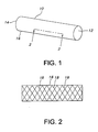
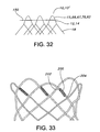
- FIG. 1 depicts stent 10 of the present invention.
- Stent 10 is a hollow tubular structure having opposed open ends 12, 14 and having a tubular wall 16 therebetween.
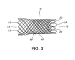
- a portion of the tubular wall 16 is depicted in FIG. 2 as having a plurality of elongate wires 18 formed into the tubular wall 16.
- the elongate wires 18 traverse the length of the stent 10 in a direction traverse to the longitudinal length of the stent 10.
- the elongate wires 18 may be formed into the tubular wall 16 by braiding the wires 18, winding the wires 18, knitting the wires 18, and combinations thereof.
- the wires 18 are braided to form the tubular wall 16.
- braiding and its variants refer to the diagonal intersection of elongate filaments, such as elongate wires, so that each filament passes alternately over and under one or more of the other filaments, which is commonly referred to as an intersection repeat pattern.
- Useful braiding patterns include, but are not limited to, a diamond braid having a 1/1 intersection repeat pattern, a regular braid having a 2/2 intersection repeat pattern or a hercules braid having a 3/3 intersection repeat pattern. The passing of the filaments under and over one and the other results in slidable filament crossings that are not interlooped or otherwise mechanically engaged or constrained.
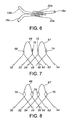
- FIG. 3 A joined or welded stent 10' according to the present invention is depicted in FIG. 3 .
- the elongate wires 18 terminating at open end 12 are mated and adjacently mated wires are secured to one and the other by welds 20 or by other suitable means.
- the wires 18 may be welded together through use of a welding material or the wires 18 may be heatingly and/or meltably fused together without the use of a welding material.
- the wires 18 may mechanically joined, such as, but not limited to, through the use of small-sized or micro-fabricated clamp, crimpable tube, hypotube, and the like.
- the joining of three adjacently mated wires 18 and the welding thereat is depicted in further detailed in FIGS. 4-6 .
- the positioning of adjacently mated wires to form closed-loop end designs is further described in U.S. Application No. 60/472,929, filed May 23, 2003 , which was filed May 24, 2004 as U.S. Application No. 10/852,495 and published as U.S. Patent Application Publication No. 2005/0049682 A1 .
- the stent 10' depicted in FIG. 3 includes 24 wires or filaments 18 of biocompatible material.
- the wires are relatively thin at a diameter of about 0.028 mm (0.011 inches).
- the number of wires and the diameters of the wires, which may be the same or different, depicted in FIG. 3 are not limiting, and other numbers of wires and other wire diameters may suitably be used. Desirably, an even number of wires are used, for example from about 10 to about 36 wires.
- the stent 10' depicted in FIG. 3 has atraumatic open ends 12, 14.
- atraumatic end refers to a terminal end of a stent which is free of sharp wire ends or other sharp projections or deformities which may cause trauma when implanted into a bodily lumen.
- open end 14 of the stent 10' is atraumatic because the stent 10' is braided such that no ends of the wires 18 end at this end of the stent 10'.
- stent 10' may be braided such that all the ends of the wires 18 are distal from the end 14, for example, by commencing the braiding of the stent 10' with wires 18 that are bent in a smooth configuration so that the loop ends 15 of the end 14 have no sharp or traumatically pointed bends or projections.
- the end 12 of the stent 10' is atruamatic because, among other things, even though the wires 18 terminate proximal to the end 14 of the stent 10', certain wires 18 are extended and looped back to provide an atruamatic end with, for example, no sharp or traumatically pointed bends, no sharp wire ends, no other traumatically sharp projections or deformities and the like.
- Adjacently welded wires according to the present invention are depicted further detail in FIGS. 4-6 .
- the terminated wire ends 19a, 19b and 19c are smoothed to remove sharp edges from the ends.
- terminal wire ends 19b and 19c are diagonally cut to remove shape edges as compared to wires that are not diagonally cut (not shown).
- terminal wire end 19a is smoothed to a have a curved portion or a portion having a radius of curvature. Such smoothing may be achieved by use of a laser beam over the terminal end 19a. Heat generated by the laser beam melts the wire material forming a smooth, curved shape.
- terminal ends 19a, 19b and 19c may be, individually or in combination, diagonally cut and/or partially melted to provide a smooth terminal wire end.
- the terminal wire ends 19a, 19b and 19c may be chemically or electro-chemically treated to remove sharp ends. Details of chemically or electro-chemically removing processes are described in U.S. Patent Application No. 10/845,844, filed May 14, 2004 published as US2005/256563 .
- a securably joined region or weld 20a joins wires 18a and 18b
- a securably joined region or weld 20b joins wires 18b and 18c.
- Securably joined regions or welds 20a and 20b are depicted as substantially overlapping one and the other. The present invention, however, is not so limited.
- a securably joined region or weld 20a is longitudinally offset from a securably joined region or weld 20b. Desirably, the length of the securably joined regions or welds 20a and 20b are substantially similar.
- a portion of a securably joined region or weld 20a overlaps a portion of a securably joined region or weld 20b.
- Such offsetting and/or overlapping of the securably joined regions or welds provide greater fatigue life.
- the offset and overlapping welds 20a and 20b of FIG. 6 surpassed 500,000 cycles of stent contraction and/or expansion without fatigue failure. Similar welds that are not offset and overlapping do not pass such fatigue testing.
- Useful welding methods include, but are not limited to, laser welding, electron beam welding, resistance welding, tungsten inert gas welding, metal inert gas welding and combinations thereof.
- laser and electron beam welding the wires are partially melted by the energy provided by the laser or electron beam.
- gas tungsten arc welding GTAW or TIG welding
- MIG metal inert gas
- an arc is generated between a filler electrode and the metal being welded with metal melted from the filler electrode being added to the metal being welded.
- Resistance welding uses the application of electric current and sometimes mechanical pressure to create a weld between two pieces of metal. The weld areas may be shielded with an inert gas.
- Suitable, but non-limiting, inert gasses include argon and argon/gas admixtures, such as argon/hydrogen or argon/helium.
- the wires or filaments 18 are made from a biocompatible material or biocompatible materials.
- Useful biocompatible materials include biocompatible metals, biocompatible alloys and biocompatible polymeric materials, including synthetic biocompatible polymeric materials and bioabsorbable or biodegradable polymeric materials.
- the wires 18 are biocompatible metals or alloys made from, but not limited to, nitinol, stainless steel, cobalt-based alloy such as Elgiloy, platinum, gold, titanium, tantalum, niobium, polymeric materials and combinations thereof.
- Useful synthetic biocompatible polymeric materials include, but are not limited to, polyesters, including polyethylene terephthalate (PET) polyesters, polypropylenes, polyethylenes, polyurethanes, polyolefins, polyvinyls, polymethylacetates, polyamides, naphthalane dicarboxylene derivatives, silks and polytetrafluoroethylenes.
- PET polyethylene terephthalate
- the polymeric materials may further include a metallic, a glass, ceramic or carbon constituent or fiber.
- bioabsorbable or biodegradable polymeric materials include poly(L-lactide) (PLLA), poly(D,L-lactide) (PLA), poly(glycolide) (PGA), poly(L-lactide-co-D,L-lactide) (PLLA/PLA), poly(L-lactide-co-glycolide) (PLLA/PGA), poly(D,L-lactide-co-glycolide) (PLA/PGA), poly(glycolide-co-trimethylene carbonate) (PGA/PTMC), polydioxanone (PDS), Polycaprolactone (PCL), polyhydroxybutyrate (PHBT), poly(phosphazene) poly(D,L-lactide-co-caprolactone) PLA/PCL), poly(glycolide-co-caprolactone) (PGA/PCL), poly(phosphate ester) and the like.
- Wires made from polymeric materials may also include radiopaque materials, such as metallic-based powders or ceramic-based powders, particulates or pastes which may be incorporated into the polymeric material.
- the radiopaque material may be blended with the polymer composition from which the polymeric wire is formed, and subsequently fashioned into the stent as described herein.
- the radiopaque material may be applied to the surface of the metal or polymer stent.
- various radiopaque materials and their salts and derivatives may be used including, without limitation, bismuth, barium and its salts such as barium sulfate, tantalum, tungsten, gold, platinum and titanium, to name a few.
- the stent may be selectively made radiopaque at desired areas along the wire or made be fully radiopaque, depending on the desired end-product and application.
- the wires 18 have an inner core of tantalum, gold, platinum, iridium or combination of thereof and an outer member or layer of nitinol to provide a composite wire for improved radiocapicity or visibility.
- the inner core is platinum and the outer layer is nitinol. More desirably, the inner core of platinum represents about at least 10% of the wire based on the overall cross-sectional percentage.
- nitinol that has not been treated for shape memory such as by heating, shaping and cooling the nitinol at its martensitic and austenitic phases, is also useful as the outer layer. Further details of such composite wires may be found in U.S. Patent Application Publication 2002/0035396 A1 .
- the wires 18 are made from nitinol, or a composite wire having a central core of platinum and an outer layer of nitinol.
- the filling weld material if required by welding processes such as MIG, may also be made from nitinol, stainless steel, cobalt-based alloy such as Elgiloy, platinum, gold, titanium, tantalum, niobium, and combinations thereof, preferably nitinol.
- the material of the cathode is no critical and can be made out of any suitable metal.
- the filling weld material, when present, and the wire 18 may be made of the same material, for example nitinol.
- the filling weld material, when present, may also be fully or partially radiopaque through use of the below-described materials.
- stent 10' is a braided stent having atraumatic ends 12, 14.
- the stent includes filaments or wires 18 that are fully or partially composite filaments or wires 18 to enhance visibility of the wires to provide improved external imaging of the wires in the body.
- the enhanced visibility is enhanced radiopacity to provide improved fluoroscopic or x-ray visualization of said wires in the body.
- Enhanced radiopacity may be achieved by using the above-described radiopaque materials in combination with a biocompatible stent material. Such radiopaque materials are believed to be more visible under fluoroscopic or x-ray visualization due to their higher density than the corresponding biocompatible stent material.
- the present invention is not limited to a stent with improved fluoroscopic or x-ray visualization.
- the stent 10' may also have improved external imaging under magnetic resonance imaging (MRI) and/or ultrasonic visualization techniques. Magnetic resonance imaging is produced by complex interactions of magnetic and radio frequency fields.
- MRI magnetic resonance imaging
- ultrasonic visualization techniques Magnetic resonance imaging is produced by complex interactions of magnetic and radio frequency fields.
- Materials for enhancing MRI visibility include, but not be limited to, metal particles of gadolinium, iron, cobalt, nickel, dysprosium, dysprosium oxide, platinum, palladium, cobalt based alloys, iron based alloys, stainless steels, or other paramagnetic or ferromagnetic metals, gadolinium salts, gadolinium complexes, gadopentetate dimeglumine, compounds of copper, nickel, manganese, chromium, dysprosium and gadolinium.
- the stent 10' of the present invention may include ultrasound resonant material, such as but not limited to gold.
- the stent wires 18 at the open end 14 are bent to form closed loop ends 15 thereat.
- the loop ends 15 are substantially angular having approximately or about a 90° bend.
- the radius of curvature at the point of the bend is desirably minimized.
- the loop end 15 desirably has an angularly bent portion between substantially straight wire portions that do not otherwise have a portion with a significant radius of curvature.
- the loop ends 15, however, are not limited to angular bends of 90° and other bend angles may suitably be used.
- angular bends with a bend angle from about 30° to about 150° are also useful.
- Other useful bend angles include from about 60° to about 120°, from about 70° to about 110°, from about 80° to about 100°, from about 85° to about 95°, and the like.
- loop ends 15 are not limited to substantially angular bend-containing loops and other shaped loop ends, such as semi-circular, semi-elliptical and other smoothly curved or substantially smoothly curved loops, including but not limited to cathedral-shaped loops, may suitably be used.
- a stent is provided with opposed atraumatic, closed-looped ends.
- One of the atraumatic ends may include closed loops having substantially angular bends, as described above, and the other opposed atraumatic end may include a cathedral type arch or loop, as described below.
- certain stent wires 56, 62 may be extended beyond adjacent wires 50, 64, and then looped back to proximal wires 52, 60 and 58, 64, respectively.
- Adjacent portions of wires 50 and 56 are abuttingly disposed at juxtaposed region 68.
- adjacent portions of wires 52 and 60 and the adjacent portion of the extended loop portion 66 are juxtaposingly disposed at abutting region 70; adjacent portions of wires 54 and 62 are juxtaposingly disposed at juxtaposed region 72; and adjacent portions of wires 58 and 64 and the adjacent portion of the extended loop portion 67 are juxtaposingly disposed at juxtaposed region 74.
- the juxtaposingly disposed wire portions in the juxtaposed regions are substantially parallel to one and the other, for example, but not limited to, being within about plus or minus 10 degrees of parallelism to one and the other, preferably, but not limited to within about plus or minus 5 degrees of parallelism.
- the term "juxtaposed” and its variants refer to wires that are proximal to one and the other, desirably in touching relationship.
- the wires may be in a side-to-side relationship, an end-to-end relationship, a crossing over relationship, a butting relationship, and the like.
- welds 76 are offset and overlapping pair of welds as described above.
- the present invention is not limited to the welding of the longitudinally disposed wire portions as depicted in FIGS. 7-8 .
- a weld joint 200 may securably join juxtaposed wires 202 and 204 which form an in integral part of the braid.
- the weld joint 200 is positioned inside the adjacent loop, i.e., after adjacent wires cross, to provide higher radial strength and to withstand higher radial compression forces.
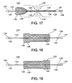
- the extended loop portions 66, 67 are of an arch with equilateral sides' design, which can be referred to as a cathedral type of arch or loop.
- the equilaterally arched loop 78 has an apex or vertex 80.
- vertex and its variants refer to the intersection of two geometric lines or curves.
- apex and its variants refer to a vertex at the top or summit of a loop.
- the equilaterally arched loop 78 does not have any bends, which are defined as areas having dissimilar curvatures on either side of a point, except for the apex 80.
- the equilaterally arched loop 78 has an apex, but not other sharp bends.
- the equilaterally arched loop 78 has one vertex (or apex 80 ) having similar curvatures on either side of the one vertex (or apex 80 ), but does not contain a second vertex having dissimilar curvatures on either side of the second vertex.
- the equilaterally arched loop design offers several advantages, including reduced deployment force, as compared to loop designs having a plurality of vertices or sharp bends.
- a stent When a stent is constrained on or in a delivery system (not shown), the multiple sharp bends in the end loops of the stent typically impinge on the wall of the delivery system and become slightly imbedded thereat, thereby distorting the outer sheath of the delivery system. This results in significantly greater deployment force values.
- the equilaterally arched loop has only one sharp bend, i.e., its apex, and is defined otherwise by a gradual curvature, the gradual curvature portions do not become imbedded in the wall of the delivery system, thereby significantly reducing the resultant deployment force.
- an equilaterally arched loop 82 may have an apex 84 and vertices 86 having substantially straight line portions 88.
- the vertices 86 and the straight line portions 88 have low profile welds 90 there over to adjoin other adjacently abutting stent wires (not shown).
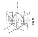
- the equilaterally arched loops 66, 67, 78, 82 of the present invention may be suitably formed by winding their stent wires about shaped pins 98 on a mandrel 100 as depicted in FIG. 13 . Further details of the cathedral type of arch or closed-loop configuration may be found in U.S. Application No. 10/845,844, filed May 15, 2004 published as US2005/256563 .
- either or both of the ends 12, 14 of the stent 10, 10' may have a suture or sutures attached thereto.
- Such sutures which may be textile, polymeric or metallic, are useful for positioning, repositioning, and/or removing the stent 10, 10'.
- Useful polymeric materials include polyester, such as braided polytetrafluoroethylene-impregnated polyesters.
- a suture loop 150 may be disposed at the either or both ends 12, 14 of the stent 10, 10'. Desirably, the suture loop 150 is disposed at the end 12. As depicted in FIG.
- the suture loop 150 is looped among the loop portions, such as portions 66, 67, 78 or 82, of the stent 10, 10'.
- the suture loop 150 may be used by a practitioner for re-positioning and/or removing the stent 10, 10'.
- the suture loop 150 may be grabbed by suitable forceps, such as rat-tooth forceps (not shown). Upon grabbing the suture loop 150 and applying a pulling force thereto, the suture loop 150 cinches and contracts the end 12 or 14 of the stent 10,10', thereby easing movement of the stent 10,10' in vivo.
- the suture loop may be relatively taut over the stent end or may be loosely disposed thereat so as to have some slack.
- the suture loop 150 is a closed-loop device where the ends of the thread or strand forming the suture loop are securably joined together by, for example, tying, gluing and/or fusing the end together. Ultrasonic fusing of polymeric suture thread, in particular knots formed in the thread, is also useful with the present invention. Further details of suitable fused suture knots may be found in U.S. Patent Application No. 11/073,779, filed March 7,2005 published as US2005/209639 .
- a retrieval and/or repositioning loop may be integrally formed into the braided stent structure.
- Such an integral retrieval and/or repositioning loop includes at least of two wires formed into the repositioning and/or retrieval loop which has an elongated portion circumferentially disposed at the end of the stent.
- the reposition and/or retrieval loop includes two sections which run adjacent to each other prior to crossing to permit grabbing of both sections simultaneously by a practitioner. Further details of such a reposition and/or retrieval loop may be found in US2006/276 887 .
- the repositioning and/or retrieval of the stent 10, 10' may also be accomplished without the use of the above-described suture loop 150 and/or the integral loop.
- a repositioning and/or retrieval device such as a catheter, endoscope or the like, may incorporate grabbing detents which may directly engage the loops 66, 67, 78, 82 of the stent 10,10'.
- Such a repositioning and/or retrieval device may also be able to radially compress the stent 10,10' at the loop ends 66, 67, 78, 82 to facilitate repositioning and/or retrieval of a deployed stent, for example by withdrawing the stent 10, 10' into a lumen of the repositioning and/or retrieval device.
- a stent restraining device such as a polymeric sleeve, may be positioned within the lumen of the repositioning and/or retrieval device to secure the stent therein during repositioning and/or retrieval.
- the lumen need not be a substantially cylindrical lumen, and it may have a conical portion, for example in the shape of a funnel, which may be useful for transitioning the stent 10,10' from it deployed diameter to a smaller diameter for securement within the lumen of the repositioning and/or retrieval device.
- one end of the stent may have weld joints which, due to their positioning, provide higher radial strength, i.e., the resultant stents can withstand higher radial compressive forces without fear of weld failure.
- the weld joint 20a, 20b may be positioned between the crossings of adjacent wires 18a,18b,18c, as shown in FIGS. 4-6 .
- the loop ends at the open end 14 of the stent 10 may be longitudinally staggered or offset from one and the other.
- each loop 15 is staggered in alternative long and short longitudinally extending loops.
- Such a staggering or offsetting of the loop ends 15 reduces deployment forces for delivery of the stent.
- longitudinally staggering or offsetting the length and the alignment of the loop ends 15 the force required to deliver the stent 10 to an intended bodily site is reduced as compared to a stent not having a staggered loop end.
- each loop When a stent is tightly constrained in a delivery system, each loop extends to exert a force on a wall of the delivery system, possibly embedding itself into the wall to some extent.
- the loops When the loops are longitudinally staggered, the force exerted by each loop is laterally distributed in a more even fashion. Such staggering reduces the force required to move the stent from the wall of the delivery system, thereby reducing the overall deployment force.
- staggered loops are less likely to interfere with each other as compared to non-staggered loops, again reducing the deployment force. In other words, staggered loops will less likely impede the delivery of the stent as compared to non-staggered loops.
- FIG. 12 which is a partial exploded view of a portion of the stent end 14 of FIG. 3
- stent loops 15a are staggered from stent loops 15b.
- the staggering of the loops results in a longitudinal offset, d, between the apexes or apices of the adjacent loops.
- one set of loops 15a are offset from another set of loops 15b by a single longitudinal offset, d.
- the stent end 14 may have staggered loop ends having more than one or a plurality of longitudinal offsets.
- the staggered loop ends 15a, 15b with either a single offset or a plurality of offsets may suitably be formed by providing a mandrel with longitudinally offset pins (not shown) and commencing braiding or otherwise positioning the stent wires thereat.
- the stent 10 may be fully, substantially or partially covered with a polymeric material 102.
- the covering may be in the form of a tubular structure.
- a polymeric material is silicone.
- the polymeric material and/or silicone 102 may be disposed on external surfaces 104 of the stent 10, as depicted in FIG. 15 , or disposed on the internal surfaces 106 of the stent 10, as depicted in FIG. 16 , or combinations thereof.
- the silicone covering may be suitably formed by dip coating the stent. Details of such dip coating may be found in U.S. Patent No. 5,875,448 .
- the present invention is not limited to forming the silicone film by dip coating, and other techniques, such as spraying, may suitably be used.
- the silicone may be cured.
- the curing is low temperature curing, for example from about room temperature to about 90°C for a short period of time, for example from about 10 minutes or more to about 16 hours.
- the cured silicone covering may also be sterilized by electronic beam radiation, gamma radiation ethylene oxide treatment and the like. Further details of the curing and/or sterilization techniques may be found in U.S. Patent Application No. 6,099,562 .
- Argon plasma treatment of the cured silicone may also be used. Argon plasma treatment of the cured silicone modifies the surface to the cured silicone to, among other things, make the surface less sticky.
- stent 10,10',128 is usable to maintain patency of a bodily vessel, such as in the coronary or peripheral vasculature, esophagus, trachea, bronchi colon, biliary tract, urinary tract, prostate, brain, and the like.
- the stent 10,10' may be treated with any of the following: anti-thrombogenic agents (such as heparin, heparin derivatives, urokinase, and PPack (dextrophenylalanine proline arginine chloromethylketone); anti-proliferative agents (such as enoxaprin, angiopeptin, or monoclonal antibodies capable of blocking smooth muscle cell proliferation, hirudin, and acetylsalicylic acid); anti-inflammatory agents (such as dexamethasone, prednisolone, corticosterone, budesonide, estrogen, sulfasalazine, and mesalamine); antineoplastic/antiproliferative/anti-miotic agents (such as paclitaxel, 5-fluorouracil, cisplatin, vinblastine, vincristine, epothilones, endostatin, angiostatin and thymidine kinase inhibitors);
- the general tubular shape may be varied.
- the tubular shape may have a varied diameter, an inwardly flared end, an outwardly flared end and the like.
- the ends of the stent may have a larger diameter than the middle regions of the stent.
- a braided stent with outwardly flared ends is further described in U.S. Patent No. 5,876,448 .
- a stent delivery and deployment system is provided.
- a stent delivery and deployment system 120 is provided.
- the system 120 includes a catheter 122 having a distal end 124 and a proximal end 126; a stent 128 having a distal end 130 and a proximal end 132; a retractable sheath 134 having a distal end 136 and a proximal end 138; a marker band 140 disposed at the distal end 136 of the delivery sheath 134; and a post-deployment marker band 142 disposed on an inner member 144 of the catheter 122 toward the proximal end 126 of the catheter 122; interrelated as shown.
- the marker band 140 may be placed at the distal end 136 of the sheath 134.
- Prior deployment sheath 134 substantially covers or even extends beyond the distal end 130 of the stent 128.
- the marker band 140 is disposed to overlap the distal end 130 of the stent 128 in the pre-deployment stage.
- Typical prior art systems have a marker band positioned on the sheath, but beyond the stent, which complicates stent placement. Another reason for such marker placement 140 overlapping the stent 128 is for constraining the stent 128 prior to deployment.
- the stent may expand into the polymeric sheath during sterilization and/or storage. Such expansion induces higher frictional forces at this location, ultimately increasing the deployment force required to deploy the stent.
- deployment forces in the range of about 14 pounds-force is required.
- the system 120 requires significantly less deployment force, approximately in the range of about 22N (5) to about 27N (6 pounds-force). Desirably, deployment forces with the system 120 of the present invention are less than about 10 pounds-force, more desirably less than about 8 pounds-force, preferably less than about 7 pounds-force or less.
- the system 120 comprises a post-deployment marker band 142 disposed on an inner member 144 of the catheter 122 toward the proximal end 126 of the catheter 122.
- the post-deployment marker band 142 is placed proximally or before the stricture or damaged vessel site 146. Such placement ensures that the stent 128 will always completely span the vessel site 146 even when the stent 128 foreshortens as it expands during delivery.
- the stricture or damaged vessel site 146 may suitably include bodily tissue, bodily organs, vascular lumens, non-vascular lumens and combinations thereof, such as, but not limited to, in the coronary or peripheral vasculature, esophagus, trachea, bronchi, colon, biliary tract, urinary tract, prostate, brain, stomach and the like
- the markers 140 and 142 may comprise any useful radiopaque material or materials including any metal or plastics being radiopaque or capable of being impregnated with radiopaque materials.
- Useful radiopaque materials include, but are not limited to gold, barium sulfate, ferritic particles, platinum, platinum-tungsten, palladium, platinum-iridium, rhodium, tantalum or combinations thereof.
- the sheath 134 may comprise any plastic or polymeric material, desirably a somewhat hard but flexible plastic or polymeric material.
- the sheath 134 may be transparent or translucent, desirably substantially or partially transparent.
- the sheath 134 may be constructed of any suitable biocompatible materials, such as, but not limited to, polymers and polymeric materials, including fillers such as metals, carbon fibers, glass fibers or ceramics.
- suitable sheath materials include, but are not limited, polyethylene, polypropylene, polyvinyl chloride, polytetrafluoroethylene, including expanded polytetrafluoroethylene (ePTFE), fluorinated ethylene propylene, fluorinated ethylene propylene, polyvinyl acetate, polystyrene, poly(ethylene terephthalate), naphthalene dicarboxylate derivatives, such as polyethylene naphthalate, polybutylene naphthalate, polytrimethylene naphthalate and trimethylenediol naphthalate, polyurethane, polyurea, silicone rubbers, polyamides, polyimides, polycarbonates, polyaldehydes, polyether ether ketone, natural rubbers, polyester copolymers,
- FIGS. 17 and 20 depict a partially deployed stent 128.
- FIGS. 18 and 21 depict a colonically deployed stent with the enlarged stent portion 130 being distal to the site 146.
- FIGS. 19 and 22 depict a duodenally deployed stent with the enlarged stent portion 132 being proximal to the site 146.
- FIGS. 23-31 depict additional details of the arrangement of the marker 140 with the system 120.
- the marker 140 is disposed between the sheath 134 and the stent 128 at the distal end 136 of the sheath 134 with the marker 140 being placed proximal to the distal end 130 of the stent 128.
- the distal end 136 of the sheath 134 is depicted as covering and extending beyond the distal end 130 of the stent 128, the present invention is not so limited.
- the distal end 136 of the sheath 134 may be flush or substantially flush with the distal end 130 of the stent 128 (not shown).
- the sheath 134, the stent 128 and the marker 140 are continuous tubular or cylindrical members.
- the marker 140 need not be a continuous tubular member, but may be, for example, a segmented member.
- the marker 140 may be disposed over the outside surface or exterior portion of the sheath 134. As depicted in FIGS. 25 and 26 the marker 140 may be adjacently disposed, including substantially disposed, to or over the distal end 130 of the stent 128.
- FIGS. 28-31 depict alternate ways of the placement of the marker 140 with the sheath 134.
- the marker 140 may be fully embedded within the sheath 134.
- the marker 140 may interrupt or partially interrupt the sheath 134.
- the marker may be partially embedded within the sheath 134, but being exposed at the interior or luminal surface of the sheath 134, which is generally depicted as the bottom portion of the sheath 134 in FIG. 30 .
- the marker may be partially embedded within the sheath 134, but being exposed at the exterior surface of the sheath 134, which is generally depicted as the upper portion of the sheath 134 in FIG. 30 .
- an implantable stent in one aspect of the present invention, includes a plurality of elongate wires braided to form a hollow tubular structure having a tubular wall to define an interior surface and an exterior surface and having opposed open first and second ends, wherein the opposed open first and second ends are atraumatic ends, and further wherein the wires include composite wires to enhance visibility of the wires to provide improved external imaging of the wires in the body.
- the enhanced visibility is enhanced radiopacity and the external imaging is fluoroscopic or x-ray visualization.
- the atraumatic ends of the stent are desirably free of any loose wire ends.
- the elongate composite wires of the stent may be metallic wires having an outer metallic portion including a first metal and an inner metallic core portion including a second metal, wherein the first metal is different from the second metal.
- the second metal of the inner core includes a radiopaque material selected from gold, barium sulfate, ferritic particles, platinum, platinum-tungsten, palladium, platinum-iridium, rhodium, tantalum or combinations thereof.
- the first metal of the outer portion may include nitinol.
- the stent of this aspect of the present invention desirably may also have wires that terminate at the second end, wherein the wires at the first end are arranged in a series of closed loops with each loop having an apex defined by a bend in one of the wires and having an opposed base defined by crossing of adjacent wires, and further wherein the apex of adjacent closed loops are longitudinally offset from one and the other.
- the stent of this aspect of the present invention desirably may also have wires that terminate at the second open end, and adjacently juxtaposed wires are securably joined at the second open end to provide first securably joined regions, wherein at least one of the adjacently juxtaposed stent wires are extended past the first securably joined regions and further wherein the extended and looped wire is securably joined to the proximal pair of wires with second securably joined regions to define closed loop wire ends.
- the wires are securably joined by welding the wired and further wherein the securably joined regions are welds.
- the stent of this aspect of the present invention desirably may also have wires that terminate at the second open end, and further wherein adjacently juxtaposed wires at the second open end are securably joined to provide securably joined regions, wherein ends of the terminated wires are smoothed to remove sharp edges from the wire ends.
- the wires are securably joined by welding the wired and further wherein the securably joined regions are welds.
- the stent of this aspect of the present invention desirably may also have wires that terminate at the second open end, and adjacently juxtaposed wires are securably joined at the second open end to provide first securably joined regions, wherein at least one of the adjacently juxtaposed stent wires are extended past the first securably joined regions and looped such that the extended end abuts a proximal pair of stent wires; and further wherein the extended and looped wire is securably joined to the proximal pair of wires with second securably joined regions which are longitudinally offset from the first securably joined regions.
- the wires are securably joined by welding the wired and further wherein the securably joined regions are welds.
- the first and the second welds may have a substantially same longitudinally extending extend.
- the first and the second welds may have longitudinally extending portions which overlap one and the other.
- the stent of this aspect of the present invention may also be partially or fully coated with a polymeric material.
- the stent may further include hollow tubular graft disposed partially or fully over the interior or the exterior surface.
- the graft is a polymeric material.
- the polymeric material may be selected from polyester, polypropylene, polyethylene, polyurethane, polynaphthalene, polytetrafluoroethylene, expanded polytetrafluoroethylene, silicone, and combinations thereof.
- a method for making an implantable stent includes the steps of (i) providing a plurality of elongate wires, wherein the elongate wires include composite wires to enhance visibility of the wires to provide improved external imaging of the wires in the body; and (ii) braiding the wires to form a hollow tubular structure having a tubular wall to define an interior surface and an exterior surface and having opposed open first and second ends, wherein the opposed open first and second ends are atraumatic ends.
- the enhanced visibility is enhanced radiopacity and the external imaging is fluoroscopic or x-ray visualization.
- this aspect of the present invention may further include the step of arranging the wires at the first end in a series of closed loops with each loop having an apex defined by a bend in one of the wires and having an opposed base defined by crossing of adjacent wires, wherein the apex of adjacent closed loops are longitudinally offset from one and the other.
- the method this aspect of the present invention may also further include the steps of terminating the wires at the second end; aligning the wires at the second end into a plurality of mated adjacent wires to define a plurality of juxtaposed regions; and securably joining the mated adjacent wires to one and the other at the juxtaposed regions to define a closed loop at the second end.
- the step of securably joining the wires includes welding the wires.
- the method this aspect of the present invention may further include the steps of terminating the wires at the second end to form terminated wire ends; aligning the wires at the second end into a plurality of mated adjacent wires to define a plurality of juxtaposed regions; securably joining the mated adjacent wires to one and the other at the juxtaposed regions to define a plurality of securably joined regions; and smoothing the terminated wire ends by removing sharp edges from the wire ends.
- the step of securably joining the wires includes welding the wires, and further wherein the securably joined regions are welds.
- the method this aspect of the present invention may further include the steps of terminating the wires at the second end; aligning the wires at the second end into a plurality of mated adjacent wires to define a plurality of juxtaposed regions; extending at least one of the mated stent wires to provide an extended stent wire; looping the extended stent wire so the extended end abuts a proximal pair of stent wires; securably joining the mated adjacent wires to one and the other at the juxtaposed regions; and securably joining the extended and looped wire to the proximal pair of wires with a pair of longitudinally offset securably joined regions.
- the step of securably joining the wires includes welding the wires, and further wherein the securably joined regions are welds.
- a stent delivery and deployment system in another aspect not part of the present invention, includes a delivery catheter having a distal end; an elongate radially self-expanding stent having a distal end adjacent the distal end of the catheter; an elongate sheath retractably positioned about the stent so as to maintain the stent in a radially compressed delivery condition about the distal end of the catheter; and a retaining band positioned adjacent the distal end of the stent, the retaining band being retractable with the sheath so as to allow longitudinally progressive and radial expansion of the stent upon the retraction of the sheath for deploying the stent.
- the retaining band may include a radiopaque marker.
- the band may also be formed of a radiopaque material.
- a method of delivering and deploying an expandable stent includes the steps of disposing a radially expanding stent at a distal end of a delivery catheter; positioning a retractable sheath having a retaining band adjacent a distal end of the stent over the stent so as to maintain the stent in a radially compressed delivery condition; and retracting the sheath and the retaining band with respect to the distal end of the catheter to allow longitudinal progressive expansion of the stent.
- the sheath and the band are retracted together.
- the retaining band may include a radiopaque marker or is formed of a radiopaque material.
- the positioning step may further include the step of positioning the band at the distal end of the stent.
- the stent is a braided stent having opposed first and second atraumatic open ends.
- a method for making an implantable stent includes the steps of (i) providing a plurality of elongate stent wires; (ii) forming the wires into a hollow tubular structure having opposed first and second open ends; (iii) terminating the wires at the second end to form terminated wire ends; (iii) aligning the wires at the second end into a plurality of mated adjacent wires to define a plurality of juxtaposed regions; (iv) welding the mated adjacent wires to one and the other at the juxtaposed regions to define a plurality of welds; and (v) smoothing the terminated wire ends by removing sharp edges from the wire ends.
- the step of smoothing the terminated wire ends may further include removing a portion of wire material at the terminated wire end to provide a diagonally extending portion at the wire end; removing a portion of wire material at the terminated wire end to provide a curved portion at the wire end; heating the terminated wire end to partially melt wire material at the wire end; and combinations thereof.
- the step of heating includes passing a laser beam over the terminated wire end.
- the method of this aspect of the present invention may further include the steps of chemically or electro-chemically removing a portion of the welds; chemically or electro-chemically removing a portion of the terminated wire ends and combinations thereof.
- the method of this aspect of the present invention of claim 22 may include forming the tubular structure by braiding the wires, winding the wires, knitting the wires, and combinations thereof.
- the method of this aspect of the present invention claim 22 may include a wire including a radiopaque material.
- the elongate wires may include biocompatible materials selected from the group consisting of nitinol, cobalt-based alloy, stainless steel, platinum, gold, titanium, tantalum, niobium, polymeric materials and combinations thereof, desirably, nitinol.
- the elongate wires may be composite wires for improved radiopacity, such as wires having an inner core radiopaque material selected from the group consisting of gold, barium sulfate, ferritic particles, platinum, platinum-tungsten, palladium, platinum-iridium, rhodium, tantalum or combinations thereof and an outer portion of nitinol.
- an implantable stent in another aspect of the present invention, includes a plurality of wires arranged to form a hollow tubular structure having a tubular wall to define an interior surface and an exterior surface and having opposed open first and second ends, wherein the wires terminate at the second open end and adjacently juxtaposed wires are welded at the second open end with a welding material to provide welds, and further wherein ends of the terminated wires are smoothed to remove sharp edges from the wire ends and to provide a longitudinally extending wire portion at the wire ends.
- the longitudinally extending wire portion at the wire ends may include a diagonally extending portion at the wire end, may include a curved portion at the wire end, may include partially melt wire material at the wire end, and combinations thereof.
- the stent of this aspect of the present invention may include wires including a biocompatible material selected from the group consisting of nitinol, stainless steel, cobalt-based alloy, platinum, gold, titanium, tantalum, niobium, polymeric materials and combinations thereof and an outer portion of nitinol.
- the weld material and the wire material may be nitinol.
- the elongate wires have an inner core radiopaque material selected from the group consisting of gold, barium sulfate, ferritic particles, platinum, platinum-tungsten, palladium, platinum-iridium, rhodium, tantalum or combinations thereof and an outer portion of nitinol.
- the stent of this aspect of the present invention may include a coated or partially coated stent wherein the stent is coated with a polymeric material.
- the stent may be is partially or fully covered with a biologically active material which is elutably disposed with the polymeric material.
- the stent of this aspect of the present invention may further include a hollow tubular graft disposed over the interior or the exterior surface.
- the graft may be a polymeric material, such as polyester, polypropylene, polyethylene, polyurethane, polynaphthalene, polytetrafluoroethylene , expanded polytetrafluoroethylene, silicone, and combinations thereof.
- the stent of this aspect of the present invention is a braided stent.
- a method for making an implantable stent including (i) providing a plurality of elongate stent wires; forming the wires into a hollow tubular structure having opposed first and second open ends; terminating the wires at the second end; aligning the wires at the second end into a plurality of mated adjacent wires to define a plurality of juxtaposed regions; and extending at least one of the mated stent wires to provide an extended stent wire; looping the extended stent wire so the extended end abuts a proximal pair of stent wires; welding the mated adjacent wires to one and the other at the juxtaposed regions; and welding the extended and looped wire to the proximal pair of wires with a pair of longitudinally offset welds.
- the pair of longitudinally offset welds may have a substantially same longitudinally extending extend, may have a portion which overlap one and the other, or combinations thereof.
- the step of forming the tubular structure may include braiding the wires, winding the wires, knitting the wires, and combinations thereof.
- the wire may include a radiopaque material.
- the elongate wires may include biocompatible materials selected from the group consisting of nitinol, cobalt-based alloy, stainless steel, platinum, gold, titanium, tantalum, niobium, polymeric materials and combinations thereof, desirably nitinol.
- the elongate wires may be composite wires for improved radiopacity.
- the elongate wires may have an inner core radiopaque material selected from the group consisting of gold, barium sulfate, ferritic particles, platinum, platinum-tungsten, palladium, platinum-iridium, rhodium, tantalum or combinations and an outer portion of nitinol.
- the step of welding may include welding selected from the group consisting of laser welding, electron beam welding resistance welding, tungsten inert gas welding, metal inert gas welding and combinations thereof.
- an implantable stent in another aspect of the present invention, includes a plurality of wires arranged to form a hollow tubular structure having a tubular wall to define an interior surface and an exterior surface and having opposed open first and second ends, wherein the wires terminate at the second open end and adjacently juxtaposed wires are welded at the second open end with a welding material to provide first welds, wherein at least one of the adjacently juxtaposed stent wires are extended past the welds and looped such that the extended end abuts a proximal pair of stent wires; and further wherein the extended and looped wire is welded with a welding material to the proximal pair of wires with second welds which are longitudinally offset from the first welds.
- the first and the second welds may have a substantially same longitudinally extending extend, may have a longitudinally extending portions which overlap one and the other, or combinations thereof.
- the wires may include a biocompatible material selected from the group consisting of nitinol, stainless steel, cobalt-based alloy, platinum, gold, titanium, tantalum, niobium, polymeric materials and combinations thereof.
- the weld material and the wire material may be nitinol.
- the elongate wires may have an inner core radiopaque material selected from the group consisting of gold, barium sulfate, ferritic particles, platinum, platinum-tungsten, palladium, platinum-iridium, rhodium, tantalum or combinations thereof and an outer portion of nitinol.
- the stent may be coated with a polymeric material.
- the stent may be partially or fully covered with a biologically active material which is elutably disposed with the polymeric material.
- the stent may further include a hollow tubular graft disposed over the interior or the exterior surface.
- the graft may be a polymeric material, such as a polymeric material is selected from the group consisting of polyester, polypropylene, polyethylene, polyurethane, polynaphthalene, polytetrafluoroethylene, expanded polytetrafluoroethylene, silicone, and combinations thereof.
- the stent is a braided stent.
- an implantable stent in another aspect of the present invention, includes a plurality of wires arranged to form a hollow tubular structure having a tubular wall to define an interior surface and an exterior surface and having opposed open first and second ends, wherein the wires at the first end are arranged in a series of closed loops with each loop having an apex defined by a bend in one of the wires and having an opposed base defined by crossing of adjacent wires, wherein the apex of adjacent closed loops are longitudinally offset from one and the other.
- the closed loops may define geometric areas of substantially the same size, may have substantially similar geometric shapes and combinations thereof.
- the adjacent bases of the closed loops may be longitudinally offset from one and the other, may not be substantially longitudinally offset from one and the other, and combinations thereof.
- the loops may have a geometric pattern in a general diamond shape having four corners with the apex forming a top corner, the base forming an opposed bottom corner and opposed side corners defined by crossing of adjacent wires which are different wires from those defining the base corner.
- the opposed side corners of adjacent closed loops may be longitudinally offset from one and the other, may not be substantially longitudinally offset from one and the other or combinations thereof.
- Each of the apexes of the closed loops may be longitudinally positioned beyond the opposed corner of any of the closed loops.
- Each of the apexes may have an area of curvature and adjacent apexes are longitudinally offset by a longitudinal distance where the adjacent apexes of the closed loops are longitudinally positioned within the area of curvature of adjacent loops.
- the wires may terminate at the second open end and adjacently juxtaposed wires are welded at the second open end with a welding material to provide first welds, wherein at least one of the adjacently juxtaposed stent wires are extended past the welds and further wherein the extended and looped wire is welded with a welding material to the proximal pair of wires with second welds to define closed loop wire ends.
- the closed loop wire ends at the second open end may have apexes where the apexes of adjacent closed loop wire ends are longitudinally offset from one and the other.
- the second welds may be longitudinally offset from the first welds.
- the ends of the terminated wires may be smoothed by removing sharp edges from the wire ends.
- the wires may include a biocompatible material selected from the group consisting of nitinol, stainless steel, cobalt-based alloy, platinum; gold, titanium, tantalum, niobium, polymeric materials and combinations thereof and an outer portion of nitinol.
- the s weld material and the wire material may be nitinol.
- the elongate wires may have an inner core radiopaque material selected from the group consisting of gold, barium sulfate, ferritic particles, platinum, platinum-tungsten, palladium, platinum-iridium, rhodium, tantalum or combinations thereof and an outer portion of nitinol.
- the stent may be coated with a polymeric material.
- the stent may be partially or fully covered with a biologically active material which is elutably disposed with the polymeric material.
- a hollow tubular graft may be disposed over the interior or the exterior surface.
- the graft may be a polymeric material, such as a polymeric material is selected from the group consisting of polyester, polypropylene, polyethylene, polyurethane, polynaphthalene, polytetrafluoroethylene, expanded polytetrafluoroethylene, silicone, and combinations thereof.
- the stent may be a braided stent.
- a method for making an implantable stent includes (i) providing a plurality of elongate stent wires; and (ii) forming the wires into a hollow tubular structure having opposed first and second open ends, wherein the wires at the first end are arranged in a series of closed loops with each loop having an apex defined by a bend in one of the wires and having an opposed base defined by crossing of adjacent wires, wherein the apex of adjacent closed loops are longitudinally offset from one and the other.
- the method may further include the steps of (i) terminating the wires at the second end; (ii) aligning the wires at the second end into a plurality of mated adjacent wires to define a plurality of juxtaposed regions; and (iii) welding the mated adjacent wires to one and the other at the juxtaposed regions to define a closed loop at the second end.
- the adjacent closed loops at the second end may be longitudinally staggered from one and the other.
- the step of forming the tubular structure may include braiding the wires, winding the wires, knitting the wires, and combinations thereof.
- the wire may include a radiopaque material.
- the elongate wires may include biocompatible materials selected from the group consisting ofnitinol, cobalt-based alloy, stainless steel, platinum, gold, titanium, tantalum, niobium, polymeric materials and combinations thereof. Desirably, the elongate wires may include nitinol.
- the elongate wires may be composite wires for improved radiopacity.
- the elongate wires may have an inner core radiopaque material selected from the group consisting of gold, barium sulfate, ferritic particles, platinum, platinum-tungsten, palladium, platinum-iridium, rhodium, tantalum or combinations thereof and an outer portion of nitinol.
- a stent delivery and deployment system includes (i) a delivery catheter having a distal end; (ii) an elongate radially self-expanding stent having a distal end adjacent the distal end of the catheter; (iii) an elongate sheath retractably positioned about the stent so as to maintain the stent in a radially compressed delivery condition about the distal end of the catheter; and (iv) a retaining band positioned adjacent the distal end of the stent, the retaining band being retractable with the sheath so as to allow longitudinally progressive and radial expansion of the stent upon the retraction of the sheath for deploying the stent.
- the retaining band may be positioned at the distal end of the stent, may be positioned between the stent and the sheath, may be positioned external to the sheath and combinations thereof.
- the retaining band may include a radiopaque marker.
- the band may be imbedded into the sheath.
- the band may be formed of a radiopaque material.
- a method of delivering and deploying an expandable stent includes the steps of (i) disposing a radially expanding stent at a distal end of a delivery catheter; (ii) positioning a retractable sheath having a retaining band adjacent a distal end of the stent over the stent so as to maintain the stent in a radially compressed delivery condition; and (iii) retracting the sheath and the retaining band with respect to the distal end of the catheter to allow longitudinal progressive expansion of the stent.
- the sheath and the band may be retracted together.
- the band may imbedded into the sheath.
- the retaining band may include a radiopaque marker.
- the positioning step may include positioning the band at the distal end of the stent.
- a system for locating a stent for delivery and deployment at an intraluminal site includes (i) a delivery catheter having a distal end; (ii) an elongate deployable stent mounted to the distal end of the catheter; and (iii) a radiopaque marker on the distal end of the catheter; the stent being mounted on the distal end to overlie the marker.
- the stent may be a distensible stent.
- the marker may be positioned adjacent one end of the stent.
- the stent may have a distal end and a proximal end and the marker may positioned adjacent the proximal end.
- a method of deploying a stent at a damaged vessel site includes the step of (i) providing a catheter having a delivery end and a radiopaque marker adjacent there to; (ii) positioning an expandable stent on the delivery end so as to overlie the marker; (iii) placing the marker at a location proximal to the damaged vessel site; and (iv) allowing the stent to expand across the damaged vessel site.
- the marker may be placed before the damaged vessel site to ensure positioning of the expanded stent across the damaged vessel site.
- a stent delivery and deployment system may include (i) a delivery catheter having a distal end; (ii) an elongate radially self-expanding stent having a distal end adjacent the distal end of the catheter, the stent including a plurality of wires arranged to form a hollow tubular structure having a tubular wall to define an interior surface and an exterior surface and having opposed open first and second ends, wherein the wires terminate at the second open end and adjacently juxtaposed wires are welded at the second open end with a welding material to provide welds, and further wherein ends of the terminated wires are smoothed to remove sharp edges from the wire ends and to provide a longitudinally extending wire portion at the wire ends; (iii) an elongate sheath retractably positioned about the stent so as to maintain the stent in a radially compressed delivery condition about the distal end of the catheter; and (iv) a retaining band positioned adjacent the distal end of the stent
- a stent delivery and deployment system may also include (i)a delivery catheter having a distal end; (ii) an elongate radially self-expanding stent having a distal end adjacent the distal end of the catheter, the stent including a plurality of wires arranged to form a hollow tubular structure having a tubular wall to define an interior surface and an exterior surface and having opposed open first and second ends, wherein the wires terminate at the second open end and adjacently juxtaposed wires are welded at the second open end with a welding material to provide first welds, wherein at least one of the adjacently juxtaposed stent wires are extended past the welds and looped such that the extended end abuts a proximal pair of stent wires; and further wherein the extended and looped wire is welded with a welding material to the proximal pair of wires with second welds which are longitudinally offset from the first welds; (iii) an e
- a stent delivery and deployment system may include (i) a delivery catheter having a distal end; (ii) an elongate radially self-expanding stent having a distal end adjacent the distal end of the catheter, the stent including a plurality of wires arranged to form a hollow tubular structure having a tubular wall to define an interior surface and an exterior surface and having opposed open first and second ends, wherein the wires at the first end are arranged in a series of closed loops with each loop having an apex defined by a bend in one of the wires and having an opposed base defined by crossing of adjacent wires, wherein the apex of adjacent closed loops are longitudinally offset from one and the other; (iii) an elongate sheath retractably positioned about the stent so as to maintain the stent in a radially compressed delivery condition about the distal end of the catheter; and (iv) a retaining band positioned adjacent the distal end of the stent, the
Priority Applications (1)
| Application Number | Priority Date | Filing Date | Title |
|---|---|---|---|
| EP11184665.5A EP2407127B1 (en) | 2004-11-10 | 2005-11-10 | Atraumatic stent with reduced deployment force |
Applications Claiming Priority (3)
| Application Number | Priority Date | Filing Date | Title |
|---|---|---|---|
| US62672904P | 2004-11-10 | 2004-11-10 | |
| US68063005P | 2005-05-13 | 2005-05-13 | |
| PCT/US2005/041083 WO2006053270A2 (en) | 2004-11-10 | 2005-11-10 | Atraumatic stent with reduced deployment force, method for making the same and method and apparatus for deploying and positioning the stent |
Related Child Applications (2)
| Application Number | Title | Priority Date | Filing Date |
|---|---|---|---|
| EP11184665.5A Division EP2407127B1 (en) | 2004-11-10 | 2005-11-10 | Atraumatic stent with reduced deployment force |
| EP11184665.5 Division-Into | 2011-10-11 |
Publications (2)
| Publication Number | Publication Date |
|---|---|
| EP1833417A2 EP1833417A2 (en) | 2007-09-19 |
| EP1833417B1 true EP1833417B1 (en) | 2012-02-01 |
Family
ID=35825418
Family Applications (2)
| Application Number | Title | Priority Date | Filing Date |
|---|---|---|---|
| EP11184665.5A Active EP2407127B1 (en) | 2004-11-10 | 2005-11-10 | Atraumatic stent with reduced deployment force |
| EP05825595A Active EP1833417B1 (en) | 2004-11-10 | 2005-11-10 | Atraumatic stent with reduced deployment force and method for making the same |
Family Applications Before (1)
| Application Number | Title | Priority Date | Filing Date |
|---|---|---|---|
| EP11184665.5A Active EP2407127B1 (en) | 2004-11-10 | 2005-11-10 | Atraumatic stent with reduced deployment force |
Country Status (8)
| Country | Link |
|---|---|
| US (3) | US7462192B2 (ja) |
| EP (2) | EP2407127B1 (ja) |
| JP (1) | JP5009163B2 (ja) |
| AT (1) | ATE543469T1 (ja) |
| AU (1) | AU2005304338B2 (ja) |
| CA (1) | CA2585284C (ja) |
| ES (2) | ES2381558T3 (ja) |
| WO (1) | WO2006053270A2 (ja) |
Cited By (2)
| Publication number | Priority date | Publication date | Assignee | Title |
|---|---|---|---|---|
| US10888444B2 (en) | 2017-11-01 | 2021-01-12 | Boston Scientific Scimed, Inc. | Esophageal stent including a valve member |
| US11304795B2 (en) | 2017-10-25 | 2022-04-19 | Boston Scientific Scimed, Inc. | Stent with atraumatic spacer |
Families Citing this family (133)
| Publication number | Priority date | Publication date | Assignee | Title |
|---|---|---|---|---|
| US7018401B1 (en) | 1999-02-01 | 2006-03-28 | Board Of Regents, The University Of Texas System | Woven intravascular devices and methods for making the same and apparatus for delivery of the same |
| US8628564B2 (en) | 2004-05-25 | 2014-01-14 | Covidien Lp | Methods and apparatus for luminal stenting |
| US8617234B2 (en) | 2004-05-25 | 2013-12-31 | Covidien Lp | Flexible vascular occluding device |
| JP2008502378A (ja) | 2004-05-25 | 2008-01-31 | チェストナット メディカル テクノロジーズ インコーポレイテッド | フレキシブルな血管閉鎖デバイス |
| KR101300437B1 (ko) | 2004-05-25 | 2013-08-26 | 코비디엔 엘피 | 동맥류용 혈관 스텐트 |
| US20060206200A1 (en) | 2004-05-25 | 2006-09-14 | Chestnut Medical Technologies, Inc. | Flexible vascular occluding device |
| WO2006053270A2 (en) * | 2004-11-10 | 2006-05-18 | Boston Scientific Limited | Atraumatic stent with reduced deployment force, method for making the same and method and apparatus for deploying and positioning the stent |
| EP3597256B1 (en) | 2005-05-13 | 2023-01-18 | Boston Scientific Medical Device Limited | Integrated stent repositioning and retrieval loop |
| AU2005332044B2 (en) | 2005-05-25 | 2012-01-19 | Covidien Lp | System and method for delivering and deploying and occluding device within a vessel |
| EP1769774A1 (fr) * | 2005-10-03 | 2007-04-04 | Noureddine Frid | Endoprothèse radio-opaque |
| US8152833B2 (en) | 2006-02-22 | 2012-04-10 | Tyco Healthcare Group Lp | Embolic protection systems having radiopaque filter mesh |
| US20070203564A1 (en) * | 2006-02-28 | 2007-08-30 | Boston Scientific Scimed, Inc. | Biodegradable implants having accelerated biodegradation properties in vivo |
| KR100776686B1 (ko) * | 2006-05-11 | 2007-11-28 | 재단법인서울대학교산학협력재단 | 편조 스텐트 및 그 제조방법 |
| US7867283B2 (en) * | 2006-05-30 | 2011-01-11 | Boston Scientific Scimed, Inc. | Anti-obesity diverter structure |
| US9265866B2 (en) * | 2006-08-01 | 2016-02-23 | Abbott Cardiovascular Systems Inc. | Composite polymeric and metallic stent with radiopacity |
| US9173733B1 (en) * | 2006-08-21 | 2015-11-03 | Abbott Cardiovascular Systems Inc. | Tracheobronchial implantable medical device and methods of use |
| EP2059619B1 (en) | 2006-09-06 | 2010-11-17 | Cook Incorporated | Nickel-titanium alloy including a rare earth element |
| US8298564B2 (en) * | 2006-09-27 | 2012-10-30 | Medtronic, Inc. | Two part antimicrobial boot |
| US20080075628A1 (en) * | 2006-09-27 | 2008-03-27 | Medtronic, Inc. | Sterilized minocycline and rifampin-containing medical device |
| US9895242B2 (en) | 2006-10-22 | 2018-02-20 | Idev Technologies, Inc. | Secured strand end devices |
| JP5455633B2 (ja) * | 2006-10-22 | 2014-03-26 | アイデブ テクノロジーズ インコーポレイテッド | ステント前進のためのデバイスおよび方法 |
| AU2015203279B2 (en) * | 2006-10-22 | 2017-06-01 | Idev Technologies, Inc. | Methods for securing strand ends and the resulting devices |
| WO2008112076A1 (en) * | 2007-03-07 | 2008-09-18 | Boston Scientific Scimed, Inc. | Radiopaque polymeric stent |
| DE102007030751B4 (de) * | 2007-07-02 | 2009-06-10 | Acandis Gmbh & Co. Kg | Verfahren zur Herstellung eines Stents |
| US9034007B2 (en) | 2007-09-21 | 2015-05-19 | Insera Therapeutics, Inc. | Distal embolic protection devices with a variable thickness microguidewire and methods for their use |
| US9393137B2 (en) * | 2007-09-24 | 2016-07-19 | Boston Scientific Scimed, Inc. | Method for loading a stent into a delivery system |
| KR20090054493A (ko) | 2007-11-27 | 2009-06-01 | 주식회사 에스앤지바이오텍 | 원통형 스텐트 |
| CZ303081B6 (cs) * | 2007-12-13 | 2012-03-21 | Ella-Cs, S. R. O. | Zpusob výroby samoexpanzního biodegradabilního stentu |
| US8801875B2 (en) * | 2007-12-21 | 2014-08-12 | Cook Medical Technologies Llc | Radiopaque alloy and medical device made of this alloy |
| KR100988816B1 (ko) * | 2008-01-29 | 2010-10-20 | 신경민 | 담즙관용 이중 피막형 스텐트 |
| GB0810749D0 (en) | 2008-06-11 | 2008-07-16 | Angiomed Ag | Catherter delivery device |
| US9750625B2 (en) | 2008-06-11 | 2017-09-05 | C.R. Bard, Inc. | Catheter delivery device |
| AT506842B1 (de) * | 2008-06-12 | 2010-03-15 | Michaela Dr Abrahamowicz | Gerät zur diagnostik eines inneren rektum-prolapses sowie einer beckenboden-senkung und zur bestimmung der douglas-tiefe |
| US8114147B2 (en) * | 2008-06-16 | 2012-02-14 | Boston Scientific Scimed, Inc. | Continuous double layered stent for migration resistance |
| JP2010005246A (ja) * | 2008-06-30 | 2010-01-14 | Manii Kk | ステント主線と線状部品との接続部構造 |
| DE102009006180A1 (de) * | 2008-10-29 | 2010-05-06 | Acandis Gmbh & Co. Kg | Medizinisches Implantat und Verfahren zum Herstellen eines Implantats |
| US8151682B2 (en) | 2009-01-26 | 2012-04-10 | Boston Scientific Scimed, Inc. | Atraumatic stent and method and apparatus for making the same |
| US20110319987A1 (en) * | 2009-05-20 | 2011-12-29 | Arsenal Medical | Medical implant |
| US8888840B2 (en) * | 2009-05-20 | 2014-11-18 | Boston Scientific Scimed, Inc. | Drug eluting medical implant |
| US9265633B2 (en) * | 2009-05-20 | 2016-02-23 | 480 Biomedical, Inc. | Drug-eluting medical implants |
| US8992601B2 (en) | 2009-05-20 | 2015-03-31 | 480 Biomedical, Inc. | Medical implants |
| US9309347B2 (en) | 2009-05-20 | 2016-04-12 | Biomedical, Inc. | Bioresorbable thermoset polyester/urethane elastomers |
| CA3186201A1 (en) * | 2009-05-20 | 2010-11-25 | Lyra Therapeutics, Inc. | Self-expandable medical device comprising polymeric strands and coatings thereon |
| US8529596B2 (en) | 2009-07-08 | 2013-09-10 | Concentric Medical, Inc. | Vascular and bodily duct treatment devices and methods |
| US9072537B2 (en) | 2009-07-08 | 2015-07-07 | Concentric Medical, Inc. | Vascular and bodily duct treatment devices and methods |
| US20110009941A1 (en) * | 2009-07-08 | 2011-01-13 | Concentric Medical, Inc. | Vascular and bodily duct treatment devices and methods |
| GB2472603B (en) * | 2009-08-11 | 2011-12-14 | Cook Medical Technologies Llc | Implantable medical device |
| EP2475329B1 (en) | 2009-09-10 | 2015-12-02 | Boston Scientific Scimed, Inc. | Endoprosthesis with filament repositioning or retrieval member and guard structure |
| US9060889B2 (en) * | 2009-09-18 | 2015-06-23 | Medtronic Vascular, Inc. | Methods for forming an orthogonal end on a helical stent |
| WO2011034768A1 (en) | 2009-09-21 | 2011-03-24 | Boston Scientific Scimed, Inc. | Integrated stent retrieval loop adapted for snare removal and/or optimized purse stringing |
| EP2485689B1 (en) | 2009-10-09 | 2020-03-18 | Boston Scientific Scimed, Inc. | Stomach bypass |
| GB2475340B (en) | 2009-11-17 | 2013-03-27 | Univ Limerick | Nickel-titanium alloy and method of processing the alloy |
| US20110130819A1 (en) * | 2009-12-01 | 2011-06-02 | Altura Medical, Inc. | Modular endograft devices and associated systems and methods |
| US20110218615A1 (en) * | 2010-03-02 | 2011-09-08 | Medtronic Vascular, Inc. | Stent With Multi-Crown Constraint and Method for Ending Helical Wound Stents |
| WO2011137043A1 (en) | 2010-04-30 | 2011-11-03 | Boston Scientific Scimed, Inc. | Apparatus and method for manufacturing a single wire stent |
| KR101160646B1 (ko) * | 2010-05-14 | 2012-06-29 | 신경민 | 위 절제 후 음식물 의한 부작용 방지 전용 스텐트 |
| US9023095B2 (en) | 2010-05-27 | 2015-05-05 | Idev Technologies, Inc. | Stent delivery system with pusher assembly |
| DE102010035543A1 (de) | 2010-08-26 | 2012-03-01 | Acandis Gmbh & Co. Kg | Medizinische Vorrichtung und System mit einer derartigen Vorrichtung |
| US8778011B2 (en) | 2010-09-30 | 2014-07-15 | Cook Medical Technologies Llc | Soft crowns |
| KR101330825B1 (ko) * | 2011-01-14 | 2013-11-15 | 신경민 | 굽힘 특성이 양호한 스텐트의 제조방법과 그 스텐트 |
| DE102011011180B4 (de) | 2011-02-14 | 2015-10-01 | Acandis Gmbh & Co. Kg | Medizinische Vorrichtung mit einem expandierbaren Gittergeflecht |
| DE102011011150B4 (de) * | 2011-02-14 | 2012-10-18 | Acandis Gmbh & Co. Kg | Medizinische Vorrichtung mit einem expandierbaren Gittergeflecht |
| DE102011011869A1 (de) * | 2011-02-22 | 2012-08-23 | Phenox Gmbh | Implantat |
| US10092426B2 (en) * | 2011-05-31 | 2018-10-09 | Cook Medical Technologies Llc | Non-foreshortening, axial tension constrainable stent |
| US10285798B2 (en) | 2011-06-03 | 2019-05-14 | Merit Medical Systems, Inc. | Esophageal stent |
| AU2012203620B9 (en) * | 2011-06-24 | 2014-10-02 | Cook Medical Technologies Llc | Helical Stent |
| US20130013065A1 (en) * | 2011-07-07 | 2013-01-10 | Matthew Bills | Tendon repair device and method |
| JP2013019347A (ja) * | 2011-07-12 | 2013-01-31 | Nihon Glassfiber Industrial Co Ltd | 金属線圧縮体 |
| GB2495772B (en) | 2011-10-21 | 2014-02-12 | Univ Limerick | Method of forming a sintered nickel-titanium-rare earth (Ni-Ti-RE) alloy |
| US8986368B2 (en) | 2011-10-31 | 2015-03-24 | Merit Medical Systems, Inc. | Esophageal stent with valve |
| JP5912556B2 (ja) * | 2012-01-13 | 2016-04-27 | 有限会社ナイセム | 医療用具縫着用縫合糸、その使用法及び該縫合糸を使用して縫着した医療用具 |
| EP2804711B1 (en) | 2012-01-18 | 2017-03-22 | Cook Medical Technologies LLC | Mixture of powders for preparing a sintered nickel-titanium-rare earth metal (ni-ti-re) alloy |
| KR102313261B1 (ko) | 2012-06-05 | 2021-10-14 | 메리트 메디컬 시스템즈, 인크. | 식도 스텐트 |
| WO2013184895A1 (en) * | 2012-06-07 | 2013-12-12 | Boston Scientific Scimed, Inc. | Apparatus for replacing a native heart valve |
| US9233015B2 (en) | 2012-06-15 | 2016-01-12 | Trivascular, Inc. | Endovascular delivery system with an improved radiopaque marker scheme |
| WO2014011330A1 (en) | 2012-07-13 | 2014-01-16 | Boston Scientific Scimed, Inc. | Collapsible caged-ball prosthetic valve for transcatheter delivery and method of use |
| US20140052232A1 (en) | 2012-08-10 | 2014-02-20 | Altura Medical, Inc. | Handle assemblies for stent graft delivery systems and associated systems and methods |
| US9114001B2 (en) | 2012-10-30 | 2015-08-25 | Covidien Lp | Systems for attaining a predetermined porosity of a vascular device |
| US9452070B2 (en) | 2012-10-31 | 2016-09-27 | Covidien Lp | Methods and systems for increasing a density of a region of a vascular device |
| US9943427B2 (en) | 2012-11-06 | 2018-04-17 | Covidien Lp | Shaped occluding devices and methods of using the same |
| US10765465B2 (en) | 2012-11-21 | 2020-09-08 | A&E Advanced Closure Systems, Llc | Tensioning instrument |
| US9561064B2 (en) | 2012-11-21 | 2017-02-07 | Pioneer Surgical Technology, Inc. | Bone plate system and method |
| DE102012112730B4 (de) | 2012-12-20 | 2018-07-26 | Acandis Gmbh | Medizinische Vorrichtung, insbesondere Stent, medizinisches System mit einer derartigen Vorrichtung und Herstellungsverfahren |
| DE102013100984B4 (de) * | 2013-01-31 | 2019-03-21 | Acandis Gmbh | Gittergeflecht für ein medizinisches Implantat oder Instrument, Implantat und Instrument mit einem derartigen Gittergeflecht sowie Set mit einem solchen Implantat oder Instrument |
| US9157174B2 (en) | 2013-02-05 | 2015-10-13 | Covidien Lp | Vascular device for aneurysm treatment and providing blood flow into a perforator vessel |
| EP2961349A1 (en) * | 2013-02-28 | 2016-01-06 | Boston Scientific Scimed, Inc. | Stent with balloon for repair of anastomosis surgery leaks |
| WO2014138006A1 (en) | 2013-03-05 | 2014-09-12 | Merit Medical Systems, Inc. | Reinforced valve |
| WO2014150130A1 (en) | 2013-03-15 | 2014-09-25 | Merit Medical Systems, Inc. | Esophageal stent |
| WO2014144809A1 (en) | 2013-03-15 | 2014-09-18 | Altura Medical, Inc. | Endograft device delivery systems and associated methods |
| US8690907B1 (en) | 2013-03-15 | 2014-04-08 | Insera Therapeutics, Inc. | Vascular treatment methods |
| US8679150B1 (en) | 2013-03-15 | 2014-03-25 | Insera Therapeutics, Inc. | Shape-set textile structure based mechanical thrombectomy methods |
| JP6437517B2 (ja) | 2013-03-15 | 2018-12-12 | インセラ セラピューティクス,インク. | 血管治療装置及び方法 |
| US8715314B1 (en) | 2013-03-15 | 2014-05-06 | Insera Therapeutics, Inc. | Vascular treatment measurement methods |
| WO2017142874A2 (en) | 2016-02-16 | 2017-08-24 | Insera Therapeutics, Inc. | Aspiration devices and anchored flow diverting devices |
| CN105611902B (zh) * | 2013-08-09 | 2017-08-11 | 波士顿科学国际有限公司 | 包括不透射线连接件的无创伤支架及方法 |
| CN105611901B (zh) * | 2013-08-09 | 2017-09-08 | 波士顿科学国际有限公司 | 支架设计及制造方法 |
| CN105873547B (zh) * | 2013-11-08 | 2019-05-03 | 波士顿科学国际有限公司 | 腔内装置 |
| US9999454B2 (en) | 2013-12-05 | 2018-06-19 | A&E Advanced Closure Systems, Llc | Bone plate system and method |
| CZ305502B6 (cs) * | 2014-01-23 | 2015-11-04 | Ella- Cs, S.R.O. | Stent |
| US20150282960A1 (en) * | 2014-04-08 | 2015-10-08 | Boston Scientific Scimed, Inc. | Medical devices and related methods of use thereof |
| WO2015160998A2 (en) | 2014-04-17 | 2015-10-22 | Abbott Cardiovascular Systems Inc. | Coatings for braided medical devices and methods of forming same |
| US10314635B2 (en) | 2014-05-28 | 2019-06-11 | A&E Advanced Closure Systems, Llc | Tensioning instruments |
| US9943628B2 (en) * | 2014-07-30 | 2018-04-17 | Medtronic Vascular Inc. | Welded stent with radiopaque material localized at the welds and methods |
| KR101650516B1 (ko) * | 2014-11-10 | 2016-08-23 | 주식회사 엠아이텍 | 식도용 스텐트 |
| PL3292842T3 (pl) * | 2015-05-04 | 2022-11-21 | Suzhou Innomed Medical Device Co., Ltd | Stent wewnątrznaczyniowy |
| BR102015011376B1 (pt) | 2015-05-18 | 2023-04-04 | Murilo Pundek Rocha | Brônquio artificial implantável |
| US10004617B2 (en) | 2015-10-20 | 2018-06-26 | Cook Medical Technologies Llc | Woven stent device and manufacturing method |
| CN117958937A (zh) * | 2016-01-22 | 2024-05-03 | 韦恩堡金属研究产品有限责任公司 | 机织或编织管状金属结构 |
| EP3405131B1 (en) | 2016-01-22 | 2023-07-19 | A&E Advanced Closure Systems, LLC | Bone plate having a connector and a connector for a surgical loop |
| US10850010B2 (en) * | 2016-02-25 | 2020-12-01 | Pentas Inc. | Stent |
| US10022255B2 (en) | 2016-04-11 | 2018-07-17 | Idev Technologies, Inc. | Stent delivery system having anisotropic sheath |
| US10390944B2 (en) * | 2016-04-13 | 2019-08-27 | Hlt, Inc. | Braided support structure |
| US10568754B2 (en) | 2016-05-13 | 2020-02-25 | Boston Scientific Scimed, Inc. | Protective apparatus for use in gastrointestinal tract |
| US10470904B2 (en) | 2016-05-18 | 2019-11-12 | Boston Scientific Scimed, Inc. | Stent retrieval system |
| EP3466376A4 (en) * | 2016-06-03 | 2020-01-29 | Puyi (Shanghai) Biotechnology Co., Ltd | WEAVING PROCESS FOR NASAL SINUS TENT AND STENT MADE THEREOF |
| CA3031931C (en) | 2016-07-29 | 2022-10-04 | A&E Advanced Closure Systems, Llc | Surgical cable tensioner |
| AU2017331090C1 (en) * | 2016-09-25 | 2023-08-03 | Tva Medical, Inc. | Vascular stent devices and methods |
| CA3039806A1 (en) * | 2016-10-18 | 2018-04-26 | Merit Medical Systems, Inc. | Single and multilayer bands and related methods |
| US11464660B2 (en) | 2016-12-23 | 2022-10-11 | Ganz Brake, Llc | Obesity treatment devices, systems, and methods |
| WO2018119477A1 (en) | 2016-12-23 | 2018-06-28 | Ganz Alexander S | Obesity treatment devices, systems, and methods |
| EP3446661B1 (en) * | 2017-08-21 | 2021-12-29 | Cook Medical Technologies LLC | Braided stent crown geometry and flare |
| US11103252B2 (en) * | 2018-01-23 | 2021-08-31 | Swaminathan Jayaraman | Device to treat vascular defect and method of making the same |
| DE102018108584A1 (de) * | 2018-04-11 | 2019-10-31 | Freistaat Bayern vertreten durch Hochschule Hof, Institut für Materialwissenschaften | Verzweigter Stent und Stentsystem |
| CN113329716A (zh) * | 2018-11-16 | 2021-08-31 | 微仙美国有限公司 | 不透射线的血管假体 |
| CN113164267B (zh) | 2018-12-04 | 2024-04-09 | 波士顿科学国际有限公司 | 用于吻合口旁路的装置 |
| DE102019104828B4 (de) * | 2019-02-26 | 2021-12-16 | Acandis Gmbh | Medizinische Vorrichtung, insbesondere Flow Diverter, und Set mit einer solchen Vorrichtung |
| EP3982877A1 (en) | 2019-06-17 | 2022-04-20 | Boston Scientific Scimed, Inc. | Covered endoprosthesis with improved branch access |
| US20210100667A1 (en) * | 2019-08-08 | 2021-04-08 | Treadstone Holdings, Llc | Braided Stent Processes & Methodologies for Making and Using the Same for Improved Access & Outcomes |
| EP4061291A1 (en) | 2019-11-18 | 2022-09-28 | Boston Scientific Scimed Inc. | Stent with improved anti-migration properties |
| USD902407S1 (en) | 2019-11-19 | 2020-11-17 | Pulmair Medical, Inc. | Implantable artificial bronchus |
| USD954953S1 (en) | 2020-11-03 | 2022-06-14 | Pulmair Medical, Inc. | Implantable artificial bronchus |
| CN112618105B (zh) * | 2020-12-31 | 2024-04-12 | 上海翰凌医疗器械有限公司 | 一种瓣膜支架、具有瓣膜支架与输送机构的配合装置 |
| USD1014758S1 (en) | 2023-04-19 | 2024-02-13 | Pulmair Medical, Inc. | Implantable artificial bronchus |
Family Cites Families (29)
| Publication number | Priority date | Publication date | Assignee | Title |
|---|---|---|---|---|
| SE445884B (sv) * | 1982-04-30 | 1986-07-28 | Medinvent Sa | Anordning for implantation av en rorformig protes |
| US7101392B2 (en) | 1992-03-31 | 2006-09-05 | Boston Scientific Corporation | Tubular medical endoprostheses |
| DE69332950T2 (de) * | 1992-03-31 | 2004-05-13 | Boston Scientific Corp., Natick | Blutgefässfilter |
| CA2134090C (en) | 1992-05-08 | 1997-03-25 | Liann M. Johnson | Esophageal stent and delivery tool |
| US5630840A (en) * | 1993-01-19 | 1997-05-20 | Schneider (Usa) Inc | Clad composite stent |
| US5445646A (en) * | 1993-10-22 | 1995-08-29 | Scimed Lifesystems, Inc. | Single layer hydraulic sheath stent delivery apparatus and method |
| RU2089131C1 (ru) * | 1993-12-28 | 1997-09-10 | Сергей Апполонович Пульнев | Стент |
| US6099562A (en) | 1996-06-13 | 2000-08-08 | Schneider (Usa) Inc. | Drug coating with topcoat |
| AUPO269596A0 (en) * | 1996-10-01 | 1996-10-24 | Sunbum Pty. Limited | Removable surf fin system |
| US5875448A (en) | 1996-10-08 | 1999-02-23 | Boys; Donald R. | Data stream editing system including a hand-held voice-editing apparatus having a position-finding enunciator |
| US5957974A (en) * | 1997-01-23 | 1999-09-28 | Schneider (Usa) Inc | Stent graft with braided polymeric sleeve |
| US6241757B1 (en) * | 1997-02-04 | 2001-06-05 | Solco Surgical Instrument Co., Ltd. | Stent for expanding body's lumen |
| US6174330B1 (en) | 1997-08-01 | 2001-01-16 | Schneider (Usa) Inc | Bioabsorbable marker having radiopaque constituents |
| US6632241B1 (en) * | 2000-03-22 | 2003-10-14 | Endovascular Technologies, Inc. | Self-expanding, pseudo-braided intravascular device |
| US20040088037A1 (en) * | 2000-12-27 | 2004-05-06 | American Medical Systems, Inc. | Method and apparatus for making a braided stent with spherically ended wires |
| JP2002233580A (ja) * | 2001-02-09 | 2002-08-20 | Ichiro Hino | ステントグラフト |
| US7029494B2 (en) * | 2002-02-08 | 2006-04-18 | Scimed Life Systems, Inc. | Braided modular stent with hourglass-shaped interfaces |
| JP2004105381A (ja) * | 2002-09-17 | 2004-04-08 | Riken Electric Wire Co Ltd | 体腔内拡張装置 |
| US7001425B2 (en) | 2002-11-15 | 2006-02-21 | Scimed Life Systems, Inc. | Braided stent method for its manufacture |
| US20040186549A1 (en) * | 2003-03-19 | 2004-09-23 | Swaminathan Jayaraman | Braided stent with looped ends and method for making same |
| EP1628596B1 (en) * | 2003-05-23 | 2011-04-06 | Boston Scientific Limited | Stents with attached looped ends |
| US20030216803A1 (en) * | 2003-05-28 | 2003-11-20 | Ledergerber Walter J. | Textured and drug eluting stent-grafts |
| US7377905B2 (en) | 2003-10-01 | 2008-05-27 | Robert Vago | Method and device for subaqueous ultrasonic irradiation of living tissue |
| EP1729650A1 (en) | 2004-03-08 | 2006-12-13 | Boston Scientific Limited | Fused suture knot |
| US7993387B2 (en) * | 2004-05-14 | 2011-08-09 | Boston Scientific Scimed, Inc. | Stent with reduced weld profiles and a closed-end wire configuration |
| WO2006053270A2 (en) * | 2004-11-10 | 2006-05-18 | Boston Scientific Limited | Atraumatic stent with reduced deployment force, method for making the same and method and apparatus for deploying and positioning the stent |
| AU2006208015B2 (en) * | 2005-01-28 | 2009-12-03 | Boston Scientific Limited | Stent retrieval member and devices and methods for retrieving or repositioning a stent |
| EP3597256B1 (en) * | 2005-05-13 | 2023-01-18 | Boston Scientific Medical Device Limited | Integrated stent repositioning and retrieval loop |
| US8409270B2 (en) * | 2007-04-16 | 2013-04-02 | Boston Scientific Scimed, Inc. | Radiopaque compositions, stents and methods of preparation |
-
2005
- 2005-11-10 WO PCT/US2005/041083 patent/WO2006053270A2/en active Application Filing
- 2005-11-10 ES ES05825595T patent/ES2381558T3/es active Active
- 2005-11-10 CA CA2585284A patent/CA2585284C/en active Active
- 2005-11-10 EP EP11184665.5A patent/EP2407127B1/en active Active
- 2005-11-10 US US11/271,774 patent/US7462192B2/en active Active
- 2005-11-10 ES ES11184665.5T patent/ES2478283T3/es active Active
- 2005-11-10 JP JP2007541385A patent/JP5009163B2/ja active Active
- 2005-11-10 AU AU2005304338A patent/AU2005304338B2/en active Active
- 2005-11-10 AT AT05825595T patent/ATE543469T1/de active
- 2005-11-10 EP EP05825595A patent/EP1833417B1/en active Active
-
2008
- 2008-10-30 US US12/261,474 patent/US7857844B2/en active Active
-
2010
- 2010-12-13 US US12/966,089 patent/US20110079315A1/en not_active Abandoned
Cited By (3)
| Publication number | Priority date | Publication date | Assignee | Title |
|---|---|---|---|---|
| US11304795B2 (en) | 2017-10-25 | 2022-04-19 | Boston Scientific Scimed, Inc. | Stent with atraumatic spacer |
| US10888444B2 (en) | 2017-11-01 | 2021-01-12 | Boston Scientific Scimed, Inc. | Esophageal stent including a valve member |
| US11771574B2 (en) | 2017-11-01 | 2023-10-03 | Boston Scientific Scimed, Inc. | Esophageal stent including a valve member |
Also Published As
| Publication number | Publication date |
|---|---|
| EP1833417A2 (en) | 2007-09-19 |
| WO2006053270A3 (en) | 2006-08-24 |
| ES2478283T3 (es) | 2014-07-21 |
| CA2585284C (en) | 2013-07-23 |
| AU2005304338A1 (en) | 2006-05-18 |
| US20090054972A1 (en) | 2009-02-26 |
| US7462192B2 (en) | 2008-12-09 |
| CA2585284A1 (en) | 2006-05-18 |
| ATE543469T1 (de) | 2012-02-15 |
| AU2005304338B2 (en) | 2011-05-19 |
| ES2381558T3 (es) | 2012-05-29 |
| EP2407127A1 (en) | 2012-01-18 |
| EP2407127B1 (en) | 2014-04-23 |
| JP5009163B2 (ja) | 2012-08-22 |
| JP2008519668A (ja) | 2008-06-12 |
| US20110079315A1 (en) | 2011-04-07 |
| US20060116752A1 (en) | 2006-06-01 |
| US7857844B2 (en) | 2010-12-28 |
| WO2006053270A2 (en) | 2006-05-18 |
Similar Documents
| Publication | Publication Date | Title |
|---|---|---|
| EP1833417B1 (en) | Atraumatic stent with reduced deployment force and method for making the same | |
| US11786386B2 (en) | Integrated stent repositioning and retrieval loop | |
| US9801742B2 (en) | Radiopaque compositions, stents and methods of preparation | |
| US10201444B2 (en) | Method for loading a stent into a delivery system | |
| EP2117463B1 (en) | Radiopaque polymeric stent |
Legal Events
| Date | Code | Title | Description |
|---|---|---|---|
| PUAI | Public reference made under article 153(3) epc to a published international application that has entered the european phase |
Free format text: ORIGINAL CODE: 0009012 |
|
| 17P | Request for examination filed |
Effective date: 20070607 |
|
| AK | Designated contracting states |
Kind code of ref document: A2 Designated state(s): AT BE BG CH CY CZ DE DK EE ES FI FR GB GR HU IE IS IT LI LT LU LV MC NL PL PT RO SE SI SK TR |
|
| DAX | Request for extension of the european patent (deleted) | ||
| 17Q | First examination report despatched |
Effective date: 20091002 |
|
| REG | Reference to a national code |
Ref country code: DE Ref legal event code: R079 Ref document number: 602005032551 Country of ref document: DE Free format text: PREVIOUS MAIN CLASS: A61F0002060000 Ipc: A61F0002900000 |
|
| RIC1 | Information provided on ipc code assigned before grant |
Ipc: A61F 2/90 20060101AFI20110202BHEP |
|
| RTI1 | Title (correction) |
Free format text: ATRAUMATIC STENT WITH REDUCED DEPLOYMENT FORCE AND METHOD FOR MAKING THE SAME |
|
| GRAP | Despatch of communication of intention to grant a patent |
Free format text: ORIGINAL CODE: EPIDOSNIGR1 |
|
| RTI1 | Title (correction) |
Free format text: ATRAUMATIC STENT WITH REDUCED DEPLOYMENT FORCE AND METHOD FOR MAKING THE SAME |
|
| GRAS | Grant fee paid |
Free format text: ORIGINAL CODE: EPIDOSNIGR3 |
|
| GRAA | (expected) grant |
Free format text: ORIGINAL CODE: 0009210 |
|
| AK | Designated contracting states |
Kind code of ref document: B1 Designated state(s): AT BE BG CH CY CZ DE DK EE ES FI FR GB GR HU IE IS IT LI LT LU LV MC NL PL PT RO SE SI SK TR |
|
| REG | Reference to a national code |
Ref country code: GB Ref legal event code: FG4D |
|
| REG | Reference to a national code |
Ref country code: CH Ref legal event code: EP Ref country code: AT Ref legal event code: REF Ref document number: 543469 Country of ref document: AT Kind code of ref document: T Effective date: 20120215 |
|
| REG | Reference to a national code |
Ref country code: DE Ref legal event code: R096 Ref document number: 602005032551 Country of ref document: DE Effective date: 20120329 |
|
| REG | Reference to a national code |
Ref country code: ES Ref legal event code: FG2A Ref document number: 2381558 Country of ref document: ES Kind code of ref document: T3 Effective date: 20120529 |
|
| REG | Reference to a national code |
Ref country code: NL Ref legal event code: VDEP Effective date: 20120201 |
|
| LTIE | Lt: invalidation of european patent or patent extension |
Effective date: 20120201 |
|
| PG25 | Lapsed in a contracting state [announced via postgrant information from national office to epo] |
Ref country code: NL Free format text: LAPSE BECAUSE OF FAILURE TO SUBMIT A TRANSLATION OF THE DESCRIPTION OR TO PAY THE FEE WITHIN THE PRESCRIBED TIME-LIMIT Effective date: 20120201 Ref country code: LT Free format text: LAPSE BECAUSE OF FAILURE TO SUBMIT A TRANSLATION OF THE DESCRIPTION OR TO PAY THE FEE WITHIN THE PRESCRIBED TIME-LIMIT Effective date: 20120201 Ref country code: IS Free format text: LAPSE BECAUSE OF FAILURE TO SUBMIT A TRANSLATION OF THE DESCRIPTION OR TO PAY THE FEE WITHIN THE PRESCRIBED TIME-LIMIT Effective date: 20120601 |
|
| PG25 | Lapsed in a contracting state [announced via postgrant information from national office to epo] |
Ref country code: FI Free format text: LAPSE BECAUSE OF FAILURE TO SUBMIT A TRANSLATION OF THE DESCRIPTION OR TO PAY THE FEE WITHIN THE PRESCRIBED TIME-LIMIT Effective date: 20120201 Ref country code: LV Free format text: LAPSE BECAUSE OF FAILURE TO SUBMIT A TRANSLATION OF THE DESCRIPTION OR TO PAY THE FEE WITHIN THE PRESCRIBED TIME-LIMIT Effective date: 20120201 Ref country code: GR Free format text: LAPSE BECAUSE OF FAILURE TO SUBMIT A TRANSLATION OF THE DESCRIPTION OR TO PAY THE FEE WITHIN THE PRESCRIBED TIME-LIMIT Effective date: 20120502 Ref country code: PL Free format text: LAPSE BECAUSE OF FAILURE TO SUBMIT A TRANSLATION OF THE DESCRIPTION OR TO PAY THE FEE WITHIN THE PRESCRIBED TIME-LIMIT Effective date: 20120201 Ref country code: BE Free format text: LAPSE BECAUSE OF FAILURE TO SUBMIT A TRANSLATION OF THE DESCRIPTION OR TO PAY THE FEE WITHIN THE PRESCRIBED TIME-LIMIT Effective date: 20120201 Ref country code: PT Free format text: LAPSE BECAUSE OF FAILURE TO SUBMIT A TRANSLATION OF THE DESCRIPTION OR TO PAY THE FEE WITHIN THE PRESCRIBED TIME-LIMIT Effective date: 20120601 |
|
| REG | Reference to a national code |
Ref country code: AT Ref legal event code: MK05 Ref document number: 543469 Country of ref document: AT Kind code of ref document: T Effective date: 20120201 |
|
| PG25 | Lapsed in a contracting state [announced via postgrant information from national office to epo] |
Ref country code: CY Free format text: LAPSE BECAUSE OF FAILURE TO SUBMIT A TRANSLATION OF THE DESCRIPTION OR TO PAY THE FEE WITHIN THE PRESCRIBED TIME-LIMIT Effective date: 20120201 |
|
| PG25 | Lapsed in a contracting state [announced via postgrant information from national office to epo] |
Ref country code: SE Free format text: LAPSE BECAUSE OF FAILURE TO SUBMIT A TRANSLATION OF THE DESCRIPTION OR TO PAY THE FEE WITHIN THE PRESCRIBED TIME-LIMIT Effective date: 20120201 Ref country code: CZ Free format text: LAPSE BECAUSE OF FAILURE TO SUBMIT A TRANSLATION OF THE DESCRIPTION OR TO PAY THE FEE WITHIN THE PRESCRIBED TIME-LIMIT Effective date: 20120201 Ref country code: DK Free format text: LAPSE BECAUSE OF FAILURE TO SUBMIT A TRANSLATION OF THE DESCRIPTION OR TO PAY THE FEE WITHIN THE PRESCRIBED TIME-LIMIT Effective date: 20120201 Ref country code: RO Free format text: LAPSE BECAUSE OF FAILURE TO SUBMIT A TRANSLATION OF THE DESCRIPTION OR TO PAY THE FEE WITHIN THE PRESCRIBED TIME-LIMIT Effective date: 20120201 Ref country code: SI Free format text: LAPSE BECAUSE OF FAILURE TO SUBMIT A TRANSLATION OF THE DESCRIPTION OR TO PAY THE FEE WITHIN THE PRESCRIBED TIME-LIMIT Effective date: 20120201 Ref country code: EE Free format text: LAPSE BECAUSE OF FAILURE TO SUBMIT A TRANSLATION OF THE DESCRIPTION OR TO PAY THE FEE WITHIN THE PRESCRIBED TIME-LIMIT Effective date: 20120201 |
|
| PG25 | Lapsed in a contracting state [announced via postgrant information from national office to epo] |
Ref country code: SK Free format text: LAPSE BECAUSE OF FAILURE TO SUBMIT A TRANSLATION OF THE DESCRIPTION OR TO PAY THE FEE WITHIN THE PRESCRIBED TIME-LIMIT Effective date: 20120201 Ref country code: IT Free format text: LAPSE BECAUSE OF FAILURE TO SUBMIT A TRANSLATION OF THE DESCRIPTION OR TO PAY THE FEE WITHIN THE PRESCRIBED TIME-LIMIT Effective date: 20120201 |
|
| PLBE | No opposition filed within time limit |
Free format text: ORIGINAL CODE: 0009261 |
|
| STAA | Information on the status of an ep patent application or granted ep patent |
Free format text: STATUS: NO OPPOSITION FILED WITHIN TIME LIMIT |
|
| 26N | No opposition filed |
Effective date: 20121105 |
|
| PG25 | Lapsed in a contracting state [announced via postgrant information from national office to epo] |
Ref country code: AT Free format text: LAPSE BECAUSE OF FAILURE TO SUBMIT A TRANSLATION OF THE DESCRIPTION OR TO PAY THE FEE WITHIN THE PRESCRIBED TIME-LIMIT Effective date: 20120201 |
|
| REG | Reference to a national code |
Ref country code: DE Ref legal event code: R097 Ref document number: 602005032551 Country of ref document: DE Effective date: 20121105 |
|
| REG | Reference to a national code |
Ref country code: CH Ref legal event code: PL |
|
| REG | Reference to a national code |
Ref country code: DE Ref legal event code: R082 Ref document number: 602005032551 Country of ref document: DE Representative=s name: VOSSIUS & PARTNER, DE Ref country code: DE Ref legal event code: R082 Ref document number: 602005032551 Country of ref document: DE Representative=s name: VOSSIUS & PARTNER PATENTANWAELTE RECHTSANWAELT, DE |
|
| PG25 | Lapsed in a contracting state [announced via postgrant information from national office to epo] |
Ref country code: CH Free format text: LAPSE BECAUSE OF NON-PAYMENT OF DUE FEES Effective date: 20121130 Ref country code: BG Free format text: LAPSE BECAUSE OF FAILURE TO SUBMIT A TRANSLATION OF THE DESCRIPTION OR TO PAY THE FEE WITHIN THE PRESCRIBED TIME-LIMIT Effective date: 20120501 Ref country code: LI Free format text: LAPSE BECAUSE OF NON-PAYMENT OF DUE FEES Effective date: 20121130 |
|
| PG25 | Lapsed in a contracting state [announced via postgrant information from national office to epo] |
Ref country code: TR Free format text: LAPSE BECAUSE OF FAILURE TO SUBMIT A TRANSLATION OF THE DESCRIPTION OR TO PAY THE FEE WITHIN THE PRESCRIBED TIME-LIMIT Effective date: 20120201 Ref country code: MC Free format text: LAPSE BECAUSE OF NON-PAYMENT OF DUE FEES Effective date: 20121130 |
|
| PG25 | Lapsed in a contracting state [announced via postgrant information from national office to epo] |
Ref country code: LU Free format text: LAPSE BECAUSE OF NON-PAYMENT OF DUE FEES Effective date: 20121110 |
|
| PG25 | Lapsed in a contracting state [announced via postgrant information from national office to epo] |
Ref country code: HU Free format text: LAPSE BECAUSE OF FAILURE TO SUBMIT A TRANSLATION OF THE DESCRIPTION OR TO PAY THE FEE WITHIN THE PRESCRIBED TIME-LIMIT Effective date: 20051110 |
|
| REG | Reference to a national code |
Ref country code: DE Ref legal event code: R082 Ref document number: 602005032551 Country of ref document: DE Representative=s name: VOSSIUS & PARTNER PATENTANWAELTE RECHTSANWAELT, DE |
|
| REG | Reference to a national code |
Ref country code: DE Ref legal event code: R082 Ref document number: 602005032551 Country of ref document: DE Representative=s name: VOSSIUS & PARTNER PATENTANWAELTE RECHTSANWAELT, DE Effective date: 20130722 Ref country code: DE Ref legal event code: R081 Ref document number: 602005032551 Country of ref document: DE Owner name: BOSTON SCIENTIFIC LIMITED, BM Free format text: FORMER OWNER: BOSTON SCIENTIFIC SCIMED, INC., MAPLE GROVE, MINN., US Effective date: 20120208 Ref country code: DE Ref legal event code: R081 Ref document number: 602005032551 Country of ref document: DE Owner name: BOSTON SCIENTIFIC LIMITED, BM Free format text: FORMER OWNER: BOSTON SCIENTIFIC SCIMED, INC., MARPLE GROVE, MINN., US Effective date: 20150202 Ref country code: DE Ref legal event code: R082 Ref document number: 602005032551 Country of ref document: DE Representative=s name: VOSSIUS & PARTNER PATENTANWAELTE RECHTSANWAELT, DE Effective date: 20130712 Ref country code: DE Ref legal event code: R082 Ref document number: 602005032551 Country of ref document: DE Representative=s name: VOSSIUS & PARTNER PATENTANWAELTE RECHTSANWAELT, DE Effective date: 20150202 Ref country code: DE Ref legal event code: R081 Ref document number: 602005032551 Country of ref document: DE Owner name: BOSTON SCIENTIFIC SCIMED, INC., MAPLE GROVE, US Free format text: FORMER OWNER: BOSTON SCIENTIFIC SCIMED, INC., MARPLE GROVE, MINN., US Effective date: 20150202 Ref country code: DE Ref legal event code: R081 Ref document number: 602005032551 Country of ref document: DE Owner name: BOSTON SCIENTIFIC SCIMED, INC., MAPLE GROVE, US Free format text: FORMER OWNER: BOSTON SCIENTIFIC SCIMED, INC., MAPLE GROVE, MINN., US Effective date: 20120208 Ref country code: DE Ref legal event code: R081 Ref document number: 602005032551 Country of ref document: DE Owner name: BOSTON SCIENTIFIC SCIMED, INC., MAPLE GROVE, US Free format text: FORMER OWNER: BOSTON SCIENTIFIC SCIMED, INC., MAPLE GROVE, MINN., US Effective date: 20150202 |
|
| REG | Reference to a national code |
Ref country code: DE Ref legal event code: R082 Ref document number: 602005032551 Country of ref document: DE Representative=s name: VOSSIUS & PARTNER PATENTANWAELTE RECHTSANWAELT, DE |
|
| REG | Reference to a national code |
Ref country code: DE Ref legal event code: R082 Ref document number: 602005032551 Country of ref document: DE Representative=s name: VOSSIUS & PARTNER PATENTANWAELTE RECHTSANWAELT, DE Effective date: 20150313 Ref country code: DE Ref legal event code: R081 Ref document number: 602005032551 Country of ref document: DE Owner name: BOSTON SCIENTIFIC SCIMED, INC., MAPLE GROVE, US Free format text: FORMER OWNER: BOSTON SCIENTIFIC LIMITED, HAMILTON, BM Effective date: 20150313 |
|
| REG | Reference to a national code |
Ref country code: FR Ref legal event code: PLFP Year of fee payment: 12 |
|
| REG | Reference to a national code |
Ref country code: FR Ref legal event code: PLFP Year of fee payment: 13 |
|
| PGFP | Annual fee paid to national office [announced via postgrant information from national office to epo] |
Ref country code: ES Payment date: 20171201 Year of fee payment: 13 |
|
| REG | Reference to a national code |
Ref country code: FR Ref legal event code: PLFP Year of fee payment: 14 |
|
| PGFP | Annual fee paid to national office [announced via postgrant information from national office to epo] |
Ref country code: BE Payment date: 20190218 Year of fee payment: 5 |
|
| REG | Reference to a national code |
Ref country code: ES Ref legal event code: FD2A Effective date: 20200103 |
|
| PG25 | Lapsed in a contracting state [announced via postgrant information from national office to epo] |
Ref country code: ES Free format text: LAPSE BECAUSE OF NON-PAYMENT OF DUE FEES Effective date: 20181111 |
|
| PG25 | Lapsed in a contracting state [announced via postgrant information from national office to epo] |
Ref country code: FR Free format text: LAPSE BECAUSE OF NON-PAYMENT OF DUE FEES Effective date: 20191130 |
|
| P01 | Opt-out of the competence of the unified patent court (upc) registered |
Effective date: 20230529 |
|
| PGFP | Annual fee paid to national office [announced via postgrant information from national office to epo] |
Ref country code: GB Payment date: 20231019 Year of fee payment: 19 |
|
| PGFP | Annual fee paid to national office [announced via postgrant information from national office to epo] |
Ref country code: IE Payment date: 20231023 Year of fee payment: 19 Ref country code: DE Payment date: 20231019 Year of fee payment: 19 |