EP1833112B1 - Unité de membrane d'électrodes et cellule combustible - Google Patents
Unité de membrane d'électrodes et cellule combustible Download PDFInfo
- Publication number
- EP1833112B1 EP1833112B1 EP07103566A EP07103566A EP1833112B1 EP 1833112 B1 EP1833112 B1 EP 1833112B1 EP 07103566 A EP07103566 A EP 07103566A EP 07103566 A EP07103566 A EP 07103566A EP 1833112 B1 EP1833112 B1 EP 1833112B1
- Authority
- EP
- European Patent Office
- Prior art keywords
- membrane
- electrode
- intermediate layer
- unit according
- membrane unit
- Prior art date
- Legal status (The legal status is an assumption and is not a legal conclusion. Google has not performed a legal analysis and makes no representation as to the accuracy of the status listed.)
- Not-in-force
Links
Images
Classifications
-
- H—ELECTRICITY
- H01—ELECTRIC ELEMENTS
- H01M—PROCESSES OR MEANS, e.g. BATTERIES, FOR THE DIRECT CONVERSION OF CHEMICAL ENERGY INTO ELECTRICAL ENERGY
- H01M8/00—Fuel cells; Manufacture thereof
- H01M8/04—Auxiliary arrangements, e.g. for control of pressure or for circulation of fluids
- H01M8/04082—Arrangements for control of reactant parameters, e.g. pressure or concentration
- H01M8/04089—Arrangements for control of reactant parameters, e.g. pressure or concentration of gaseous reactants
- H01M8/04119—Arrangements for control of reactant parameters, e.g. pressure or concentration of gaseous reactants with simultaneous supply or evacuation of electrolyte; Humidifying or dehumidifying
- H01M8/04126—Humidifying
- H01M8/04149—Humidifying by diffusion, e.g. making use of membranes
-
- H—ELECTRICITY
- H01—ELECTRIC ELEMENTS
- H01M—PROCESSES OR MEANS, e.g. BATTERIES, FOR THE DIRECT CONVERSION OF CHEMICAL ENERGY INTO ELECTRICAL ENERGY
- H01M8/00—Fuel cells; Manufacture thereof
- H01M8/04—Auxiliary arrangements, e.g. for control of pressure or for circulation of fluids
- H01M8/04082—Arrangements for control of reactant parameters, e.g. pressure or concentration
- H01M8/04089—Arrangements for control of reactant parameters, e.g. pressure or concentration of gaseous reactants
- H01M8/04119—Arrangements for control of reactant parameters, e.g. pressure or concentration of gaseous reactants with simultaneous supply or evacuation of electrolyte; Humidifying or dehumidifying
- H01M8/04126—Humidifying
-
- H—ELECTRICITY
- H01—ELECTRIC ELEMENTS
- H01M—PROCESSES OR MEANS, e.g. BATTERIES, FOR THE DIRECT CONVERSION OF CHEMICAL ENERGY INTO ELECTRICAL ENERGY
- H01M8/00—Fuel cells; Manufacture thereof
- H01M8/04—Auxiliary arrangements, e.g. for control of pressure or for circulation of fluids
- H01M8/04082—Arrangements for control of reactant parameters, e.g. pressure or concentration
- H01M8/04197—Preventing means for fuel crossover
-
- H—ELECTRICITY
- H01—ELECTRIC ELEMENTS
- H01M—PROCESSES OR MEANS, e.g. BATTERIES, FOR THE DIRECT CONVERSION OF CHEMICAL ENERGY INTO ELECTRICAL ENERGY
- H01M2300/00—Electrolytes
- H01M2300/0017—Non-aqueous electrolytes
- H01M2300/0065—Solid electrolytes
- H01M2300/0082—Organic polymers
-
- H—ELECTRICITY
- H01—ELECTRIC ELEMENTS
- H01M—PROCESSES OR MEANS, e.g. BATTERIES, FOR THE DIRECT CONVERSION OF CHEMICAL ENERGY INTO ELECTRICAL ENERGY
- H01M8/00—Fuel cells; Manufacture thereof
- H01M8/04—Auxiliary arrangements, e.g. for control of pressure or for circulation of fluids
- H01M8/04291—Arrangements for managing water in solid electrolyte fuel cell systems
-
- H—ELECTRICITY
- H01—ELECTRIC ELEMENTS
- H01M—PROCESSES OR MEANS, e.g. BATTERIES, FOR THE DIRECT CONVERSION OF CHEMICAL ENERGY INTO ELECTRICAL ENERGY
- H01M8/00—Fuel cells; Manufacture thereof
- H01M8/10—Fuel cells with solid electrolytes
- H01M8/1007—Fuel cells with solid electrolytes with both reactants being gaseous or vaporised
-
- H—ELECTRICITY
- H01—ELECTRIC ELEMENTS
- H01M—PROCESSES OR MEANS, e.g. BATTERIES, FOR THE DIRECT CONVERSION OF CHEMICAL ENERGY INTO ELECTRICAL ENERGY
- H01M8/00—Fuel cells; Manufacture thereof
- H01M8/10—Fuel cells with solid electrolytes
- H01M8/1016—Fuel cells with solid electrolytes characterised by the electrolyte material
- H01M8/1018—Polymeric electrolyte materials
-
- Y—GENERAL TAGGING OF NEW TECHNOLOGICAL DEVELOPMENTS; GENERAL TAGGING OF CROSS-SECTIONAL TECHNOLOGIES SPANNING OVER SEVERAL SECTIONS OF THE IPC; TECHNICAL SUBJECTS COVERED BY FORMER USPC CROSS-REFERENCE ART COLLECTIONS [XRACs] AND DIGESTS
- Y02—TECHNOLOGIES OR APPLICATIONS FOR MITIGATION OR ADAPTATION AGAINST CLIMATE CHANGE
- Y02E—REDUCTION OF GREENHOUSE GAS [GHG] EMISSIONS, RELATED TO ENERGY GENERATION, TRANSMISSION OR DISTRIBUTION
- Y02E60/00—Enabling technologies; Technologies with a potential or indirect contribution to GHG emissions mitigation
- Y02E60/30—Hydrogen technology
- Y02E60/50—Fuel cells
Definitions
- the invention relates to an electrode-membrane unit for a fuel cell, which is operated with gaseous fuel, comprising a cathode, an anode and a proton-conducting membrane device which is arranged between the anode and the cathode, wherein the membrane device has at least one catalytic intermediate layer, on which water can be generated by a catalytic reaction of oxidizer and fuel.
- the invention further relates to a fuel cell.
- PEC Proton exchange fuel cells
- a membrane electrode assembly for a fuel cell which comprises a polymer membrane having an anode on one side and a cathode on the other side, the anode and cathode having catalyst layers for carrying out the fuel cell process with recombination of the reaction gases.
- a catalyst layer located within the membrane and undergoing recombination serves to recover water from recombination of the reaction gases to humidify the membrane.
- a membrane-electrode assembly that includes an anode, a cathode, and a membrane between the anode and the cathode.
- a catalytic layer is provided between the cathode and the membrane. This catalytic layer serves to reduce oxygen and decompose hydrogen peroxide and free radicals to produce water.
- the invention has for its object to provide an electrode-membrane unit of the type mentioned, which is easy to manufacture and safe to operate.
- the membrane device can be produced in a simple manner. For example, a first membrane layer is produced, on which the catalytic intermediate layer is applied. It is then arranged a further membrane layer on the catalytic intermediate layer.
- a humidifying device is integrated into the membrane device.
- fuel and oxidizer can catalytically react to water, so that the membrane device is moistened from the inside out.
- An external humidification module consumes additional energy, space and costs.
- the solution according to the invention makes it possible to ensure adequate humidification of the membrane device, even at temperatures above 100 ° C., without the operating pressure of the reaction gases having to be increased, for example.
- protons can be used for recombination.
- additional control options or adjustment options can be improved by an electrical connection between the catalytic intermediate layer and the cathode, the proton conduction.
- the production of water can be increased, since additional protons are used for water formation.
- the catalytic intermediate layer also prevents oxidizer from getting from the cathode side to the anode side and allowing fuel to pass from the anode side to the cathode side.
- An abreaction takes place at the catalytic intermediate layer.
- the transition from external reaction gas to the other electrode leads to a mixed potential formation and thus to a lowering of the quiescent potential, which in turn reduces the efficiency of the fuel cell.
- the at least one catalytic intermediate layer is connected to the anode via a resistance device. This results in additional control options, since the current flow between the anode and the catalytic intermediate layer is adjustable and thus the proton conduction is adjustable.
- the membrane device is constructed in multiple layers with a first membrane layer which adjoins the cathode, a second membrane layer which adjoins the anode, and the at least one catalytic layer Liner.
- a membrane device can be produced in a simple manner.
- a single catalytic intermediate layer is arranged between the first membrane layer and the second membrane layer and adjoins it in each case.
- Such a membrane device can be produced in a simple manner.
- the first membrane layer has a smaller thickness than the second membrane layer. This makes it possible to ensure that oxygen reaches the catalytic intermediate layer.
- the at least one catalytic intermediate layer extends across the entire cross-sectional area of the membrane device transversely to the connection direction between the cathode and the anode. This requires protons to pass through the catalytic interlayer. Furthermore, it can be guaranteed that the fuel and oxidizer, which reaches the catalytic intermediate layer, reacts to water.
- the at least one catalytic intermediate layer is produced by spraying. This makes it possible to produce a thin layer in a simple manner.
- the membrane device is designed to be permeable to the oxidizer for at least one catalytic intermediate layer.
- the oxidant transport to the catalytic intermediate layer can be ensured (apart from the oxidant diffusion that is present anyway).
- the membrane device may be provided with a plurality of openings to ensure the Oxidatortransport to the catalytic intermediate layer.
- the membrane device is formed perforated.
- a first membrane layer which is arranged between the cathode and the at least one catalytic intermediate layer, is permeable to oxidizer.
- the resistance device is designed to be adjustable with respect to its resistance value in order to adjust the current flow accordingly.
- the resistance device is designed to be temperature-sensitive with regard to its resistance value. This allows the current flow to vary depending on the temperature. This in turn allows an automatic control of humidification can be achieved.
- the resistance decreases with increasing temperature in order to improve the proton conduction when the temperature increases. In turn, this results in increased water formation in the membrane device.
- the thickness of the at least one catalytic intermediate layer is of the order of magnitude of micrometers.
- a typical thickness is about 3 microns.
- the catalytic intermediate layer is proton-conducting.
- the normal fuel cell reactions would not be significantly affected by the formation of water on the catalytic interlayer.
- the fuel is (gaseous) hydrogen.
- the at least one catalytic intermediate layer is made of a catalyst material such as platinum or platinum-ruthenium.
- a catalytic conversion of oxidizer and fuel for water formation can be effectively achieved.
- the electrode-membrane unit according to the invention can be used in an advantageous manner in a fuel cell.
- the fuel cell is in particular a PEFC fuel cell.
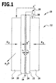
- An exemplary embodiment of a fuel cell 10 comprises an electrode-membrane unit 12.
- the electrode-membrane unit 12 has a cathode 14, an anode 16 and a proton-conducting membrane device 18, which is arranged between the anode 14 and the cathode 16.
- the fuel cell 10 is in particular a PEFC (Proton Exchange Membrane Fuel Cell) type.
- the cathode 14 is supplied to oxidizer in the form of pure oxygen or atmospheric oxygen.
- the anode 16 is supplied gaseous fuel and in particular hydrogen.
- the membrane device serves as an electrolyte, as a carrier for the cathode 14 and the anode 16 and as a separator for the gaseous reactants.
- the partial reaction is running H 2 ⁇ 2 H + + 2 e - from.
- the cathode the partial reaction runs 2 ⁇ H + + 1 2 ⁇ O 2 + 2 ⁇ e - ⁇ H 2 ⁇ O from.
- the membrane device 18 comprises a first membrane layer 20, which borders on the cathode 14.
- the cathode 14 is arranged on the first membrane layer 20.
- the membrane device 18 comprises a second membrane layer 22, which adjoins the anode 16.
- the anode 16 is arranged on the second membrane layer 22.
- the first membrane layer 20 and the second membrane layer 22 are formed proton-conducting; for example, they are based on a perfluorinated, sulfonated polymer.
- One possible material for the first membrane layer 20 and the second membrane layer 22 is, for example, Nafion.
- a catalytic intermediate layer 24 is arranged between the first membrane layer 20 and the second membrane layer 22.
- This is made of a catalyst material such as platinum or platinum-ruthenium.
- the catalyst material may also be carbon supported.
- the catalytic intermediate layer 24 is produced in particular by spraying onto the first membrane layer 20 or the second membrane layer 22.
- the catalytic interlayer preferably has a substantially uniform thickness (based on the connection direction between the cathode 14 and the anode 16). As a result, the first membrane layer 20 and the second membrane layer 22 are aligned substantially parallel to one another.
- a typical thickness of the catalytic intermediate layer 24 is approximately 1 ⁇ m to 5 ⁇ m.
- the catalytic intermediate layer 24 preferably extends over the entire cross-sectional area of the first membrane layer 20 and the second membrane layer 22, wherein the cross-sectional area is transverse to the connecting direction between the cathode 14 and the anode 16. This means that the reaction gas entering the membrane device can not bypass the catalytic intermediate layer 24.
- membranes of a fuel cell 10 of the PEFC type are only proton conductive when moistened. Often, the water produced during the catalytic reaction is not sufficient for moistening a membrane, in particular at temperatures above 100 ° C. From the prior art it is known that reaction gases (oxidizer and / or gaseous fuel) are additionally moistened.
- the catalytic intermediate layer 24 forms an integrated humidifying device of the electrode-membrane unit 12.
- her catalytic hydrogen and oxygen can be converted to water, whereby the first membrane layer 20 and the second membrane layer 22 are moistened from the inside out.
- the catalytic intermediate layer 24 is proton-conducting and electrically separated from the electrodes via the first membrane layer 20 and the second membrane layer 22.
- the actual fuel cell reaction to which the reaction equations have been given above, is not hindered.
- the catalytic intermediate layer 24 is further ensured that reaction gases which diffuse through the first membrane layer 20 (oxidizer) or through the Diffuse second membrane layer 22 (fuel) can abreagieren and thus can not get to the other electrode (fuel to the cathode 14, oxidizer to the anode 16).
- a mixed potential formation and a concomitant lowering of the rest potential is prevented.
- the catalytic intermediate layer 24 can be produced in a simple manner by producing the first membrane layer 20 and the second membrane layer 22 separately and then producing the catalytic intermediate layer 24 on one of the membrane layers 20 or 22, for example by spraying and then the other membrane layer 22 or 20 is positioned on the catalytic liner 24.
- the first membrane layer 20 is permeable to the oxidizer (in addition to the existing diffusion permeability) to facilitate oxidant transport to the catalytic spacer 24. Such an increased permeability can take place, for example, via corresponding perforation of the first membrane layer 20.
- the thickness of the first membrane layer 20 (based on the spacing direction between the cathode 14 and the anode 16) is smaller than the thickness of the second membrane layer 22. This improves the oxidant access to the catalytic intermediate layer 24.
- the catalytic intermediate layer 24 is electrically connected to the cathode 14 or the anode 16. It may be, for example, a short-circuit connection. It can also be used by protons for recombination. When connected to the cathode 14, the proton conduction may be improved.
- the catalytic intermediate layer 24 is connected to the anode 16 via a connecting device 26. This can increase water production.
- connection device 26 may comprise an adjustable resistance device 28.
- the resistance value of the resistance device 28 By adjusting the resistance value of the resistance device 28, the electric current flowing between the anode 16 and the catalytic interlayer 24 can be adjusted. This in turn allows the water formation on the catalytic intermediate layer 24 to be adjusted to a certain extent. As a result, an adaptation to the external conditions is possible; For example, a temperature adjustment is possible. Thus, at higher temperatures, the formation of water can be increased.
- the resistance device 28 it is fundamentally possible for the resistance device 28 to be designed to be temperature-sensitive in such a way that the resistance value decreases when the temperature increases, so that a larger current flows between the anode 16 and the catalytic intermediate layer 24 when the temperature increases. As a result, water formation is increased when the temperature increases.
- a control and in particular automatic control of the humidification of the membrane device 18 can be performed.
Landscapes
- Life Sciences & Earth Sciences (AREA)
- Engineering & Computer Science (AREA)
- Manufacturing & Machinery (AREA)
- Sustainable Development (AREA)
- Sustainable Energy (AREA)
- Chemical & Material Sciences (AREA)
- Chemical Kinetics & Catalysis (AREA)
- Electrochemistry (AREA)
- General Chemical & Material Sciences (AREA)
- Inert Electrodes (AREA)
- Fuel Cell (AREA)
Claims (18)
- Unité de membrane d'électrodes pour une cellule à combustible (10) actionnée avec du combustible sous forme de gaz, comprenant une cathode (14), une anode (16) et un dispositif de membrane conducteur de protons (18) qui est disposé entre l'anode (16) et la cathode (14), le dispositif de membrane (18) comprenant au moins une couche intermédiaire catalytique (24) au niveau de laquelle de l'eau peut être produite par une réaction catalytique d'oxydant et de combustible,
caractérisée en ce que l'au moins une couche intermédiaire catalytique (24) est reliée électriquement à l'anode (16) par l'intermédiaire d'un dispositif de résistance (28). - Unité de membrane d'électrodes selon la revendication 1, caractérisée en ce que le dispositif de membrane (18) présente une structure multicouche avec une première couche de membrane (20) jouxtant la cathode (14), une seconde couche de membrane (22) jouxtant l'anode (16), et l'au moins une couche intermédiaire catalytique (24).
- Unité de membrane d'électrodes selon la revendication 2, caractérisée en ce qu'une seule couche intermédiaire catalytique (24) est agencée entre la première couche de membrane (20) et la seconde couche de membrane (22) et jouxte respectivement celles-ci.
- Unité de membrane d'électrodes selon la revendication 3, caractérisée en ce que la première couche de membrane (20) présente une épaisseur inférieure à celle de la seconde couche de membrane (22).
- Unité de membrane d'électrodes selon l'une des revendications précédentes, caractérisée en ce que l'au moins une couche intermédiaire catalytique (24) s'étend sur toute la surface de la section transversale du dispositif de membrane (18) en diagonale par rapport à la direction de liaison entre la cathode (14) et l'anode (16).
- Unité de membrane d'électrodes selon l'une des revendications précédentes, caractérisée en ce que l'au moins une couche intermédiaire catalytique (24) est fabriquée par vaporisation.
- Unité de membrane d'électrodes selon l'une des revendications précédentes, caractérisée en ce que le dispositif de membrane (18) est formé perméable à l'oxydant par rapport à au moins une couche intermédiaire catalytique (24).
- Unité de membrane d'électrodes selon la revendication 7, caractérisée en ce que le dispositif de membrane (18) est formé perforé.
- Unité de membrane d'électrodes selon la revendication 7 ou 8, caractérisée en ce qu'une première couche de membrane (20) agencée entre la cathode (14) et l'au moins une couche intermédiaire catalytique (24) est formée perméable à l'oxydant.
- Unité de membrane d'électrodes selon l'une des revendications précédentes, caractérisée en ce que le dispositif de résistance (28) est formé réglable sur le plan de sa valeur de résistance.
- Unité de membrane d'électrodes selon l'une des revendications précédentes, caractérisée en ce que le dispositif de résistance (28) est formé sensible à la température sur le plan de sa valeur de résistance.
- Unité de membrane d'électrodes selon l'une des revendications précédentes, caractérisée en ce que l'épaisseur de l'au moins une couche intermédiaire catalytique (24) est de l'ordre du micromètre.
- Unité de membrane d'électrodes selon l'une des revendications précédentes, caractérisée en ce que la couche intermédiaire catalytique (24) est conductrice de protons.
- Unité de membrane d'électrodes selon l'une des revendications précédentes, caractérisée en ce que le combustible est de l'hydrogène.
- Unité de membrane d'électrodes selon l'une des revendications précédentes, caractérisée en ce que l'au moins une couche intermédiaire catalytique (24) est fabriquée en un matériau de catalyseur.
- Utilisation d'une unité de membrane d'électrodes selon l'une des revendications précédentes dans une cellule à combustible.
- Cellule à combustible comprenant une unité de membrane d'électrodes selon l'une des revendications 1 à 15.
- Cellule à combustible selon la revendication 17, qui est une cellule à combustible à électrolyte polymère (PEFC).
Applications Claiming Priority (1)
| Application Number | Priority Date | Filing Date | Title |
|---|---|---|---|
| DE102006012908A DE102006012908A1 (de) | 2006-03-10 | 2006-03-10 | Elektroden-Membran-Einheit und Brennstoffzelle |
Publications (3)
| Publication Number | Publication Date |
|---|---|
| EP1833112A2 EP1833112A2 (fr) | 2007-09-12 |
| EP1833112A3 EP1833112A3 (fr) | 2008-05-14 |
| EP1833112B1 true EP1833112B1 (fr) | 2010-12-22 |
Family
ID=38134727
Family Applications (1)
| Application Number | Title | Priority Date | Filing Date |
|---|---|---|---|
| EP07103566A Not-in-force EP1833112B1 (fr) | 2006-03-10 | 2007-03-06 | Unité de membrane d'électrodes et cellule combustible |
Country Status (4)
| Country | Link |
|---|---|
| EP (1) | EP1833112B1 (fr) |
| AT (1) | ATE492919T1 (fr) |
| DE (2) | DE102006012908A1 (fr) |
| DK (1) | DK1833112T3 (fr) |
Cited By (1)
| Publication number | Priority date | Publication date | Assignee | Title |
|---|---|---|---|---|
| EP3922757A1 (fr) * | 2016-12-22 | 2021-12-15 | Johnson Matthey Fuel Cells Limited | Membrane enduite de catalyseur ayant une structure stratifiée |
Families Citing this family (2)
| Publication number | Priority date | Publication date | Assignee | Title |
|---|---|---|---|---|
| DE102006041961B4 (de) * | 2006-08-30 | 2010-01-28 | Deutsches Zentrum für Luft- und Raumfahrt e.V. | Elektroden-Membran-Einheit, ihre Verwendung und Brennstoffzelle |
| US7858915B2 (en) | 2008-03-31 | 2010-12-28 | Eastman Kodak Company | Active pixel sensor having two wafers |
Family Cites Families (4)
| Publication number | Priority date | Publication date | Assignee | Title |
|---|---|---|---|---|
| US5672439A (en) * | 1995-12-18 | 1997-09-30 | Ballard Power Systems, Inc. | Method and apparatus for reducing reactant crossover in an electrochemical fuel cell |
| DE19917812C2 (de) * | 1999-04-20 | 2002-11-21 | Siemens Ag | Membranelektrodeneinheit für eine selbstbefeuchtende Brennstoffzelle, Verfahren zu ihrer Herstellung und Brennstoffzellenbatterie mit einer solchen Membranelektrodeneinheit |
| US7507494B2 (en) * | 2004-03-04 | 2009-03-24 | Utc Power Corporation | Extended catalyzed layer for minimizing cross-over oxygen and consuming peroxide |
| JP2005332693A (ja) * | 2004-05-20 | 2005-12-02 | Aisin Seiki Co Ltd | 燃料電池 |
-
2006
- 2006-03-10 DE DE102006012908A patent/DE102006012908A1/de not_active Ceased
-
2007
- 2007-03-06 DE DE502007005998T patent/DE502007005998D1/de active Active
- 2007-03-06 AT AT07103566T patent/ATE492919T1/de active
- 2007-03-06 DK DK07103566.1T patent/DK1833112T3/da active
- 2007-03-06 EP EP07103566A patent/EP1833112B1/fr not_active Not-in-force
Cited By (1)
| Publication number | Priority date | Publication date | Assignee | Title |
|---|---|---|---|---|
| EP3922757A1 (fr) * | 2016-12-22 | 2021-12-15 | Johnson Matthey Fuel Cells Limited | Membrane enduite de catalyseur ayant une structure stratifiée |
Also Published As
| Publication number | Publication date |
|---|---|
| EP1833112A3 (fr) | 2008-05-14 |
| DE502007005998D1 (de) | 2011-02-03 |
| DK1833112T3 (da) | 2011-04-11 |
| DE102006012908A1 (de) | 2007-09-13 |
| ATE492919T1 (de) | 2011-01-15 |
| EP1833112A2 (fr) | 2007-09-12 |
Similar Documents
| Publication | Publication Date | Title |
|---|---|---|
| EP1759434B1 (fr) | Module membrane-electrode (mea) pour pile a combustible | |
| DE102008046403B4 (de) | Sauerstoffentwicklungsreaktionskatalysatoren enthaltende Elektroden | |
| WO1998021777A1 (fr) | Unite electrodes-electrolyte pour une pile a combustible | |
| DE102008038202B4 (de) | PEM-Brennstoffzelle mit verbessertem Wassermanagement und Verfahren zu ihrer Herstellung | |
| DE112008001766B4 (de) | Elektrolytmembran und Brennstoffzelle unter Verwendung derselben | |
| DE112013004009T5 (de) | Verfahren zur Herstellung eines katalytischen Materials | |
| DE112005001340B4 (de) | Zellenmodul und Brennstoffzelle | |
| DE112005002022B4 (de) | Membran-Elektroden-Einheit und Brennstoffzelle | |
| EP1833112B1 (fr) | Unité de membrane d'électrodes et cellule combustible | |
| DE102011014154B4 (de) | Strömungsfeldplatte für Brennstoffzellenanwendungen | |
| DE102016220653A1 (de) | Korrosionsbeständiger katalysator | |
| DE102021204371A1 (de) | Reversible shunts zum schutz vor überladung in polymerelektrolytmembran-brennstoffzellen | |
| EP3834243B1 (fr) | Structure en couches pour une pile à combustible et procédé pour fabriquer une telle structure en couches | |
| DE102006041961B4 (de) | Elektroden-Membran-Einheit, ihre Verwendung und Brennstoffzelle | |
| EP2618417B1 (fr) | Pile à combustible directe à méthanol et procédé de fonctionnement de celle-ci | |
| DE112006002510B4 (de) | Brennstoffzelle | |
| DE112007002008B4 (de) | Brennstoffzelle | |
| DE102014118309A1 (de) | Schichtauslegung, um eine Korrosion von Brennstoffzellenelektroden aus einem nicht idealen Betrieb zu mindern | |
| EP1833113B1 (fr) | Unité membrane-électrodes et pile à combustible | |
| DE202005008749U1 (de) | Membran-Elektroden-Modul (MEA) für eine Brennstoffzelle | |
| DE102012011441A1 (de) | Membran-Elektroden-Einheit für eine Brennstoffzelle | |
| DE10260501A1 (de) | Gasdiffusionselektrode mit einer Schicht zur Steuerung der Querdiffusion von Wasser | |
| EP2913877B1 (fr) | Pile à combustible à méthanol direct et empilement de piles à combustible à méthanol direct avec élimination efficace du CO2 et procédé d'utilisation d'une telle pile à combustible à méthanol direct | |
| DE102020102709A1 (de) | Verfahren zur Herstellung einer Membranelektrodenanordnung, Membranelektrodenanordnung sowie Brennstoffzelle | |
| DE102020106082A1 (de) | Verfahren zur Herstellung einer Brennstoffzelle, Vorrichtung zur Herstellung einer Membranelektrodenanordnung für eine Brennstoffzelle, Brennstoffzelle sowie Brennstoffzellenstapel |
Legal Events
| Date | Code | Title | Description |
|---|---|---|---|
| PUAI | Public reference made under article 153(3) epc to a published international application that has entered the european phase |
Free format text: ORIGINAL CODE: 0009012 |
|
| AK | Designated contracting states |
Kind code of ref document: A2 Designated state(s): AT BE BG CH CY CZ DE DK EE ES FI FR GB GR HU IE IS IT LI LT LU LV MC MT NL PL PT RO SE SI SK TR |
|
| AX | Request for extension of the european patent |
Extension state: AL BA HR MK YU |
|
| PUAL | Search report despatched |
Free format text: ORIGINAL CODE: 0009013 |
|
| AK | Designated contracting states |
Kind code of ref document: A3 Designated state(s): AT BE BG CH CY CZ DE DK EE ES FI FR GB GR HU IE IS IT LI LT LU LV MC MT NL PL PT RO SE SI SK TR |
|
| AX | Request for extension of the european patent |
Extension state: AL BA HR MK RS |
|
| RIC1 | Information provided on ipc code assigned before grant |
Ipc: H01M 8/04 20060101AFI20080404BHEP |
|
| 17P | Request for examination filed |
Effective date: 20081108 |
|
| AKX | Designation fees paid |
Designated state(s): AT BE BG CH CY CZ DE DK EE ES FI FR GB GR HU IE IS IT LI LT LU LV MC MT NL PL PT RO SE SI SK TR |
|
| 17Q | First examination report despatched |
Effective date: 20090108 |
|
| GRAP | Despatch of communication of intention to grant a patent |
Free format text: ORIGINAL CODE: EPIDOSNIGR1 |
|
| GRAS | Grant fee paid |
Free format text: ORIGINAL CODE: EPIDOSNIGR3 |
|
| GRAA | (expected) grant |
Free format text: ORIGINAL CODE: 0009210 |
|
| AK | Designated contracting states |
Kind code of ref document: B1 Designated state(s): AT BE BG CH CY CZ DE DK EE ES FI FR GB GR HU IE IS IT LI LT LU LV MC MT NL PL PT RO SE SI SK TR |
|
| REG | Reference to a national code |
Ref country code: GB Ref legal event code: FG4D Free format text: NOT ENGLISH |
|
| REG | Reference to a national code |
Ref country code: CH Ref legal event code: EP |
|
| REG | Reference to a national code |
Ref country code: IE Ref legal event code: FG4D |
|
| REF | Corresponds to: |
Ref document number: 502007005998 Country of ref document: DE Date of ref document: 20110203 Kind code of ref document: P |
|
| REG | Reference to a national code |
Ref country code: DE Ref legal event code: R096 Ref document number: 502007005998 Country of ref document: DE Effective date: 20110203 |
|
| REG | Reference to a national code |
Ref country code: DK Ref legal event code: T3 |
|
| REG | Reference to a national code |
Ref country code: NL Ref legal event code: VDEP Effective date: 20101222 |
|
| PG25 | Lapsed in a contracting state [announced via postgrant information from national office to epo] |
Ref country code: LT Free format text: LAPSE BECAUSE OF FAILURE TO SUBMIT A TRANSLATION OF THE DESCRIPTION OR TO PAY THE FEE WITHIN THE PRESCRIBED TIME-LIMIT Effective date: 20101222 |
|
| LTIE | Lt: invalidation of european patent or patent extension |
Effective date: 20101222 |
|
| PG25 | Lapsed in a contracting state [announced via postgrant information from national office to epo] |
Ref country code: BG Free format text: LAPSE BECAUSE OF FAILURE TO SUBMIT A TRANSLATION OF THE DESCRIPTION OR TO PAY THE FEE WITHIN THE PRESCRIBED TIME-LIMIT Effective date: 20110322 Ref country code: FI Free format text: LAPSE BECAUSE OF FAILURE TO SUBMIT A TRANSLATION OF THE DESCRIPTION OR TO PAY THE FEE WITHIN THE PRESCRIBED TIME-LIMIT Effective date: 20101222 Ref country code: SE Free format text: LAPSE BECAUSE OF FAILURE TO SUBMIT A TRANSLATION OF THE DESCRIPTION OR TO PAY THE FEE WITHIN THE PRESCRIBED TIME-LIMIT Effective date: 20101222 Ref country code: LV Free format text: LAPSE BECAUSE OF FAILURE TO SUBMIT A TRANSLATION OF THE DESCRIPTION OR TO PAY THE FEE WITHIN THE PRESCRIBED TIME-LIMIT Effective date: 20101222 Ref country code: CY Free format text: LAPSE BECAUSE OF FAILURE TO SUBMIT A TRANSLATION OF THE DESCRIPTION OR TO PAY THE FEE WITHIN THE PRESCRIBED TIME-LIMIT Effective date: 20101222 Ref country code: SI Free format text: LAPSE BECAUSE OF FAILURE TO SUBMIT A TRANSLATION OF THE DESCRIPTION OR TO PAY THE FEE WITHIN THE PRESCRIBED TIME-LIMIT Effective date: 20101222 |
|
| REG | Reference to a national code |
Ref country code: IE Ref legal event code: FD4D |
|
| PG25 | Lapsed in a contracting state [announced via postgrant information from national office to epo] |
Ref country code: GR Free format text: LAPSE BECAUSE OF FAILURE TO SUBMIT A TRANSLATION OF THE DESCRIPTION OR TO PAY THE FEE WITHIN THE PRESCRIBED TIME-LIMIT Effective date: 20110323 Ref country code: ES Free format text: LAPSE BECAUSE OF FAILURE TO SUBMIT A TRANSLATION OF THE DESCRIPTION OR TO PAY THE FEE WITHIN THE PRESCRIBED TIME-LIMIT Effective date: 20110402 Ref country code: PT Free format text: LAPSE BECAUSE OF FAILURE TO SUBMIT A TRANSLATION OF THE DESCRIPTION OR TO PAY THE FEE WITHIN THE PRESCRIBED TIME-LIMIT Effective date: 20110422 Ref country code: CZ Free format text: LAPSE BECAUSE OF FAILURE TO SUBMIT A TRANSLATION OF THE DESCRIPTION OR TO PAY THE FEE WITHIN THE PRESCRIBED TIME-LIMIT Effective date: 20101222 Ref country code: EE Free format text: LAPSE BECAUSE OF FAILURE TO SUBMIT A TRANSLATION OF THE DESCRIPTION OR TO PAY THE FEE WITHIN THE PRESCRIBED TIME-LIMIT Effective date: 20101222 Ref country code: IS Free format text: LAPSE BECAUSE OF FAILURE TO SUBMIT A TRANSLATION OF THE DESCRIPTION OR TO PAY THE FEE WITHIN THE PRESCRIBED TIME-LIMIT Effective date: 20110422 |
|
| PG25 | Lapsed in a contracting state [announced via postgrant information from national office to epo] |
Ref country code: SK Free format text: LAPSE BECAUSE OF FAILURE TO SUBMIT A TRANSLATION OF THE DESCRIPTION OR TO PAY THE FEE WITHIN THE PRESCRIBED TIME-LIMIT Effective date: 20101222 Ref country code: RO Free format text: LAPSE BECAUSE OF FAILURE TO SUBMIT A TRANSLATION OF THE DESCRIPTION OR TO PAY THE FEE WITHIN THE PRESCRIBED TIME-LIMIT Effective date: 20101222 Ref country code: PL Free format text: LAPSE BECAUSE OF FAILURE TO SUBMIT A TRANSLATION OF THE DESCRIPTION OR TO PAY THE FEE WITHIN THE PRESCRIBED TIME-LIMIT Effective date: 20101222 Ref country code: NL Free format text: LAPSE BECAUSE OF FAILURE TO SUBMIT A TRANSLATION OF THE DESCRIPTION OR TO PAY THE FEE WITHIN THE PRESCRIBED TIME-LIMIT Effective date: 20101222 |
|
| BERE | Be: lapsed |
Owner name: DEUTSCHES ZENTRUM FUR LUFT- UND RAUMFAHRT E.V. Effective date: 20110331 |
|
| PLBE | No opposition filed within time limit |
Free format text: ORIGINAL CODE: 0009261 |
|
| STAA | Information on the status of an ep patent application or granted ep patent |
Free format text: STATUS: NO OPPOSITION FILED WITHIN TIME LIMIT |
|
| PG25 | Lapsed in a contracting state [announced via postgrant information from national office to epo] |
Ref country code: IE Free format text: LAPSE BECAUSE OF FAILURE TO SUBMIT A TRANSLATION OF THE DESCRIPTION OR TO PAY THE FEE WITHIN THE PRESCRIBED TIME-LIMIT Effective date: 20101222 Ref country code: MC Free format text: LAPSE BECAUSE OF NON-PAYMENT OF DUE FEES Effective date: 20110331 |
|
| REG | Reference to a national code |
Ref country code: CH Ref legal event code: PL |
|
| 26N | No opposition filed |
Effective date: 20110923 |
|
| PG25 | Lapsed in a contracting state [announced via postgrant information from national office to epo] |
Ref country code: MT Free format text: LAPSE BECAUSE OF FAILURE TO SUBMIT A TRANSLATION OF THE DESCRIPTION OR TO PAY THE FEE WITHIN THE PRESCRIBED TIME-LIMIT Effective date: 20101222 Ref country code: IT Free format text: LAPSE BECAUSE OF FAILURE TO SUBMIT A TRANSLATION OF THE DESCRIPTION OR TO PAY THE FEE WITHIN THE PRESCRIBED TIME-LIMIT Effective date: 20101222 Ref country code: BE Free format text: LAPSE BECAUSE OF NON-PAYMENT OF DUE FEES Effective date: 20110331 |
|
| REG | Reference to a national code |
Ref country code: DE Ref legal event code: R097 Ref document number: 502007005998 Country of ref document: DE Effective date: 20110923 |
|
| PG25 | Lapsed in a contracting state [announced via postgrant information from national office to epo] |
Ref country code: CH Free format text: LAPSE BECAUSE OF NON-PAYMENT OF DUE FEES Effective date: 20110331 Ref country code: LI Free format text: LAPSE BECAUSE OF NON-PAYMENT OF DUE FEES Effective date: 20110331 |
|
| REG | Reference to a national code |
Ref country code: AT Ref legal event code: MM01 Ref document number: 492919 Country of ref document: AT Kind code of ref document: T Effective date: 20120306 |
|
| PG25 | Lapsed in a contracting state [announced via postgrant information from national office to epo] |
Ref country code: LU Free format text: LAPSE BECAUSE OF NON-PAYMENT OF DUE FEES Effective date: 20110306 |
|
| PG25 | Lapsed in a contracting state [announced via postgrant information from national office to epo] |
Ref country code: AT Free format text: LAPSE BECAUSE OF NON-PAYMENT OF DUE FEES Effective date: 20120306 |
|
| PG25 | Lapsed in a contracting state [announced via postgrant information from national office to epo] |
Ref country code: TR Free format text: LAPSE BECAUSE OF FAILURE TO SUBMIT A TRANSLATION OF THE DESCRIPTION OR TO PAY THE FEE WITHIN THE PRESCRIBED TIME-LIMIT Effective date: 20101222 |
|
| PG25 | Lapsed in a contracting state [announced via postgrant information from national office to epo] |
Ref country code: HU Free format text: LAPSE BECAUSE OF FAILURE TO SUBMIT A TRANSLATION OF THE DESCRIPTION OR TO PAY THE FEE WITHIN THE PRESCRIBED TIME-LIMIT Effective date: 20101222 |
|
| REG | Reference to a national code |
Ref country code: FR Ref legal event code: PLFP Year of fee payment: 9 |
|
| REG | Reference to a national code |
Ref country code: DE Ref legal event code: R082 Ref document number: 502007005998 Country of ref document: DE Representative=s name: HOEGER, STELLRECHT & PARTNER PATENTANWAELTE MB, DE |
|
| REG | Reference to a national code |
Ref country code: FR Ref legal event code: PLFP Year of fee payment: 10 |
|
| REG | Reference to a national code |
Ref country code: FR Ref legal event code: PLFP Year of fee payment: 11 |
|
| REG | Reference to a national code |
Ref country code: FR Ref legal event code: PLFP Year of fee payment: 12 |
|
| PGFP | Annual fee paid to national office [announced via postgrant information from national office to epo] |
Ref country code: GB Payment date: 20190227 Year of fee payment: 13 Ref country code: DE Payment date: 20190215 Year of fee payment: 13 |
|
| PGFP | Annual fee paid to national office [announced via postgrant information from national office to epo] |
Ref country code: FR Payment date: 20190220 Year of fee payment: 13 Ref country code: DE Payment date: 20190215 Year of fee payment: 13 Ref country code: DK Payment date: 20190227 Year of fee payment: 13 |
|
| REG | Reference to a national code |
Ref country code: DE Ref legal event code: R082 Ref document number: 502007005998 Country of ref document: DE Representative=s name: HOEGER, STELLRECHT & PARTNER PATENTANWAELTE MB, DE |
|
| REG | Reference to a national code |
Ref country code: DE Ref legal event code: R119 Ref document number: 502007005998 Country of ref document: DE |
|
| REG | Reference to a national code |
Ref country code: DK Ref legal event code: EBP Effective date: 20200331 |
|
| PG25 | Lapsed in a contracting state [announced via postgrant information from national office to epo] |
Ref country code: FR Free format text: LAPSE BECAUSE OF NON-PAYMENT OF DUE FEES Effective date: 20200331 Ref country code: DE Free format text: LAPSE BECAUSE OF NON-PAYMENT OF DUE FEES Effective date: 20201001 |
|
| GBPC | Gb: european patent ceased through non-payment of renewal fee |
Effective date: 20200306 |
|
| PG25 | Lapsed in a contracting state [announced via postgrant information from national office to epo] |
Ref country code: DK Free format text: LAPSE BECAUSE OF NON-PAYMENT OF DUE FEES Effective date: 20200331 Ref country code: GB Free format text: LAPSE BECAUSE OF NON-PAYMENT OF DUE FEES Effective date: 20200306 |