EP1832895B1 - Verfahren zur Detektierung von Bewegungen in der Nähe von automatischen Türen - Google Patents
Verfahren zur Detektierung von Bewegungen in der Nähe von automatischen Türen Download PDFInfo
- Publication number
- EP1832895B1 EP1832895B1 EP07109302A EP07109302A EP1832895B1 EP 1832895 B1 EP1832895 B1 EP 1832895B1 EP 07109302 A EP07109302 A EP 07109302A EP 07109302 A EP07109302 A EP 07109302A EP 1832895 B1 EP1832895 B1 EP 1832895B1
- Authority
- EP
- European Patent Office
- Prior art keywords
- antenna
- doppler
- detection
- automatic doors
- movements around
- Prior art date
- Legal status (The legal status is an assumption and is not a legal conclusion. Google has not performed a legal analysis and makes no representation as to the accuracy of the status listed.)
- Expired - Lifetime
Links
- 238000000034 method Methods 0.000 title claims description 28
- 230000033001 locomotion Effects 0.000 title claims description 21
- 238000001514 detection method Methods 0.000 claims description 46
- 238000012545 processing Methods 0.000 claims description 9
- 238000005070 sampling Methods 0.000 claims description 7
- 230000008569 process Effects 0.000 claims description 5
- 230000005855 radiation Effects 0.000 description 21
- 230000008878 coupling Effects 0.000 description 9
- 238000010168 coupling process Methods 0.000 description 9
- 238000005859 coupling reaction Methods 0.000 description 9
- 230000010287 polarization Effects 0.000 description 7
- 239000011358 absorbing material Substances 0.000 description 5
- 230000008901 benefit Effects 0.000 description 4
- 230000008859 change Effects 0.000 description 4
- 238000003491 array Methods 0.000 description 2
- 238000013461 design Methods 0.000 description 2
- 238000010586 diagram Methods 0.000 description 2
- 238000005516 engineering process Methods 0.000 description 2
- 238000002955 isolation Methods 0.000 description 2
- 238000004088 simulation Methods 0.000 description 2
- 239000000758 substrate Substances 0.000 description 2
- 230000001360 synchronised effect Effects 0.000 description 2
- 230000009471 action Effects 0.000 description 1
- 230000004075 alteration Effects 0.000 description 1
- 238000004458 analytical method Methods 0.000 description 1
- 230000005540 biological transmission Effects 0.000 description 1
- 239000003990 capacitor Substances 0.000 description 1
- 230000001419 dependent effect Effects 0.000 description 1
- 230000000694 effects Effects 0.000 description 1
- 238000007667 floating Methods 0.000 description 1
- 239000006260 foam Substances 0.000 description 1
- 239000000463 material Substances 0.000 description 1
- 238000005259 measurement Methods 0.000 description 1
- 230000004048 modification Effects 0.000 description 1
- 238000012986 modification Methods 0.000 description 1
- 238000012544 monitoring process Methods 0.000 description 1
- 230000005693 optoelectronics Effects 0.000 description 1
- 230000003071 parasitic effect Effects 0.000 description 1
- 230000002265 prevention Effects 0.000 description 1
- 230000007704 transition Effects 0.000 description 1
Images

Classifications
-
- H—ELECTRICITY
- H01—ELECTRIC ELEMENTS
- H01Q—ANTENNAS, i.e. RADIO AERIALS
- H01Q1/00—Details of, or arrangements associated with, antennas
- H01Q1/12—Supports; Mounting means
- H01Q1/22—Supports; Mounting means by structural association with other equipment or articles
-
- H—ELECTRICITY
- H01—ELECTRIC ELEMENTS
- H01Q—ANTENNAS, i.e. RADIO AERIALS
- H01Q13/00—Waveguide horns or mouths; Slot antennas; Leaky-waveguide antennas; Equivalent structures causing radiation along the transmission path of a guided wave
-
- G—PHYSICS
- G01—MEASURING; TESTING
- G01S—RADIO DIRECTION-FINDING; RADIO NAVIGATION; DETERMINING DISTANCE OR VELOCITY BY USE OF RADIO WAVES; LOCATING OR PRESENCE-DETECTING BY USE OF THE REFLECTION OR RERADIATION OF RADIO WAVES; ANALOGOUS ARRANGEMENTS USING OTHER WAVES
- G01S13/00—Systems using the reflection or reradiation of radio waves, e.g. radar systems; Analogous systems using reflection or reradiation of waves whose nature or wavelength is irrelevant or unspecified
- G01S13/02—Systems using reflection of radio waves, e.g. primary radar systems; Analogous systems
- G01S13/50—Systems of measurement based on relative movement of target
- G01S13/52—Discriminating between fixed and moving objects or between objects moving at different speeds
- G01S13/56—Discriminating between fixed and moving objects or between objects moving at different speeds for presence detection
-
- H—ELECTRICITY
- H01—ELECTRIC ELEMENTS
- H01Q—ANTENNAS, i.e. RADIO AERIALS
- H01Q1/00—Details of, or arrangements associated with, antennas
- H01Q1/12—Supports; Mounting means
- H01Q1/22—Supports; Mounting means by structural association with other equipment or articles
- H01Q1/24—Supports; Mounting means by structural association with other equipment or articles with receiving set
- H01Q1/247—Supports; Mounting means by structural association with other equipment or articles with receiving set with frequency mixer, e.g. for direct satellite reception or Doppler radar
-
- H—ELECTRICITY
- H01—ELECTRIC ELEMENTS
- H01Q—ANTENNAS, i.e. RADIO AERIALS
- H01Q21/00—Antenna arrays or systems
- H01Q21/06—Arrays of individually energised antenna units similarly polarised and spaced apart
- H01Q21/061—Two dimensional planar arrays
- H01Q21/065—Patch antenna array
-
- H—ELECTRICITY
- H01—ELECTRIC ELEMENTS
- H01Q—ANTENNAS, i.e. RADIO AERIALS
- H01Q3/00—Arrangements for changing or varying the orientation or the shape of the directional pattern of the waves radiated from an antenna or antenna system
- H01Q3/24—Arrangements for changing or varying the orientation or the shape of the directional pattern of the waves radiated from an antenna or antenna system varying the orientation by switching energy from one active radiating element to another, e.g. for beam switching
-
- E—FIXED CONSTRUCTIONS
- E05—LOCKS; KEYS; WINDOW OR DOOR FITTINGS; SAFES
- E05F—DEVICES FOR MOVING WINGS INTO OPEN OR CLOSED POSITION; CHECKS FOR WINGS; WING FITTINGS NOT OTHERWISE PROVIDED FOR, CONCERNED WITH THE FUNCTIONING OF THE WING
- E05F15/00—Power-operated mechanisms for wings
- E05F15/70—Power-operated mechanisms for wings with automatic actuation
- E05F15/73—Power-operated mechanisms for wings with automatic actuation responsive to movement or presence of persons or objects
-
- E—FIXED CONSTRUCTIONS
- E05—LOCKS; KEYS; WINDOW OR DOOR FITTINGS; SAFES
- E05Y—INDEXING SCHEME ASSOCIATED WITH SUBCLASSES E05D AND E05F, RELATING TO CONSTRUCTION ELEMENTS, ELECTRIC CONTROL, POWER SUPPLY, POWER SIGNAL OR TRANSMISSION, USER INTERFACES, MOUNTING OR COUPLING, DETAILS, ACCESSORIES, AUXILIARY OPERATIONS NOT OTHERWISE PROVIDED FOR, APPLICATION THEREOF
- E05Y2400/00—Electronic control; Electrical power; Power supply; Power or signal transmission; User interfaces
- E05Y2400/10—Electronic control
- E05Y2400/52—Safety arrangements associated with the wing motor
- E05Y2400/53—Wing impact prevention or reduction
- E05Y2400/54—Obstruction or resistance detection
-
- E—FIXED CONSTRUCTIONS
- E05—LOCKS; KEYS; WINDOW OR DOOR FITTINGS; SAFES
- E05Y—INDEXING SCHEME ASSOCIATED WITH SUBCLASSES E05D AND E05F, RELATING TO CONSTRUCTION ELEMENTS, ELECTRIC CONTROL, POWER SUPPLY, POWER SIGNAL OR TRANSMISSION, USER INTERFACES, MOUNTING OR COUPLING, DETAILS, ACCESSORIES, AUXILIARY OPERATIONS NOT OTHERWISE PROVIDED FOR, APPLICATION THEREOF
- E05Y2800/00—Details, accessories and auxiliary operations not otherwise provided for
- E05Y2800/20—Combinations of elements
- E05Y2800/22—Combinations of elements of not identical elements of the same category, e.g. combinations of not identical springs
-
- E—FIXED CONSTRUCTIONS
- E05—LOCKS; KEYS; WINDOW OR DOOR FITTINGS; SAFES
- E05Y—INDEXING SCHEME ASSOCIATED WITH SUBCLASSES E05D AND E05F, RELATING TO CONSTRUCTION ELEMENTS, ELECTRIC CONTROL, POWER SUPPLY, POWER SIGNAL OR TRANSMISSION, USER INTERFACES, MOUNTING OR COUPLING, DETAILS, ACCESSORIES, AUXILIARY OPERATIONS NOT OTHERWISE PROVIDED FOR, APPLICATION THEREOF
- E05Y2900/00—Application of doors, windows, wings or fittings thereof
- E05Y2900/10—Application of doors, windows, wings or fittings thereof for buildings or parts thereof
- E05Y2900/13—Type of wing
- E05Y2900/132—Doors
-
- G—PHYSICS
- G01—MEASURING; TESTING
- G01S—RADIO DIRECTION-FINDING; RADIO NAVIGATION; DETERMINING DISTANCE OR VELOCITY BY USE OF RADIO WAVES; LOCATING OR PRESENCE-DETECTING BY USE OF THE REFLECTION OR RERADIATION OF RADIO WAVES; ANALOGOUS ARRANGEMENTS USING OTHER WAVES
- G01S7/00—Details of systems according to groups G01S13/00, G01S15/00, G01S17/00
- G01S7/02—Details of systems according to groups G01S13/00, G01S15/00, G01S17/00 of systems according to group G01S13/00
- G01S7/024—Details of systems according to groups G01S13/00, G01S15/00, G01S17/00 of systems according to group G01S13/00 using polarisation effects
Definitions
- the invention relates to the method of detecting movements around automatic doors.
- planar antennas are known to use planar antennas. On top of their inherent interesting characteristics of size, cost and radiation performances, these antennas are generally used in all possible cases when an antenna radiation pattern change is required. Often a switching between two distinct configurations of the planar antenna is required. If used as detection antenna, these configurations correspond to two detection or radiation pattern shapes. In order to provide different detection or radiation patterns, it is well known in the art to use two or more antennas. Other techniques consist of changing the detection or radiation pattern of the antenna by the use of absorbing material or metallic surrounding configurations. However, all of these techniques are based on a mechanical modification of the antenna.
- a Doppler Radar sensor for detecting movements around automatic doors.
- This Doppler Radar sensor comprises a microwave circuit board accommodating an oscillator and a mixer, and an antenna board carrying transmit and receive patch arrays.
- the two boards are disposed adjacent one another. Coupling between the microwave circuit and the antenna arrays is achieved by two slots resonant at the oscillator fundamental frequency and formed in ground plane on the microwave board. Feed striplines on the two boards lie orthogonal to the slots and are terminated in T-sections.
- the strip-line/slot arrangement suppresses emission at the oscillator second harmonic frequency.
- the antenna board has no electrical connection to the microwave circuit, enabling the radiated beam shape to be changed by simply replacing the antenna board with one having a different patch array pattern.
- a full planar sensor including an oscillator, transmit antenna, receive antenna, Mixer and Infrared output is disclosed.
- US 5,262,783 is also disclosed a method of detecting movements around automatic doors comprising the method steps: generating a detection pattern and detecting the Doppler signal coming from a moving target within the respective detection pattern according to the preamble of claim 1.
- EP 0 535 780 A1 discloses a radar sensor having a monolithic millimeter wave integrated circuit - MMIC - transceiver is provided having a transmitter for transmitting a frequency modulated signal and a receiver for receiving reflected signals thereof.
- a microstrip patch antenna is provided for transmitting signals within a desired field and receiving the reflected signals from objects therein.
- a digital signal processor is further provided for analyzing the received signal and providing output signals therefrom.
- This sensor is focused on range measurement at Millimeter waves and more precisely on the use of MMIC. The range information is obtained by the use of a FM modulation of the carrier and FFT analysis on the received signal. This technique can be used for detecting the presence of objects by analyzing the profile of the received spot in a given situation compared to another one taken as reference.
- EP 0 780 969 A1 discloses a Doppler radar module having a frequency mixer which has a pair of microstrip lines, coupled to respective diodes at one end and coupled together via a capacitor at the other end.
- the common transmission/reception antenna is coupled to the first end of one microstrip line and an oscillator is coupled to the first end of the second microstrip line.
- the remaining terminals of both diodes are connected to ground, with a phase comparator connected to both microstrip lines at their capacitively coupled ends.
- a Doppler module giving the direction of signal by the use of the two diodes is disclosed. This technique is based on the special way they use to retrieve the Doppler signals out of the Schottky diodes.
- US 5,717,399 discloses a radar device for vehicle use and, more particularly, a radar device for vehicle use which enables various operations including collision prevention or automatic navigation at high speed traveling, cruising in a traffic jam at intermediate or low speed traveling and the detection of an obstacle around a vehicle.
- This radar device comprises PIN diodes, which are selectively switched on and off under the control of a monitoring control section and one planar multiple antenna.
- This antenna is composed of several different antennas that have different directivities and that can be selected as an antenna for transmittin and receiving signals for detecting the target. This means that only one antenna is active at a time.
- US 6,175,723 relates to a self structuring antenna system which comprises a switchable antenna array as planar antenna.
- the antenna array is defined by a plurality of antenna elements that are selectively electrically connectable to each other by a series of switches. This allows the alteration of the physical shape of the antenna array without actually moving or mechanically changing the antenna. By changing the physical shape, the radiation pattern or lobe of the antenna can be altered. Furthermore, the shape of the antenna can be adapted to changing electrical and/or physical environments in order to achieve a good antenna performance.
- the switches are relays, either solid-state, mechanical or opto-electronic, generally mounted behind the antenna itself. Such switches are expensive and difficult to process. Therefore, this antenna structure is too expensive for cost-sensitive applications.
- a typical cost-sensitive application for a planar antenna is an automatic door opener.
- Automatic door openers use door opener sensors which are usually made of waveguide or planar transceivers. However, it is very difficult and expensive to design a switch for different antennas which can be used in waveguide technology. If the antenna is made in planar technology, it is then possible to provide some electrical switching of the radiation pattern more easily.
- a method of detecting movements around automatic doors using a a Doppler Radar comprising the method steps: generating a detection pattern and detecting the Doppler signal coming from a moving target within the respective detection pattern.
- the following method steps are provided: providing at least two electronically selectable detection patterns; selecting the detection patterns; detecting the Doppler signal coming from a moving target within the respective detection patterns ; and processing the Doppler signal in a circuitry in order to calculate a motion direction of the moving target.
- the invention is characterized by performing a high-speed switching between different detection patterns in accordance to an algorithm resulting in a dynamic detection lobe.
- Sampling the respectively obtained Doppler signals for each detection pattern with the circuitry having sample and hold circuits is a further aspect of the invention.
- the sample and hold circuits can be synchronized with the high-speed switching
- processing the at least one Doppler signal by the circuitry having a digital signal processor by the circuitry having a digital signal processor.
- the digital signal processor processes at least two Doppler signals obtained from the sample and hold circuits and corresponding to at least two different detection patterns and calculates from the Doppler signals an intermediate pattern by weighting their respective Doppler signals.
- the circuitry can also comprise an oscillator which produces a sampling frequency signal with accuracy suitable for sampling.
- the circuitry can be formed to perform weighting of the two patterns by pulse width modulation of the Doppler signal. The weighting between the two Doppler signals would be achieved by the meaning action of the amplifier low pass filter. Then, at least one detection chain would be sufficient to retrieve the weighted Doppler signal.
- the preferred field of application of Doppler radar sensors is door opener applications.
- the Doppler radar sensors is used in a door opener sensor.
- Such a Door opener sensor can perform a parallel traffic rejection algorithm which processes the information received from a transceiver in such a way that at least two different lobes of the transceiver are analyzed in order to calculate the direction of a pedestrian moving in or near to the area covered by the door opener sensor.
- traffic in front of a door can be detected more securely in that a door controlled by the sensor only opens when a person intends to enter the door, i.e., the person walks in a certain direction which falls within a detection area of the sensor.
- a wide and narrow lobe detection field Doppler signal are used to generate intermediate lobes by software weighting of the respective signals.
- simultaneous wide and narrow detection fields Doppler signals are used to apply a parallel traffic rejection algorithm using this enhanced quality of sensing information.
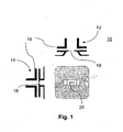
- the entire Doppler radar sensor is composed in this example of embodiment, of a waveguide transceiver and a planar circuit antenna 30.
- a planar transceiver could also be used the same way.
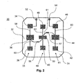
- the antenna of Fig. 2 is composed of three antenna elements or lines respectively of three patches each. Inside each line, the coupling is ensured by two (microstrip) lines 58, 60 connected on each side of the central patch 50 and feeding the edge patches 34, 36, 38, 40, 42, 44, 46, and 48.
- the length of each of these lines 58, 60 is designed so that the patches 34, 36, 38, 40, 42, 44, 46, and 48 are all radiating in phase along the line.
- the two lateral lines 58 and 60 are then linked to the central line 62 by horizontal coupling lines 61, 63, which have been designed to feed the lateral lines 58, 60 in phase and to save symmetry along the structure of the antenna 30.
- Some matching and relative power adjustment can be provided by the change of microstrip impedance resulting from the change in line width. This is useful to adjust the antenna horizontal radiation pattern and to optimize the return loss of the entire assembly.
- the power delivered to the central patch 50 is distributed to all the antenna elements 33, 41, 49 with the required proportion.
- PIN diodes 56 and 57 which are mounted on the horizontal coupling lines 63 and 61 respectively. These diodes 56 and 57 act as active switches with which the patches 34, 36, 38, and 42, 44, 46 can be connected with or disconnected from the central patch 50. This allows the control of the flow of microwave power to the lateral patches 34, 36, 38, and 42, 44, 46.
- the PIN-diodes 56 and 57 have the property to provide a low series resistance in "ON” state and a low capacitance in "OFF” state. Therefore, they are preferred elements in order to provide good switching performance without complicated matching circuitry around the PIN-diodes.
- the two lateral patch lines 33 and 41 are fed and the antenna behaves like a 3 x 3 patches antenna giving a narrow lobe in the horizontal plane. This configuration is used for narrow lobe applications.
- the antenna comprises a single line patch antenna with patches 40, 48, 50 and a wide radiation or reception pattern in the horizontal plane and a radiation or reception pattern similar to the pattern of a narrow lobe antenna in the vertical plane.
- the diodes 56 and 57 can be surface mount devices (SMD) having minimum package parasitic.
- SMD surface mount devices
- the diodes 56 and 57 can be mounted on the center of a matching pad where the microstrip width is larger. At this point, the level of impedance is rather low and the impedance of the diode in "OFF" state is sufficiently high to provide good isolation.
- Electromagnetic simulations have shown that a resonant patch antenna has a maximum voltage at the edges and a minimum on the center of the lateral side. This is precisely where a thin line is connected to provide the DC current to the diodes. Electromagnetic simulations have also shown that the rejection of Microwave power, using this strategy could reach up to 35 dB.
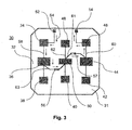
- Fig. 3 shows the DC-path of the antenna 30. DC-Current is applied by means of connection-pads 52 and 54, which are connected by thin lines to the patches 34 and 46 respectively.
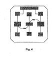
- Fig. 4 indicates the absorbing material applied to the surface of the antenna. The shape of the absorbing material is designed to stay on the antenna substrate.
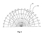
- Fig. 5 shows two possible lobes 70 and 72 generated by switching the configurations of the antenna.
- the lobes 70 and 72 relate to the horizontal distribution of the radiation patterns of the two configurations of the antenna. A mechanical change of the antenna is no longer required.
- a single antenna can simply provide different lobes by electronically switching.
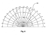
- the radiation pattern 80 is almost the same independently of the antenna configuration, as shown in Fig. 6 . Therefore, the vertical radiation pattern 80 is nearly identical for both configurations of the planar antenna 30.
- a foam radome can be used to protect the diodes.
- Electronic switching of the antenna opens the way to a control of the antenna by a processor and, by that mean, an adjustment of the radiation pattern by remote control. Not only it is possible to switch between the two extreme configurations, but also, through the use of an algorithm, it is possible to generate equivalent detection lobes being in between the two extremes. A weighting of the Doppler signal received in each configuration will be used to get all the intermediate states required.
- Fig. 7 shows a circuitry for IF Processing connected to a microwave transceiver 106.
- the planar antenna 30 is mounted on a transceiver 106.
- the processing obtains the Doppler signals of two diode mixers 100 and 102 provided in the microwave transceiver 106 for each of the two antenna configurations.
- a signal received by the antenna 30 is sampled in each configuration of the antenna 30 and a high speed switching is done between the two configurations of the antenna 30.
- Sample and hold circuits 114, 116, 118, and 120 are synchronized with the switching of the configurations of the antenna 30 in order to switch the output signals of the Sample and hold circuits 114, 116, 118, and 120 on the corresponding channels.
- the sampling clock can be provided either by the processor or by an auxiliary oscillator 108 whose frequency accuracy is not critical, provided it remains sufficiently high in order to provide good sampling.
- Pulse Width Modulation PWM
- PWM Pulse Width Modulation
- planar active antenna 30 used in an active antenna sensor delivers more information than a single antenna.
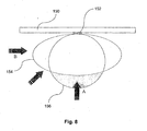
- the use of the extra information received from the planar active antenna 30 can lead to an effective pedestrian parallel traffic rejection algorithm used in door opener systems, as shown in Fig. 8 .
- Fig. 8 By observing simultaneously the amplitude of the Doppler signal coming from the two antenna configurations of an active antenna sensor 152 mounted on top of a door 150, it is possible to determine from which side a pedestrian is coming.
- the horizontal radiation patterns of the active antenna sensor 152 are carefully chosen one could then correlate the information generated by the same target in both antenna configurations in order to approximate the angle of the target trajectory compare to the axis of the sensor.
- the magnitude of the signals corresponding to the second configuration detection field 156 will be higher than the one corresponding to the first configuration detection field 154 (wide field).
- the magnitude of the signals corresponding to the wide detection field will be higher than the one corresponding to the narrow field.
Landscapes
- Engineering & Computer Science (AREA)
- Radar, Positioning & Navigation (AREA)
- Remote Sensing (AREA)
- Computer Networks & Wireless Communication (AREA)
- Physics & Mathematics (AREA)
- General Physics & Mathematics (AREA)
- Variable-Direction Aerials And Aerial Arrays (AREA)
- Waveguide Aerials (AREA)
- Radar Systems Or Details Thereof (AREA)
- Details Of Aerials (AREA)
Claims (9)
- Verfahren zum Detektieren von Bewegungen um eine automatische Tür herum unter Verwendung eines Doppler-Radarsensors, mit folgenden Schritten: Erzeugen eines Detektionsmusters und Detektieren des von einem sich bewegenden Ziel innerhalb des jeweiligen Detektionsmusters kommenden Dopplersignals, gekennzeichnet durch das Bereitstellen von mindestens zwei elektronisch auswählbaren Detektionsmustern; Auswählen der Detektionsmuster; Detektieren des von einem sich bewegenden Ziel innerhalb der jeweiligen Detektionsmuster kommenden Dopplersignals; und Verarbeiten des Dopplersignals in einer Schaltung zur Berechnung einer Bewegungsrichtung des sich bewegenden Ziels.
- Verfahren zum Detektieren von Bewegungen um eine automatische Tür herum nach Anspruch 1, gekennzeichnet durch das Durchführen eines Hochgeschwindigkeits-Umschaltens zwischen verschiedenen Detektionsmustern gemäß einem Algorithmus, wodurch sich eine dynamische Detektionskeule ergibt.
- Verfahren zum Detektieren von Bewegungen um eine automatische Tür herum nach Anspruch 1 oder 2, gekennzeichnet durch das Abtasten der für jedes Detektionsmuster jeweils erhaltenen Dopplersignale mit der Schaltung mit Abtast-Halte-Schaltungen (114, 116, 118, 120).
- Verfahren zum Detektieren von Bewegungen um eine automatische Tür herum nach Anspruch 1 oder 2, gekennzeichnet durch das Abtasten der für jedes Detektionsmuster jeweils erhaltenen Dopplersignale mit der Schaltung mit Abtast-Halte-Schaltungen (114, 116, 118, 120).
- Verfahren zum Detektieren von Bewegungen um eine automatische Tür herum nach einem der voran stehenden Ansprüche, gekennzeichnet durch das Verarbeiten des mindestens einen Doppler-Signals mit einer Schaltung mit digitalem Signalprozessor.
- Verfahren zum Detektieren von Bewegungen um eine automatische Tür herum nach einem der voran stehenden Ansprüche, gekennzeichnet durch das Berechnen, anhand der mindestens zwei verschiedenen Detektionsmustern entsprechenden Dopplersignale, eines Zwischenmusters zwischen den mindestens zwei Detektionsmustern durch Gewichtung ihrer jeweiligen Dopplersignale.
- Verfahren zum Detektieren von Bewegungen um eine automatische Tür herum nach einem der voran stehenden Ansprüche, gekennzeichnet durch Verwendung eines Dopplersignals von Detektionsfeldern mit breiter und schmaler Keule zur Erzeugung von Zwischenkeulen durch Softwaregewichtung der jeweiligen Signale.
- Verfahren zum Detektieren von Bewegungen um eine automatische Tür herum nach einem der Ansprüche 1 bis 5, gekennzeichnet durch das Ausführen eines Algorithmus, der die vom Doppler-Radarsensor empfangenen Daten derart verarbeitet, dass mindestens zwei verschiedene Detektionsmuster des Doppler-Radarsensors analysiert werden, um die Bewegungsrichtung eines Fußgängers zu berechnen, der sich im oder in der Nähe des vom Doppler-Radarsensor erfassten Bereich(s) bewegt, und anhand dieser Bewegungsrichtungsdaten, Erstellen einer Zurückweisung für parallel zur Ebene der Tür verlaufenden Verkehr.
- Verfahren zum Detektieren von Bewegungen um eine automatische Tür herum nach einem der voran stehenden Ansprüche, gekennzeichnet durch das Verwenden von gleichzeitigen Dopplersignalen von Detektionsfeldern mit breiter und schmaler Keule zur Anwendung eines Algorithmus, der diese verbesserte Qualität der Abtastinformation dazu verwendet, eine Zurückweisung für parallel zur Ebene der Tür verlaufenden Verkehr zu erstellen.
Priority Applications (1)
| Application Number | Priority Date | Filing Date | Title |
|---|---|---|---|
| DE60141366T DE60141366D1 (de) | 2001-10-19 | 2001-10-19 | Verfahren zur Detektierung von Bewegungen in der Nähe von automatischen Türen |
Applications Claiming Priority (1)
| Application Number | Priority Date | Filing Date | Title |
|---|---|---|---|
| EP01125007A EP1304764B1 (de) | 2001-10-19 | 2001-10-19 | Ebene Antenne |
Related Parent Applications (2)
| Application Number | Title | Priority Date | Filing Date |
|---|---|---|---|
| EP01125007A Division EP1304764B1 (de) | 2001-10-19 | 2001-10-19 | Ebene Antenne |
| EP01125007.3 Division | 2001-10-19 |
Publications (3)
| Publication Number | Publication Date |
|---|---|
| EP1832895A2 EP1832895A2 (de) | 2007-09-12 |
| EP1832895A3 EP1832895A3 (de) | 2008-07-23 |
| EP1832895B1 true EP1832895B1 (de) | 2010-02-17 |
Family
ID=8179024
Family Applications (2)
| Application Number | Title | Priority Date | Filing Date |
|---|---|---|---|
| EP01125007A Expired - Lifetime EP1304764B1 (de) | 2001-10-19 | 2001-10-19 | Ebene Antenne |
| EP07109302A Expired - Lifetime EP1832895B1 (de) | 2001-10-19 | 2001-10-19 | Verfahren zur Detektierung von Bewegungen in der Nähe von automatischen Türen |
Family Applications Before (1)
| Application Number | Title | Priority Date | Filing Date |
|---|---|---|---|
| EP01125007A Expired - Lifetime EP1304764B1 (de) | 2001-10-19 | 2001-10-19 | Ebene Antenne |
Country Status (8)
| Country | Link |
|---|---|
| US (2) | US6700542B2 (de) |
| EP (2) | EP1304764B1 (de) |
| JP (1) | JP4021740B2 (de) |
| KR (1) | KR20030032807A (de) |
| CN (1) | CN1251356C (de) |
| DE (2) | DE60141366D1 (de) |
| ES (2) | ES2341185T3 (de) |
| HK (1) | HK1057132A1 (de) |
Families Citing this family (56)
| Publication number | Priority date | Publication date | Assignee | Title |
|---|---|---|---|---|
| JP3664721B2 (ja) * | 2001-12-04 | 2005-06-29 | 松下電器産業株式会社 | アンテナおよび当該アンテナを備えた装置 |
| US6788258B2 (en) * | 2002-04-09 | 2004-09-07 | Arc Wireless Solutions, Inc. | Partially shared antenna aperture |
| KR100562785B1 (ko) * | 2002-11-25 | 2006-03-27 | 충남대학교산학협력단 | 프린트형 능동 야기-우다 안테나 |
| DE10328590A1 (de) * | 2003-06-25 | 2005-01-20 | Siemens Ag | Funkfernbedienung zur Abgabe von Befehlen an ein fernbedienbares Gerät |
| WO2005027267A1 (ja) * | 2003-09-09 | 2005-03-24 | National Institute Of Information And Communications Technology | 広帯域複数周波共用アンテナ |
| US7163155B2 (en) * | 2003-11-05 | 2007-01-16 | Interdigital Technology Corporation | ASIC-embedded switchable antenna arrays |
| US7187334B2 (en) * | 2004-10-29 | 2007-03-06 | Motorola, Inc. | Patch array feed for an automotive radar antenna |
| DE102004053821B4 (de) | 2004-11-04 | 2008-12-18 | Dorma Gmbh + Co. Kg | Türanlage mit automatisch verfahrbaren Flügeln sowie ein Verfahren zum Betrieb derartiger Türanlagen |
| EP1693544B1 (de) * | 2005-01-21 | 2016-03-23 | Bea S.A. | Sensor für automatischen Türen |
| EP1920496A1 (de) * | 2005-08-30 | 2008-05-14 | Telefonaktiebolaget LM Ericsson (PUBL) | Systeme und verfahren für eine umkonfigurierbare multimodus-sektorantenne |
| US8380132B2 (en) * | 2005-09-14 | 2013-02-19 | Delphi Technologies, Inc. | Self-structuring antenna with addressable switch controller |
| GB0604032D0 (en) * | 2006-02-28 | 2006-04-12 | E2V Tech Uk Ltd | Vehicle intruder alarm |
| US20070293178A1 (en) * | 2006-05-23 | 2007-12-20 | Darin Milton | Antenna Control |
| US7761115B2 (en) * | 2006-05-30 | 2010-07-20 | Broadcom Corporation | Multiple mode RF transceiver and antenna structure |
| CN101536051B (zh) * | 2006-09-28 | 2012-08-22 | B.E.A.有限公司 | 用于存在检测的传感器 |
| KR100842525B1 (ko) * | 2006-11-14 | 2008-07-01 | 삼성전자주식회사 | 휴대 단말기의 내장형 안테나 장치 |
| KR100842271B1 (ko) * | 2006-12-05 | 2008-06-30 | 한국전자통신연구원 | Rfid 리더용 선형 편파 다이버시티 안테나 장치 및 그제어 방법 |
| KR100842087B1 (ko) * | 2006-12-28 | 2008-06-30 | 삼성전자주식회사 | 어레이 안테나 시스템 |
| WO2008122073A1 (en) * | 2007-04-05 | 2008-10-16 | Keyless Technologies Pty Ltd | Portal access control system |
| US7508346B2 (en) * | 2007-04-16 | 2009-03-24 | Research In Motion Limited | Dual-polarized, microstrip patch antenna array, and associated methodology, for radio device |
| EP2040336B1 (de) * | 2007-08-03 | 2015-09-09 | InnoSenT GmbH | Radarsensor |
| WO2009052234A1 (en) | 2007-10-19 | 2009-04-23 | Board Of Trustees Of Michigan State University | Variable frequency patch antenna |
| DE102008008142B4 (de) | 2008-02-08 | 2019-01-17 | Agtatec Ag | Verfahren sowie Vorrichtung zur Ansteuerung und/oder Überwachung eines verfahrbaren Flügels, insbesondere einer Tür, eines Fensters oder dergleichen |
| DE102008008149B4 (de) | 2008-02-08 | 2022-01-05 | Agtatec Ag | Verfahren sowie Vorrichtung zur Ansteuerung und/oder Überwachung eines verfahrbaren Flügels, insbesondere einer Tür, eines Fensters oder dergleichen |
| US8340197B2 (en) * | 2008-02-28 | 2012-12-25 | Invertix Corporation | System and method for modulating a signal at an antenna |
| US8261491B2 (en) * | 2008-04-02 | 2012-09-11 | Leon Yulkowski | Concealed electrical door operator |
| DE102008023030B4 (de) | 2008-05-09 | 2016-11-17 | Innosent Gmbh | Radarantennenanordnung |
| WO2009144002A1 (de) | 2008-05-30 | 2009-12-03 | Bircher Reglomat Ag | Verfahren zum überwachen eines bewegungsbereichs |
| KR101044000B1 (ko) | 2008-11-13 | 2011-06-24 | 엘아이지넥스원 주식회사 | 도플러 주파수 측정방법과 장치 및 이를 이용한 레이더 세트의 시험 시스템 |
| US8391376B2 (en) * | 2008-11-25 | 2013-03-05 | Invertix Corporation | System and method for electronically steering an antenna |
| US8411794B2 (en) * | 2008-11-25 | 2013-04-02 | Invertix Corporation | System and method for arbitrary phase and amplitude modulation in an antenna |
| US8457251B2 (en) * | 2008-11-25 | 2013-06-04 | Invertix Corporation | System and method for spreading and de-spreading a signal at an antenna |
| US8653982B2 (en) | 2009-07-21 | 2014-02-18 | Openings | Door monitoring system |
| EP2309657A1 (de) * | 2009-10-08 | 2011-04-13 | Thomson Licensing | Verfahren zur Topologiekontrolle unter Verwendung von Sektorantennen in drahtlosen Netzen |
| US8750792B2 (en) | 2012-07-26 | 2014-06-10 | Remec Broadband Wireless, Llc | Transmitter for point-to-point radio system |
| CN105874648B (zh) * | 2014-06-30 | 2020-04-21 | 华为技术有限公司 | 具有径向波导的宽带灵活圆柱形天线阵列的装置和方法 |
| US9490535B2 (en) | 2014-06-30 | 2016-11-08 | Huawei Technologies Co., Ltd. | Apparatus and assembling method of a dual polarized agile cylindrical antenna array with reconfigurable radial waveguides |
| US9502765B2 (en) | 2014-06-30 | 2016-11-22 | Huawei Technologies Co., Ltd. | Apparatus and method of a dual polarized broadband agile cylindrical antenna array with reconfigurable radial waveguides |
| US10378262B2 (en) | 2014-10-23 | 2019-08-13 | Leon Yulkowski | Door operator and clutch |
| DE102014118036A1 (de) | 2014-12-05 | 2016-06-23 | Astyx Gmbh | Radarantenne und geeignetes Verfahren zum Beeinflussen der Abstrahlcharakteristik einer Radarantenne |
| CN104466433A (zh) * | 2014-12-08 | 2015-03-25 | 马瑞利汽车电子(广州)有限公司 | 一种车载射频接收天线装置 |
| DE202016100413U1 (de) | 2016-01-05 | 2017-04-07 | Hörmann KG Antriebstechnik | Annäherungstaster für eine automatische Tür oder ein automatisches Tor |
| US20170222330A1 (en) * | 2016-01-28 | 2017-08-03 | Royaltek Company Ltd. | Antenna device |
| EP3285334A1 (de) * | 2016-08-15 | 2018-02-21 | Nokia Solutions and Networks Oy | Strahlformungsantennengruppe |
| US10386460B2 (en) | 2017-05-15 | 2019-08-20 | Otis Elevator Company | Self-calibrating sensor for elevator and automatic door systems |
| US10221610B2 (en) | 2017-05-15 | 2019-03-05 | Otis Elevator Company | Depth sensor for automatic doors |
| GB2569620B (en) * | 2017-12-21 | 2021-12-29 | Canon Kk | Optimization of the performances of an antenna array |
| KR101943769B1 (ko) * | 2017-12-28 | 2019-04-17 | 광운대학교 산학협력단 | 배열 안테나 시스템 및 이를 이용한 빠른 전파 도달각 측정 방법 |
| DE102018100285B3 (de) | 2018-01-08 | 2019-04-25 | Hörmann KG Antriebstechnik | Taster-Vorrichtung und System mit einer Taster-Vorrichtung |
| DE102018202299A1 (de) * | 2018-02-15 | 2019-08-22 | Robert Bosch Gmbh | Antennenanordnung für einen Radarsensor |
| US10446930B1 (en) * | 2018-06-25 | 2019-10-15 | Nxp B.V. | Antenna combination device |
| CN109638437A (zh) * | 2018-12-07 | 2019-04-16 | 长沙瑞感电子科技有限公司 | 一种mimo毫米波微带阵列天线 |
| CN110581369A (zh) * | 2019-08-26 | 2019-12-17 | 维沃移动通信有限公司 | 一种天线模组及移动终端 |
| CN112201934B (zh) * | 2020-09-23 | 2021-10-08 | 华中科技大学 | 一种双频天线及天线阵列 |
| US12088013B2 (en) | 2021-03-30 | 2024-09-10 | Skyworks Solutions, Inc. | Frequency range two antenna array with switches for joining antennas for frequency range one communications |
| JP2023113002A (ja) | 2022-02-02 | 2023-08-15 | オプテックス株式会社 | 検出器、自動ドアシステムおよび開閉システム |
Family Cites Families (35)
| Publication number | Priority date | Publication date | Assignee | Title |
|---|---|---|---|---|
| JPS52132656A (en) * | 1976-04-28 | 1977-11-07 | Mitsubishi Electric Corp | Strip line type micro wave control circuit |
| JPS59189302U (ja) * | 1983-06-03 | 1984-12-15 | 株式会社東芝 | 導波管フイルタ回路 |
| JP2561648B2 (ja) * | 1985-01-25 | 1996-12-11 | 三菱電機株式会社 | アンテナ装置 |
| GB2211357A (en) * | 1987-09-23 | 1989-06-28 | Philips Electronic Associated | Integrated millimetre-wave transceiver |
| JP2568585B2 (ja) * | 1987-10-15 | 1997-01-08 | 松下電器産業株式会社 | 移動体検出装置 |
| GB9002636D0 (en) * | 1990-02-06 | 1990-04-04 | British Telecomm | Antenna |
| GB9026037D0 (en) | 1990-11-30 | 1991-01-16 | Marconi Gec Ltd | Motion detector unit |
| JPH04220094A (ja) * | 1990-12-19 | 1992-08-11 | Sony Corp | バースト位相検出回路 |
| JPH04299277A (ja) * | 1991-03-28 | 1992-10-22 | Mitsubishi Electric Corp | マイクロ波送受器 |
| US5315303A (en) | 1991-09-30 | 1994-05-24 | Trw Inc. | Compact, flexible and integrated millimeter wave radar sensor |
| JPH0581764U (ja) * | 1992-04-01 | 1993-11-05 | 三菱電機株式会社 | 車両検出装置 |
| DE59309609D1 (de) * | 1993-08-09 | 1999-07-01 | Siemens Ag | Dopplerradarmodul in Mikrostreifenleitungstechnik |
| US5512911A (en) * | 1994-05-09 | 1996-04-30 | Disys Corporation | Microwave integrated tuned detector |
| US5656980A (en) * | 1994-09-27 | 1997-08-12 | Harris Corporation | Multiple output RF filter and waveguide |
| JP3308734B2 (ja) * | 1994-10-13 | 2002-07-29 | 本田技研工業株式会社 | レーダーモジュール |
| JP3302848B2 (ja) | 1994-11-17 | 2002-07-15 | 本田技研工業株式会社 | 車載レーダー装置 |
| JP3511329B2 (ja) * | 1995-06-09 | 2004-03-29 | 本田技研工業株式会社 | 車載用レーダ装置 |
| DE19535962C1 (de) * | 1995-09-27 | 1997-02-13 | Siemens Ag | Dopplerradarmodul |
| US6061025A (en) * | 1995-12-07 | 2000-05-09 | Atlantic Aerospace Electronics Corporation | Tunable microstrip patch antenna and control system therefor |
| DE19547289C2 (de) | 1995-12-18 | 1998-02-12 | Siemens Ag | Frequenzmischer für ein Dopplerradarmodul |
| JPH09172323A (ja) * | 1995-12-20 | 1997-06-30 | Fujitsu General Ltd | 平面アンテナ |
| US5933109A (en) * | 1996-05-02 | 1999-08-03 | Honda Giken Kabushiki Kaisha | Multibeam radar system |
| JP3602258B2 (ja) * | 1996-05-02 | 2004-12-15 | 本田技研工業株式会社 | マルチビーム・レーダアンテナ |
| JPH1093322A (ja) * | 1996-09-18 | 1998-04-10 | Honda Motor Co Ltd | アンテナ装置 |
| US6064862A (en) * | 1997-07-18 | 2000-05-16 | Innova Corporation | Method and apparatus for external band selection of a digital microwave radio |
| JP3426934B2 (ja) * | 1997-10-09 | 2003-07-14 | 日本電信電話株式会社 | アンテナ装置 |
| US5966090A (en) * | 1998-03-16 | 1999-10-12 | Mcewan; Thomas E. | Differential pulse radar motion sensor |
| US6175723B1 (en) | 1998-08-12 | 2001-01-16 | Board Of Trustees Operating Michigan State University | Self-structuring antenna system with a switchable antenna array and an optimizing controller |
| US6020853A (en) * | 1998-10-28 | 2000-02-01 | Raytheon Company | Microstrip phase shifting reflect array antenna |
| JP2003509937A (ja) * | 1999-09-14 | 2003-03-11 | パラテック マイクロウェーブ インコーポレイテッド | 誘電体移相器を有する直列給電フェーズドアレイアンテナ |
| US6198438B1 (en) * | 1999-10-04 | 2001-03-06 | The United States Of America As Represented By The Secretary Of The Air Force | Reconfigurable microstrip antenna array geometry which utilizes micro-electro-mechanical system (MEMS) switches |
| JP4216979B2 (ja) * | 1999-12-24 | 2009-01-28 | 京セラ株式会社 | アンテナ給電線路およびそれを用いたアンテナモジュール |
| JP2001283347A (ja) * | 2000-03-28 | 2001-10-12 | Toto Ltd | 浴室人体検知装置 |
| WO2001092671A1 (de) * | 2000-05-31 | 2001-12-06 | Reglomat Ag | Anlage zur steuerung der position eines bewegbaren teiles |
| US6501427B1 (en) * | 2001-07-31 | 2002-12-31 | E-Tenna Corporation | Tunable patch antenna |
-
2001
- 2001-10-19 EP EP01125007A patent/EP1304764B1/de not_active Expired - Lifetime
- 2001-10-19 DE DE60141366T patent/DE60141366D1/de not_active Expired - Lifetime
- 2001-10-19 ES ES07109302T patent/ES2341185T3/es not_active Expired - Lifetime
- 2001-10-19 ES ES01125007T patent/ES2300296T3/es not_active Expired - Lifetime
- 2001-10-19 EP EP07109302A patent/EP1832895B1/de not_active Expired - Lifetime
- 2001-10-19 DE DE60133007T patent/DE60133007T2/de not_active Expired - Lifetime
-
2002
- 2002-04-10 CN CNB021058040A patent/CN1251356C/zh not_active Expired - Lifetime
- 2002-04-15 US US10/122,553 patent/US6700542B2/en not_active Expired - Lifetime
- 2002-05-17 KR KR1020020027387A patent/KR20030032807A/ko not_active Application Discontinuation
- 2002-10-15 JP JP2002301038A patent/JP4021740B2/ja not_active Expired - Fee Related
-
2003
- 2003-10-23 HK HK03107661A patent/HK1057132A1/xx not_active IP Right Cessation
-
2004
- 2004-01-28 US US10/767,829 patent/US7129892B2/en not_active Expired - Lifetime
Also Published As
| Publication number | Publication date |
|---|---|
| CN1412890A (zh) | 2003-04-23 |
| JP4021740B2 (ja) | 2007-12-12 |
| US7129892B2 (en) | 2006-10-31 |
| US6700542B2 (en) | 2004-03-02 |
| ES2341185T3 (es) | 2010-06-16 |
| DE60133007T2 (de) | 2009-03-19 |
| JP2003198247A (ja) | 2003-07-11 |
| ES2300296T3 (es) | 2008-06-16 |
| EP1304764A1 (de) | 2003-04-23 |
| DE60133007D1 (de) | 2008-04-10 |
| CN1251356C (zh) | 2006-04-12 |
| EP1304764B1 (de) | 2008-02-27 |
| DE60141366D1 (de) | 2010-04-01 |
| KR20030032807A (ko) | 2003-04-26 |
| HK1057132A1 (en) | 2004-03-12 |
| EP1832895A2 (de) | 2007-09-12 |
| EP1832895A3 (de) | 2008-07-23 |
| US20040185793A1 (en) | 2004-09-23 |
| US20030076271A1 (en) | 2003-04-24 |
Similar Documents
| Publication | Publication Date | Title |
|---|---|---|
| EP1832895B1 (de) | Verfahren zur Detektierung von Bewegungen in der Nähe von automatischen Türen | |
| EP0800093B1 (de) | Radarmodul und MMIC-Anordnung dafür | |
| US5815112A (en) | Planar array antenna and phase-comparison monopulse radar system | |
| US6215443B1 (en) | Radar module and antenna device | |
| EP0642190B1 (de) | Eingebaute Strahlerstruktur für einen Millimeterwellenradarsensor | |
| EP0867972B1 (de) | Aperturantenne und Radarsystem mit einer derartigen Antenne | |
| EP1438702B1 (de) | Fahrzeugverkehrssensor | |
| EP0693694B1 (de) | Doppler-Radarsystem für Kraftfahrzeuge | |
| EP1357395B1 (de) | Radarsensor | |
| JP3302848B2 (ja) | 車載レーダー装置 | |
| US11223112B2 (en) | Inverted microstrip travelling wave patch array antenna system | |
| US11515624B2 (en) | Integrated cavity backed slot array antenna system | |
| CN106953157B (zh) | 一种用于雷达传感器的天线装置 | |
| US6509874B1 (en) | Reactive matching for waveguide-slot-microstrip transitions | |
| US8390521B2 (en) | Antenna array for a radar transceiver and circuit configuration for supplying an antenna array of such a radar transceiver | |
| CN114006175A (zh) | 低旁瓣电平集成腔背槽阵列天线系统 |
Legal Events
| Date | Code | Title | Description |
|---|---|---|---|
| PUAI | Public reference made under article 153(3) epc to a published international application that has entered the european phase |
Free format text: ORIGINAL CODE: 0009012 |
|
| 17P | Request for examination filed |
Effective date: 20070606 |
|
| AC | Divisional application: reference to earlier application |
Ref document number: 1304764 Country of ref document: EP Kind code of ref document: P |
|
| AK | Designated contracting states |
Kind code of ref document: A2 Designated state(s): CH DE ES FR GB LI SE |
|
| PUAL | Search report despatched |
Free format text: ORIGINAL CODE: 0009013 |
|
| AK | Designated contracting states |
Kind code of ref document: A3 Designated state(s): CH DE ES FR GB LI SE |
|
| 17Q | First examination report despatched |
Effective date: 20081127 |
|
| AKX | Designation fees paid |
Designated state(s): CH DE ES FR GB LI SE |
|
| RTI1 | Title (correction) |
Free format text: METHOD OF DETECTING MOVEMENTS AROUND AUTOMATIC DOORS |
|
| GRAP | Despatch of communication of intention to grant a patent |
Free format text: ORIGINAL CODE: EPIDOSNIGR1 |
|
| GRAS | Grant fee paid |
Free format text: ORIGINAL CODE: EPIDOSNIGR3 |
|
| GRAA | (expected) grant |
Free format text: ORIGINAL CODE: 0009210 |
|
| AC | Divisional application: reference to earlier application |
Ref document number: 1304764 Country of ref document: EP Kind code of ref document: P |
|
| AK | Designated contracting states |
Kind code of ref document: B1 Designated state(s): CH DE ES FR GB LI SE |
|
| REG | Reference to a national code |
Ref country code: GB Ref legal event code: FG4D |
|
| REG | Reference to a national code |
Ref country code: CH Ref legal event code: EP |
|
| REF | Corresponds to: |
Ref document number: 60141366 Country of ref document: DE Date of ref document: 20100401 Kind code of ref document: P |
|
| REG | Reference to a national code |
Ref country code: SE Ref legal event code: TRGR |
|
| REG | Reference to a national code |
Ref country code: CH Ref legal event code: NV Representative=s name: AMMANN PATENTANWAELTE AG BERN |
|
| REG | Reference to a national code |
Ref country code: ES Ref legal event code: FG2A Ref document number: 2341185 Country of ref document: ES Kind code of ref document: T3 |
|
| PLBE | No opposition filed within time limit |
Free format text: ORIGINAL CODE: 0009261 |
|
| STAA | Information on the status of an ep patent application or granted ep patent |
Free format text: STATUS: NO OPPOSITION FILED WITHIN TIME LIMIT |
|
| 26N | No opposition filed |
Effective date: 20101118 |
|
| REG | Reference to a national code |
Ref country code: DE Ref legal event code: R008 Ref document number: 60141366 Country of ref document: DE |
|
| REG | Reference to a national code |
Ref country code: DE Ref legal event code: R039 Ref document number: 60141366 Country of ref document: DE Effective date: 20120217 |
|
| REG | Reference to a national code |
Ref country code: DE Ref legal event code: R097 Ref document number: 60141366 Country of ref document: DE |
|
| REG | Reference to a national code |
Ref country code: DE Ref legal event code: R040 Ref document number: 60141366 Country of ref document: DE Effective date: 20130809 |
|
| REG | Reference to a national code |
Ref country code: DE Ref legal event code: R082 Ref document number: 60141366 Country of ref document: DE Representative=s name: PUSCHMANN BORCHERT BARDEHLE PATENTANWAELTE PAR, DE |
|
| REG | Reference to a national code |
Ref country code: DE Ref legal event code: R082 Ref document number: 60141366 Country of ref document: DE Representative=s name: PUSCHMANN BORCHERT BARDEHLE PATENTANWAELTE PAR, DE Effective date: 20140326 Ref country code: DE Ref legal event code: R081 Ref document number: 60141366 Country of ref document: DE Owner name: BIRCHER REGLOMAT AG, CH Free format text: FORMER OWNER: BEA S.A., ANGLEUR, BE Effective date: 20140326 Ref country code: DE Ref legal event code: R081 Ref document number: 60141366 Country of ref document: DE Owner name: BEA S.A., BE Free format text: FORMER OWNER: BEA S.A., ANGLEUR, BE Effective date: 20140326 |
|
| REG | Reference to a national code |
Ref country code: FR Ref legal event code: PLFP Year of fee payment: 15 |
|
| REG | Reference to a national code |
Ref country code: FR Ref legal event code: PLFP Year of fee payment: 16 |
|
| REG | Reference to a national code |
Ref country code: FR Ref legal event code: PLFP Year of fee payment: 17 |
|
| REG | Reference to a national code |
Ref country code: FR Ref legal event code: PLFP Year of fee payment: 18 |
|
| PGFP | Annual fee paid to national office [announced via postgrant information from national office to epo] |
Ref country code: DE Payment date: 20201028 Year of fee payment: 20 Ref country code: ES Payment date: 20201117 Year of fee payment: 20 Ref country code: FR Payment date: 20201020 Year of fee payment: 20 Ref country code: GB Payment date: 20201023 Year of fee payment: 20 Ref country code: CH Payment date: 20201022 Year of fee payment: 20 Ref country code: SE Payment date: 20201022 Year of fee payment: 20 |
|
| REG | Reference to a national code |
Ref country code: DE Ref legal event code: R071 Ref document number: 60141366 Country of ref document: DE |
|
| REG | Reference to a national code |
Ref country code: CH Ref legal event code: PL |
|
| REG | Reference to a national code |
Ref country code: GB Ref legal event code: PE20 Expiry date: 20211018 |
|
| REG | Reference to a national code |
Ref country code: SE Ref legal event code: EUG |
|
| REG | Reference to a national code |
Ref country code: ES Ref legal event code: FD2A Effective date: 20220126 |
|
| PG25 | Lapsed in a contracting state [announced via postgrant information from national office to epo] |
Ref country code: GB Free format text: LAPSE BECAUSE OF EXPIRATION OF PROTECTION Effective date: 20211018 |
|
| PG25 | Lapsed in a contracting state [announced via postgrant information from national office to epo] |
Ref country code: ES Free format text: LAPSE BECAUSE OF EXPIRATION OF PROTECTION Effective date: 20211020 |