EP1832836B1 - Dart game device - Google Patents
Dart game device Download PDFInfo
- Publication number
- EP1832836B1 EP1832836B1 EP05822415.5A EP05822415A EP1832836B1 EP 1832836 B1 EP1832836 B1 EP 1832836B1 EP 05822415 A EP05822415 A EP 05822415A EP 1832836 B1 EP1832836 B1 EP 1832836B1
- Authority
- EP
- European Patent Office
- Prior art keywords
- dart
- light
- coordinate
- soft
- section
- Prior art date
- Legal status (The legal status is an assumption and is not a legal conclusion. Google has not performed a legal analysis and makes no representation as to the accuracy of the status listed.)
- Expired - Fee Related
Links
Images


Classifications
-
- F—MECHANICAL ENGINEERING; LIGHTING; HEATING; WEAPONS; BLASTING
- F41—WEAPONS
- F41J—TARGETS; TARGET RANGES; BULLET CATCHERS
- F41J3/00—Targets for arrows or darts, e.g. for sporting or amusement purposes
-
- F—MECHANICAL ENGINEERING; LIGHTING; HEATING; WEAPONS; BLASTING
- F41—WEAPONS
- F41J—TARGETS; TARGET RANGES; BULLET CATCHERS
- F41J3/00—Targets for arrows or darts, e.g. for sporting or amusement purposes
- F41J3/02—Indicators or score boards for arrow or dart games
-
- F—MECHANICAL ENGINEERING; LIGHTING; HEATING; WEAPONS; BLASTING
- F41—WEAPONS
- F41J—TARGETS; TARGET RANGES; BULLET CATCHERS
- F41J3/00—Targets for arrows or darts, e.g. for sporting or amusement purposes
- F41J3/0009—Dartboards
- F41J3/0033—Dartboards for use with safety darts
- F41J3/0042—Dartboards for use with safety darts having perforations for receiving blunt tip darts
-
- F—MECHANICAL ENGINEERING; LIGHTING; HEATING; WEAPONS; BLASTING
- F41—WEAPONS
- F41J—TARGETS; TARGET RANGES; BULLET CATCHERS
- F41J3/00—Targets for arrows or darts, e.g. for sporting or amusement purposes
- F41J3/0009—Dartboards
- F41J3/0061—Target faces
- F41J3/0071—Non-conventional target faces
-
- F—MECHANICAL ENGINEERING; LIGHTING; HEATING; WEAPONS; BLASTING
- F41—WEAPONS
- F41J—TARGETS; TARGET RANGES; BULLET CATCHERS
- F41J5/00—Target indicating systems; Target-hit or score detecting systems
- F41J5/02—Photo-electric hit-detector systems
Definitions
- the present invention relates to a dart game apparatus in which a player holds a soft dart and throws the soft dart at an image of a target displayed on a monitor.
- a dart board of an electronic dart game apparatus is composed of a disk-like target that is constituted by a bull's-eye located in the divided center, and a board which is provided with a plurality of holes in the form of a honeycomb surrounding the bull's-eye concentrically and circularly and which is sectioned into different scores.
- a shock thus obtained moves the target board backward, whereby an electrical contact is closed.
- a detection signal is sent to a control circuit, and thereby a predetermined score on the target board is displayed on a display board.
- an electrical contact section is returned elastically, and the target board into which the soft dart is inserted is pushed back, whereby the electrical contact is opened and the target board is returned to the original position thereof.
- each dart that projects on the backside of the target board sends a shock to the board sectioned into score units disposed within the target board.
- This board is equipped with an electrical contact, wherein the electrical contact is closed by the shock, whereby it is detected that the arrows are inserted into the board, and then detection signals are sent to a controller.
- the controller calculates the scores, which are displayed on a score display section (see, for example, Japanese Unexamined Patent Publication No. 2004-65973 (P.1, Fig. 6 ) and Japanese Examined Patent Publication No. S61-1680 (P.3, Fig. 4 )).
- a ball-throwing game equipment which is provided with: a plurality of optical sensors for detecting a position through which a thrown ball passes, the optical sensors being provided vertically and horizontally so as to face each other; and a control circuit for sending, on the basis of each signal sent from each optical sensor detecting the position, an image signal of a ball reaching position to a display screen that is a target of an image display device, wherein the size and pattern of the target displayed on the display screen are variably set by performing an input operation on the control circuit.
- This ball-throwing game equipment is configured such that a strikeout target is displayed on the display screen, the plurality of optical sensors for detecting the position through which the ball passes are provided face-to-face in vertical and horizontal directions in front of the screen, a controller for sending, on the basis of each signal sent from each optical sensor detecting the position, an image signal of a ball reaching position to the display screen that is a target of an image display device, and the size and pattern of the target displayed on the display screen are variably set by performing an input operation on the controller.
- This can be implemented as a dart game (see, for example, Japanese Unexamined Patent Publication No. 2003-159357 (P.1 through P.6; Fig. 4 )).
- scores can be acquired by means of a shock applied when a dart is inserted, the dart sometimes falls, or scores are obtained by means of a shock caused by things that cannot be inserted.
- scores do count as the number of dart throws but are not converted to real scores.
- he may misunderstand that scores are obtained and advance in the game, or he may misunderstand that he can throw a dart again and actually throw one.
- the design of the target can be changed by changing an image displayed on the display screen.
- the thrown balls hit the target and then fall, thus the next ball is thrown at the target on which there are no balls.
- the present invention is contrived in view of the above problems, and an object thereof is to obtain a dart board adopted in a game or a practice machine for competing throw control in which a soft dart or an arrow that is thrown first is inserted into a target and remains inserted on the target, whereby scores are calculated, wherein, when the dart falls after being inserted, the score for the thrown dart is not counted as a point, so that the game can be played according to the original rules of a dart game.
- Another object of the present invention is to obtain a dart board in which, even if a dart thrown at the dart board falls without being inserted, the throw can be recognized.
- a further object of the invention of the present application is to obtain a dart board in which the pattern or size of the dart board can be freely changed by using an image display body.
- Yet another object of the invention of the present application is to obtain a dart game apparatus in which a trouble of replacing/attaching a target can be eliminated by displaying the target on an image display device, and in which the size or pattern of the target is freely displayed on a display screen so that an interesting game or practice can be performed.
- Another object of the present invention is to obtain a dart game apparatus in which a moving image of the target is displayed so that a dart game having the moving image as the target can be played.
- a dart game apparatus has an image display device for displaying an image of a target; a panel body which is disposed on a front surface of a display screen of the image display device and through which the image displayed on the display screen of the image display device can be observed; and a coordinate position detecting device that detects a coordinate position of a soft dart abutting and held on the panel body.
- the dart game apparatus can have an image display body which displays an image of a target; a panel body, which has a plurality of holes each having a cross-sectional size substantially the same as that of an end of a soft dart, which is also formed, extending toward each hole, with an inclined surface in a ridge taken as a border between adjacent holes, and which is disposed in front of the image display body, and through which the image can be observed; and a coordinate detecting body which is disposed on a front surface of the panel body and detects coordinates of the position of the soft dart, the end of which is inserted into any of the plurality of holes, wherein the coordinate detecting body has at least four rims, in which so as to correspond to the four rims, two pairs of a light-emitting sensor section and a light-receiving sensor section for detecting light emitted by the light-emitting sensor section are provided respectively on the rims arranged face-to-face in parallel and, and the light-receiving sensor sections
- a second version of the dart game apparatus has: an image display body which displays an image of a target; a panel body, which has a plurality of holes each having a cross-sectional size substantially the same as that of an end of a soft dart, which is also formed, extending toward each hole, with an inclined surface in a ridge taken as a border between adjacent holes, and which is disposed in front of the image display body, and through which the image can be observed; and a first coordinate detecting body layer and a second coordinate detecting body layer, each of which has four rims, and in each of which, so as to correspond to the four rims, two pairs of a light-emitting sensor section and a light-receiving sensor section for detecting light emitted by the light-emitting sensor section are provided respectively on the rims arranged face-to-face in parallel, wherein the second coordinate detecting body layer is disposed at a predetermined displacement angle with respect to the first coordinate detecting body layer, the light-receiving sensor sections out
- a third version of the dart game apparatus has: an image display body which displays an image of a target; a panel body, which has a plurality of holes each having a cross-sectional size substantially the same as that of an end of a soft dart, which is also formed, extending toward each hole, with an inclined surface in a ridge taken as a border between adjacent holes, and which is disposed in front of the image display body, and through which the image can be observed; a coordinate detecting body which is disposed on a front surface of the panel body and detects coordinates of the position of the soft dart, the end of which is inserted into any of the plurality of holes; a target coordinate storage section that stores a position coordinate of the image of the target displayed on the image display body; a determination section which calculates a coordinate position of the position of the soft dart inserted into the panel body, by means of a detection signal sent from the coordinate detecting body, and determines whether the coordinate positionmatches the position coordinate stored in the target coordinate storage section; and a reporting
- a fourth version of the dart game apparatus has: an image display body which displays an image of a target; a panel body, which has a plurality of holes each having a cross-sectional size substantially the same as that of an end of a soft dart, which is also formed, extending toward each hole, with an inclined surface in a ridge taken as a border between adjacent holes, and which is disposed in front of the image display body, and through which the image can be observed; a first coordinate detecting body layer and a second coordinate detecting body layer, each of which has four rims, and in each of which, so as to correspond to the four rims, two pairs of a light-emitting sensor section and a light-receiving sensor section for detecting light emitted by the light-emitting sensor section are provided respectively on the rims arranged face-to-face in parallel, the second coordinate detecting body layer being disposed at a predetermined displacement angle with respect to the first coordinate detecting body layer, the dart game apparatus further having: a
- a fifth version of the dart game apparatus has: an image display body which displays an image of a target; a substantially transparent panel body in which a plurality of holes each having a cross-sectional size substantially the same as that of an end of a soft dart are adjacent to each other, and an inclined surface extending toward each hole is formed in a ridge taken as a border between adjacent holes, and which is provided in front of the image display body; a coordinate detecting body layer in which a plurality of optical sensors are provided face-to-face in a plurality of intersecting directions on rims surrounding the panel body in order to detect coordinates of the position of the soft dart, the end of which is inserted into a hole of the panel body, the coordinate detecting body layer being provided along a surface of the panel body that emits a detection signal sent from each sensor in each of the intersecting directions; an information storage section which stores image information and position information of the image displayed on the image display body; an image controller which reads the image information from the information storage section to generate an image generation signal, and displays
- a sixth version of the dart game apparatus has: an image display body which displays an image of a target; a panel body, which has a plurality of holes each having a cross-sectional size substantially the same as that of an end of a soft dart, which is also formed, extending toward each hole, with an inclined surface in a ridge taken as a border between adjacent holes, and which is disposed in front of the image display body, and through which the image can be observed; a first coordinate detecting body layer and a second coordinate detecting body layer, each of which has four rims, and in each of which, so as to correspond to the four rims, two pairs of a light-emitting sensor section and a light-receiving sensor section for detecting light emitted by the light-emitting sensor section are provided respectively on the rims arranged face-to-face in parallel and, the second coordinate detecting body layer being disposed at a predetermined displacement angle with respect to the first coordinate detecting body layer, the dart game apparatus further having: an information storage section
- a configuration is possible in which detection time for detecting the detection signal of each optical sensor of the coordinate detecting body is compared with predetermined reference time, and when the detection time is shorter, the determination section determines that the soft dart is not inserted into the dart board, and when the detection time is longer, the determination section determines that the soft dart is inserted into the dart board, and notifies the reporting section of the results of determination.
- a further version of the dart game apparatus has: an image display body which displays an image of a target; a panel body, which has a plurality of holes each having a cross-sectional size substantially the same as that of an end of a soft dart, which is also formed, extending toward each hole, with an inclined surface in a ridge taken as a border between adjacent holes, and which is disposed in front of the image display body, and through which the image can be observed; and a coordinate detecting body which is disposed on a front surface of the panel body and detects coordinates of the position of the soft dart, the end of which is inserted into any of the plurality of holes, wherein the coordinate detecting body has rims forming a hexagon where opposing rims are disposed parallel, in which , so as to correspond to the hexagon, three pairs of a light-emitting sensor section and a light-receiving sensor section for detecting light emitted by the light-emitting sensor section are provided respectively on the rims arranged face-to-
- the image of the target displayed by the image display body can be observed through the panel body disposed in front of the image display body.
- the soft dart is inserted into the panel body by throwing the soft dart at the target, and the soft dart inserted into the panel body can be securely detected by the optical sensors of the first coordinate detecting body layer and the second coordinate detecting body layer.
- the position of the inserted soft dart is calculated from the detection signal of the soft dart, determination is made based on the position information of the target that is stored in the target coordinate storage section as to what part of the target the soft dart is inserted, and the result of determination is reported by the reporting section.
- the soft darts inserted into the panel body can be securely detected for each hole by the optical sensors of the first coordinate detecting body layer and the second coordinate detecting body layer, thus the positions of the holes into which a plurality of darts are inserted can be securely specified.
- Fig. 1 is an external perspective view of the dart game apparatus according to the present invention.
- the front surface of a chassis 2 having a vertical rectangular solid form is provided with a dart game board 3 at substantially the eye level of a player in a standing position.
- the front surface of this chassis is provided with a coin slot, a mode selection switch and the like that are not shown, wherein the player inserts money into the coin slot, presses the mode selection switch to select a game mode, and plays a dart game.
- the player stands at a predetermined position in front of the chassis, and throws a soft dart at a target 4 displayed on the dart game board 3.
- the end of the soft dart 5 that reaches the dart game board 3 is inserted into the dart game board 3, the insertedposition on the image is detected, and scores are displayed in accordance with the inserted position.
- Fig. 1 the target 4 that is the same as the one used in a normal dart game is displayed on the dart game boar 3, but an arbitrary static image or video image of a moving image can be displayed according to the invention of the present application.
- Fig. 2 shows a side view of an example of the soft dart. All parts of the soft dart 5 are made from the same material except for a metallic dart part and the end of the soft dart 5, and the soft dart 5 is structured with safety measures so that it is not thrust into a person or a wall.
- the soft dart 5 has a soft tip 6 made of flexible resin at the end thereof, wherein the end is in the form of a short circular cone 6a, and a rear section of a small diameter section 6b having a diameter of 2 mm forms a circular truncated cone 6c, which flares into a skirt-like shape and is connected to a large diameter section 6d.
- the soft tip 6 is connected to a front end of a metallic barrel 7, a resin shaft 8 is connected to a rear section of the barrel 7, and a flight 9 is provided at a rear section of this shaft.
- the barrel 7 of the soft dart 5 is held in a hand, and the soft dart 5 is thrown, with the soft tip aiming at the target, whereby the soft dart 5 can be thrown straight.
- Fig. 3 is an exploded perspective view of the dart game board 3
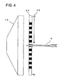
- Fig. 4 is a schematic sectional side view of the dart game board 3.
- an image display device 10 At the far side of the dart game board 3, there is disposed an image display device 10, a screen of which displays the target 4 shown in Fig. 1 or a target image 4a of a moving object.
- the image display device 10 can be realized by a television, plasma display, personal computer, liquid crystal display, monitor device, electronic display board, or the like. A game is played, standing in front of the image display device, thus a monitor device of a rear projector may be used.
- the size of an official dart board surface is 18 inches, thus the size of the image display device 10 is larger than 18 inches.
- a transparent panel body 20 into which the thrown soft dart 5 is inserted is attached parallel substantially closely to the screen in front of the image display device 10 so as to be parallel to the screen.
- a coordinate detecting device 30 that detects the position of the soft dart inserted into the panel.
- Fig. 5 is a block diagram of hardware of the dart game apparatus.
- a control circuit 40 is constituted by a controller 41, a memory section 42, and an operation input section 43.
- the controller 41 is constituted by a CPU 41a that controls the entire system, an image processor 41b that performs image processing on a displayed position of a video to be displayed on the screen or the size of the position, and a sound signal processor 41c that generates a sound.
- the memory section 42 is constituted by a ROM 42a that stores a program or data used in the controller 41, and a RAM 42b that temporarily stores various types of data obtained during a game.
- an operation panel 43a is connected to each of the control blocks 41, 42 via an interface 43b, the operation panel 43a being used to input various operation signals of a coin switch that detects money for playing a game, a select switch for selecting a game mode, and a start switch.
- the CPU 41a reads a game program in accordance with a boot program of the ROM 42a, causes the image processor 41b and the sound signal processor 41c to read and process image data and sound data stored in the ROM 42a, and outputs a video signal and a sound signal to the image display device 10 and an acoustic device 44 via interfaces 3a, 44a respectively.
- the target 4 is displayed on the screen of the image display device 10.
- the player inserts the money for playing game into the input section 43, selects a game mode by means of the select switch located on the operation panel 43a, and operates the start switch, whereby a dart game starts.
- the CPU 41a controls the progress of the game in accordance with the game program read from the ROM 42a, and uses a coin insertion signal sent from the operation input section 43 and an input signal sent from the select switch and the start switch, to conduct a game mode desired by the player.
- the player throws the soft dart at the target 4 from a predetermined distance away from the chassis, and the soft dart is inserted into the panel body 20 of the dart game board 3. In this manner, a game is played.
- the coordinate detecting device 30 detects the soft tip, and a detection signal obtained from this detection is sent to the controller. Then the CPU 41a compares the detection signal with coordinate information stored in the ROM to detect corresponding coordinates, whereby the position where the soft tip is inserted is specified.
- the score on the target which corresponds to the specified position, is read from a table stored in the ROM and counted as a point, and the image processor is caused to display a change in the video image of the target and the point on the image display device 10, while the sound signal processor is caused to generate a sound of a point being scored and to output the sound from a speaker.
- the control circuit 40 specifies the inserted position on the basis of the detection signal from the coordinate detecting device 30, and added points and the sound are outputted.
- the RAM 42b successively holds the position information of the target into which the soft tip is inserted, point information, the number of inserted soft darts, and the number of rounds, and the game is proceeded while outputting images and sounds based on these data items.
- the image processor 41b writes image data into the RAM 42b on the basis of a computation result of the program, and the written image data is sent to the image display device 10 via the interface (I/F) circuit 3a. Also, sound data outputted from the sound signal processor 41c is similarly sent to the acoustic device 44 via the interface (I/F) circuit 44a.
- Fig. 6 is a front view of the panel body 20.
- Fig. 6A is a front view of the panel body 20
- Fig. 6B is an enlarged view of a bordered square section in the panel body 20 shown in Fig. 6A .
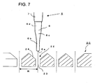
- Fig. 7 is a cross-sectional view of the panel body 20.
- the panel body 20 is a substantially transparent plate made of, for example, an acrylic material, and having the size substantially the same as that of the display screen of the image display device 10.
- the surface of the panel body 20 has diamond-like depressed areas 22 following the shape of a grid 21, and the center of each of the depressed areas 22 has a hole 23 into which the dart is inserted.
- the girds 21 are disposed vertically and horizontally at a regular interval of approximately 2.5 mm through 4 mm on the surface of the acrylic plate having a thickness of approximately 5 mm, and each of the grids 21 is provided with the diamond-like depressed area 22 in the form of an inverse quadrangular pyramid, on which a downward inclined surface 24 is formed at an angle of 30 through 45 degrees.
- the center of the depressed area 22 has the round hole 23 having a diameter of approximately 2 mm.
- the depressed area 22 is formed into a funnel in which the bottom part of the inverse quadrangular pyramid is provided with a cylinder.
- the hole 23 has a section size that is substantially the same as that of the soft tip 6 located at the end of the soft dart.
- the soft dart 5 thrown at the panel body 20 normally flies in a direction perpendicular to the surface of the panel body 20.
- the short circular cone 6a in the flexible soft tip of the soft dart 5 can hit anywhere on the surface of the panel body 20.
- the small diameter section 6b of the soft tip substantially corresponds to the diameter of the hole 23, thus the small diameter section 6b of the soft tip continues to move to the hole, whereby the circular truncated cone 6c of the soft tip abuts on the depressed area 22 and then stops.
- the surface of the panel body 20 is formed into a grid, wherein the inclined surfaces 24 are configured within the grid, and each of the holes 23 into which the soft tip 6 is inserted is opened in the center of the grid.
- the area of the surface of the panel body 20 is largely occupied the inclined surfaces 24, thus normally the end of the soft tip 6 hits the inclined surface 24 and slides on the inclined surface 24 in the direction of the hole 23, and is embedded in the hole 23 by being guided by the hole 23, whereby the soft dart 5 is inserted into and held on the panel body 20.
- the soft tip 6 is made of a flexible resin, and thus can be twisted by a shock when the dart 5 hits.
- the short circular cone 6a positioned at the end of the dart 5 collides with the inclined surface 24 the small diameter section 6b is twisted in a direction of inclination along the inclined surface, whereby the soft dart 5 is guided to the hole 23.
- the soft tip 6 collies with a ridge line of the grid 21.
- the ridge line that forms a ridge forming a rim line of the grid has the inclined surfaces 24 at both sides thereof at an angle of 90 through 120 degrees, and when the center of the short circular cone 6a of the soft tip hits either one of the inclined surfaces 24, the soft tip 6 is distorted in the direction of inclination, whereby the soft dart 5 is guided to the hole 23 positioned at the valley in the direction of inclination.
- the most of the soft dart thrown at the panel body 20 can be inserted into the hole 23 and held in the hole 23.
- Fig. 8 is a front schematic view of the coordinate detecting device 30.
- the coordinate detecting device 30 is positioned on the front surface side of the panel body 20, and the coordinate detecting device 30 plays a role of detecting the position of the soft dart 5 inserted into the panel body 20.
- the coordinate detecting device 30 has a rim body 31 having an appropriate thickness and formed into a rectangle having four rim side sections 31a, 31b, 31c and 31d that follow the rims of the display screen of the image display device 10 respectively.
- the rim body 31 has light-emitting sensor sections 32a, 32c, and light-receiving sensor sections 32b, 32d corresponding to the light-emitting sensor sections.
- the light-emitting sensor section 32a has a plurality of light-emitting elements 32a1 and 32a2 through 32an, while the light-receiving sensor section 32b has a plurality of light-receiving elements 32b1 and 32b2 through 32bn correspond to the light-emitting elements respectively.
- the light-emitting sensor section 32c has a plurality of light-emitting elements 32c1 and 32c2 through 32cn, while the light-receiving sensor section 32d has a plurality of light-receiving elements 32d1 and 32d2 through 32dn.
- the light-emitting elements 32a1, 32a2 through 32an, 32c1, 32c2 through 32cn it is preferred to use, in the embodiment, infrared-emitting diodes, in each of which a light-emitting axis has narrow directional characteristics.
- the light-receiving elements 32b1, 32b2 through 32bn, 32d1, and 32d2 through 32dn on the other hand, high-sensitive PIN photodiodes can be used.
- the installation intervals among the light-emitting elements 32a1, 32a2 through 32an, 32c1, 32c2 through 32cn, and among the light-receiving elements 32b1, 32b2 through 32bn, 32d1, and 32d2 through 32dn be a pitch width R between the holes of the panel body 20 (see Fig. 7 ).
- the light-emitting sensor sections 32a (light-emitting elements 32a1, 32a2 through 32an) and the light-emitting sensor sections 32c (32c1, 32c2 through 32cn) are controlled by the control circuit 40 and are, during a game, in a light-emitting state in which current is constantly applied.
- Each of the opposing light-receiving sensor sections 32b (light-receiving elements 32b1, 32b2 through 32bn) and 32d (light-receiving elements 32d1, 32d2 through 32dn) is constantly in a light-receiving state, and a light-reception signal from each of the light-receiving bodies 32b and 32d is sent to the control circuit 40.
- the soft dart 5 is inserted into any of the holes on the panel body 20, whereby the light axes that are emitted from the pair of the light-emitting sensor section 32a (light-emitting elements 32a1, 32a2 through 32an) and the light-emitting sensor section 32c (light-emitting elements 32c1, 32c2 through 32cn) passing through the hole in X and Y directions respectively are blocked.
- the corresponding light-receiving sensor section 32b (light-receiving elements 32b1, 32b2 through 32bn) and light-receiving sensor section 32d (light-receiving elements 32d1, 32d2 through 32dn) cannot receive the light, thus the light-reception signals are not sent to the control circuit 40.
- the control circuit 40 detects any of the elements of the light-receiving sensor section 32b (light-receiving elements 32b1, 32b2 through 32bn) and any of the elements of 32d (32d1, 32d2 through 32dn) by which the light is not received, whereby the position of X and Y coordinates of the soft dart 5 inserted in the panel body 20 can be specified.
- the game is executed in a way of competing for total points by throwing the soft dart 5 a number of times (three times).
- the configuration of the coordinate detecting device 30 shown in Fig. 8 there may arise a problem that, when the soft dart 5, which is thrown first, remains inserted in the panel body 20, the emitted light is blocked, whereby the coordinate position of the soft dart 5 that is subsequently thrown cannot be detected.
- the configuration shown in Fig. 8 is taken as a first detection layer 32, and a second detection layer 33 is further provided in this configuration, whereby the abovementioned problem can be resolved.
- the second detection layer 33 is provided with the pair of light-emitting sensor sections 34a, 34c, and the pair of light-receiving sensor sections 34b, 34d, and the first detection layer 32 is provided with the same in an oblique direction (with angle) .
- Fig. 9 shows the second detection layer 33 on the outside of the first detection layer 32 for the reason of explanation, actually the second detection layer 33 is provided in the same plane as the first detection layer 32 of the rim body 31, or on the front or far side of the first detection layer 32.
- the second detection layer 33 is positioned in the inclined rim body (referred to as "inclined rim body” hereinafter) in front of the first detection layer 32.
- the light-emitting sensor section 34a is disposed in an upper left rim section of the inclined rim body, and the light-receiving sensor section 34b corresponding to the light-emitting sensor section 34a is disposed in a lower right rim section of the inclined rim body.
- the light-emitting sensor section 34c is disposed in an upper right rim section of the inclined rim body, and the light-receiving sensor section 34d corresponding to the light-emitting sensor section 34c is disposed in a lower left rim section of the inclined rim body.
- the light-emitting sensor sections 34a and 34c have, respectively, a plurality of infrared-emitting diodes 35a1, 35a2 through 35an, and 35c1, 35c2 through 35cn, in each of which a light-emitting axis has the narrow directional characteristics.
- the light-receiving sensor sections 34b and 34d have, respectively, a plurality of high-sensitive PIN photodiodes 35b1, 35b2 through 35bn, and 35d1, 35d2 through 35dn, as the light-receiving elements.
- the installation intervals among the light-emitting elements and among the light-receiving elements be the pitch width R in which the light-axis of each light-emitting element passes through the hole 23 of the panel body 20, as described in Fig. 8 .
- Fig. 9 is used to explain a case in which the soft dart 5 is inserted into A, B and C of the panel body 20 in this order.
- the position of A can be detected by detection signals obtained from the pair of the light-emitting sensor section 32a and the light-receiving sensor section 32b, and the pair of the light-emitting sensor section 32c and the light-receiving sensor section 32d of the first detection layer 32.
- the X coordinate position on the first detection layer 32 overlaps with that of the A position, whereby the light emitted from the light-emitting sensor section 32c is blocked.
- the Y coordinate is different from that of the A position, the Y coordinate is detected by detecting light emission of the light-emitting sensor section 32a, whereby the B position can be specified.
- the X coordinate can be detected in the first detection layer 32, but whether the X coordinate overlaps with that of the A position or B position cannot be detected.
- the second detection layer 33 performs detection from the oblique direction by means of light emission of the light-emitting sensor sections 34a and 34c. Accordingly, all coordinate positions of the A position, B position and C position can be specified.
- the positions of the three soft darts can be specified no matter where these soft darts are inserted.
- the holes 23 on the panel body 20 are arranged orderly in vertical and horizontal directions at regular intervals in the form of a grid, and the optical sensors of the first detection layer 32 and the second detection layer 33 (the relationship between the light-emitting sensor section 32a and the light-receiving sensor section 32b, and the relationship between the light-emitting sensor section 32c and the light-receiving sensor section 32d) are disposed so as to intersect with each other at a position corresponding to a substantially center line of each hole 23 on the panel body 20.
- the reference time represents a basis for distinction between a case where the soft dart 5 bounces off the panel body 20 and falls, and a case where the soft dart 5 is securely inserted, and, for example, 0.5 seconds or 1 second is set as this reference time. If the reference time is set to a longer time period, a quick response cannot be obtained even if the soft dart is inserted securely, slowing response time.
- the CPU 41a of the controller 41 functions by means of the program processing.
- the detection time is shorter than the reference time, it is determined that the soft dart 5 is not inserted into the panel body 20.
- the detection time is longer, it is determined that the soft dart 5 is inserted into the panel body 20.
- a determination result is displayed on the image display device 10 as a change in the video, or displayed on a lamp or score display section provided in the chassis 2, and then reported to the player by outputting sound from the acoustic device 44.
- the soft dart 5 When it is determined that the soft dart 5 is not inserted into the panel body 20, the soft dart 5 is detected as one throw, the number of times that the soft dart 5 is thrown is counted sequentially, and thus obtained count values are stored in the memory section 42. The count values are displayed as an image on the image display device 10, or simultaneously reported to the player as a sound. When it is determined that the soft dart 5 is inserted into the panel body 20, the throw of the soft dart 5 is counted as one throw, the number of times that the soft dart 5 is thrown is stored as data into the memory section 42, and the data is reported to the player along with score information corresponding to the detection signal.
- the first detection layer 32 is configured such that the light-emitting sensor section 32a is provided in the vertical rim section 31a on the left-hand side of the light-emitting sensor section 32a and in the horizontal rim section 31c on the upper side, while the light-receiving sensor section 32b is provided in the vertical rim section 31b on the right-hand side of the light-receiving sensor section 32b and in the horizontal rim section 31d on the lower side.
- the light-emitting element and the light-receiving element may be configured face-to-face, thus the light-emitting sensor section 32a and the light-receiving sensor section 32b may be provided in either one of the vertical rim section 31a and the vertical rim section 31b, the vertical rim section 31a being positioned on the left-hand side of the light-emitting sensor section 32a and the vertical rim section 31b being positioned on the right-hand side of the light-receiving sensor section 32b.
- the light-emitting sensor section 32c and the light-receiving sensor section 32d may be provided in either one of the horizontal rim section 31c on the upper side and the horizontal rim section 31d on the lower side.
- the light-receiving sensor sections 32b and 32d each may be masked by a cut-on filter that allows the passage of only light with a wavelength of at least 6 through 7 ⁇ m in order to block the sunlight.
- the light-emitting sensor sections 32a and 32c may be configured to be able to emit light in the form of pulses.
- the second detection layer 33 may be configured such that the light-emitting sensors 34a, 34c and the light-receiving sensor sections 34b, 34d are disposed face-to-face.
- the first and second detection layers 22, 23 are provided so that three coordinate positions can be detected by means of the presence or absence of blockage of light emitted by the light-emitting sensor sections 32a, 32c, 34a, 34c (ON/OFF of the amount of light).
- the embodiment shown in Fig. 10 is configured so as to detect the coordinate positions by means of the changes in the amount of light received by the light-receiving elements. Accordingly, as compared with Fig. 9 , the three coordinate positions can be detected using only one detection layer.
- corresponding axes of the light-emitting sensor sections (light-emitting sides) and of the light-receiving sensor sections (light-receiving sides) are disposed in an inclined manner with respect to the panel body 20 in which the holes 23 into which the soft dart 5 is inserted are arranged in the form of a matrix in the X-axis direction and the Y-axis direction.
- a sensor recognizing range W is inclined with respect to the arrangement of the holes 23 of the panel body 20.
- Fig. 11A shows the amount of sensor light on the light-receiving side in the case in which none of the soft darts is inserted into the panel body 20, wherein the amount of light received LV in a detection range Z is 100%.
- Fig. 11B shows a state in which the soft dart is inserted into A or B shown in Fig. 10 .
- the amount of received light becomes lower than the amount of light received LV shown in Fig. 11A (e.g., the amount of received light becomes 2/3 of [LV]).
- Fig. 11C shows a state in which the soft darts are inserted into A and C' or B and C in Fig. 10 .
- the amount of received light is further reduced (e.g., the amount of received light becomes 2/3 of [LV]).
- Embodiment 1 in which the first light-receiving layer 22 is used, it is not possible to determine whether the third soft dart is inserted into the position of C or C' after soft darts are inserted into A and B.
- the third position can be determined by using the second light-receiving layer 23.
- Embodiment 4 shown in Fig. 10 the change in the amount of light are used so that the three coordinate positions can be detected by means of one light-receiving layer.
- Fig. 12 is a flow diagram of detection processing according to Embodiment 4.
- step S1 the light-receiving elements on the X and Y sides are scanned (step S1), the X and Y coordinate positions of the soft dart on the panel body 20 are specified by means of the change ( Fig. 11A to Fig. 11B ) in the amount of received light obtained by the soft dart inserted at one coordinate position (step S2).
- the detected coordinate positions are stored in the memory section 42, and a counter value is added (step S3).
- step S7 the three coordinates are determined by measuring the changes in the amount of received light, as described in Fig. 10 and Fig. 11 (step S7).
- the determined coordinates are stored in the memory section 42, a counter value is added thereto, and thus obtained result is used in appropriate program processing (step S8).
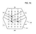
- Fig. 13 shows an embodiment in which the first detection layer 22 and the second detection layer 23 are integrated, unlike Embodiment 2 shown in Fig. 9 .
- a pair of the light-emitting sensor section and the light-receiving sensor section for detecting light emission of the light-emitting sensor section are provided on each one of three pairs of rims arranged parallel and face-to-face, so as to correspond to the hexagon (Aa-Ab, Ba-Bb, Ca-Cb).
- Two light-receiving sensor sections in the three pairs detect blockage of light emissions of the light-emitting sensor sections by not more than two soft darts inserted into the panel body, to detect the coordinates of the position of each of the two soft darts. Then, another one of the light-receiving sensor sections in the three pairs detects blockage of light emissions of the light-emitting sensor sections by the third soft dart inserted into the panel body, to detect the coordinates of the position of the third soft dart.
- the pair of the light-emitting sensor section Aa and the light-receiving sensor section Ab, the pair of the light-emitting sensor section Ba and the light-receiving sensor section Bb, and the pair of the light-emitting sensor section Ca and the light-receiving sensor section Cb are disposed in the form of a hexagon, each pair being disposed so as to face each other on the outer circumference of the plurality of holes 23 provided on the panel body 20. In this manner, one light-receiving layer is formed. Accordingly, as described in Fig. 9 , the coordinate positions can be detected from three directions, and determination can be made without causing the position of the third soft dart to overlap with the coordinates of each of the other soft darts.
- coordinate detecting device can be implemented by providing a reflection-type sensor on one of the opposing rim sections and attaching a mirror function that reflects the surface of the other rim section.
- the display device capable of displaying a moving image is used in order to display the target
- a wall paper having a picture of the target or an actual target plate may be disposed in place of the image display device.
- a translucent screen may be lit up from behind by using fluorescent light or the like so as to obtain good visual quality.
- each coordinate position on the panel body is allocated to the coordinates of each segment on the target in advance, and the allocated positions are stored in the memory section, whereby the position into which the soft dart is inserted can be detected by the coordinate detecting body.
- the coordinate detecting device 30 of the soft dart 5 is provided in front of the panel body 20.
- the coordinate detecting device 30 may be positioned between the image display device 10 and the panel body 20 as long as the soft tip of the soft dart 5 is designed to protrude out to the back of the panel body 20.
- the coordinate detecting device 30 having the configurations described in the present application monitors the detection signal by means of the light-receiving sensors, even when the soft dart 5 is slightly inserted into the panel body 20 configured as the target but falls without being completely inserted, thus an insertion failure can be detected. Moreover, even when the soft dart 5 hits the panel body 20 but falls without being inserted, such detection can be performed. In these cases, throws of the soft dart do not count as points, but one throw of the soft dart is detected, thus the game can be played according to the original rules of a dart game.
- the detection light beams of the optical sensors are disposed vertically, horizontally, and obliquely on the flat surface with respect to the panel body 20, thus the coordinate detecting device 30 can securely detect the positions of the three soft darts 5 thrown in one round of a dart game. Furthermore, even when the soft dart hits the panel body 20 but falls without being inserted into the panel body 20, the fact that the soft dart hit the dart board can be detected and the fact that the dart was thrown can be detected, thus determination can be made according to the original rules of the dart game.
- the pattern or size of the target can be changed by changing the display of the image display device 10, as a result of which coordinate detection can be performed, thus determination can be securely made as to whether the soft dart hits or not.
- the position of the target image displayed by the image display device 10 is moved by a software program, thus the target can be moved. Therefore, a non-conventional dart game can be enjoyed.
Description
- The present invention relates to a dart game apparatus in which a player holds a soft dart and throws the soft dart at an image of a target displayed on a monitor.
- A dart board of an electronic dart game apparatus is composed of a disk-like target that is constituted by a bull's-eye located in the divided center, and a board which is provided with a plurality of holes in the form of a honeycomb surrounding the bull's-eye concentrically and circularly and which is sectioned into different scores.
- A player throws a dart called "soft dart" at the target, the soft dart being in the form of a resin rod having a thin end. When the soft dart is inserted into one of the holes on a target board of each segment, a shock thus obtained moves the target board backward, whereby an electrical contact is closed. Accordingly, a detection signal is sent to a control circuit, and thereby a predetermined score on the target board is displayed on a display board. When the electrical contact is closed, an electrical contact section is returned elastically, and the target board into which the soft dart is inserted is pushed back, whereby the electrical contact is opened and the target board is returned to the original position thereof.
- When the next dart is thrown and inserted into any of the holes on the target board while keeping the soft dart inserted into the target board, the next score is detected.
- The end of each dart that projects on the backside of the target board sends a shock to the board sectioned into score units disposed within the target board. This board is equipped with an electrical contact, wherein the electrical contact is closed by the shock, whereby it is detected that the arrows are inserted into the board, and then detection signals are sent to a controller. The controller calculates the scores, which are displayed on a score display section (see, for example, Japanese Unexamined Patent Publication No.
2004-65973 Fig. 6 ) and Japanese Examined Patent Publication No.S61-1680 Fig. 4 )). - On the other hand, there is a ball-throwing game equipment which is provided with: a plurality of optical sensors for detecting a position through which a thrown ball passes, the optical sensors being provided vertically and horizontally so as to face each other; and a control circuit for sending, on the basis of each signal sent from each optical sensor detecting the position, an image signal of a ball reaching position to a display screen that is a target of an image display device, wherein the size and pattern of the target displayed on the display screen are variably set by performing an input operation on the control circuit.
- This ball-throwing game equipment is configured such that a strikeout target is displayed on the display screen, the plurality of optical sensors for detecting the position through which the ball passes are provided face-to-face in vertical and horizontal directions in front of the screen, a controller for sending, on the basis of each signal sent from each optical sensor detecting the position, an image signal of a ball reaching position to the display screen that is a target of an image display device, and the size and pattern of the target displayed on the display screen are variably set by performing an input operation on the controller. This can be implemented as a dart game (see, for example, Japanese Unexamined Patent Publication No.
2003-159357 Fig. 4 )). - Incidentally, in the technologies disclosed in Japanese Unexamined Patent Publication No.
2004-65973 Fig. 6 ) and Japanese Examined Patent Publication No. -
S61-1680 Fig. 4 ), the design of the target of each electronic dart game is fixed, and the design cannot be changed. Also, since the target is fixed, a dynamic target cannot be obtained. - Furthermore, in such target, although scores can be acquired by means of a shock applied when a dart is inserted, the dart sometimes falls, or scores are obtained by means of a shock caused by things that cannot be inserted. According to the rules of a dart game, such scores do count as the number of dart throws but are not converted to real scores. However, if one does not understand the rules of a dart game, he may misunderstand that scores are obtained and advance in the game, or he may misunderstand that he can throw a dart again and actually throw one.
- Moreover, in the technology described in Japanese Unexamined Patent Publication No.
2003-159357 Fig. 4 ), the design of the target can be changed by changing an image displayed on the display screen. However, after balls are thrown at the target one by one as with a strikeout, the thrown balls hit the target and then fall, thus the next ball is thrown at the target on which there are no balls. - In the case in which this technology is applied to a dart game, the following problems arise. Three darts are thrown in one round, wherein the dart that is thrown first remains inserted into the target. Therefore, the light from each optical sensor is blocked by the arrow that is thrown first, and, even when the next arrow is inserted into the area where the light is blocked, the optical sensor may not be activated. As a result, the position of a dart that is thrown subsequently cannot be detected.
-
US 5,054,792 (Danielson ) shows a darts game scoring system with an elaborate array of marker positions for different games. In some embodiments (Figure 7 ), an interchangeable transparent panel is placed in front of a panel region with marker positions. However, this arrangement is merely for scoring, for use with a conventional dartboard, and has the function of assisting the manual scoring process. - Therefore, the present invention is contrived in view of the above problems, and an object thereof is to obtain a dart board adopted in a game or a practice machine for competing throw control in which a soft dart or an arrow that is thrown first is inserted into a target and remains inserted on the target, whereby scores are calculated, wherein, when the dart falls after being inserted, the score for the thrown dart is not counted as a point, so that the game can be played according to the original rules of a dart game.
- Another object of the present invention is to obtain a dart board in which, even if a dart thrown at the dart board falls without being inserted, the throw can be recognized.
- A further object of the invention of the present application is to obtain a dart board in which the pattern or size of the dart board can be freely changed by using an image display body.
- Yet another object of the invention of the present application is to obtain a dart game apparatus in which a trouble of replacing/attaching a target can be eliminated by displaying the target on an image display device, and in which the size or pattern of the target is freely displayed on a display screen so that an interesting game or practice can be performed.
- Moreover, another object of the present invention is to obtain a dart game apparatus in which a moving image of the target is displayed so that a dart game having the moving image as the target can be played.
- The invention is defined in
claim 1. In embodiments, a dart game apparatus has an image display device for displaying an image of a target; a panel body which is disposed on a front surface of a display screen of the image display device and through which the image displayed on the display screen of the image display device can be observed; and a coordinate position detecting device that detects a coordinate position of a soft dart abutting and held on the panel body. - The dart game apparatus can have an image display body which displays an image of a target; a panel body, which has a plurality of holes each having a cross-sectional size substantially the same as that of an end of a soft dart, which is also formed, extending toward each hole, with an inclined surface in a ridge taken as a border between adjacent holes, and which is disposed in front of the image display body, and through which the image can be observed; and a coordinate detecting body which is disposed on a front surface of the panel body and detects coordinates of the position of the soft dart, the end of which is inserted into any of the plurality of holes, wherein the coordinate detecting body has at least four rims, in which so as to correspond to the four rims, two pairs of a light-emitting sensor section and a light-receiving sensor section for detecting light emitted by the light-emitting sensor section are provided respectively on the rims arranged face-to-face in parallel and, and the light-receiving sensor sections out of the two pairs detect blockage of light emissions of the light-emitting sensor sections by the soft dart inserted into the panel body, whereby the coordinates of the position of the soft dart are detected.
- A second version of the dart game apparatus has: an image display body which displays an image of a target; a panel body, which has a plurality of holes each having a cross-sectional size substantially the same as that of an end of a soft dart, which is also formed, extending toward each hole, with an inclined surface in a ridge taken as a border between adjacent holes, and which is disposed in front of the image display body, and through which the image can be observed; and a first coordinate detecting body layer and a second coordinate detecting body layer, each of which has four rims, and in each of which, so as to correspond to the four rims, two pairs of a light-emitting sensor section and a light-receiving sensor section for detecting light emitted by the light-emitting sensor section are provided respectively on the rims arranged face-to-face in parallel, wherein the second coordinate detecting body layer is disposed at a predetermined displacement angle with respect to the first coordinate detecting body layer, the light-receiving sensor sections out of the two pairs provided in the first coordinate detecting body layer detect blockage of light emissions of the light-emitting sensor sections by not more than two soft darts inserted into the panel body, whereby coordinates of the position of each of the two soft darts are detected, and the light-receiving sensor sections out of the two pairs provided in the second coordinate detecting body layer detect blockage of light emissions of the light-emitting sensor sections by a third soft dart inserted into the panel body, whereby coordinates of the position of the third soft dart are detected.
- Furthermore, a third version of the dart game apparatus has: an image display body which displays an image of a target; a panel body, which has a plurality of holes each having a cross-sectional size substantially the same as that of an end of a soft dart, which is also formed, extending toward each hole, with an inclined surface in a ridge taken as a border between adjacent holes, and which is disposed in front of the image display body, and through which the image can be observed; a coordinate detecting body which is disposed on a front surface of the panel body and detects coordinates of the position of the soft dart, the end of which is inserted into any of the plurality of holes; a target coordinate storage section that stores a position coordinate of the image of the target displayed on the image display body; a determination section which calculates a coordinate position of the position of the soft dart inserted into the panel body, by means of a detection signal sent from the coordinate detecting body, and determines whether the coordinate positionmatches the position coordinate stored in the target coordinate storage section; and a reporting section which reports a result of determination made by the determination section.
- Moreover, a fourth version of the dart game apparatus has: an image display body which displays an image of a target; a panel body, which has a plurality of holes each having a cross-sectional size substantially the same as that of an end of a soft dart, which is also formed, extending toward each hole, with an inclined surface in a ridge taken as a border between adjacent holes, and which is disposed in front of the image display body, and through which the image can be observed; a first coordinate detecting body layer and a second coordinate detecting body layer, each of which has four rims, and in each of which, so as to correspond to the four rims, two pairs of a light-emitting sensor section and a light-receiving sensor section for detecting light emitted by the light-emitting sensor section are provided respectively on the rims arranged face-to-face in parallel, the second coordinate detecting body layer being disposed at a predetermined displacement angle with respect to the first coordinate detecting body layer, the dart game apparatus further having: a target coordinate storage section which stores a position coordinate of the image of the target displayed on the image display body; a determination section which calculates a coordinate position of the position of the soft dart inserted into the panel body, by means of detection signals sent from the first and second coordinate detecting bodies, and determines whether the coordinate position matches the position coordinate stored in the target coordinate storage section; and a reporting section which reports a result of determination made by the determination section.
- A fifth version of the dart game apparatus has: an image display body which displays an image of a target; a substantially transparent panel body in which a plurality of holes each having a cross-sectional size substantially the same as that of an end of a soft dart are adjacent to each other, and an inclined surface extending toward each hole is formed in a ridge taken as a border between adjacent holes, and which is provided in front of the image display body; a coordinate detecting body layer in which a plurality of optical sensors are provided face-to-face in a plurality of intersecting directions on rims surrounding the panel body in order to detect coordinates of the position of the soft dart, the end of which is inserted into a hole of the panel body, the coordinate detecting body layer being provided along a surface of the panel body that emits a detection signal sent from each sensor in each of the intersecting directions; an information storage section which stores image information and position information of the image displayed on the image display body; an image controller which reads the image information from the information storage section to generate an image generation signal, and displays the image on the image display body; a coordinate position calculating section which calculates the position of the soft dart inserted into the panel body, by means of the detection signal from the coordinate detecting body layer; a determination section which uses coordinate information calculated by the coordinate position calculating section to determine whether the coordinates of the position of the soft dart match a position coordinate of the image of the target, the position coordinate being stored in the information storage section; and a reporting section which reports a result of determination made by the determination section.
- A sixth version of the dart game apparatus has: an image display body which displays an image of a target; a panel body, which has a plurality of holes each having a cross-sectional size substantially the same as that of an end of a soft dart, which is also formed, extending toward each hole, with an inclined surface in a ridge taken as a border between adjacent holes, and which is disposed in front of the image display body, and through which the image can be observed; a first coordinate detecting body layer and a second coordinate detecting body layer, each of which has four rims, and in each of which, so as to correspond to the four rims, two pairs of a light-emitting sensor section and a light-receiving sensor section for detecting light emitted by the light-emitting sensor section are provided respectively on the rims arranged face-to-face in parallel and, the second coordinate detecting body layer being disposed at a predetermined displacement angle with respect to the first coordinate detecting body layer, the dart game apparatus further having: an information storage section which stores image information and position information of the image displayed on the image display body; an image controller which reads the image information from the information storage section to generate an image generation signal, and displays the image on the image display body; a coordinate position calculating section which calculates the position of the soft dart inserted into the panel body, by means of detection signals from the first and second coordinate detecting bodies; a determination section which uses coordinate information calculated by the coordinate position calculating section to determine whether the coordinates of the position of the soft dart match a position coordinate of the image of the target, the position coordinate being stored in the information storage section; and a reporting section which reports a result of determination made by the determination section.
- In each of the above versions, a configuration is possible in which the holes on the panel body are arranged vertically and horizontally at regular intervals in the form of a grid, and optical axes of the optical sensors of the coordinate detecting body are disposed at intervals such that the optical axes intersect with each other at a position corresponding to a substantially center line of each hole in the panel body.
- Also, in each of the above versions, a configuration is possible in which detection time for detecting the detection signal of each optical sensor of the coordinate detecting body is compared with predetermined reference time, and when the detection time is shorter, the determination section determines that the soft dart is not inserted into the dart board, and when the detection time is longer, the determination section determines that the soft dart is inserted into the dart board, and notifies the reporting section of the results of determination.
- In each of the above versions, a configuration is possible in which when determination is made that the soft dart is not inserted into the dart board, the soft dart is counted as one throw, which is then reported to the reporting section, and when determination is made that the soft dart is inserted into the dart board, the soft dart is counted as one throw, which is then reported to the reporting section along with score information corresponding to the detection signal.
- A further version of the dart game apparatus has: an image display body which displays an image of a target; a panel body, which has a plurality of holes each having a cross-sectional size substantially the same as that of an end of a soft dart, which is also formed, extending toward each hole, with an inclined surface in a ridge taken as a border between adjacent holes, and which is disposed in front of the image display body, and through which the image can be observed; and a coordinate detecting body which is disposed on a front surface of the panel body and detects coordinates of the position of the soft dart, the end of which is inserted into any of the plurality of holes, wherein the coordinate detecting body has rims forming a hexagon where opposing rims are disposed parallel, in which , so as to correspond to the hexagon, three pairs of a light-emitting sensor section and a light-receiving sensor section for detecting light emitted by the light-emitting sensor section are provided respectively on the rims arranged face-to-face in parallel, two pairs of the light-receiving sensor sections out of the three pairs detect blockage of light emissions of the light-emitting sensor sections by not more than two soft darts inserted into the panel body, whereby coordinates of the position of each of the two soft darts are detected, and another pair of the light-receiving sensor sections out of the three pairs detects blockage of light emissions of the light-emitting sensor sections by a third soft dart inserted into the panel body, whereby coordinates of the position of the third soft dart are detected. According to the above configuration, the image of the target displayed by the image display body can be observed through the panel body disposed in front of the image display body. The soft dart is inserted into the panel body by throwing the soft dart at the target, and the soft dart inserted into the panel body can be securely detected by the optical sensors of the first coordinate detecting body layer and the second coordinate detecting body layer. Moreover, the position of the inserted soft dart is calculated from the detection signal of the soft dart, determination is made based on the position information of the target that is stored in the target coordinate storage section as to what part of the target the soft dart is inserted, and the result of determination is reported by the reporting section.
- Also, the soft darts inserted into the panel body can be securely detected for each hole by the optical sensors of the first coordinate detecting body layer and the second coordinate detecting body layer, thus the positions of the holes into which a plurality of darts are inserted can be securely specified.
-
-
Fig. 1 is an external perspective view of a dart game apparatus; -
Fig. 2 is a side view of a soft dart; -
Fig. 3 is an exploded perspective view of a dart game board; -
Fig. 4 is a side view of the dart game board; -
Fig. 5 is a block diagram of hardware of the dart game apparatus; -
Fig. 6 is a front view of a panel body; -
Fig. 7 is a cross-sectional view of a panel; -
Fig. 8 is a front schematic view of a coordinate detecting device; -
Fig. 9 is an explanatory diagram in which a second detection layer is added to a first detection layer shown inFig. 8 ; -
Fig. 10 is a figure showing a configuration example in which a coordinate position is detected by means of a change in the amount of light received by a light-receiving element; -
Fig. 11 is a figure for explaining operation of the embodiment ofFig. 10 ; -
Fig. 12 is a flow diagram of detection processing according toEmbodiment 4; and -
Fig. 13 is an embodiment in which afirst detection layer 22 and asecond detection layer 23 are integrated, unlikeEmbodiment 2 shown inFig. 9 . - Hereinafter, embodiments of the dart board and the dart game apparatus using this dart board according to the present invention are described in detail with reference to the embodiments shown in the drawings.
- The best embodiments of the present invention are described with reference to the drawings.
Fig. 1 is an external perspective view of the dart game apparatus according to the present invention. In thedart game apparatus 1, the front surface of achassis 2 having a vertical rectangular solid form is provided with adart game board 3 at substantially the eye level of a player in a standing position. The front surface of this chassis is provided with a coin slot, a mode selection switch and the like that are not shown, wherein the player inserts money into the coin slot, presses the mode selection switch to select a game mode, and plays a dart game. - The player stands at a predetermined position in front of the chassis, and throws a soft dart at a
target 4 displayed on thedart game board 3. The end of thesoft dart 5 that reaches thedart game board 3 is inserted into thedart game board 3, the insertedposition on the image is detected, and scores are displayed in accordance with the inserted position. - In
Fig. 1 , thetarget 4 that is the same as the one used in a normal dart game is displayed on thedart game boar 3, but an arbitrary static image or video image of a moving image can be displayed according to the invention of the present application. -
Fig. 2 shows a side view of an example of the soft dart. All parts of thesoft dart 5 are made from the same material except for a metallic dart part and the end of thesoft dart 5, and thesoft dart 5 is structured with safety measures so that it is not thrust into a person or a wall. Thesoft dart 5 has asoft tip 6 made of flexible resin at the end thereof, wherein the end is in the form of a short circular cone 6a, and a rear section of a small diameter section 6b having a diameter of 2 mm forms a circular truncated cone 6c, which flares into a skirt-like shape and is connected to a large diameter section 6d. - The
soft tip 6 is connected to a front end of ametallic barrel 7, aresin shaft 8 is connected to a rear section of thebarrel 7, and aflight 9 is provided at a rear section of this shaft. Thebarrel 7 of thesoft dart 5 is held in a hand, and thesoft dart 5 is thrown, with the soft tip aiming at the target, whereby thesoft dart 5 can be thrown straight. -
Fig. 3 is an exploded perspective view of thedart game board 3, andFig. 4 is a schematic sectional side view of thedart game board 3. At the far side of thedart game board 3, there is disposed animage display device 10, a screen of which displays thetarget 4 shown inFig. 1 or a target image 4a of a moving object. - The
image display device 10 can be realized by a television, plasma display, personal computer, liquid crystal display, monitor device, electronic display board, or the like. A game is played, standing in front of the image display device, thus a monitor device of a rear projector may be used. - When assuming that the
image display device 10 is large enough to contain a normal dart board surface, the size of an official dart board surface is 18 inches, thus the size of theimage display device 10 is larger than 18 inches. - A
transparent panel body 20 into which the thrownsoft dart 5 is inserted is attached parallel substantially closely to the screen in front of theimage display device 10 so as to be parallel to the screen. In front of thepanel body 20, there is provided a coordinate detectingdevice 30 that detects the position of the soft dart inserted into the panel. -
Fig. 5 is a block diagram of hardware of the dart game apparatus. Acontrol circuit 40 is constituted by acontroller 41, a memory section 42, and an operation input section 43. Thecontroller 41 is constituted by a CPU 41a that controls the entire system, an image processor 41b that performs image processing on a displayed position of a video to be displayed on the screen or the size of the position, and a sound signal processor 41c that generates a sound. The memory section 42 is constituted by a ROM 42a that stores a program or data used in thecontroller 41, and a RAM 42b that temporarily stores various types of data obtained during a game. Furthermore, in the operation input section 43, an operation panel 43a is connected to each of the control blocks 41, 42 via an interface 43b, the operation panel 43a being used to input various operation signals of a coin switch that detects money for playing a game, a select switch for selecting a game mode, and a start switch. - Once the power is turned on, the CPU 41a reads a game program in accordance with a boot program of the ROM 42a, causes the image processor 41b and the sound signal processor 41c to read and process image data and sound data stored in the ROM 42a, and outputs a video signal and a sound signal to the
image display device 10 and anacoustic device 44 via interfaces 3a, 44a respectively. - The
target 4 is displayed on the screen of theimage display device 10. The player inserts the money for playing game into the input section 43, selects a game mode by means of the select switch located on the operation panel 43a, and operates the start switch, whereby a dart game starts. - The CPU 41a controls the progress of the game in accordance with the game program read from the ROM 42a, and uses a coin insertion signal sent from the operation input section 43 and an input signal sent from the select switch and the start switch, to conduct a game mode desired by the player.
- The player throws the soft dart at the
target 4 from a predetermined distance away from the chassis, and the soft dart is inserted into thepanel body 20 of thedart game board 3. In this manner, a game is played. When thesoft tip 6, which the player throws at thetarget 4 displayed on theimage display device 10 of the game board, is inserted into thepanel body 20, the coordinate detectingdevice 30 detects the soft tip, and a detection signal obtained from this detection is sent to the controller. Then the CPU 41a compares the detection signal with coordinate information stored in the ROM to detect corresponding coordinates, whereby the position where the soft tip is inserted is specified. - The score on the target, which corresponds to the specified position, is read from a table stored in the ROM and counted as a point, and the image processor is caused to display a change in the video image of the target and the point on the
image display device 10, while the sound signal processor is caused to generate a sound of a point being scored and to output the sound from a speaker. Accordingly, thecontrol circuit 40 specifies the inserted position on the basis of the detection signal from the coordinate detectingdevice 30, and added points and the sound are outputted. - The RAM 42b successively holds the position information of the target into which the soft tip is inserted, point information, the number of inserted soft darts, and the number of rounds, and the game is proceeded while outputting images and sounds based on these data items. The image processor 41b writes image data into the RAM 42b on the basis of a computation result of the program, and the written image data is sent to the
image display device 10 via the interface (I/F) circuit 3a. Also, sound data outputted from the sound signal processor 41c is similarly sent to theacoustic device 44 via the interface (I/F) circuit 44a. -
Fig. 6 is a front view of thepanel body 20.Fig. 6A is a front view of thepanel body 20, andFig. 6B is an enlarged view of a bordered square section in thepanel body 20 shown inFig. 6A .Fig. 7 is a cross-sectional view of thepanel body 20. Thepanel body 20 is a substantially transparent plate made of, for example, an acrylic material, and having the size substantially the same as that of the display screen of theimage display device 10. The surface of thepanel body 20 has diamond-likedepressed areas 22 following the shape of agrid 21, and the center of each of thedepressed areas 22 has ahole 23 into which the dart is inserted. - On the
panel body 20, thegirds 21 are disposed vertically and horizontally at a regular interval of approximately 2.5 mm through 4 mm on the surface of the acrylic plate having a thickness of approximately 5 mm, and each of thegrids 21 is provided with the diamond-likedepressed area 22 in the form of an inverse quadrangular pyramid, on which a downwardinclined surface 24 is formed at an angle of 30 through 45 degrees. The center of thedepressed area 22 has theround hole 23 having a diameter of approximately 2 mm. Thedepressed area 22 is formed into a funnel in which the bottom part of the inverse quadrangular pyramid is provided with a cylinder. - By this structure, the
soft dart 5 coming to thepanel body 20 is inserted into thehole 23. Thehole 23 has a section size that is substantially the same as that of thesoft tip 6 located at the end of the soft dart. - The
soft dart 5 thrown at thepanel body 20 normally flies in a direction perpendicular to the surface of thepanel body 20. The short circular cone 6a in the flexible soft tip of thesoft dart 5 can hit anywhere on the surface of thepanel body 20. In the case in which thesoft tip 6 is inserted directly into thehole 23, the small diameter section 6b of the soft tip substantially corresponds to the diameter of thehole 23, thus the small diameter section 6b of the soft tip continues to move to the hole, whereby the circular truncated cone 6c of the soft tip abuts on thedepressed area 22 and then stops. - The surface of the
panel body 20 is formed into a grid, wherein theinclined surfaces 24 are configured within the grid, and each of theholes 23 into which thesoft tip 6 is inserted is opened in the center of the grid. The area of the surface of thepanel body 20 is largely occupied theinclined surfaces 24, thus normally the end of thesoft tip 6 hits theinclined surface 24 and slides on theinclined surface 24 in the direction of thehole 23, and is embedded in thehole 23 by being guided by thehole 23, whereby thesoft dart 5 is inserted into and held on thepanel body 20. - The
soft tip 6 is made of a flexible resin, and thus can be twisted by a shock when thedart 5 hits. When the short circular cone 6a positioned at the end of thedart 5 collides with theinclined surface 24, the small diameter section 6b is twisted in a direction of inclination along the inclined surface, whereby thesoft dart 5 is guided to thehole 23. - Furthermore, the
soft tip 6 collies with a ridge line of thegrid 21. The ridge line that forms a ridge forming a rim line of the grid has theinclined surfaces 24 at both sides thereof at an angle of 90 through 120 degrees, and when the center of the short circular cone 6a of the soft tip hits either one of theinclined surfaces 24, thesoft tip 6 is distorted in the direction of inclination, whereby thesoft dart 5 is guided to thehole 23 positioned at the valley in the direction of inclination. - In this manner, the most of the soft dart thrown at the
panel body 20 can be inserted into thehole 23 and held in thehole 23. -
Fig. 8 is a front schematic view of the coordinate detectingdevice 30. The coordinate detectingdevice 30 is positioned on the front surface side of thepanel body 20, and the coordinate detectingdevice 30 plays a role of detecting the position of thesoft dart 5 inserted into thepanel body 20. - The coordinate detecting
device 30 has arim body 31 having an appropriate thickness and formed into a rectangle having four rim side sections 31a, 31b, 31c and 31d that follow the rims of the display screen of theimage display device 10 respectively. Therim body 31 has light-emitting sensor sections 32a, 32c, and light-receiving sensor sections 32b, 32d corresponding to the light-emitting sensor sections. - The light-emitting sensor section 32a has a plurality of light-emitting elements 32a1 and 32a2 through 32an, while the light-receiving sensor section 32b has a plurality of light-receiving elements 32b1 and 32b2 through 32bn correspond to the light-emitting elements respectively.
- The light-emitting sensor section 32c has a plurality of light-emitting elements 32c1 and 32c2 through 32cn, while the light-receiving sensor section 32d has a plurality of light-receiving elements 32d1 and 32d2 through 32dn.
- As the light-emitting elements 32a1, 32a2 through 32an, 32c1, 32c2 through 32cn, it is preferred to use, in the embodiment, infrared-emitting diodes, in each of which a light-emitting axis has narrow directional characteristics. As the light-receiving elements 32b1, 32b2 through 32bn, 32d1, and 32d2 through 32dn, on the other hand, high-sensitive PIN photodiodes can be used.
- It is preferred that the installation intervals among the light-emitting elements 32a1, 32a2 through 32an, 32c1, 32c2 through 32cn, and among the light-receiving elements 32b1, 32b2 through 32bn, 32d1, and 32d2 through 32dn be a pitch width R between the holes of the panel body 20 (see
Fig. 7 ). - The light-emitting sensor sections 32a (light-emitting elements 32a1, 32a2 through 32an) and the light-emitting sensor sections 32c (32c1, 32c2 through 32cn) are controlled by the
control circuit 40 and are, during a game, in a light-emitting state in which current is constantly applied. Each of the opposing light-receiving sensor sections 32b (light-receiving elements 32b1, 32b2 through 32bn) and 32d (light-receiving elements 32d1, 32d2 through 32dn) is constantly in a light-receiving state, and a light-reception signal from each of the light-receiving bodies 32b and 32d is sent to thecontrol circuit 40. Accordingly, thesoft dart 5 is inserted into any of the holes on thepanel body 20, whereby the light axes that are emitted from the pair of the light-emitting sensor section 32a (light-emitting elements 32a1, 32a2 through 32an) and the light-emitting sensor section 32c (light-emitting elements 32c1, 32c2 through 32cn) passing through the hole in X and Y directions respectively are blocked. Accordingly, the corresponding light-receiving sensor section 32b (light-receiving elements 32b1, 32b2 through 32bn) and light-receiving sensor section 32d (light-receiving elements 32d1, 32d2 through 32dn) cannot receive the light, thus the light-reception signals are not sent to thecontrol circuit 40. Thecontrol circuit 40 detects any of the elements of the light-receiving sensor section 32b (light-receiving elements 32b1, 32b2 through 32bn) and any of the elements of 32d (32d1, 32d2 through 32dn) by which the light is not received, whereby the position of X and Y coordinates of thesoft dart 5 inserted in thepanel body 20 can be specified. - Here, in the case in which the
target 4 shown inFig. 1 is displayed to play a normal dart game, the game is executed in a way of competing for total points by throwing the soft dart 5 a number of times (three times). In this case, in the configuration of the coordinate detectingdevice 30 shown inFig. 8 , there may arise a problem that, when thesoft dart 5, which is thrown first, remains inserted in thepanel body 20, the emitted light is blocked, whereby the coordinate position of thesoft dart 5 that is subsequently thrown cannot be detected. - Therefore, in the second embodiment, the configuration shown in
Fig. 8 is taken as afirst detection layer 32, and asecond detection layer 33 is further provided in this configuration, whereby the abovementioned problem can be resolved. - Specifically, as shown in
Fig. 9 , thesecond detection layer 33 is provided with the pair of light-emitting sensor sections 34a, 34c, and the pair of light-receiving sensor sections 34b, 34d, and thefirst detection layer 32 is provided with the same in an oblique direction (with angle) . AlthoughFig. 9 shows thesecond detection layer 33 on the outside of thefirst detection layer 32 for the reason of explanation, actually thesecond detection layer 33 is provided in the same plane as thefirst detection layer 32 of therim body 31, or on the front or far side of thefirst detection layer 32. - Here, for the reason of explanation, the
second detection layer 33 is positioned in the inclined rim body (referred to as "inclined rim body" hereinafter) in front of thefirst detection layer 32. - In the
second detection layer 33, the light-emitting sensor section 34a is disposed in an upper left rim section of the inclined rim body, and the light-receiving sensor section 34b corresponding to the light-emitting sensor section 34a is disposed in a lower right rim section of the inclined rim body. - Similarly, the light-emitting sensor section 34c is disposed in an upper right rim section of the inclined rim body, and the light-receiving sensor section 34d corresponding to the light-emitting sensor section 34c is disposed in a lower left rim section of the inclined rim body.
- As in the
first detection layer 32 described inFig. 8 , the light-emitting sensor sections 34a and 34c have, respectively, a plurality of infrared-emitting diodes 35a1, 35a2 through 35an, and 35c1, 35c2 through 35cn, in each of which a light-emitting axis has the narrow directional characteristics. - On the other hand, the light-receiving sensor sections 34b and 34d have, respectively, a plurality of high-sensitive PIN photodiodes 35b1, 35b2 through 35bn, and 35d1, 35d2 through 35dn, as the light-receiving elements.
- It is preferred that the installation intervals among the light-emitting elements and among the light-receiving elements be the pitch width R in which the light-axis of each light-emitting element passes through the
hole 23 of thepanel body 20, as described inFig. 8 . - Here,
Fig. 9 is used to explain a case in which thesoft dart 5 is inserted into A, B and C of thepanel body 20 in this order. - First, the position of A can be detected by detection signals obtained from the pair of the light-emitting sensor section 32a and the light-receiving sensor section 32b, and the pair of the light-emitting sensor section 32c and the light-receiving sensor section 32d of the
first detection layer 32. - Next, when the soft dart is inserted into the B position, the X coordinate position on the
first detection layer 32 overlaps with that of the A position, whereby the light emitted from the light-emitting sensor section 32c is blocked. However, since the Y coordinate is different from that of the A position, the Y coordinate is detected by detecting light emission of the light-emitting sensor section 32a, whereby the B position can be specified. - Moreover, when the soft dart is inserted into the C position, the X coordinate can be detected in the
first detection layer 32, but whether the X coordinate overlaps with that of the A position or B position cannot be detected. - In this manner, when three or more soft darts are inserted, and if the position of the third soft dart overlaps with the X coordinates or Y coordinates of the previous two soft darts, then the third inserted position cannot be specified.
- Therefore, in addition to the
first detection layer 32, thesecond detection layer 33 performs detection from the oblique direction by means of light emission of the light-emitting sensor sections 34a and 34c. Accordingly, all coordinate positions of the A position, B position and C position can be specified. - By applying the position detection performed by the
second detection layer 33 to the position detection performed by thefirst detection layer 32, the positions of the three soft darts can be specified no matter where these soft darts are inserted. - Here, the
holes 23 on thepanel body 20 are arranged orderly in vertical and horizontal directions at regular intervals in the form of a grid, and the optical sensors of thefirst detection layer 32 and the second detection layer 33 (the relationship between the light-emitting sensor section 32a and the light-receiving sensor section 32b, and the relationship between the light-emitting sensor section 32c and the light-receiving sensor section 32d) are disposed so as to intersect with each other at a position corresponding to a substantially center line of eachhole 23 on thepanel body 20. - Furthermore, by comparing the detection time for detecting the detection signal of each optical sensor with predetermined reference time, whether or not the
soft dart 5 is inserted into thepanel body 20, or whether thesoft dart 5 falls without being inserted can be determined. - The reference time represents a basis for distinction between a case where the
soft dart 5 bounces off thepanel body 20 and falls, and a case where thesoft dart 5 is securely inserted, and, for example, 0.5 seconds or 1 second is set as this reference time. If the reference time is set to a longer time period, a quick response cannot be obtained even if the soft dart is inserted securely, slowing response time. - As the determination section, the CPU 41a of the
controller 41 functions by means of the program processing. When the detection time is shorter than the reference time, it is determined that thesoft dart 5 is not inserted into thepanel body 20. When the detection time is longer, it is determined that thesoft dart 5 is inserted into thepanel body 20. A determination result is displayed on theimage display device 10 as a change in the video, or displayed on a lamp or score display section provided in thechassis 2, and then reported to the player by outputting sound from theacoustic device 44. - When it is determined that the
soft dart 5 is not inserted into thepanel body 20, thesoft dart 5 is detected as one throw, the number of times that thesoft dart 5 is thrown is counted sequentially, and thus obtained count values are stored in the memory section 42. The count values are displayed as an image on theimage display device 10, or simultaneously reported to the player as a sound. When it is determined that thesoft dart 5 is inserted into thepanel body 20, the throw of thesoft dart 5 is counted as one throw, the number of times that thesoft dart 5 is thrown is stored as data into the memory section 42, and the data is reported to the player along with score information corresponding to the detection signal. - It should be noted in
Embodiments first detection layer 32 is configured such that the light-emitting sensor section 32a is provided in the vertical rim section 31a on the left-hand side of the light-emitting sensor section 32a and in the horizontal rim section 31c on the upper side, while the light-receiving sensor section 32b is provided in the vertical rim section 31b on the right-hand side of the light-receiving sensor section 32b and in the horizontal rim section 31d on the lower side. However, the light-emitting element and the light-receiving element may be configured face-to-face, thus the light-emitting sensor section 32a and the light-receiving sensor section 32b may be provided in either one of the vertical rim section 31a and the vertical rim section 31b, the vertical rim section 31a being positioned on the left-hand side of the light-emitting sensor section 32a and the vertical rim section 31b being positioned on the right-hand side of the light-receiving sensor section 32b. Similarly, the light-emitting sensor section 32c and the light-receiving sensor section 32d may be provided in either one of the horizontal rim section 31c on the upper side and the horizontal rim section 31d on the lower side. - Furthermore, in order to prevent a false operation from being caused by the sunlight, the light-receiving sensor sections 32b and 32d each may be masked by a cut-on filter that allows the passage of only light with a wavelength of at least 6 through 7 µm in order to block the sunlight. Also, the light-emitting sensor sections 32a and 32c may be configured to be able to emit light in the form of pulses.
- Moreover, as with the configuration of the
first detection layer 32, thesecond detection layer 33 may be configured such that the light-emitting sensors 34a, 34c and the light-receiving sensor sections 34b, 34d are disposed face-to-face. - In
Embodiment 2 described above, the first and second detection layers 22, 23 are provided so that three coordinate positions can be detected by means of the presence or absence of blockage of light emitted by the light-emitting sensor sections 32a, 32c, 34a, 34c (ON/OFF of the amount of light). - On the other hand, the embodiment shown in
Fig. 10 is configured so as to detect the coordinate positions by means of the changes in the amount of light received by the light-receiving elements. Accordingly, as compared withFig. 9 , the three coordinate positions can be detected using only one detection layer. - Specifically, as shown in
Fig. 10 , corresponding axes of the light-emitting sensor sections (light-emitting sides) and of the light-receiving sensor sections (light-receiving sides) are disposed in an inclined manner with respect to thepanel body 20 in which theholes 23 into which thesoft dart 5 is inserted are arranged in the form of a matrix in the X-axis direction and the Y-axis direction. - On the other hand, a sensor recognizing range W is inclined with respect to the arrangement of the
holes 23 of thepanel body 20. - Accordingly, for example, in
Fig. 10 the amount of light detected by the light-receiving side on the X-axis changes even in the X coordinate same as that of the position B, while the amount of light received by the light-receiving side in the position A does not change, thus the position C can be distinguished from the position C'. - Furthermore, to describe
Fig. 11, Fig. 11A shows the amount of sensor light on the light-receiving side in the case in which none of the soft darts is inserted into thepanel body 20, wherein the amount of light received LV in a detection range Z is 100%. - On the other hand,
Fig. 11B shows a state in which the soft dart is inserted into A or B shown inFig. 10 . - The amount of received light becomes lower than the amount of light received LV shown in
Fig. 11A (e.g., the amount of received light becomes 2/3 of [LV]). - Also,
Fig. 11C shows a state in which the soft darts are inserted into A and C' or B and C inFig. 10 . Compared to the states shown inFig. 11A and Fig. 11B , the amount of received light is further reduced (e.g., the amount of received light becomes 2/3 of [LV]). - Accordingly, in
Embodiment 1 in which the first light-receivinglayer 22 is used, it is not possible to determine whether the third soft dart is inserted into the position of C or C' after soft darts are inserted into A and B. InEmbodiment 2, on the other hand, the third position can be determined by using the second light-receivinglayer 23. - In
Embodiment 4 shown inFig. 10 , on the other hand, the change in the amount of light are used so that the three coordinate positions can be detected by means of one light-receiving layer. -
Fig. 12 is a flow diagram of detection processing according toEmbodiment 4. - First, the light-receiving elements on the X and Y sides are scanned (step S1), the X and Y coordinate positions of the soft dart on the
panel body 20 are specified by means of the change (Fig. 11A to Fig. 11B ) in the amount of received light obtained by the soft dart inserted at one coordinate position (step S2). - The detected coordinate positions are stored in the memory section 42, and a counter value is added (step S3).
- Since the counter value is not yet 3, this process returns to the step S1 to similarly detect the position of the second soft dart. Next, once the counter value becomes 3 (step S4, Y), the light-receiving elements on the X and Y sides are scanned (step S5) . If the positions of the light-receiving elements on the X and Y sides are the same as the X and Y coordinates of each of the previous two soft darts (step S6, Y), the three coordinates are determined by measuring the changes in the amount of received light, as described in
Fig. 10 andFig. 11 (step S7). - The determined coordinates are stored in the memory section 42, a counter value is added thereto, and thus obtained result is used in appropriate program processing (step S8).
-
Fig. 13 shows an embodiment in which thefirst detection layer 22 and thesecond detection layer 23 are integrated, unlikeEmbodiment 2 shown inFig. 9 . There are rim sides forming a hexagon in which opposing rim sides are arranged so as to be parallel to each other. A pair of the light-emitting sensor section and the light-receiving sensor section for detecting light emission of the light-emitting sensor section are provided on each one of three pairs of rims arranged parallel and face-to-face, so as to correspond to the hexagon (Aa-Ab, Ba-Bb, Ca-Cb). - Two light-receiving sensor sections in the three pairs detect blockage of light emissions of the light-emitting sensor sections by not more than two soft darts inserted into the panel body, to detect the coordinates of the position of each of the two soft darts. Then, another one of the light-receiving sensor sections in the three pairs detects blockage of light emissions of the light-emitting sensor sections by the third soft dart inserted into the panel body, to detect the coordinates of the position of the third soft dart.
- Specifically, the pair of the light-emitting sensor section Aa and the light-receiving sensor section Ab, the pair of the light-emitting sensor section Ba and the light-receiving sensor section Bb, and the pair of the light-emitting sensor section Ca and the light-receiving sensor section Cb are disposed in the form of a hexagon, each pair being disposed so as to face each other on the outer circumference of the plurality of
holes 23 provided on thepanel body 20. In this manner, one light-receiving layer is formed. Accordingly, as described inFig. 9 , the coordinate positions can be detected from three directions, and determination can be made without causing the position of the third soft dart to overlap with the coordinates of each of the other soft darts. - Other configuration embodiment of the coordinate detecting device can be implemented by providing a reflection-type sensor on one of the opposing rim sections and attaching a mirror function that reflects the surface of the other rim section.
- According to the above descriptions, although the display device capable of displaying a moving image is used in order to display the target, when a fixed target is displayed without displaying a moving image as in the prior art, a wall paper having a picture of the target or an actual target plate may be disposed in place of the image display device. In the case of the wall paper in which a picture of a target is drawn, a translucent screen may be lit up from behind by using fluorescent light or the like so as to obtain good visual quality. In this method, each coordinate position on the panel body is allocated to the coordinates of each segment on the target in advance, and the allocated positions are stored in the memory section, whereby the position into which the soft dart is inserted can be detected by the coordinate detecting body.
- Furthermore, in the descriptions of the above embodiments, the coordinate detecting
device 30 of thesoft dart 5 is provided in front of thepanel body 20. However, the coordinate detectingdevice 30 may be positioned between theimage display device 10 and thepanel body 20 as long as the soft tip of thesoft dart 5 is designed to protrude out to the back of thepanel body 20. - The coordinate detecting
device 30 having the configurations described in the present application monitors the detection signal by means of the light-receiving sensors, even when thesoft dart 5 is slightly inserted into thepanel body 20 configured as the target but falls without being completely inserted, thus an insertion failure can be detected. Moreover, even when thesoft dart 5 hits thepanel body 20 but falls without being inserted, such detection can be performed. In these cases, throws of the soft dart do not count as points, but one throw of the soft dart is detected, thus the game can be played according to the original rules of a dart game. - The detection light beams of the optical sensors are disposed vertically, horizontally, and obliquely on the flat surface with respect to the
panel body 20, thus the coordinate detectingdevice 30 can securely detect the positions of the threesoft darts 5 thrown in one round of a dart game. Furthermore, even when the soft dart hits thepanel body 20 but falls without being inserted into thepanel body 20, the fact that the soft dart hit the dart board can be detected and the fact that the dart was thrown can be detected, thus determination can be made according to the original rules of the dart game. - According to the present invention, the pattern or size of the target can be changed by changing the display of the
image display device 10, as a result of which coordinate detection can be performed, thus determination can be securely made as to whether the soft dart hits or not. - In addition, the position of the target image displayed by the
image display device 10 is moved by a software program, thus the target can be moved. Therefore, a non-conventional dart game can be enjoyed.
Claims (12)
- A dart game apparatus, comprising:an image display device (10) which displays an image of a target; anda panel body (20) which is disposed on a front surface of a display screen of the image display device (10) and through which the image displayed on the display screen of the image display device can be observed;characterised by a coordinate position detecting device (30) which detects the coordinate position of a soft dart abutting and held on the panel body (20).
- A dart game apparatus according to claim 1, wherein:the panel body (20) has a plurality of holes (23) each having a cross-sectional size substantially the same as that of an end of a soft dart (5), which is also formed, extending toward each hole, with an inclined surface (24) in a ridge taken as a border between adjacent holes, and which is disposed in front of the image display body (10), and through which the image can be observed; andthe coordinate detecting device (30) includes a body which is disposed on a front surface of the panel body and detects the coordinates of the position of the soft dart, the end of which is inserted into any of the plurality of holes (23), wherein the coordinate detecting body has at least four rims, in which, so as to correspond to the four rims, two pairs of a light-emitting sensor section (32a,c) and a light-receiving sensor section (32b,d) for detecting light emitted by the light-emitting sensor section are provided respectively on the rims arranged face-to-face in parallel, and the light-receiving sensor sections out of the two pairs detect blockage of light emissions of the light-emitting sensor sections by the soft dart inserted into the panel body, whereby the coordinates of the position of the soft dart are detected.
- A dart game apparatus according to claim 1, wherein:the panel body has a plurality of holes (23) each having a cross-sectional size substantially the same as that of an end of a soft dart (5), which is also formed, extending toward each hole, with an inclined surface (24) in a ridge taken as a border between adjacent holes, and which is disposed in front of the image display body, and through which the image can be observed;the coordinate position detecting device includes a first coordinate detecting body layer (32) and a second coordinate detecting body layer (33), each of which has four rims, and in each of which, so as to correspond to the four rims, two pairs of a light-emitting sensor section and a light-receiving sensor section for detecting light emitted by the light-emitting sensor section are provided respectively on the rims arranged face-to-face in parallel, wherein the second coordinate detecting body layer is disposed at a predetermined displacement angle with respect to the first coordinate detecting body layer,the light-receiving sensor sections out of the two pairs provided in the first coordinate detecting body layer detect blockage of light emissions of the light-emitting sensor sections by not more than two soft darts inserted into the panel body, whereby coordinates of the position of each of the two soft darts are detected, andthe light-receiving sensor sections out of the two pairs provided in the second coordinate detecting body layer detect blockage of light emissions of the light-emitting sensor sections by a third soft dart inserted into the panel body, whereby coordinates of the position of the third soft dart are detected.
- A dart game apparatus according to claim 1, wherein:the panel body has a plurality of holes (23) each having a cross-sectional size substantially the same as that of an end of a soft dart (5), which is also formed, extending toward each hole, with an inclined surface in a ridge taken as a border between adjacent holes, and which is disposed in front of the image display body, and through which the image can be observed; andthe coordinate position detecting device (30) is disposed on a front surface of the panel body and detects coordinates of the position of the soft dart, the end of which is inserted into any of the plurality of holes;further including:a target coordinate storage section that stores a position coordinate of the image of the target displayed on the image display body;a determination section which calculates a coordinate position of the position of the soft dart inserted into the panel body, by means of a detection signal sent from the coordinate position detecting device, and determines whether the coordinate position matches the position coordinate stored in the target coordinate storage section; anda reporting section which reports a result of the determination made by the determination section.
- A dart game apparatus according to claim 1, wherein:the panel body has a plurality of holes each having a cross-sectional size substantially the same as that of an end of a soft dart, which is also formed, extending toward each hole, with an inclined surface in a ridge taken as a border between adjacent holes, and which is disposed in front of the image display body, and through which the image can be observed; andthe coordinate position detecting device comprises a first coordinate detecting body layer and a second coordinate detecting body layer, each of which has four rims, and in each of which, so as to correspond to the four rims, two pairs of a light-emitting sensor section and a light-receiving sensor section for detecting light emitted by the light-emitting sensor section are provided respectively on the rims arranged face-to-face in parallel,the second coordinate detecting body layer being disposed at a predetermined displacement angle with respect to the first coordinate detecting body layer,the dart game apparatus further comprising:a target coordinate storage section which stores a position coordinate of the image of the target displayed on the image display body;a determination section which calculates a coordinate position of the position of the soft dart inserted into the panel body, by means of detection signals sent from the first and second coordinate detecting bodies, and determines whether the coordinate position matches the position coordinate stored in the target coordinate storage section; anda reporting section which reports a result of determination made by the determination section.
- A dart game apparatus according to claim 1, wherein:the panel body (20) is substantially transparent, includes a plurality of adjacent holes each having a cross-sectional size substantially the same as that of an end of a soft dart, and an inclined surface extending toward each hole, formed in a ridge taken as a border between adjacent holes, and is provided in front of the image display body; andthe coordinate position detecting device includes a plurality of optical sensors provided face-to-face in a plurality of intersecting directions on rims surrounding the panel body in order to detect coordinates of the position of the soft dart, the end of which is inserted into a hole of the panel body, the coordinate detecting body being provided along a surface of the panel body that emits a detection signal sent from each sensor in each of the intersecting directions;further including:an information storage section which stores image information and position information of the image displayed on the image display body;an image controller which reads the image information from the information storage section to generate an image generation signal, and displays the image on the image display body;a coordinate position calculating section which calculates the position of the soft dart inserted into the panel body, by means of the detection signal from the coordinate position detecting device;a determination section which uses coordinate information calculated by the coordinate position calculating section to determine whether the coordinates of the position of the soft dart match a position coordinate of the image of the target, the position coordinate being stored in the information storage section; anda reporting section which reports a result of determination made by the determination section.
- A dart game apparatus according to claim 3, including:an information storage section which stores image information and position information of the image displayed on the image display body;an image controller which reads the image information from the information storage section to generate an image generation signal, and displays the image on the image display body;a coordinate position calculating section which calculates the position of the soft dart inserted into the panel body, by means of detection signals from the first and second coordinate detecting bodies;a determination section which uses coordinate information calculated by the coordinate position calculating section to determine whether the coordinates of the position of the soft dart match a position coordinate of the image of the target, the position coordinate being stored in the information storage section; anda reporting section which reports a result of determination made by the determination section.
- A dart game apparatus for playing soft darts, according to any of claims 2 to 7, wherein the holes (23) in the panel body (20) are arranged vertically and horizontally at regular intervals in the form of a grid (21), and optical axes of the optical sensors of the coordinate detecting body are disposed at intervals such that the optical axes intersect with each other at a position corresponding to a substantially center line of each hole on the panel body.
- A dart game apparatus for playing soft darts, according to any of claims 2 to 7, wherein
at least the end (6) of the soft dart has flexibility, and,
on the panel body, a plurality of holes each having a cross-sectional size substantially the same as that of the end of the soft dart are arranged at a predetermined interval in the form of a matrix, and an inclined surface extending toward each hole is formed in a ridge taken as a border between adjacent holes. - A dart game apparatus according to any of claims 4 to 7, wherein the detection time for detecting the detection signal of each optical sensor of the coordinate detecting body is compared with a predetermined reference time, and, when the detection time is shorter, the determination section determines that the soft dart is not inserted into a dart board, and, when the detection time is longer, the determination section determines that the soft dart is inserted into a dart board, and notifies the reporting section of the results of the determination.
- A dart game apparatus according to claim 10, wherein, when a determination is made that the soft dart is not inserted into the dart board, the soft dart is counted as one throw, which is then reported to the reporting section, and when determination is made that the soft dart is inserted into the dart board, the soft dart is counted as one throw, which is then reported to the reporting section along with score information corresponding to the detection signal.
- A dart game apparatus according to claim 1, wherein:the panel body has a plurality of holes each having a cross-sectional size substantially the same as that of an end of a soft dart, which is also formed, extending toward each hole, with an inclined surface in a ridge taken as a border between adjacent holes, and which is disposed in front of the image display body, and through which the image can be observed; andthe coordinate position detecting device is disposed on a front surface of the panel body and detects coordinates of the position of the soft dart, the end of which is inserted into any of the plurality of holes, wherein the coordinate position detecting device has rims forming a hexagon where opposing rims are disposed parallel, in which, so as to correspond to the hexagon, three pairs of a light-emitting sensor section and a light-receiving sensor section for detecting light emitted by the light-emitting sensor section are provided respectively on the rims arranged face-to-face in parallel, andtwo pairs of the light-receiving sensor sections out of the three pairs detect blockage of the light emissions of the light-emitting sensor sections by not more than two soft darts inserted into the panel body, whereby the coordinates of the position of each of the two soft darts are detected, and another pair of the light-receiving sensor sections out of the three pairs detects blockage of the light emissions of the light-emitting sensor sections by a third soft dart inserted into the panel body, whereby the coordinates of the position of the third soft dart are detected.
Applications Claiming Priority (2)
| Application Number | Priority Date | Filing Date | Title |
|---|---|---|---|
| JP2004382918 | 2004-12-31 | ||
| PCT/JP2005/024088 WO2006070875A1 (en) | 2004-12-31 | 2005-12-28 | Dart game device |
Publications (4)
| Publication Number | Publication Date |
|---|---|
| EP1832836A1 EP1832836A1 (en) | 2007-09-12 |
| EP1832836A4 EP1832836A4 (en) | 2011-08-03 |
| EP1832836B1 true EP1832836B1 (en) | 2013-12-04 |
| EP1832836B8 EP1832836B8 (en) | 2014-01-08 |
Family
ID=36614986
Family Applications (1)
| Application Number | Title | Priority Date | Filing Date |
|---|---|---|---|
| EP05822415.5A Expired - Fee Related EP1832836B8 (en) | 2004-12-31 | 2005-12-28 | Dart game device |
Country Status (7)
| Country | Link |
|---|---|
| US (1) | US7985125B2 (en) |
| EP (1) | EP1832836B8 (en) |
| JP (1) | JP4682986B2 (en) |
| KR (1) | KR100913653B1 (en) |
| CN (1) | CN101095028B (en) |
| ES (1) | ES2444869T3 (en) |
| WO (1) | WO2006070875A1 (en) |
Families Citing this family (34)
| Publication number | Priority date | Publication date | Assignee | Title |
|---|---|---|---|---|
| JP5216950B2 (en) * | 2007-11-02 | 2013-06-19 | 株式会社セガ | Dart game machine |
| WO2009057803A1 (en) * | 2007-11-02 | 2009-05-07 | Sega Corporation | Dart game device |
| JP5178158B2 (en) * | 2007-11-15 | 2013-04-10 | 株式会社タイトー | Digital dart game machine |
| US8421682B2 (en) | 2007-12-21 | 2013-04-16 | Nokia Corporation | Apparatus, methods and computer programs for wireless communication |
| KR101032368B1 (en) * | 2008-07-30 | 2011-05-03 | 주식회사 지닌 | Apparatus and method for calculating score of dart game by using photographing device |
| KR101032407B1 (en) * | 2008-09-24 | 2011-05-03 | 주식회사 지닌 | Apparatus and method for scoring of dart game by using light emitting element and light receiving element |
| CN201569368U (en) * | 2009-11-06 | 2010-09-01 | 英群企业股份有限公司 | Improved structure of dart board and electronic device employing same |
| WO2013005064A1 (en) * | 2011-07-07 | 2013-01-10 | Garas Mihaly | Scoring system for archery |
| KR101290121B1 (en) * | 2011-12-29 | 2013-07-26 | 대덕위즈주식회사 | Divisible of target for tank marksmanship training |
| JP6009784B2 (en) * | 2012-03-13 | 2016-10-19 | 株式会社タイトー | game machine |
| KR101353319B1 (en) * | 2012-08-27 | 2014-01-20 | 주식회사 홍인터내셔날 | Dart game system |
| KR20140027714A (en) * | 2012-08-27 | 2014-03-07 | 주식회사 홍인터내셔날 | Dart game apparatus interconnecting outer devices |
| KR101475120B1 (en) * | 2012-10-22 | 2014-12-24 | 문소라 | Dart game apparatus including projector |
| JP6139105B2 (en) * | 2012-11-09 | 2017-05-31 | 株式会社セガゲームス | Dart game machine |
| AT513710B1 (en) * | 2012-12-11 | 2014-09-15 | Novomatic Ag | play equipment |
| KR101493207B1 (en) * | 2013-05-03 | 2015-02-13 | 주식회사 홍인터내셔날 | Dart game apparatus, method and computer readable medium thereof |
| FR3013113B1 (en) * | 2013-11-14 | 2016-01-22 | Decathlon Sa | SET OF DARTS |
| US20150145213A1 (en) * | 2013-11-26 | 2015-05-28 | Cheng Guo Enterprise Co., Ltd. | Target device for toy gun |
| KR101596774B1 (en) * | 2014-03-18 | 2016-02-23 | 주식회사 홍인터내셔날 | Method and apparatus for calculating speed of dart pin and computer-readable medium thereof |
| KR101596771B1 (en) * | 2014-08-19 | 2016-02-24 | 주식회사 홍인터내셔날 | Method and dart game apparatus for providing game mode interworked with mobile game and computer-readable medium thereof |
| KR101757663B1 (en) * | 2015-05-11 | 2017-07-13 | 주식회사 홍인터내셔날 | Dart game apparatus having a moving component |
| US10443987B2 (en) | 2016-04-21 | 2019-10-15 | Indian Industries, Inc. | Dartboard scoring system |
| KR20180047985A (en) * | 2016-11-02 | 2018-05-10 | 주식회사 홍인터내셔날 | Method and apparatus for determing miss shot in dart game device and computer program stored in computer readable medium therefore |
| KR101935890B1 (en) | 2017-02-02 | 2019-01-07 | 주식회사 홍인터내셔날 | Dart game apparatus and computer program stored in computer-readable medium for providing multimedia information |
| DE202017101091U1 (en) * | 2017-02-27 | 2017-04-19 | MEYTON Elektronik GmbH | Measuring frame with optical filter for non-contact optical determination of a shooting position |
| DE102017113575A1 (en) * | 2017-06-20 | 2018-12-20 | NVTEK Electronic Co., Ltd. | Dartboard with automatic point counting and dart counting method |
| JP6966677B2 (en) | 2017-07-31 | 2021-11-17 | 株式会社セガ | Darts game device |
| JP6866253B2 (en) | 2017-07-31 | 2021-04-28 | 株式会社セガ | Darts game equipment and programs |
| JP7037300B2 (en) * | 2017-08-31 | 2022-03-16 | 株式会社セガ | Throwing game device |
| TWI676780B (en) * | 2018-02-14 | 2019-11-11 | 何明政 | Optical sensing target |
| CN110411280B (en) * | 2018-04-27 | 2022-10-04 | 何明政 | Optical induction arrow target |
| EP3564617B1 (en) * | 2018-04-30 | 2021-06-02 | Ming-Cheng Ho | Optical sensing target |
| US11262170B2 (en) * | 2018-08-03 | 2022-03-01 | Frank Dennis | Lifelike image dart game |
| US11204223B2 (en) * | 2019-12-18 | 2021-12-21 | Ming-Cheng HO | Assembly-type physical dart target |
Family Cites Families (19)
| Publication number | Priority date | Publication date | Assignee | Title |
|---|---|---|---|---|
| JPS611680A (en) | 1984-06-15 | 1986-01-07 | Idemitsu Petrochem Co Ltd | Preparation of alkenylsuccinic anhydride |
| US4824121A (en) * | 1986-11-03 | 1989-04-25 | Arachnid, Inc. | Dart game with programmable displays |
| JPH0633988B2 (en) * | 1988-01-29 | 1994-05-02 | 東芝テスコ株式会社 | Shooting training equipment |
| US4852888A (en) * | 1988-04-28 | 1989-08-01 | Ross Donald K | Electrically scoring dart board |
| US5054792A (en) * | 1989-06-23 | 1991-10-08 | Danielson Robert J G | Dart game scoring system |
| SE464893B (en) | 1989-12-07 | 1991-06-24 | Viggo Olsson | ACCESSIBILITY INDICATOR FOR SIMULATION OF GEAR RELEASE WITH LIGHT FLASH |
| US5116063A (en) * | 1991-02-20 | 1992-05-26 | Arachnid, Inc. | Dart game with expanded scoring technique |
| GB9315904D0 (en) * | 1993-07-31 | 1993-09-15 | Allen John | Missile detection and location |
| JP2889828B2 (en) * | 1994-10-12 | 1999-05-10 | 株式会社エルム | Video game device using a toy gun |
| DE19800441C2 (en) * | 1997-01-20 | 2002-10-31 | Domotec Systemtechnik Gmbh | Device for determining the point of impact of darts on a target |
| DE29705075U1 (en) * | 1997-03-19 | 1997-05-07 | Yiu Chih Hao | Electric dart board with lights |
| JPH1123195A (en) * | 1997-07-03 | 1999-01-26 | Chubu Bearing Kk | Target shooting implement |
| JPH11299947A (en) * | 1998-02-19 | 1999-11-02 | Purareizu:Kk | Virtual game device |
| US6805354B2 (en) * | 2001-05-21 | 2004-10-19 | Arachnid, Inc. | Electronic dart golf game |
| JP2003159357A (en) * | 2001-11-26 | 2003-06-03 | Kozo Oshio | Device for pitching game |
| TW525777U (en) * | 2002-07-31 | 2003-03-21 | Yu-Fu Juo | Dartboard structure for safety dart and metalic dart |
| US8332895B2 (en) * | 2002-09-16 | 2012-12-11 | Touchtunes Music Corporation | Digital downloading jukebox system with user-tailored music management, communications, and other tools |
| US6917282B2 (en) * | 2002-12-19 | 2005-07-12 | Dmi Sports, Inc. | Touch pad scoring apparatus for dart games |
| US20090062002A1 (en) * | 2007-08-30 | 2009-03-05 | Bay Tek Games, Inc. | Apparatus And Method of Detecting And Tracking Objects In Amusement Games |
-
2005
- 2005-12-28 EP EP05822415.5A patent/EP1832836B8/en not_active Expired - Fee Related
- 2005-12-28 JP JP2006550850A patent/JP4682986B2/en active Active
- 2005-12-28 ES ES05822415.5T patent/ES2444869T3/en active Active
- 2005-12-28 KR KR1020077014943A patent/KR100913653B1/en active IP Right Grant
- 2005-12-28 WO PCT/JP2005/024088 patent/WO2006070875A1/en active Application Filing
- 2005-12-28 CN CN2005800455294A patent/CN101095028B/en not_active Expired - Fee Related
-
2007
- 2007-06-19 US US11/812,497 patent/US7985125B2/en not_active Expired - Fee Related
Also Published As
| Publication number | Publication date |
|---|---|
| EP1832836A1 (en) | 2007-09-12 |
| KR100913653B1 (en) | 2009-08-24 |
| JPWO2006070875A1 (en) | 2008-06-12 |
| ES2444869T3 (en) | 2014-02-27 |
| JP4682986B2 (en) | 2011-05-11 |
| KR20070089835A (en) | 2007-09-03 |
| CN101095028B (en) | 2012-12-12 |
| CN101095028A (en) | 2007-12-26 |
| EP1832836B8 (en) | 2014-01-08 |
| US7985125B2 (en) | 2011-07-26 |
| EP1832836A4 (en) | 2011-08-03 |
| WO2006070875A1 (en) | 2006-07-06 |
| US20070246887A1 (en) | 2007-10-25 |
Similar Documents
| Publication | Publication Date | Title |
|---|---|---|
| EP1832836B1 (en) | Dart game device | |
| US5328190A (en) | Method and apparatus enabling archery practice | |
| US5951015A (en) | Interactive arcade game apparatus | |
| US8235778B2 (en) | Game apparatus, game system and game progression control method | |
| US20090275371A1 (en) | Competition Game System and Game Apparatus | |
| JP7473262B2 (en) | Target systems and programs | |
| US20020094893A1 (en) | Game ball system incorporating means for position sensing | |
| US11112220B2 (en) | Dart game apparatus | |
| US8684805B2 (en) | Game apparatus, game control method and game control program | |
| US6780014B1 (en) | Pattern testing board and system | |
| JP2008246174A (en) | Surface emitting device, and ball game apparatus using the same | |
| CN101365521B (en) | Game system, detection program, and detection method | |
| US20090036201A1 (en) | Game device with cheating prevention function, and method and program for preventing cheating during a game | |
| KR20140062611A (en) | Dart game apparatus including display unit | |
| JPH05172495A (en) | Light ray gun toy | |
| CN110411280A (en) | Optical sensor targets for arrow | |
| JP2008086524A (en) | Baseball pitching system | |
| JP2001321554A (en) | Game table | |
| KR20200012650A (en) | Electronic dart game device and method of performing dart game using the same | |
| EP3564617B1 (en) | Optical sensing target | |
| CN213159257U (en) | Football training device and system | |
| KR100617889B1 (en) | A gunshot system using a ray gun | |
| JP7037300B2 (en) | Throwing game device | |
| JP3936722B2 (en) | GAME DEVICE AND GAME SYSTEM | |
| JP3047880B2 (en) | Shooting play equipment |
Legal Events
| Date | Code | Title | Description |
|---|---|---|---|
| PUAI | Public reference made under article 153(3) epc to a published international application that has entered the european phase |
Free format text: ORIGINAL CODE: 0009012 |
|
| 17P | Request for examination filed |
Effective date: 20070625 |
|
| AK | Designated contracting states |
Kind code of ref document: A1 Designated state(s): DE ES FR GB IT |
|
| DAX | Request for extension of the european patent (deleted) | ||
| RBV | Designated contracting states (corrected) |
Designated state(s): DE ES FR GB IT |
|
| A4 | Supplementary search report drawn up and despatched |
Effective date: 20110701 |
|
| RIC1 | Information provided on ipc code assigned before grant |
Ipc: F41J 3/00 20060101AFI20110627BHEP |
|
| 17Q | First examination report despatched |
Effective date: 20120221 |
|
| REG | Reference to a national code |
Ref country code: DE Ref legal event code: R079 Ref document number: 602005042084 Country of ref document: DE Free format text: PREVIOUS MAIN CLASS: F41J0003000000 Ipc: F41J0003020000 |
|
| RIC1 | Information provided on ipc code assigned before grant |
Ipc: F41J 3/00 20060101ALI20120710BHEP Ipc: F41J 5/02 20060101ALI20120710BHEP Ipc: F41J 3/02 20060101AFI20120710BHEP |
|
| GRAP | Despatch of communication of intention to grant a patent |
Free format text: ORIGINAL CODE: EPIDOSNIGR1 |
|
| INTG | Intention to grant announced |
Effective date: 20130613 |
|
| GRAS | Grant fee paid |
Free format text: ORIGINAL CODE: EPIDOSNIGR3 |
|
| GRAA | (expected) grant |
Free format text: ORIGINAL CODE: 0009210 |
|
| RAP1 | Party data changed (applicant data changed or rights of an application transferred) |
Owner name: KABUSHIKI KAISHA DARTSLIVE DOING BUSINESS AS DARTS |
|
| AK | Designated contracting states |
Kind code of ref document: B1 Designated state(s): DE ES FR GB IT |
|
| REG | Reference to a national code |
Ref country code: GB Ref legal event code: FG4D |
|
| RIN1 | Information on inventor provided before grant (corrected) |
Inventor name: TAKANASHI, NAO, SEGA CORPORATION Inventor name: KAGAMI, SATOSHI, SEGA CORPORATION |
|
| RAP2 | Party data changed (patent owner data changed or rights of a patent transferred) |
Owner name: SEGA CORPORATION Owner name: KABUSHIKI KAISHA DARTSLIVE DOING BUSINESS AS DARTS |
|
| REG | Reference to a national code |
Ref country code: DE Ref legal event code: R096 Ref document number: 602005042084 Country of ref document: DE Effective date: 20140123 |
|
| REG | Reference to a national code |
Ref country code: ES Ref legal event code: FG2A Ref document number: 2444869 Country of ref document: ES Kind code of ref document: T3 Effective date: 20140227 |
|
| REG | Reference to a national code |
Ref country code: DE Ref legal event code: R097 Ref document number: 602005042084 Country of ref document: DE |
|
| PLBE | No opposition filed within time limit |
Free format text: ORIGINAL CODE: 0009261 |
|
| STAA | Information on the status of an ep patent application or granted ep patent |
Free format text: STATUS: NO OPPOSITION FILED WITHIN TIME LIMIT |
|
| 26N | No opposition filed |
Effective date: 20140905 |
|
| REG | Reference to a national code |
Ref country code: DE Ref legal event code: R097 Ref document number: 602005042084 Country of ref document: DE Effective date: 20140905 |
|
| PG25 | Lapsed in a contracting state [announced via postgrant information from national office to epo] |
Ref country code: IT Free format text: LAPSE BECAUSE OF FAILURE TO SUBMIT A TRANSLATION OF THE DESCRIPTION OR TO PAY THE FEE WITHIN THE PRESCRIBED TIME-LIMIT Effective date: 20131204 |
|
| REG | Reference to a national code |
Ref country code: FR Ref legal event code: PLFP Year of fee payment: 11 |
|
| REG | Reference to a national code |
Ref country code: FR Ref legal event code: PLFP Year of fee payment: 12 |
|
| PGFP | Annual fee paid to national office [announced via postgrant information from national office to epo] |
Ref country code: DE Payment date: 20161213 Year of fee payment: 12 |
|
| PGFP | Annual fee paid to national office [announced via postgrant information from national office to epo] |
Ref country code: ES Payment date: 20161213 Year of fee payment: 12 |
|
| REG | Reference to a national code |
Ref country code: FR Ref legal event code: PLFP Year of fee payment: 13 |
|
| REG | Reference to a national code |
Ref country code: DE Ref legal event code: R119 Ref document number: 602005042084 Country of ref document: DE |
|
| PG25 | Lapsed in a contracting state [announced via postgrant information from national office to epo] |
Ref country code: DE Free format text: LAPSE BECAUSE OF NON-PAYMENT OF DUE FEES Effective date: 20180703 |
|
| PGFP | Annual fee paid to national office [announced via postgrant information from national office to epo] |
Ref country code: GB Payment date: 20181218 Year of fee payment: 14 Ref country code: FR Payment date: 20181220 Year of fee payment: 14 |
|
| REG | Reference to a national code |
Ref country code: ES Ref legal event code: FD2A Effective date: 20190704 |
|
| PG25 | Lapsed in a contracting state [announced via postgrant information from national office to epo] |
Ref country code: ES Free format text: LAPSE BECAUSE OF NON-PAYMENT OF DUE FEES Effective date: 20171229 |
|
| GBPC | Gb: european patent ceased through non-payment of renewal fee |
Effective date: 20191228 |
|
| PG25 | Lapsed in a contracting state [announced via postgrant information from national office to epo] |
Ref country code: GB Free format text: LAPSE BECAUSE OF NON-PAYMENT OF DUE FEES Effective date: 20191228 Ref country code: FR Free format text: LAPSE BECAUSE OF NON-PAYMENT OF DUE FEES Effective date: 20191231 |