EP1832813B1 - Supply air control device - Google Patents
Supply air control device Download PDFInfo
- Publication number
- EP1832813B1 EP1832813B1 EP07004059.7A EP07004059A EP1832813B1 EP 1832813 B1 EP1832813 B1 EP 1832813B1 EP 07004059 A EP07004059 A EP 07004059A EP 1832813 B1 EP1832813 B1 EP 1832813B1
- Authority
- EP
- European Patent Office
- Prior art keywords
- air
- control device
- supply
- supply air
- opening
- Prior art date
- Legal status (The legal status is an assumption and is not a legal conclusion. Google has not performed a legal analysis and makes no representation as to the accuracy of the status listed.)
- Active
Links
- 238000002485 combustion reaction Methods 0.000 claims description 84
- 239000000446 fuel Substances 0.000 claims description 59
- UGFAIRIUMAVXCW-UHFFFAOYSA-N Carbon monoxide Chemical compound [O+]#[C-] UGFAIRIUMAVXCW-UHFFFAOYSA-N 0.000 claims description 10
- 239000003546 flue gas Substances 0.000 claims description 10
- 230000001105 regulatory effect Effects 0.000 claims description 8
- 230000001276 controlling effect Effects 0.000 claims description 3
- 239000003570 air Substances 0.000 description 351
- 239000008188 pellet Substances 0.000 description 11
- 238000010438 heat treatment Methods 0.000 description 8
- 238000000034 method Methods 0.000 description 8
- 239000002023 wood Substances 0.000 description 8
- 239000007789 gas Substances 0.000 description 7
- 238000010304 firing Methods 0.000 description 6
- 239000000463 material Substances 0.000 description 5
- 239000002028 Biomass Substances 0.000 description 3
- 230000000630 rising effect Effects 0.000 description 3
- 239000000779 smoke Substances 0.000 description 3
- 235000002918 Fraxinus excelsior Nutrition 0.000 description 2
- 239000002956 ash Substances 0.000 description 2
- QVGXLLKOCUKJST-UHFFFAOYSA-N atomic oxygen Chemical compound [O] QVGXLLKOCUKJST-UHFFFAOYSA-N 0.000 description 2
- 239000000567 combustion gas Substances 0.000 description 2
- 238000001816 cooling Methods 0.000 description 2
- 230000000694 effects Effects 0.000 description 2
- 238000002309 gasification Methods 0.000 description 2
- 239000001301 oxygen Substances 0.000 description 2
- 229910052760 oxygen Inorganic materials 0.000 description 2
- 239000004449 solid propellant Substances 0.000 description 2
- XLYOFNOQVPJJNP-UHFFFAOYSA-N water Substances O XLYOFNOQVPJJNP-UHFFFAOYSA-N 0.000 description 2
- 239000002916 wood waste Substances 0.000 description 2
- XAGFODPZIPBFFR-UHFFFAOYSA-N aluminium Chemical compound [Al] XAGFODPZIPBFFR-UHFFFAOYSA-N 0.000 description 1
- 229910052782 aluminium Inorganic materials 0.000 description 1
- 239000012080 ambient air Substances 0.000 description 1
- 230000015572 biosynthetic process Effects 0.000 description 1
- 230000007547 defect Effects 0.000 description 1
- 230000002950 deficient Effects 0.000 description 1
- 230000001419 dependent effect Effects 0.000 description 1
- 239000000284 extract Substances 0.000 description 1
- 238000011010 flushing procedure Methods 0.000 description 1
- 239000002737 fuel gas Substances 0.000 description 1
- 238000002347 injection Methods 0.000 description 1
- 239000007924 injection Substances 0.000 description 1
- 238000009434 installation Methods 0.000 description 1
- 239000003595 mist Substances 0.000 description 1
- 238000002156 mixing Methods 0.000 description 1
- 238000010926 purge Methods 0.000 description 1
- 239000004071 soot Substances 0.000 description 1
- 238000011144 upstream manufacturing Methods 0.000 description 1
Images

Classifications
-
- F—MECHANICAL ENGINEERING; LIGHTING; HEATING; WEAPONS; BLASTING
- F23—COMBUSTION APPARATUS; COMBUSTION PROCESSES
- F23L—SUPPLYING AIR OR NON-COMBUSTIBLE LIQUIDS OR GASES TO COMBUSTION APPARATUS IN GENERAL ; VALVES OR DAMPERS SPECIALLY ADAPTED FOR CONTROLLING AIR SUPPLY OR DRAUGHT IN COMBUSTION APPARATUS; INDUCING DRAUGHT IN COMBUSTION APPARATUS; TOPS FOR CHIMNEYS OR VENTILATING SHAFTS; TERMINALS FOR FLUES
- F23L1/00—Passages or apertures for delivering primary air for combustion
-
- F—MECHANICAL ENGINEERING; LIGHTING; HEATING; WEAPONS; BLASTING
- F23—COMBUSTION APPARATUS; COMBUSTION PROCESSES
- F23L—SUPPLYING AIR OR NON-COMBUSTIBLE LIQUIDS OR GASES TO COMBUSTION APPARATUS IN GENERAL ; VALVES OR DAMPERS SPECIALLY ADAPTED FOR CONTROLLING AIR SUPPLY OR DRAUGHT IN COMBUSTION APPARATUS; INDUCING DRAUGHT IN COMBUSTION APPARATUS; TOPS FOR CHIMNEYS OR VENTILATING SHAFTS; TERMINALS FOR FLUES
- F23L13/00—Construction of valves or dampers for controlling air supply or draught
- F23L13/02—Construction of valves or dampers for controlling air supply or draught pivoted about a single axis but having not other movement
-
- F—MECHANICAL ENGINEERING; LIGHTING; HEATING; WEAPONS; BLASTING
- F23—COMBUSTION APPARATUS; COMBUSTION PROCESSES
- F23L—SUPPLYING AIR OR NON-COMBUSTIBLE LIQUIDS OR GASES TO COMBUSTION APPARATUS IN GENERAL ; VALVES OR DAMPERS SPECIALLY ADAPTED FOR CONTROLLING AIR SUPPLY OR DRAUGHT IN COMBUSTION APPARATUS; INDUCING DRAUGHT IN COMBUSTION APPARATUS; TOPS FOR CHIMNEYS OR VENTILATING SHAFTS; TERMINALS FOR FLUES
- F23L3/00—Arrangements of valves or dampers before the fire
-
- F—MECHANICAL ENGINEERING; LIGHTING; HEATING; WEAPONS; BLASTING
- F23—COMBUSTION APPARATUS; COMBUSTION PROCESSES
- F23M—CASINGS, LININGS, WALLS OR DOORS SPECIALLY ADAPTED FOR COMBUSTION CHAMBERS, e.g. FIREBRIDGES; DEVICES FOR DEFLECTING AIR, FLAMES OR COMBUSTION PRODUCTS IN COMBUSTION CHAMBERS; SAFETY ARRANGEMENTS SPECIALLY ADAPTED FOR COMBUSTION APPARATUS; DETAILS OF COMBUSTION CHAMBERS, NOT OTHERWISE PROVIDED FOR
- F23M9/00—Baffles or deflectors for air or combustion products; Flame shields
- F23M9/02—Baffles or deflectors for air or combustion products; Flame shields in air inlets
-
- F—MECHANICAL ENGINEERING; LIGHTING; HEATING; WEAPONS; BLASTING
- F23—COMBUSTION APPARATUS; COMBUSTION PROCESSES
- F23N—REGULATING OR CONTROLLING COMBUSTION
- F23N5/00—Systems for controlling combustion
- F23N5/003—Systems for controlling combustion using detectors sensitive to combustion gas properties
-
- F—MECHANICAL ENGINEERING; LIGHTING; HEATING; WEAPONS; BLASTING
- F24—HEATING; RANGES; VENTILATING
- F24B—DOMESTIC STOVES OR RANGES FOR SOLID FUELS; IMPLEMENTS FOR USE IN CONNECTION WITH STOVES OR RANGES
- F24B5/00—Combustion-air or flue-gas circulation in or around stoves or ranges
- F24B5/02—Combustion-air or flue-gas circulation in or around stoves or ranges in or around stoves
- F24B5/021—Combustion-air or flue-gas circulation in or around stoves or ranges in or around stoves combustion-air circulation
- F24B5/026—Supply of primary and secondary air for combustion
-
- F—MECHANICAL ENGINEERING; LIGHTING; HEATING; WEAPONS; BLASTING
- F24—HEATING; RANGES; VENTILATING
- F24B—DOMESTIC STOVES OR RANGES FOR SOLID FUELS; IMPLEMENTS FOR USE IN CONNECTION WITH STOVES OR RANGES
- F24B7/00—Stoves, ranges or flue-gas ducts, with additional provisions for convection heating
- F24B7/04—Stoves, ranges or flue-gas ducts, with additional provisions for convection heating with internal air ducts
-
- F—MECHANICAL ENGINEERING; LIGHTING; HEATING; WEAPONS; BLASTING
- F23—COMBUSTION APPARATUS; COMBUSTION PROCESSES
- F23N—REGULATING OR CONTROLLING COMBUSTION
- F23N2235/00—Valves, nozzles or pumps
- F23N2235/02—Air or combustion gas valves or dampers
- F23N2235/06—Air or combustion gas valves or dampers at the air intake
Definitions
- the present invention relates to a supply air control device for controlling primary air and / or secondary air for a heating device, such as a furnace.
- Various types of heating devices in which fuel can be burned are generally known, such as, for example, tiled stoves, wood-burning stoves, pellet stoves and also central heating systems, some of which can also be mixed forms of the aforementioned stoves.
- modern stoves are known for the living area, for example, in which a transparent window, which is located, for example, in an oven door, provides a view of the fire.
- steps DE 42 017 40 A1 and DE 195 37 843 A1 It is known to ensure the supply air supply via a primary air and a secondary air in heating devices, for example the stoves mentioned above, and to drop the secondary air flow via a transparent window, as mentioned above, to prevent fogging and sooting of the window. It is also known from these documents to control the supplied secondary air via a separate slide control.
- the DE 38 33 263 A1 describes a draft control device for a heating device with a convection space arranged around the combustion chamber. Outflow openings for the primary air and the secondary air are assigned to the combustion chamber, to which control devices are arranged. The outflow openings for the secondary air are connected to an outlet of a supply air duct. The inlet of the supply air duct is arranged in the area of the outflow opening or an inlet for a supply air duct for the primary air. A common control device is arranged upstream of the outflow openings or the inlets.
- DE 200 10 258 U1 describes an air control device for the introduction of primary air and secondary air into the combustion chamber of a furnace, characterized by a housing, with an air inlet, with a primary air outlet and with a secondary air outlet, and through air guiding bodies which can be adjusted relative to one another and via which the air inlet can optionally be connected to the Primary air outlet and / or the secondary air outlet can be connected or the air inlet can be shut off from the two outlets and further by a single actuator which is connected to the relevant air guiding body for the purpose of adjusting it.
- the WO 99/64789 describes a solid fuel furnace with sensor-controlled control means for different types of inlet air and with a control device that is programmable for the selective control of the control means in order to optimize the combustion under different operating conditions, in particular during the ignition phase, an operating phase with high or low power , a reignition phase and a burnout phase.
- the DE 199 11 998 A1 describes an oven, especially a fireplace, with better efficiency.
- a part of the air supply duct is arranged above the flue gas dome in a furnace with a fire place, a flue gas dome arranged above the fire place and an air supply channel which leads combustion air to the fire place.
- US 4,665,889 describes a wood stove to reduce emissions and improve energy efficiency by increasing the oxygen supply to combustible materials by increasing the mixing of oxygen with combustible Materials and by increasing the dwell time of combustible materials in the furnace.
- the DE 126 682 C. describes a device for automatic control of the secondary air inlet for furnaces, in which the primary and secondary air inlets are covered by flaps which are connected to one another and are adjusted by the draft of the primary air.
- the primary air cap (k) and the secondary air cap (I) are arranged side by side on a common axis of rotation (w).
- the secondary air cap (I) is of equal size on both sides of the axis of rotation, while the primary air cap (k) has a larger area on one side of the axis of rotation than on the other.
- the aforementioned control of the air supply requires a separate control device for primary air and secondary air, respectively.
- the aforementioned control of the air supply - in particular the above-mentioned slider - also requires an attentive user who operates the controller by hand. In addition to a certain knowledge of the user about the connection between combustion and primary and secondary air supply, this also requires the presence and the activity of the user. However, this is not very desirable.
- a control that enables automated control of the air supply is advantageous, in particular, in stoves such as firewood stoves.
- the object of the present invention is to provide an improved supply air control device.
- the present invention provides a supply air control device for a kiln, the supply air control device having an air supply opening through which supply air is introduced into the supply air control device, a primary air opening through which supply air can be discharged as primary air from the supply air control device, a secondary air opening through which Supply air can be discharged as secondary air from the supply air control device, and comprises a first and a second control element.
- the supply air is discharged as primary air and / or as secondary air through the primary air opening or secondary air opening.
- the present invention provides a furnace for the combustion of a fuel, the furnace comprising a combustion chamber and a supply air control device which controls primary air and secondary air supplied for the combustion of the fuel in the combustion chamber.
- FIG. 1 One embodiment of an air supply control device in accordance with the present invention is illustrated. Before a detailed description follows, general explanations of the exemplary embodiments and their advantages follow.
- ovens or kilns that act as fuel use wood, for example, in a wide variety of designs.
- stoves stoves, pellet stoves and also mixed forms, such as stoves, which can also be operated as pellet stoves.
- the kilns differ in their purpose.
- stoves are only used to generate heat in a living space.
- Other kilns also include a baking compartment, for example, and others even serve as central heating.
- any combination is possible.
- Such as a wood-burning stove which has a transparent window on its front and thus serves as an eye-catcher in a living room and is also water-bearing to serve as central heating and possibly even uses pellets as fuel so that the fuel supply can be largely automated.
- Biomass-based fuels are used as fuel in the exemplary embodiments, for example wood in the form of logs, wood waste which is pressed, for example, into pellets, but also wood briquettes, coarse wood chips, fine wood chips, chopped material or stalk material pellets.
- an important influencing variable for an optimal combustion of fuels is the air supply.
- air is taken from the room air surrounding a furnace.
- the air supplied comes from a room that is not closed off, for example from outside a house, that is, from "free nature".
- the quality of a fuel can vary due to different types of fuel - as is the case for example with different types of wood - or the quality of the fuel can be different within one type of fuel - such as with pellets, which consist of compressed wood waste. It is therefore necessary to adapt the air supply for the furnace to the fuel accordingly.
- the burning (burning process) of fuel is also influenced by the introduction of the fuel and the arrangement of the fuel in a combustion chamber of a furnace.
- the burning of stacked logs in a combustion chamber is different from the burning of pellets in a pellet stove, in which the pellets are also automatically supplied.
- a burning process typically has different burning phases. For example, there is an ignition phase in which the fuel is set on fire, then a stable burning phase in which the existing fuel is burned off, possibly a "refill phase” in which new fuel is added - in other words, where burned, burnt, burned and red-hot in the combustion chamber Fuel coexists - and a burnout phase in which the fuel is to burn completely to ashes. Logically, the temperature of the fuel, the corresponding flame or ember, and the combustion chamber of the furnace and the air in the combustion chamber are different. Accordingly, it is desirable to control the air supply to the burning process accordingly for each individual situation.
- the burning process of a fuel for example a log or wood pellet, or also other fuels that consist of biomass, can be divided up: i) gasification of the fuel, and ii) combustion of the fuel gases.
- the gasification of fuel occurs on a firing grate, which is arranged in a lower part of the firing furnace. Fuel is placed on this firing grate. This fuel is set on fire. The combustion of the fuel not only converts the fuel into embers and then ashes, but it also creates gases due to the high temperature of the fuel, which should be burned in the course of optimal combustion. This creates two areas during combustion - a lower one in which the fuel burns and glows and an upper one in which the gases rising up are burned. In some exemplary embodiments, these areas are individually supplied with appropriate air. The lower area with primary air and the upper area where the combustion gases burn, with secondary air, which promotes optimal combustion.
- a different supply of the combustion process with primary and secondary air results from the above-mentioned aspects.
- the ignition phase of the fuel for example, it makes sense to primarily supply primary air so that the fuel is set on fire quickly and reaches a high temperature. If the fuel burns once, the primary air supply should only be so good that the burning process is kept alive, otherwise the fuel will be burned too quickly if the supply is too strong and the heat generated is primarily due to the flue gas produced by the combustion and is no longer released into the environment or, for example, a water-bearing heat exchanger. It makes sense to adjust the secondary air supply to match the combustion. Of course, depending on the fuel and combustion phase, any combination of primary air supply and secondary air supply is desirable.
- This desirable control of the primary air supply and secondary air supply which can be operated simply manually or automatically, is achieved in some exemplary embodiments with a single supply air control device for a kiln according to the invention.
- the supply air control device comprises an air supply opening through which supply air is introduced into the supply air control device.
- the supply air comes from the immediate vicinity, for example from the ambient air surrounding the air supply control device.
- the supply air is taken from the wild or from another room.
- the supply air control device has, for example, a cuboid, or tubular, elongated shape. But there are also other shapes, such as cube-shaped or spherical realized.
- the air supply opening is arranged on one side, or at one point, of the supply air control device. This can be, for example, in the case of an elongated shape on an end face of the supply air control device.
- the air supply opening is circular in some embodiments, but rectangular in others.
- the diameter of the air supply opening varies in the exemplary embodiments, for example from 5 cm to 20 cm. However, other diameters are also possible which allow an adequate air supply.
- the air supply control device has a primary air opening and a secondary air opening, through which the supplied air is discharged as primary air or secondary air.
- the supply air is thus divided into primary air and secondary air in the supply air control device.
- this division takes over a first and a second control element.
- the two control elements are arranged such that they can be rotated relative to one another such that the supply air is divided into primary air and secondary air as a function of a rotation or a rotational position of one control element with respect to the other control element.
- This rotation or rotational position of the control element has the consequence, for example, that the supply air is completely discharged as primary air from the supply air control device.
- a different rotation or rotational position of the control element has the consequence, for example, that the supply air is completely discharged as secondary air.
- Another rotation or rotational position ensures that half of the supply air is discharged as primary air and the other half as secondary air.
- a regulating element comprises control openings or at least one control opening, which are arranged, for example, in such a way that supply air can be passed accordingly through the primary air opening and / or secondary air opening.
- the first control element comprises, for example, a stationary element and the second control element comprises a rotary element.
- the rotating element is, for example, rotatably arranged in the stationary element.
- the stationary element is, for example, fixedly arranged in a kiln, while the rotating element can rotate in the stationary element or around the stationary element.
- the rotary element is preferably connected so tightly to the stationary element that it can still be easily rotated, but the supply air essentially escapes from the primary air opening and / or secondary air opening.
- the rotating element is, for example, cylindrical and is rotatably arranged in a corresponding cylindrical cavity of the stationary element. In other exemplary embodiments, however, the rotary element is arranged, for example, around a cylindrical stationary element.
- the outer shape of the stationary element is arbitrary in some embodiments and can, for example, be cuboid, which, for example, facilitates installation in the kiln.
- the stationary element is designed, for example, as a hollow cylinder and has assembly areas on its outside.
- the stationary element has the primary air opening and the secondary air opening.
- the supply air is introduced through the air supply opening into the supply air control device or into the rotary element, which for example comprises control openings which are arranged corresponding to the primary air opening and secondary air opening of the stationary element.
- the air can then escape through the primary air opening and / or through the secondary air opening in the stationary element.
- the primary air opening and secondary air opening in the stationary element are completely or partially covered or are completely or partially open, i.e.
- control opening (s) are in a position corresponding to the primary air opening and / or secondary air opening.
- the rotary element is thus designed such that, depending on the rotational position or rotational position in the stationary element, the incoming air is discharged through the primary air opening and / or secondary air opening.
- the rotating element is cylindrical, has a cylinder jacket and is closed at one end, ie an end face of the cylinder jacket.
- the rotary element is open on the side opposite the closed end, so that the supply air can be introduced there.
- the rotating element has, for example, two slot-shaped openings or control openings in the cylinder jacket, which are each arranged at the level of the primary air opening and secondary air opening in the stationary element.
- the two slot-shaped openings extend, for example, with the longer side in the polar direction and are, for example, twice as long in the polar direction as the primary air or secondary air opening. When viewed in the radial direction of the rotary element, the slot-shaped openings overlap by half.
- the rotating element can be rotated into a position in which a slot-shaped opening is arranged half below the primary air or secondary air opening of the stationary element. In this position, half of the supply air is discharged from the primary air opening and half from the secondary air opening. If you turn the rotating element out of this rotational position in one direction, one of the two slot-shaped openings will continue to move in the polar direction in such a way that it continues to leave the primary air opening open, for example, while the other slot-shaped opening - in this example - reduces the secondary air opening until finally a position is reached in which only the primary air opening is open and the secondary air opening is completely closed. The primary air opening is then also closed by further turning.
- the supply air control device additionally has an adjusting means.
- This actuating means is connected, for example, to a control element, for example the rotary element.
- the rotary element can be rotated into the desired rotational position with the adjusting means.
- the adjusting means comprises an axis, which is connected to the axis of rotation of the rotating element and, in some embodiments, additionally, for example, a handle for turning or an electromotive drive means, such as an electric servomotor.
- the supply air control device also comprises an electronic control which, for example, controls an electric or electromotive drive means or the actuating means.
- the electronic controls Control of the discharged primary air and / or secondary air as a function of at least one parameter that characterizes a combustion process, for example described above.
- a parameter can be obtained, for example, via a flue gas sensor that analyzes the flue gas generated when a fuel is burned.
- the electronic control can determine, for example, that more primary air is required for better combustion and consequently, for example, bring the rotary element into a corresponding rotational position with the aid of the actuating means, which results in a stronger primary air supply.
- the electronic control can, for example, discharge more primary air than secondary air from the supply air control device in a starting phase of a combustion process and / or in the ignition phase of the fuel and thus ensure an optimal combustion process.
- the discharged primary air is supplied to the side facing away from combustion in a combustion chamber of a furnace.
- the combustion of a fuel has an area in which the still solid fuel is in the combustion and an upper area in which the gases resulting from the combustion of the fuel are burned.
- the side facing away from the combustion is the side viewed from below of the burning fuel in the direction of the rising gases. While the side facing the combustion is the side facing the rising combustion gases.
- burning fuel which is located on a firing grate in a firing furnace, is supplied with primary air from below the firing grate, while it is supplied with secondary air from above.
- a furnace includes a combustion chamber and a supply air control device, such as was described above, for example.
- primary air is conducted, for example, into a lower region of the combustion chamber, while secondary air is conducted, for example, into an upper region of the combustion chamber.
- the lower area of the combustion chamber is characterized in some exemplary embodiments by the fact that there is fuel which is to be burned or which is burning, while in the upper area the gases produced during the combustion are burned.
- the kiln also includes, for example, a transparent window that is attached, for example, in an oven door.
- Transparent windows in kilns tend to mist up and soot, which is why in some exemplary embodiments the secondary air is guided from the upper region of the combustion chamber to the lower region of the combustion chamber along the transparent window, like a kind of air curtain, and thus soiling and / or fogging the window is prevented. Due to its lower temperature and the associated higher density, the secondary air falls from top to bottom than that of the combustion chamber air in the combustion chamber. In the lower area of the combustion chamber, the secondary air is then fed, for example, to the combustion.
- the secondary air is cooled by a heat exchanger located in the furnace. This is particularly advantageous if the temperature difference between the secondary air and the combustion chamber air is not sufficient for the secondary air to fall down on the transparent pane to the extent that it is kept clean.
- the heat exchanger is connected to the room air surrounding the kiln, so that heat from the secondary air is released into the room air.
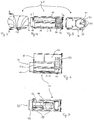
- FIG. 4 shows a perspective illustration of a supply air control device 1 in accordance with a first exemplary embodiment of the present invention.
- the supply air control device 1 comprises a fixed, non-movable part (hereinafter referred to as "stator") - stator 5, which receives a rotatable part (hereinafter referred to as "rotor") - rotor 7.
- the rotor 7 is hollow in the form of a cylinder and has control openings 9, of which in Fig. 1 only one is visible.
- the stator 5 is cuboid on the outside and cylindrical on the inside corresponding to the rotor 7, so that the rotor 7 can be rotated about an axis 11 within the stator 5.
- the stator 5 additionally has two openings, a primary air opening 17 and a secondary air opening 15, each of which has a rectangular shape.
- a tubular connecting piece 19 which has an air supply opening 3 through which supply air enters the supply air control device 1.
- air passes through the opening 3 into the rotor 7 and is then discharged out of the control opening 9 and the secondary air opening 15 out of the supply air control device 1 again.
- the control openings 9 of the rotor 7 are arranged such that, depending on the rotational position of the rotor 7, they let air through the primary air opening 17 and / or secondary air opening 15.
- the rotor 7 is rotatably mounted on an axis of rotation 11, which centrally breaks through a second end face opposite the first end face. This second end face is connected to the stator 5 by screws 13.
- the axis of rotation 11 is rotatably held by an axis holding element 23, which is also connected to the second end face.
- Both the stator 5 and the rotor 7 are made of aluminum profiles. In other exemplary embodiments, these elements, rotor and stator are injection molded, for example from plastic, or molded by other known methods. Both the rotor and the stator can be manufactured in one piece or in several parts.
- FIG. 2 Another perspective view of the supply air control device 1 is illustrated.
- the interior of the supply air control device 1 with the rotor 7 and a further axis of rotation holder 21 is visible through the air supply opening 3.
- the axis of rotation holder 21 holds the axis of rotation 11 in the center.
- the star shape of the axis of rotation holder 21 ensures that the axis of rotation 11 is supported centrally, so that the rotor 7 can rotate about the axis 11.
- the tubular connecting piece 19 is visible, to which, for example, a supply air pipe (not shown) can be connected.
- a supply air pipe not shown
- the primary air opening 17 and the secondary air opening 15 are visible, through which supply air which has entered the rotor 7 through the air supply opening 3 can be discharged.
- supply air is discharged through the primary air opening 17 and / or secondary air opening 15 from the supply air control device.
- the supply air can be divided into any volume proportions between the primary air opening 17 and the secondary air opening 15 by adjusting the corresponding rotational position of the rotor 7. This is achieved in that, depending on the rotational position of the rotor 7, the primary or secondary air opening is closed by the rotor 7, or a part of the control opening 9 (see FIG.
- control opening 9 releases the primary air opening or secondary air opening.
- the control opening 9 can be designed in any way. In some embodiments (not shown), the control opening is circular, in others it is angular, in others it is laid out in a grid, etc.
- FIG. 12 is a sectional view of the supply air control device 31 along a line BB shown in FIG Fig. 3 is shown.
- the supply air control device also has an electromotive drive 50 which is connected to the rotor 37 via an axis of rotation 41.
- a connecting piece 49 is shown which has an air supply opening 33.
- FIG. 5 illustrated front view of the supply air control device 31
- screw connections 51 are visible with those in FIG Fig. 5 visible end face, or the stator 35, is connected to other sides of the supply air control device 31.
- the arrangement of the axis of rotation 41 in the center of the rotor 37 and an axis of rotation holder 53 for the axis of rotation 41 are shown.
- the axis of rotation holder ensures that the axis of rotation 41 is centrally supported, so that the rotor 37 is rotatably supported.
- the in Fig. 6 shown section through the supply air control 31 along one in Fig. 4
- the section axis AA shown shows a section through the stator 35.
- the stator 35 has an air chamber 53 which serves to cool the electromotive drive 50.
- Supply air that enters the rotor 37 through the opening 33 for example through a supply air pipe connected to the connecting piece 49, is passed through a control opening 39 (see FIG. Fig. 7 ) passed into the air chamber 53.
- the supply air generally has a temperature which is below the temperature of the electromotive drive 50 and is therefore suitable for cooling the electromotive drive 50.
- the electromotive drive 50 is connected to the rotor 37 via the axis of rotation 41, so that the rotor 37 can be rotated accordingly with this electromotive drive 50.
- the electric motor drive 50 includes a safety function, so that in an emergency, for example in the event of a power failure or a defect in the electric motor drive 50, the axis of rotation 41 can be decoupled from the drive 50 and manual operation of the supply air control device 31 is thus possible.
- Fig. 7 a schematic sectional view of the supply air control device 31 is shown.
- Supply air passes through the air supply opening 33 into the rotor 37, which has control openings 39.
- the control openings 39 are arranged such that air supplied through the air supply opening 33 is discharged through the control openings 39, depending on the rotational position of the rotor 37, through a primary air opening 47 and / or secondary air opening 45.
- the supplied air is discharged from the supply air control device 31 in a certain ratio through the primary air opening 47 and the secondary air opening 45.
- the ratio depends on the rotational position of the rotor 37, on which in turn the position of the control openings 39 with respect to the primary air opening 47 or the secondary air opening 45 depends.
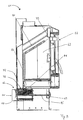
- FIG. 13 illustrates a third embodiment with a furnace 61 with an air supply control device 63 in accordance with the present invention.
- the furnace 61 comprises a combustion chamber 62 in which, for example, fuel is to be burned.
- the supply air control device 63 has a supply air connection 67 through which supply air 65 can be supplied.
- the supply air 65 can be taken from the room air surrounding the furnace 61, or else independently, from the outside, for example as a fresh air supply from outside a building.
- the supply air control device 61 is, for example, a supply air control device as described above in connection with the first and second exemplary embodiments.
- the supply air control device 61 has a primary air opening 71 and a secondary air opening 73, through which the supplied supply air 65 is distributed into the combustion chamber.
- supply air 65 which flows out of the primary air opening 71, reaches a lower region of the combustion chamber 62 of the furnace 61.
- supply air 65 which flows out of the secondary air opening 73, passes through a corresponding secondary air duct 77, which is in the center in a rear region (left in Fig. 8 ) of the furnace 61 is arranged, past the combustion chamber 62 upwards.
- part of the secondary air of the secondary air duct 77 is brought into a glowing zone of the combustion chamber 62 in order to supply combustion in the combustion chamber 62 with air accordingly.
- the secondary air duct 77 extends in an oblique direction in an upper region of the combustion chamber 62 and finally ends in a distribution space 79 in which the Secondary air from the secondary air duct 77 is distributed such that it can fall down as an air curtain over the entire width of a transparent pane 87 of the kiln 61. As a result, the transparent window 87 is rinsed, as it were, and fogging and sooting are prevented. After falling, the secondary air enters a lower area of the combustion chamber 62 in order to supply combustion with the appropriate air there.
- the air supply via the primary air opening 71 and secondary air 73 is controlled by an electric motor or via a handle 69.
- the handle 69 is connected to a rotor in the supply air control device 63 via a connecting rod 75.
- the connecting rod 75 is also rotated and thus also the rotor.
- the supply air 65 is distributed in the supply air control device 62 via the primary air opening 71 and secondary air opening 73 depending on the rotational position of the rotor.
- a targeted control of a combustion process in the combustion chamber 62 is thus possible. For example, in an ignition phase of a fuel, primary air can be led into the combustion chamber from below so that the fuel quickly catches fire.
- the secondary air fulfills two functions in this exemplary embodiment. First, the formation of an air curtain keeps the transparent window 87 clear, in particular fogging and sooting of the transparent window 87 is prevented. And secondly, the secondary air, after it has fallen down on the transparent window 87, provides a corresponding air supply in the lower region of the combustion chamber 62. For example, gases which are produced during the combustion of the fuel are optimally burned.
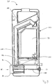
- FIG. 9 4 illustrates a fourth embodiment with a furnace 91 having an air supply control device 93 in accordance with the present invention.
- the kiln 91 comprises a supply air control device 93, the supply air 95 (from the left in FIG Fig. 9 supplied) distributed through a primary air opening 101 and secondary air opening 103 into a combustion chamber 92 of the furnace 91.
- the supply air control device 93 comprises a supply air connection piece 97 and can be controlled automatically by an electric motor drive and also manually by a hand controller 99, which is connected via a connecting rod 105 to a rotor of the supply air control device 93.
- the secondary air emerging from the secondary air opening 103 is passed through a secondary air duct 107, which is behind (left in Fig. 9 )
- the combustion chamber 92 is arranged centrally upwards, ie into an upper region of the combustion chamber 92. In this region, the secondary air duct 107 bends to the right Fig. 9 and is surrounded by a heat exchanger 102.
- the secondary air heats up due to the heat emitted by the combustion chamber 92, so that the secondary air would no longer fall down as desired in the subsequent flushing process via a transparent screen 117.
- the heat exchanger 100 which is connected, for example, to room air that surrounds the furnace 91, extracts heat from the secondary air and releases it into the room air, so that due to the cooling of the secondary air, it has a sufficiently high density to function as a purge Clear lens 117 to meet.
- the supply air control device can be controlled automatically or manually.
- the supply air control device includes, for example, emergency operation, so that if the electromotive drive is defective or there is a power failure, the air supply can be regulated manually using a handle.
- the furnace and / or the supply air control device comprises an electronic control, which in turn comprises a smoke sensor, for example.
- the smoke sensor is installed, for example, in a flue gas duct in the furnace, through which flue gas generated during combustion is derived, and measures, for example, the smoke density.
- Temperature sensors can also be attached, for example in the flue gas duct, but also in a supply air duct and / or in a primary air duct and secondary air duct.
- at least one of the sensors mentioned can be present, which then transmits corresponding parameters to the electronic ones Provide control so that this causes the distribution of the supply air into primary air and secondary air accordingly. This is done, for example, by sending corresponding control signals to an electric motor drive, which then brings a rotor of the supply air control device into one position (rotational position) so that the desired ratio of primary air to secondary air is achieved.
Landscapes
- Engineering & Computer Science (AREA)
- Chemical & Material Sciences (AREA)
- Combustion & Propulsion (AREA)
- Mechanical Engineering (AREA)
- General Engineering & Computer Science (AREA)
- Muffle Furnaces And Rotary Kilns (AREA)
- Solid-Fuel Combustion (AREA)
- Furnace Details (AREA)
Description
Die vorliegende Erfindung bezieht sich auf eine Zuluftsteuervorrichtung zum Steuern von Primärluft und/oder Sekundärluft für eine Heizeinrichtung, wie beispielsweise einen Ofen bzw. Brennofen.The present invention relates to a supply air control device for controlling primary air and / or secondary air for a heating device, such as a furnace.
Es sind allgemein verschiedenartige Heizeinrichtungen, in denen Brennmittel verbrannt werden können, bekannt, wie beispielsweise Kachelöfen, Kaminöfen, Pelletöfen und auch Zentralheizungen, die teilweise auch Mischformen vorgenannter Öfen sein können.Various types of heating devices in which fuel can be burned are generally known, such as, for example, tiled stoves, wood-burning stoves, pellet stoves and also central heating systems, some of which can also be mixed forms of the aforementioned stoves.
Insbesondere sind beispielsweise moderne Kaminöfen für den Wohnbereich bekannt, bei denen eine Klarsichtscheibe, die sich zum Beispiel in einer Ofentür befindet, den Blick auf das Feuer frei gibt. Zusätzlich ist beispielsweise aus den Offenlegungsschritten
Die
Die
Die
Die
Die vorgenannte Steuerung der Luftzufuhr erfordert eine separate Steuervorrichtung jeweils für Primärluft und Sekundärluft.The aforementioned control of the air supply requires a separate control device for primary air and secondary air, respectively.
Die vorgenannte Steuerung der Luftzufuhr - insbesondere des oben genannten Schiebereglers - bedarf außerdem eines aufmerksamen Benutzers, der den Regler per Hand betätigt. Dies setzt neben eines gewissen Wissens des Benutzers über den Zusammenhang zwischen Verbrennung und Primär- und Sekundärluftzufuhr auch die Anwesenheit und das Aktivwerden des Benutzers voraus. Dies ist allerdings wenig wünschenswert. Insbesondere bei Brennöfen, wie Scheitholzkaminöfen ist eine Steuerung, die ein automatisiertes Steuern der Luftzufuhr ermöglicht, vorteilhaft.The aforementioned control of the air supply - in particular the above-mentioned slider - also requires an attentive user who operates the controller by hand. In addition to a certain knowledge of the user about the connection between combustion and primary and secondary air supply, this also requires the presence and the activity of the user. However, this is not very desirable. A control that enables automated control of the air supply is advantageous, in particular, in stoves such as firewood stoves.
Aufgabe der vorliegenden Erfindung ist es, eine verbesserte Zuluftsteuervorrichtung bereitzustellen.The object of the present invention is to provide an improved supply air control device.
Nach einem ersten Aspekt stellt die vorliegenden Erfindung eine Zuluftsteuervorrichtung für einen Brennofen bereit, wobei die Zuluftsteuervorrichtung eine Luftzuführöffnung, durch die Zuluft in die Zuluftsteuervorrichtung eingeleitet wird, eine Primärluftöffnung, durch die Zuluft als Primärluft aus der Zuluftsteuervorrichtung ausgeleitet werden kann, eine Sekundärluftöffnung, durch die Zuluft als Sekundärluft aus der Zuluftsteuervorrichtung ausgeleitet werden, und ein erstes und ein zweites Regelelement umfasst. Die Zuluft wird in Abhängigkeit einer Drehung wenigstens eines Regelelements als Primärluft und/oder als Sekundärluft durch die Primärluftöffnung bzw. Sekundärluftöffnung ausgeleitet.According to a first aspect, the present invention provides a supply air control device for a kiln, the supply air control device having an air supply opening through which supply air is introduced into the supply air control device, a primary air opening through which supply air can be discharged as primary air from the supply air control device, a secondary air opening through which Supply air can be discharged as secondary air from the supply air control device, and comprises a first and a second control element. Depending on a rotation of at least one control element, the supply air is discharged as primary air and / or as secondary air through the primary air opening or secondary air opening.
Nach einem zweiten Aspekt stellt die vorliegende Erfindung einen Brennofen für die Verbrennung von einem Brennmittel bereit, wobei der Brennofen einen Brennraum und eine Zuluftsteuervorrichtung umfasst, die für die Verbrennung des Brennmittels in dem Brennraum zugeführte Primärluft und Sekundärluft steuert.According to a second aspect, the present invention provides a furnace for the combustion of a fuel, the furnace comprising a combustion chamber and a supply air control device which controls primary air and secondary air supplied for the combustion of the fuel in the combustion chamber.
Weitere Aspekte und Merkmale der Erfindung ergeben sich aus den abhängigen Ansprüchen, der beigefügten Zeichnung und der nachfolgenden Beschreibung bevorzugter Ausführungsbeispiele.Further aspects and features of the invention result from the dependent claims, the attached drawing and the following description of preferred exemplary embodiments.
Ausführungsbeispiele der Erfindung werden nun beispielhaft und unter Bezugnahme auf die beigefügte Zeichnung beschreiben, in der:
-
Fig. 1 eine perspektivische Ansicht einer Zuluftsteuervorrichtung eines ersten Ausführungsbeispiels in Übereinstimmung mit der vorliegenden Erfindung veranschaulicht; -
Fig. 2 eine weitere perspektivische Ansicht der inFig. 1 gezeigten Zuluftsteuervorrichtung in Übereinstimmung mit der vorliegenden Erfindung veranschaulicht; -
Fig. 3 eine Rückansicht einer Zuluftsteuervorrichtung eines zweiten Ausführungsbeispiels in Übereinstimmung mit der vorliegenden Erfindung zeigt; -
Fig. 4 eine Schnittansicht entlang der inFig. 3 gezeigten Linie B-B der Zuluftsteuervorrichtung des zweiten Ausführungsbeispiels in Übereinstimmung mit der vorliegenden Erfindung zeigt; -
Fig. 5 eine Vorderansicht der Zuluftsteuervorrichtung des zweiten Ausführungsbeispiels in Übereinstimmung mit der vorliegenden Erfindung zeigt; -
Fig. 6 eine Schnittansicht entlang der inFig. 4 gezeigten Linie A-A der Zuluftsteuervorrichtung des zweiten Ausführungsbeispiels in Übereinstimmung mit der vorliegenden Erfindung zeigt; -
Fig. 7 eine schematische Ansicht der Zuluftsteuervorrichtung des zweiten Ausführungsbeispiels in Übereinstimmung mit der vorliegenden Erfindung zeigt; -
Fig. 8 ein drittes Ausführungsbeispiel mit einem Brennofen mit einer Zuluftsteuervorrichtung in Übereinstimmung mit der vorliegenden Erfindung veranschaulicht; und -
Fig. 9 ein viertes Ausführungsbeispiel mit einem Brennofen mit einer Zuluftsteuervorrichtung in Übereinstimmung mit der vorliegenden Erfindung veranschaulicht.
-
Fig. 1 Figure 3 illustrates a perspective view of a supply air control device of a first embodiment in accordance with the present invention; -
Fig. 2 another perspective view of the inFig. 1 shown supply air control device in accordance with the present invention; -
Fig. 3 Figure 3 shows a rear view of a supply air control device of a second embodiment in accordance with the present invention; -
Fig. 4 a sectional view along the inFig. 3 line BB shown of the supply air control device of the second embodiment in accordance with the present invention; -
Fig. 5 Figure 4 shows a front view of the supply air control device of the second embodiment in accordance with the present invention; -
Fig. 6 a sectional view along the inFig. 4 line AA of the supply air control device of the second embodiment in accordance with the present invention; -
Fig. 7 Figure 3 shows a schematic view of the supply air control device of the second embodiment in accordance with the present invention; -
Fig. 8 a third embodiment with a kiln with a supply air control device in accordance with the present invention illustrates; and -
Fig. 9 illustrates a fourth embodiment with a kiln with a supply air control device in accordance with the present invention.
In
Nach den Ausführungsbeispielen gibt es Öfen bzw. Brennöfen, die als Brennmittel beispielsweise Holz benutzen, in den verschiedensten Ausführungsformen. Es existieren Kachelöfen, Kaminöfen, Pelletöfen und auch Mischformen, wie beispielsweise Kaminöfen, die auch als Pelletöfen betrieben werden können. Zusätzlich unterscheiden sich die Brennöfen in ihrem Zweck. In manchen Ausführungsformen, haben Brennöfen nur den Zweck in einem Wohnraum Wärme zu erzeugen. Andere Brennöfen hingegen umfassen beispielsweise zusätzlich ein Backfach und wieder andere dienen sogar als Zentralheizung. Auch hier sind wieder beliebige Mischformen realisiert. Wie beispielsweise ein Kaminöfen, der eine Klarsichtscheibe an seiner Front umfasst und somit als Blickfang in einem Wohnraum dient und zusätzlich noch wasserführend ist, um als Zentralheizung dienen zu können und eventuell sogar noch Pellets als Brennmittel verwendet, damit die Brennmittelzufuhr weitestgehend automatisiert ablaufen kann.According to the exemplary embodiments, there are ovens or kilns that act as fuel use wood, for example, in a wide variety of designs. There are tiled stoves, stoves, pellet stoves and also mixed forms, such as stoves, which can also be operated as pellet stoves. In addition, the kilns differ in their purpose. In some embodiments, stoves are only used to generate heat in a living space. Other kilns, on the other hand, also include a baking compartment, for example, and others even serve as central heating. Here, too, any combination is possible. Such as a wood-burning stove, which has a transparent window on its front and thus serves as an eye-catcher in a living room and is also water-bearing to serve as central heating and possibly even uses pellets as fuel so that the fuel supply can be largely automated.
Als Brennmittel werden in den Ausführungsbeispielen beispielsweise auf Biomasse basierende Brennmittel benutzt, wie zum Beispiel Holz in Form von Holzscheiten, Holzabfälle, die beispielsweise zu Pellets gepresst sind, aber auch Holzbriketts, Grobhackgut, Feinhackgut, Häckselgut oder Halmgutpellets.Biomass-based fuels are used as fuel in the exemplary embodiments, for example wood in the form of logs, wood waste which is pressed, for example, into pellets, but also wood briquettes, coarse wood chips, fine wood chips, chopped material or stalk material pellets.
Für eine optimale Verbrennung von Brennmitteln, wie sie beispielsweise oben genannt sind, ist neben anderen Einflussgrößen (Parametern), wie Form eines Brennraumes eines Brennofens und beispielsweise die Anordnung des Brennmittels in dem Brennraum eines Brennofens, eine wichtige Einflussgröße die Luftzufuhr. In manchen Ausführungsbeispielen wird Luft beispielsweise aus der Raumluft, die einen Brennofen umgibt, genommen. In anderen hingegen stammt die zugeführte Luft aus einem nicht abgeschlossenen Raum, beispielsweise von außerhalb eines Hauses, also aus der "freien Natur".In addition to other influencing variables (parameters), such as the shape of a combustion chamber of a furnace and, for example, the arrangement of the fuel in the combustion chamber of a furnace, an important influencing variable for an optimal combustion of fuels, such as those mentioned above, is the air supply. In some embodiments, for example, air is taken from the room air surrounding a furnace. In others, on the other hand, the air supplied comes from a room that is not closed off, for example from outside a house, that is, from "free nature".
Bei der Verbrennung von Brennmitteln, insbesondere von Biomasse, treten verschiedene Effekte auf. Beispielsweise kann die Qualität eines Brennmittels aufgrund unterschiedlicher Brennmittelarten variieren - wie es beispielsweise bei unterschiedlichen Holzarten der Fall ist - oder aber die Qualität des Brennmittels kann innerhalb einer Brennmittelart unterschiedlich sein - wie beispielsweise bei Pellets, die aus gepressten Holzabfällen bestehen. Daher ist es notwendig die Luftzufuhr für den Brennofen an das Brennmittel entsprechend anzupassen.Various effects occur when burning fuels, especially biomass. For example, the quality of a fuel can vary due to different types of fuel - as is the case for example with different types of wood - or the quality of the fuel can be different within one type of fuel - such as with pellets, which consist of compressed wood waste. It is therefore necessary to adapt the air supply for the furnace to the fuel accordingly.
Weiterhin wird das Verbrennen (Brennvorgang) von Brennmittel auch durch das Einbringen des Brennmittels und die Anordnung des Brennmittels in einen Brennraum eines Brennofens beeinflusst. Beispielsweise läuft eine Verbrennung von aufeinandergelegten Holzscheiten in einem Brennraum anders ab, als die Verbrennung von Pellets in einem Pelletofen, bei dem die Pellets auch noch automatisch nachgeliefert werden.Furthermore, the burning (burning process) of fuel is also influenced by the introduction of the fuel and the arrangement of the fuel in a combustion chamber of a furnace. For example, the burning of stacked logs in a combustion chamber is different from the burning of pellets in a pellet stove, in which the pellets are also automatically supplied.
Zusätzlich hat ein Brennvorgang typischerweise unterschiedliche Brennphasen. Beispielsweise gibt es eine Entzündungsphase, in der Brennmittel in Brand gesetzt werden, dann eine stabile Brennphase, in der vorhandenes Brennmittel abgebrannt wird, eventuell eine "Nachlegphase" in der neues Brennmittel nachgelegt wird - wo also in dem Brennraum verbranntes, angebranntes, glühendes und unverbranntes Brennmittel koexistiert - und eine Ausbrennphase in der Brennmittel vollständig zu Asche verbrennen soll. Logischerweise ist die Temperatur des Brennmittels, der entsprechenden Flamme, bzw. Glut, und des Brennraums des Brennofens und die Luft in dem Brennraum unterschiedlich. Dementsprechend ist es wünschenswert für jede einzelne Situation die Luftzufuhr zu dem Brennvorgang entsprechend zu steuern.In addition, a burning process typically has different burning phases. For example, there is an ignition phase in which the fuel is set on fire, then a stable burning phase in which the existing fuel is burned off, possibly a "refill phase" in which new fuel is added - in other words, where burned, burnt, burned and red-hot in the combustion chamber Fuel coexists - and a burnout phase in which the fuel is to burn completely to ashes. Logically, the temperature of the fuel, the corresponding flame or ember, and the combustion chamber of the furnace and the air in the combustion chamber are different. Accordingly, it is desirable to control the air supply to the burning process accordingly for each individual situation.
Weiterhin kann der Brennvorgang eines Brennmittels, beispielsweise eines Holzscheites oder Holzpellets, oder aber auch anderer Brennmittel, die aus Biomasse bestehen, aufgeteilt werden: i) eine Vergasung von Brennmittel, und ii) Ausbrand der Brenngase.Furthermore, the burning process of a fuel, for example a log or wood pellet, or also other fuels that consist of biomass, can be divided up: i) gasification of the fuel, and ii) combustion of the fuel gases.
Die Vergasung von Brennmittel geschieht in manchen Ausführungsformen auf einem Brennrost, der in einem unteren Teil des Brennofens angeordnet ist. Auf diesem Brennrost wird Brennmittel angeordnet. Dieses Brennmittel wird in Brand versetzt. Durch die Verbrennung des Brennmittels wird nicht nur das Brennmittel erst in Glut und dann in Asche umgesetzt, sondern es entstehen auch durch die hohe Temperatur des Brennmittels Gase, die im Zuge einer optimalen Verbrennung verbrannt werden sollten. Dadurch entstehen zwei Bereiche bei der Verbrennung - ein unterer in dem das Brennmittel selbst brennt und glüht und ein oberer in dem die nach oben steigenden Gase verbrannt werden. In manchen Ausführungsbeispielen werden diese Bereiche einzeln mit entsprechender Luft versorgt. Der untere Bereich mit Primärluft und der obere Bereich, in dem die Brenngase verbrennen, mit Sekundärluft, wodurch eine optimale Verbrennung gefördert wird.In some embodiments, the gasification of fuel occurs on a firing grate, which is arranged in a lower part of the firing furnace. Fuel is placed on this firing grate. This fuel is set on fire. The combustion of the fuel not only converts the fuel into embers and then ashes, but it also creates gases due to the high temperature of the fuel, which should be burned in the course of optimal combustion. This creates two areas during combustion - a lower one in which the fuel burns and glows and an upper one in which the gases rising up are burned. In some exemplary embodiments, these areas are individually supplied with appropriate air. The lower area with primary air and the upper area where the combustion gases burn, with secondary air, which promotes optimal combustion.
Eine unterschiedliche Versorgung des Brennvorgangs mit Primär- und Sekundärluft ergibt sich aus den oben genannten Aspekten. So ist es beispielsweise in der Entzündungsphase des Brennmittels sinnvoll, in erster Linie Primärluft zuzuführen, damit das Brennmittel schnell in Brand gesetzt wird und eine Hohe Temperatur erreicht. Brennt das Brennmittel erst einmal, so sollte die Primärluftversorgung nur noch so gut sein, dass der Brennvorgang am Leben gehalten wird, da ansonsten bei zu starker Versorgung das Brennmittel zu schnell verbrannt wird und die entstehende Wärme in erster Linie an das durch die Verbrennung entstehende Rauchgas und nicht mehr an die Umgebung oder zum Beispiel einen wasserführenden Wärmetauscher abgegeben wird. Dafür ist es dann sinnvoll die Sekundärluftversorgung entsprechend der Verbrennung anzupassen. Natürlich ist je nach Brennmittel und Verbrennungsphase jede Mischform von Primärluftzufuhr und Sekundärluftzufuhr wünschenswert.A different supply of the combustion process with primary and secondary air results from the above-mentioned aspects. In the ignition phase of the fuel, for example, it makes sense to primarily supply primary air so that the fuel is set on fire quickly and reaches a high temperature. If the fuel burns once, the primary air supply should only be so good that the burning process is kept alive, otherwise the fuel will be burned too quickly if the supply is too strong and the heat generated is primarily due to the flue gas produced by the combustion and is no longer released into the environment or, for example, a water-bearing heat exchanger. It makes sense to adjust the secondary air supply to match the combustion. Of course, depending on the fuel and combustion phase, any combination of primary air supply and secondary air supply is desirable.
Zusätzlich ist es in manchen Ausführungsformen, insbesondere bei Brennöfen, die auch als Zentralheizung dienen, aber auch bei anderen Brennöfen, wünschenswert eine möglichste konstante Temperatur bei der Verbrennung von Brennmittel zu erhalten. Auch dafür ist es notwendig, insbesondere aufgrund der oben genannten Einflüsse, die aus der Beschaffenheit des Brennmittels, die Anordnung des Brennmittels in dem Brennraum, die Beschaffenheit des Brennraumes, etc., resultieren, die Luftzufuhr entsprechend zu steuern.In addition, in some embodiments, in particular in the case of kilns which also serve as central heating, but also in the case of other kilns, it is desirable to maintain the most constant temperature possible when burning fuel. It is also necessary to control the air supply accordingly, in particular due to the above-mentioned influences resulting from the nature of the fuel, the arrangement of the fuel in the combustion chamber, the nature of the combustion chamber, etc.
Diese wünschenswerte Steuerung der Primärluftzufuhr und Sekundärluftzufuhr, die einfach händisch oder automatisch bedienbar ist, wird in einigen Ausführungsbeispielen mit einer einzigen erfindungsgemäßen Zuluftsteuervorrichtung für einen Brennofen erreicht.This desirable control of the primary air supply and secondary air supply, which can be operated simply manually or automatically, is achieved in some exemplary embodiments with a single supply air control device for a kiln according to the invention.
In manchen Ausführungsbeispielen umfasst die Zuluftsteuervorrichtung eine Luftzufuhröffnung, durch welche Zuluft in die Zuluftsteuervorrichtung eingeleitet wird. Die Zuluft stammt in manchen Ausführungsbeispielen aus der näheren Umgebung, beispielsweise aus der die Luftzufuhrregelvorrichtung umgebenden Raumluft. In anderen Ausführungsbeispielen wird die Zuluft aus der freien Natur oder einem anderen Raum entnommen.In some exemplary embodiments, the supply air control device comprises an air supply opening through which supply air is introduced into the supply air control device. In some exemplary embodiments, the supply air comes from the immediate vicinity, for example from the ambient air surrounding the air supply control device. In other exemplary embodiments, the supply air is taken from the wild or from another room.
Die Zuluftsteuervorrichtung hat beispielsweise eine quaderförmige, oder rohrförmige, längliche Form. Es sind aber auch andere Formen, wie zum Beispiel würfel- oder kugelförmig realisiert. An einer Seite, oder einer Stelle, der Zuluftsteuervorrichtung ist die Luftzufuhröffnung angeordnet. Dies kann beispielsweise bei einer länglichen Form an einer Stirnseite der Zuluftsteuervorrichtung sein.The supply air control device has, for example, a cuboid, or tubular, elongated shape. But there are also other shapes, such as cube-shaped or spherical realized. The air supply opening is arranged on one side, or at one point, of the supply air control device. This can be, for example, in the case of an elongated shape on an end face of the supply air control device.
Die Luftzufuhröffnung ist in manchen Ausführungsbeispielen kreisförmig ausgebildet, in anderen hingegen rechteckig. Der Durchmesser der Luftzufuhröffnung variiert in den Ausführungsbeispielen, beispielsweise von 5cm bis 20cm. Es sind aber auch andere Durchmesser möglich, die eine ausreichende Luftzufuhr ermöglichen.The air supply opening is circular in some embodiments, but rectangular in others. The diameter of the air supply opening varies in the exemplary embodiments, for example from 5 cm to 20 cm. However, other diameters are also possible which allow an adequate air supply.
Weiterhin weist die Luftzufuhrregelvorrichtung in einigen Ausführungsbeispielen eine Primärluftöffnung und eine Sekundärluftöffnung auf, durch die zugeführte Zuluft als Primärluft bzw. Sekundärluft ausgeleitet wird. Die Zuluft wird also in Primärluft und Sekundärluft in der Zuluftsteuervorrichtung aufgeteilt.Furthermore, in some exemplary embodiments, the air supply control device has a primary air opening and a secondary air opening, through which the supplied air is discharged as primary air or secondary air. The supply air is thus divided into primary air and secondary air in the supply air control device.
Diese Aufteilung übernimmt in manchen Ausführungsbeispielen ein erstes und ein zweites Regelelement. Die beiden Regelelemente sind beispielsweise derart relativ zueinander drehbar angeordnet, dass die Aufteilung der Zuluft in Primärluft und Sekundärluft in Abhängigkeit einer Drehung bzw. einer Drehlage eines Regelelements bezüglich des anderen Regelelements geschieht. Diese Drehung bzw. Drehlage des Regelelements hat beispielsweise zur Folge, dass die Zuluft vollständig als Primärluft aus der Zuluftsteuervorrichtung ausgeleitet wird. Eine andere Drehung bzw. Drehlage des Regelelements hat hingegen beispielsweise zur Folge, dass die Zuluft vollständig als Sekundärluft ausgeleitet wird. Wieder eine andere Drehung bzw. Drehlage sorgt dafür, dass eine Hälfte der Zuluft als Primärluft und die andere Hälfte als Sekundärluft ausgeleitet wird. Bei wieder anderen Drehungen bzw. Drehlagen sind beispielsweise Aufteilungsverhältnisse der Zuluft von 20 zu 80 oder 10 zu 90 in Primärluft zu Sekundärluft realisiert. Je nach der ausgeführten Drehung bzw. der Drehlage eines Regelelements kann also jede beliebige Aufteilung der Zuluft in Primärluft und Sekundärluft erreicht werden.In some exemplary embodiments, this division takes over a first and a second control element. For example, the two control elements are arranged such that they can be rotated relative to one another such that the supply air is divided into primary air and secondary air as a function of a rotation or a rotational position of one control element with respect to the other control element. This rotation or rotational position of the control element has the consequence, for example, that the supply air is completely discharged as primary air from the supply air control device. A different rotation or rotational position of the control element, however, has the consequence, for example, that the supply air is completely discharged as secondary air. Another rotation or rotational position ensures that half of the supply air is discharged as primary air and the other half as secondary air. With other rotations or rotational positions, for example, distribution ratios of the supply air of 20 to 80 or 10 to 90 in primary air to secondary air are realized. Depending on the rotation or the rotational position of a control element, any division of the supply air into primary air and secondary air can be achieved.
In manchen Ausführungsbeispielen umfasst ein Regelement Steueröffnungen oder wenigstens eine Steueröffnung, die beispielsweise so angeordnet sind, dass Zuluft entsprechend durch die Primärluftöffnung und/oder Sekundärluftöffnung geleitet werden kann.In some exemplary embodiments, a regulating element comprises control openings or at least one control opening, which are arranged, for example, in such a way that supply air can be passed accordingly through the primary air opening and / or secondary air opening.
In machen Ausführungsbeispielen umfasst das erste Regelelement beispielsweise ein stationäres Element und das zweite Regelelement ein Drehelement. Das Drehelement ist beispielsweise drehbar in dem stationären Element angeordnet. Das stationäre Element ist beispielsweise fest in einem Brennofen angeordnet, während das Drehelement sich in dem stationären Element oder um das stationäre Element drehen kann. Vorzugsweise ist das Drehelement so dicht mit dem stationären Element verbunden, dass es noch leicht drehbar ist, aber die Zuluft im wesentlichen aus der Primärluftöffnung und/oder Sekundärluftöffnung entweicht. Das Drehelement ist beispielsweise zylinderförmig ausgebildet und ist drehbar in einem entsprechenden zylinderförmigen Hohlraum des stationären Elements angeordnet. In anderen Ausführungsbeispielen hingegen ist das Drehelement beispielsweise um ein zylinderförmiges stationäres Element herum angeordnet. Die äußere Form des stationären Elements ist in manchen Ausführungsformen beliebig und kann beispielsweise quaderförmig sein, was beispielsweise den Einbau in den Brennofen erleichtert. In anderen Ausführungsbeispielen ist das stationäre Element beispielsweise als Hohlzylinder ausgebildet und weist an seiner Außenseite Montagebereiche auf.In some exemplary embodiments, the first control element comprises, for example, a stationary element and the second control element comprises a rotary element. The rotating element is, for example, rotatably arranged in the stationary element. The stationary element is, for example, fixedly arranged in a kiln, while the rotating element can rotate in the stationary element or around the stationary element. The rotary element is preferably connected so tightly to the stationary element that it can still be easily rotated, but the supply air essentially escapes from the primary air opening and / or secondary air opening. The rotating element is, for example, cylindrical and is rotatably arranged in a corresponding cylindrical cavity of the stationary element. In other exemplary embodiments, however, the rotary element is arranged, for example, around a cylindrical stationary element. The outer shape of the stationary element is arbitrary in some embodiments and can, for example, be cuboid, which, for example, facilitates installation in the kiln. In other exemplary embodiments, the stationary element is designed, for example, as a hollow cylinder and has assembly areas on its outside.
In manchen Ausführungsbeispielen weist das stationäre Element die Primärluftöffnung und die Sekundärluftöffnung auf. Hier wird beispielsweise die Zuluft durch die Luftzufuhröffnung in die Zuluftsteuervorrichtung, bzw. in das Drehelement eingeleitet, welches beispielsweise Steueröffnungen umfasst, die entsprechend der Primärluftöffnung und Sekundärluftöffnung des stationären Elements angeordnet sind. Je nach Drehlage des Drehelements bezüglich des stationären Elements und damit auch der Lage der Steueröffnungen bezüglich der Primärluftöffnung bzw. Sekundärluftöffnung, kann dann die Luft durch die Primärluftöffnung und/oder durch die Sekundärluftöffnung in dem stationären Element entweichen. Je nach Drehlage des Drehelements werden die Primärluftöffnung und Sekundärluftöffnung in dem stationären Element ganz oder teilweise verdeckt bzw. sind ganz oder teilweise offen, d.h. die Steueröffnung(en) befinden sich in einer der Primärluftöffnung und/oder Sekundärluftöffnung entsprechenden Position. Das Drehelement ist also so ausgebildet, dass je nach Drehlage bzw. Rotationslage in dem stationären Element die eingeleitete Zuluft durch die Primärluftöffnung und/oder Sekundärluftöffnung ausleitet.In some embodiments, the stationary element has the primary air opening and the secondary air opening. Here, for example, the supply air is introduced through the air supply opening into the supply air control device or into the rotary element, which for example comprises control openings which are arranged corresponding to the primary air opening and secondary air opening of the stationary element. Depending on the rotational position of the rotary element with respect to the stationary element and thus also the position of the control openings with respect to the primary air opening or secondary air opening, the air can then escape through the primary air opening and / or through the secondary air opening in the stationary element. Depending on the rotational position of the rotating element, the primary air opening and secondary air opening in the stationary element are completely or partially covered or are completely or partially open, i.e. the control opening (s) are in a position corresponding to the primary air opening and / or secondary air opening. The rotary element is thus designed such that, depending on the rotational position or rotational position in the stationary element, the incoming air is discharged through the primary air opening and / or secondary air opening.
In manchen Ausführungsbeispielen ist das Drehelement zylinderförmig ausgebildet, weist einen Zylindermantel auf und ist an einem Ende, d.h. einer Stirnseite des Zylindermantels, verschlossen. An der dem verschlossenen Ende gegenüberliegenden Seite ist das Drehelement offen, sodass dort die Zuluft eingeleitet werden kann. Weiterhin weist das Drehelement beispielsweise zwei schlitzförmige Öffnungen bzw. Steueröffnungen in dem Zylindermantel auf, die jeweils in Höhe der Primärluftöffnung und Sekundärluftöffnung in dem stationären Element angeordnet sind. Die beiden schlitzförmigen Öffnungen erstrecken sich beispielsweise mit der längeren Seite in Polarrichtung und sind beispielsweise in Polarrichtung doppelt so lang wie die Primärluft- bzw. Sekundärluftöffnung. In radialer Richtung des Drehelements betrachtet, überlappen sich die schlitzförmigen Öffnungen zur Hälfte. Somit kann zum Beispiel das Drehelement in eine Stellung gedreht werden, in der jeweils eine schlitzförmige Öffnung zur Hälfte unterhalb der Primärluft- bzw. Sekundärluftöffnung des stationären Elements angeordnet ist. In dieser Stellung wird die Zuluft also je zur Hälfte aus der Primärluftöffnung bzw. Sekundärluftöffnung ausgeleitet. Dreht man das Drehelement aus dieser Drehlage heraus in eine Richtung weiter, so wird sich eine der beiden schlitzförmigen Öffnungen so in Polarrichtung weiterbewegen, dass sie weiterhin beispielsweise die Primärluftöffnung offen lässt, während die andere schlitzförmige Öffnung - in diesem Beispiel - die Sekundärluftöffnung verkleinert, bis schließlich eine Stellung erreicht ist, in der nur noch die Primärluftöffnung offen ist und die Sekundärluftöffnung vollständig verschlossen ist. Durch weiteres Drehen wird dann die Primärluftöffnung ebenfalls verschlossen.In some embodiments, the rotating element is cylindrical, has a cylinder jacket and is closed at one end, ie an end face of the cylinder jacket. The rotary element is open on the side opposite the closed end, so that the supply air can be introduced there. Furthermore, the rotating element has, for example, two slot-shaped openings or control openings in the cylinder jacket, which are each arranged at the level of the primary air opening and secondary air opening in the stationary element. The two slot-shaped openings extend, for example, with the longer side in the polar direction and are, for example, twice as long in the polar direction as the primary air or secondary air opening. When viewed in the radial direction of the rotary element, the slot-shaped openings overlap by half. Thus, for example, the rotating element can be rotated into a position in which a slot-shaped opening is arranged half below the primary air or secondary air opening of the stationary element. In this position, half of the supply air is discharged from the primary air opening and half from the secondary air opening. If you turn the rotating element out of this rotational position in one direction, one of the two slot-shaped openings will continue to move in the polar direction in such a way that it continues to leave the primary air opening open, for example, while the other slot-shaped opening - in this example - reduces the secondary air opening until finally a position is reached in which only the primary air opening is open and the secondary air opening is completely closed. The primary air opening is then also closed by further turning.
In manchen Ausführungsbeispielen weist die Zuluftsteuervorrichtung zusätzlich ein Stellmittel auf. Dieses Stellmittel ist beispielsweise mit einem Regelelement, beispielsweise dem Drehelement, verbunden. Mit dem Stellmittel kann das Drehelement in die gewünschte Drehlage gedreht werden. Das Stellmittel umfasst in manchen Ausführungsformen eine Achse, die mit der Drehachse des Drehelements verbunden ist und in manchen Ausführungsbeispielen noch zusätzlich beispielsweise einen Handgriff zum Drehen oder ein elektromotorisches Antriebsmittel, wie beispielsweise einen elektrischen Stellmotor.In some exemplary embodiments, the supply air control device additionally has an adjusting means. This actuating means is connected, for example, to a control element, for example the rotary element. The rotary element can be rotated into the desired rotational position with the adjusting means. In some embodiments, the adjusting means comprises an axis, which is connected to the axis of rotation of the rotating element and, in some embodiments, additionally, for example, a handle for turning or an electromotive drive means, such as an electric servomotor.
In manchen Ausführungsbeispielen umfasst die Zuluftsteuervorrichtung auch eine elektronische Steuerung die beispielsweise ein elektrisches bzw. elektromotorisches Antriebsmittel oder das Stellmittel steuert. Beispielsweise steuert die elektronische Steuerung die ausgeleitete Primärluft und/oder Sekundärluft in Abhängigkeit von wenigstens einem Parameter, der einen, beispielsweise oben beschriebenen, Brennvorgang charakterisiert. So ein Parameter kann zum Beispiel über einen Rauchgassensor gewonnen werden, der das bei der Verbrennung eines Brennmittels entstehende Rauchgas analysiert. Mit diesem Parameter kann die elektronische Steuerung beispielsweise feststellen, dass mehr Primärluft für eine bessere Verbrennung vonnöten ist und demzufolge beispielsweise das Drehelement in eine entsprechende Drehlage mit Hilfe des Stellmittels bringen, die eine stärkere Primärluftzufuhr zur Folge hat. Generell kann beispielsweise die elektronische Steuerung in einer Startphase eines Brennvorgangs und/oder in der Entzündungsphase des Brennmittels mehr Primärluft als Sekundärluft aus der Zuluftsteuervorrichtung ausleiten und damit für einen optimalen Brennvorgang sorgen.In some exemplary embodiments, the supply air control device also comprises an electronic control which, for example, controls an electric or electromotive drive means or the actuating means. For example, the electronic controls Control of the discharged primary air and / or secondary air as a function of at least one parameter that characterizes a combustion process, for example described above. Such a parameter can be obtained, for example, via a flue gas sensor that analyzes the flue gas generated when a fuel is burned. With this parameter, the electronic control can determine, for example, that more primary air is required for better combustion and consequently, for example, bring the rotary element into a corresponding rotational position with the aid of the actuating means, which results in a stronger primary air supply. In general, the electronic control can, for example, discharge more primary air than secondary air from the supply air control device in a starting phase of a combustion process and / or in the ignition phase of the fuel and thus ensure an optimal combustion process.
In manchen Ausführungsbeispielen wird die ausgeleitete Primärluft der einer Verbrennung in einem Brennraum eines Ofens abgewandten Seite zugeführt. Die Verbrennung eines Brennmittels weist, wie oben ausgeführt, einen Bereich auf, in dem sich das noch feste Brennmittel in der Verbrennung befindet und einen oberen Bereich, in dem die durch die Verbrennung des Brennmittels entstehenden Gase verbrannt werden. Die der Verbrennung abgewandte Seite ist die von unten auf das brennende Brennmittel in Richtung der aufsteigenden Gase betrachtete Seite. Während die der Verbrennung zugewandte Seite, die in Blickrichtung gegen die aufsteigenden Verbrennungsgase liegende Seite ist. Beispielsweise wird in manchen Ausführungsbeispielen brennendes Brennmittel, welches sich auf einem Brennrost in einem Brennofen befindet, von unterhalb des Brennrostes mit Primärluft versorgt, während es von oberhalb mit Sekundärluft versorgt wird.In some exemplary embodiments, the discharged primary air is supplied to the side facing away from combustion in a combustion chamber of a furnace. As stated above, the combustion of a fuel has an area in which the still solid fuel is in the combustion and an upper area in which the gases resulting from the combustion of the fuel are burned. The side facing away from the combustion is the side viewed from below of the burning fuel in the direction of the rising gases. While the side facing the combustion is the side facing the rising combustion gases. For example, in some exemplary embodiments, burning fuel, which is located on a firing grate in a firing furnace, is supplied with primary air from below the firing grate, while it is supplied with secondary air from above.
In manchen Ausführungsbeispielen umfasst ein Brennofen einen Brennraum und eine Zuluftsteuervorrichtung, wie sie beispielsweise weiter oben beschrieben wurde. In manchen derartigen Ausführungsbeispielen wird Primärluft beispielsweise in einen unteren Bereich des Brennraumes geleitet, während Sekundärluft beispielsweise in einen oberen Bereich des Brennraumes geleitet wird. Der untere Bereich des Brennraumes zeichnet sich in manchen Ausführungsbeispielen dadurch aus, dass sich dort Brennmittel, welches verbrannt werden soll oder welches brennt, befindet, während in dem oberen Bereich die bei der Verbrennung entstehenden Gase verbrannt werden.In some embodiments, a furnace includes a combustion chamber and a supply air control device, such as was described above, for example. In some such exemplary embodiments, primary air is conducted, for example, into a lower region of the combustion chamber, while secondary air is conducted, for example, into an upper region of the combustion chamber. The lower area of the combustion chamber is characterized in some exemplary embodiments by the fact that there is fuel which is to be burned or which is burning, while in the upper area the gases produced during the combustion are burned.
Zusätzlich umfasst der Brennofen auch beispielsweise eine Klarsichtscheibe, die beispielsweise in einer Ofentüre angebracht ist. Klarsichtscheiben in Brennöfen neigen dazu zu beschlagen und zu verrußen, weswegen in manchen Ausführungsbeispielen die Sekundärluft von dem oberen Bereich des Brennraums in den unteren Bereich des Brennraums entlang der Klarsichtscheibe, wie eine Art Luftvorhang, geführt wird und damit ein Verschmutzen und/oder Beschlagen der Scheibe verhindert wird. Die Sekundärluft fällt aufgrund ihrer niedrigeren Temperatur und der damit einhergehenden höheren Dichte als die der in dem Brennraum befindlichen Brennraumluft von oben nach unten. In dem unteren Bereich des Brennraumes wird dann die Sekundärluft beispielsweise der Verbrennung zugeführt.In addition, the kiln also includes, for example, a transparent window that is attached, for example, in an oven door. Transparent windows in kilns tend to mist up and soot, which is why in some exemplary embodiments the secondary air is guided from the upper region of the combustion chamber to the lower region of the combustion chamber along the transparent window, like a kind of air curtain, and thus soiling and / or fogging the window is prevented. Due to its lower temperature and the associated higher density, the secondary air falls from top to bottom than that of the combustion chamber air in the combustion chamber. In the lower area of the combustion chamber, the secondary air is then fed, for example, to the combustion.
In manchen Ausführungsbeispielen wird die Sekundärluft durch einen in dem Brennofen befindlichen Wärmetauscher abgekühlt. Dies ist insbesondere dann vorteilhaft, wenn der Temperaturunterschied zwischen Sekundärluft und Brennraumluft nicht ausreicht, dass die Sekundärluft in dem Maße an der Klarsichtscheibe herabfällt, dass diese sauber gehalten wird. Der Wärmetauscher steht in manchen Ausführungsbeispielen in Verbindung mit der den Brennofen umgebenden Raumluft, sodass Wärme der Sekundärluft an die Raumluft abgegeben wird.In some embodiments, the secondary air is cooled by a heat exchanger located in the furnace. This is particularly advantageous if the temperature difference between the secondary air and the combustion chamber air is not sufficient for the secondary air to fall down on the transparent pane to the extent that it is kept clean. In some exemplary embodiments, the heat exchanger is connected to the room air surrounding the kiln, so that heat from the secondary air is released into the room air.
Zurückkommend zur detaillierten Beschreibung von
In
In den
In
In einer in
In einer in
Der in
In
Die Luftzufuhr über die Primärluftöffnung 71 und Sekundärluft 73 wird elektromotorisch oder über einen Handgriff 69 gesteuert. Der Handgriff 69 ist über eine Verbindungsstange 75 mit einem Rotor in der Zuluftsteuervorrichtung 63 verbunden. Bei Drehung des Handgriffs 69 wird die Verbindungsstange 75 ebenfalls gedreht und damit auch der Rotor. Wie oben ausgeführt, wird die Zuluft 65 in Abhängigkeit der Drehlage des Rotors in der Zuluftsteuervorrichtung 62 über die Primärluftöffnung 71 und Sekundärluftöffnung 73 verteilt. Somit ist eine gezielte Steuerung eines Brennvorgangs in dem Brennraum 62 möglich. Beispielsweise kann in einer Entzündungsphase eines Brennmittels hauptsächliche Primärluft von unten in den Brennraum geführt werden, damit das Brennmittel schnell in Brand gerät. Sobald das Brennmittel entsprechend brennt, ist eine hauptsächliche Primärluftversorgung nicht mehr vonnöten. Ganz im Gegenteil führt eine zu starke Versorgung mit Primärluft dazu, dass das Brennmittel schnell verbrennt und bei der Verbrennung entstehende Gase nicht richtig abgebrannt werden. Dies verringert den Wirkungsgrad erheblich. Daher wird nach der Entzündungsphase des Brennmittels die Primärluftversorgung zugunsten der Sekundärluftversorgung verringert. Die Sekundärluft erfüllt, wie oben angedeutet, in diesem Ausführungsbeispiel zwei Funktionen. Erstens wird durch das Bilden eines Luftvorhanges die Klarsichtscheibe 87 frei gehalten, insbesondere wird ein Beschlagen und Verrußen der Klarsichtscheibe 87 verhindert. Und zweitens sorgt die Sekundärluft, nachdem sie an der Klarsichtscheibe 87 herabgefallen ist, für eine entsprechende Luftversorgung in dem unteren Bereich des Brennraums 62. Dadurch werden beispielsweise Gase, die bei der Verbrennung des Brennmittels entstehen optimal verbrannt.The air supply via the
In
Wie oben ausgeführt, kann die Zuluftsteuervorrichtung automatisch oder manuell gesteuert werden. Zusätzlich umfasst die Zuluftsteuervorrichtung beispielsweise eine Notfallbedienung, sodass bei Defekt des elektromotorischen Antriebs oder Stromausfall, die Luftzufuhr über einen Handgriff manuell geregelt werden kann.As stated above, the supply air control device can be controlled automatically or manually. In addition, the supply air control device includes, for example, emergency operation, so that if the electromotive drive is defective or there is a power failure, the air supply can be regulated manually using a handle.
In manchen Ausführungsbeispielen (nicht gezeigt) umfasst der Brennofen und/oder die Zuluftsteuervorrichtung eine elektronische Steuerung, die wiederum beispielsweise einen Rauchsensor umfasst. Der Rauchsensor ist beispielsweise in einem Rauchgaskanal des Brennofens, durch den bei einer Verbrennung entstehendes Rauchgas abgeleitet wird, angebracht und misst beispielsweise die Rauchdichte. Auch können Temperatursensoren, beispielsweise in dem Rauchgaskanal, aber auch in einem Zuluftkanal und/oder in einem Primärluftkanal und Sekundärluftkanal angebracht werden. Je nach Ausführungsbeispiel kann wenigstens einer der genannten Sensoren vorhanden sein, die dann entsprechende Parameter an die elektronische Steuerung liefern, damit diese die Aufteilung der Zuluft in Primärluft und Sekundärluft entsprechend veranlasst. Dies geschieht beispielsweise durch Senden entsprechender Steuersignale an einen elektromotorischen Antrieb, der dann einen Rotor der Zuluftsteuervorrichtung in eine Position (Drehlage) bringt, sodass das gewünschten Verhältnis von Primärluft zu Sekundärluft erreicht wird.In some exemplary embodiments (not shown), the furnace and / or the supply air control device comprises an electronic control, which in turn comprises a smoke sensor, for example. The smoke sensor is installed, for example, in a flue gas duct in the furnace, through which flue gas generated during combustion is derived, and measures, for example, the smoke density. Temperature sensors can also be attached, for example in the flue gas duct, but also in a supply air duct and / or in a primary air duct and secondary air duct. Depending on the embodiment, at least one of the sensors mentioned can be present, which then transmits corresponding parameters to the electronic ones Provide control so that this causes the distribution of the supply air into primary air and secondary air accordingly. This is done, for example, by sending corresponding control signals to an electric motor drive, which then brings a rotor of the supply air control device into one position (rotational position) so that the desired ratio of primary air to secondary air is achieved.
Claims (17)
- Supply air control device for primary air and/or secondary air for a stove, comprising:an air feed opening (3; 33), through which the supply air can be introduced into the supply air control device (1; 31; 63; 93),a primary air opening (17; 47; 71; 101), through which supply air can be discharged from the supply air control device (1; 31; 63; 93) as primary air,a secondary air opening (15; 45; 73; 103), through which supply air can be discharged from the supply air control device (1; 31; 63; 93) as secondary air,a first regulating element and a second regulating element for controlling the supply air as primary air and/or as secondary air, andthe primary air opening (17; 47; 71; 101) and the secondary air opening (15; 45; 73; 103) lie substantially in one plane,characterized in thatthe first regulating element comprises a stationary element (5; 35) and the second regulating element comprises a rotary element (7; 37) with at least one control opening (9; 39), which is arranged rotatably in the stationary element (5; 35) in such a way that, depending on the rotation, the supply air can, according to choice, be discharged completely as primary air or as secondary air or divided as primary air and secondary air through the primary air opening (17; 47; 71; 101) and secondary air opening (15; 45; 73; 103) respectively.
- Supply air control device according to Claim 1, which additionally has an adjusting means (50; 69, 75; 99, 105), which is connected to at least one regulating element (5, 7; 35, 37).
- Supply air control device according to Claim 2, in which the adjusting means (50; 69, 75; 99, 105) is formed so as to adjust in at least one direction the regulating element (5, 7; 35, 37) connected to the adjusting means (50; 69, 75; 99, 105) .
- Supply air control device according to Claim 3, in which the adjusting means comprises an electrical drive (50) .
- Supply air control device according to one of Claims 2 to 4, in which the adjusting means (50) is controlled by means of an electronic control.
- Supply air control device according to Claim 5, in which the electronic control controls the discharged primary air and secondary air in dependence on at least one parameter which characterizes a combustion process in the stove.
- Supply air control device according to Claim 6, in which the electronic control comprises a flue gas sensor, which delivers to the control at least one parameter which characterizes the flue gas produced by the combustion process.
- Supply air control device according to Claim 7, in which the electronic control discharges more primary air than secondary air in a starting phase of the combustion process.
- Supply air control device according to one of the preceding claims, which has a supply air connection (67), through which supply air can be fed in from a room in which the stove is arranged.
- Supply air control device according to one of Claims 1 to 8, which has a supply air connection (67), through which supply air can be fed in from a non-closed area.
- Stove for the burning of a fuel, comprising:a combustion space (62; 92), anda supply air control device (1; 31), according to one of Claims 1 to 10, for controlling the supply of primary air and/or secondary air fed in for burning the fuel in the combustion space (62; 92).
- Stove according to Claim 11, in which the supply air control device is arranged in a lower region of the stove (61; 91).
- Stove according to Claim 11 or 12, in which the secondary air is directed from a lower region of the stove into an upper region of the stove through a system of tubes (77; 107).
- Stove according to Claim 13, in which the system of tubes (107) passes through a heat exchanger (100), so that the secondary air gives off heat to the heat exchanger (100).
- Stove according to Claim 13, in which the system of tubes (83) is directed from the lower region of the stove into the upper region of the stove through the combustion space (62).
- Stove according to one of Claims 11 to 15, additionally comprising a transparent panel (87; 117) in front of the combustion space (62; 92), the secondary air flowing from the top downwards along the transparent panel (87; 117) and finally arriving in a lower region of the combustion space (62; 92).
- Stove according to Claim 14, in which the heat exchanger (100) is in connection with inside air that surrounds the stove (61; 91).
Applications Claiming Priority (1)
| Application Number | Priority Date | Filing Date | Title |
|---|---|---|---|
| DE102006011251A DE102006011251B4 (en) | 2006-03-10 | 2006-03-10 | Zuluftsteuervorrichtung |
Publications (3)
| Publication Number | Publication Date |
|---|---|
| EP1832813A2 EP1832813A2 (en) | 2007-09-12 |
| EP1832813A3 EP1832813A3 (en) | 2018-03-14 |
| EP1832813B1 true EP1832813B1 (en) | 2020-07-15 |
Family
ID=38230055
Family Applications (1)
| Application Number | Title | Priority Date | Filing Date |
|---|---|---|---|
| EP07004059.7A Active EP1832813B1 (en) | 2006-03-10 | 2007-02-27 | Supply air control device |
Country Status (3)
| Country | Link |
|---|---|
| EP (1) | EP1832813B1 (en) |
| DE (1) | DE102006011251B4 (en) |
| DK (1) | DK1832813T3 (en) |
Families Citing this family (13)
| Publication number | Priority date | Publication date | Assignee | Title |
|---|---|---|---|---|
| AT505769B1 (en) * | 2008-02-27 | 2009-04-15 | Haas & Sohn Ofentechnik Gmbh | OVEN |
| EP2318766A2 (en) * | 2008-07-23 | 2011-05-11 | First Energy Private Limited | Biomass stove apparatus and method for its use |
| DE102009005178B4 (en) * | 2009-01-15 | 2012-01-19 | Spartherm Feuerungstechnik Gmbh | Apparatus for burning solid fuels |
| AT507930B1 (en) * | 2009-02-23 | 2010-09-15 | Haas & Sohn Ofentechnik Gmbh | REGULATION OF AIR SUPPLY FOR AN OVEN AND OVEN WITH SUCH A CONTROL |
| FR2945105B1 (en) * | 2009-04-30 | 2011-07-29 | Brisach | DEVICE FOR CONTROLLING THE AIR SUPPLY OF A STOVE |
| FR2947613B1 (en) * | 2009-07-03 | 2013-08-16 | Chemines Seguin Duteriez | CLOSED FIREPLACE HEATING APPARATUS EQUIPPED WITH A DEVICE FOR ADJUSTING THE AIR SUPPLY |
| FR2956473B1 (en) * | 2010-02-15 | 2012-02-03 | Lorflam | CHIMNEY FIREPLACE |
| AT510964B1 (en) | 2011-03-01 | 2012-08-15 | Karl Stefan Riener | HEATING DEVICE FOR PRIMARY AND / OR SECONDARY AIR FOR HEATING EQUIPMENT AND EQUIPPED HEATING DEVICE |
| DE102011108557A1 (en) * | 2011-07-26 | 2013-01-31 | Sht Heiztechnik Aus Salzburg Gmbh | SUPPLY OF A HEATING EQUIPMENT |
| DE202013012392U1 (en) | 2013-05-24 | 2016-08-25 | Fröling Heizkessel- und Behälterbau, Gesellschaft m.b.H. | boiler |
| EP2806214B1 (en) | 2013-05-24 | 2016-09-07 | Fröling Heizkessel- und Behälterbau, Gesellschaft m.b.H | Boiler |
| DE102013014576A1 (en) * | 2013-09-02 | 2015-03-05 | Mertik Maxitrol Gmbh & Co. Kg | Device for controlling the combustion air supply |
| EP3108182B1 (en) * | 2014-02-17 | 2018-07-25 | Gruppo Piazzetta S.r.l. | Adjusting device for heat generators |
Citations (2)
| Publication number | Priority date | Publication date | Assignee | Title |
|---|---|---|---|---|
| DE126682C (en) * | ||||
| DE10324634A1 (en) * | 2002-06-06 | 2004-01-08 | Aj Wells & Sons | oven |
Family Cites Families (9)
| Publication number | Priority date | Publication date | Assignee | Title |
|---|---|---|---|---|
| US4665889A (en) * | 1986-02-27 | 1987-05-19 | Lopi International, Ltd. | Stove |
| AT399766B (en) * | 1987-09-30 | 1995-07-25 | Riener Karl | TRAIN CONTROL DEVICE |
| AT403090B (en) * | 1991-02-19 | 1997-11-25 | Karl Stefan Riener | SECONDARY AIR CONTROL DEVICE OF A HEATING DEVICE |
| AT409892B (en) * | 1993-02-16 | 2002-12-27 | Riener Karl | HEATING DEVICE FOR SOLID FUELS, IN PARTICULAR COMPACT OVENS OR FIREPLACE |
| AT407915B (en) * | 1994-10-24 | 2001-07-25 | Riener Karl Stefan | AIR DUCTING DEVICE FOR THE AIR OF HEATING EQUIPMENT |
| AU3810999A (en) * | 1998-05-29 | 1999-12-30 | Morso Jernstoberi A/S | A stove for solid fuel |
| DE19911998C2 (en) * | 1999-03-17 | 2001-07-26 | Cera Design By Britta Von Tasc | Oven, especially fireplace |
| DE20010258U1 (en) * | 2000-06-08 | 2000-08-31 | aami Wagner GmbH & Co. KG, 33378 Rheda-Wiedenbrück | Air control device |
| DE20105218U1 (en) * | 2001-03-24 | 2001-08-23 | aami Wagner GmbH & Co. KG, 33378 Rheda-Wiedenbrück | Air control device (II) |
-
2006
- 2006-03-10 DE DE102006011251A patent/DE102006011251B4/en active Active
-
2007
- 2007-02-27 DK DK07004059.7T patent/DK1832813T3/en active
- 2007-02-27 EP EP07004059.7A patent/EP1832813B1/en active Active
Patent Citations (2)
| Publication number | Priority date | Publication date | Assignee | Title |
|---|---|---|---|---|
| DE126682C (en) * | ||||
| DE10324634A1 (en) * | 2002-06-06 | 2004-01-08 | Aj Wells & Sons | oven |
Also Published As
| Publication number | Publication date |
|---|---|
| DK1832813T3 (en) | 2020-09-21 |
| DE102006011251B4 (en) | 2008-07-24 |
| DE102006011251A1 (en) | 2007-09-13 |
| EP1832813A3 (en) | 2018-03-14 |
| EP1832813A2 (en) | 2007-09-12 |
Similar Documents
| Publication | Publication Date | Title |
|---|---|---|
| EP1832813B1 (en) | Supply air control device | |
| DE2519998A1 (en) | TRANSPORTABLE HEATING DEVICE | |
| EP2500650B1 (en) | Method for regulating a heating device | |
| DE102009005178B4 (en) | Apparatus for burning solid fuels | |
| AT505769B1 (en) | OVEN | |
| EP1563227A2 (en) | Floor-furnace chimney and the use thereof | |
| DE4204163C2 (en) | Solid fuel burning furnace, in particular fireplace | |
| AT409892B (en) | HEATING DEVICE FOR SOLID FUELS, IN PARTICULAR COMPACT OVENS OR FIREPLACE | |
| DE102015105547B4 (en) | Burning insert for tumble kilns and tumble kiln | |
| DE3705153C2 (en) | ||
| DE102006011252B4 (en) | kiln | |
| DE2812962C2 (en) | Wood stove | |
| EP2107316A2 (en) | Stove for burning solid fuels with at least one combustion chamber | |
| EP2975322A1 (en) | Device for burning solid fuels | |
| EP2088375A1 (en) | Cheminee fire place | |
| AT407915B (en) | AIR DUCTING DEVICE FOR THE AIR OF HEATING EQUIPMENT | |
| AT502492B1 (en) | OVEN FOR SOLID FUELS | |
| EP2551591A2 (en) | Air feed for a heating device | |
| EP2775209A1 (en) | Oven | |
| EP2455666A1 (en) | Closed stove with improved efficiency | |
| EP2775210B1 (en) | Heating system with a wood-fired oven | |
| DE3345963A1 (en) | Fireplace for solid fuels, especially wood | |
| DE3927378A1 (en) | Wood-burning domestic stove - has primary air supply to fire-box and secondary air supply injected into flue | |
| AT398618B (en) | FIRE FOR THE COMBUSTION OF SOLID FUELS | |
| DE29705281U1 (en) | Incinerator with heat exchanger surfaces |
Legal Events
| Date | Code | Title | Description |
|---|---|---|---|
| PUAI | Public reference made under article 153(3) epc to a published international application that has entered the european phase |
Free format text: ORIGINAL CODE: 0009012 |
|
| AK | Designated contracting states |
Kind code of ref document: A2 Designated state(s): AT BE BG CH CY CZ DE DK EE ES FI FR GB GR HU IE IS IT LI LT LU LV MC NL PL PT RO SE SI SK TR |
|
| AX | Request for extension of the european patent |
Extension state: AL BA HR MK YU |
|
| PUAL | Search report despatched |
Free format text: ORIGINAL CODE: 0009013 |
|
| AK | Designated contracting states |
Kind code of ref document: A3 Designated state(s): AT BE BG CH CY CZ DE DK EE ES FI FR GB GR HU IE IS IT LI LT LU LV MC NL PL PT RO SE SI SK TR |
|
| AX | Request for extension of the european patent |
Extension state: AL BA HR MK RS |
|
| RIC1 | Information provided on ipc code assigned before grant |
Ipc: F24B 5/02 20060101AFI20180205BHEP Ipc: F23L 13/02 20060101ALI20180205BHEP Ipc: F23N 5/00 20060101ALI20180205BHEP Ipc: F23L 1/00 20060101ALI20180205BHEP Ipc: F23L 9/00 20060101ALI20180205BHEP Ipc: F23L 3/00 20060101ALI20180205BHEP Ipc: F24B 7/04 20060101ALI20180205BHEP |
|
| STAA | Information on the status of an ep patent application or granted ep patent |
Free format text: STATUS: REQUEST FOR EXAMINATION WAS MADE |
|
| 17P | Request for examination filed |
Effective date: 20180613 |
|
| RBV | Designated contracting states (corrected) |
Designated state(s): AT BE BG CH CY CZ DE DK EE ES FI FR GB GR HU IE IS IT LI LT LU LV MC NL PL PT RO SE SI SK TR |
|
| AKX | Designation fees paid |
Designated state(s): AT BE BG CH CY CZ DE DK EE ES FI FR GB GR HU IE IS IT LI LT LU LV MC NL PL PT RO SE SI SK TR |
|
| AXX | Extension fees paid |
Extension state: BA Extension state: RS Extension state: AL Extension state: HR Extension state: MK |
|
| STAA | Information on the status of an ep patent application or granted ep patent |
Free format text: STATUS: EXAMINATION IS IN PROGRESS |
|
| 17Q | First examination report despatched |
Effective date: 20190118 |
|
| RAP1 | Party data changed (applicant data changed or rights of an application transferred) |
Owner name: RIENER, KARL STEFAN |
|
| RIN1 | Information on inventor provided before grant (corrected) |
Inventor name: RIENER, KARL STEFAN |
|
| GRAP | Despatch of communication of intention to grant a patent |
Free format text: ORIGINAL CODE: EPIDOSNIGR1 |
|
| STAA | Information on the status of an ep patent application or granted ep patent |
Free format text: STATUS: GRANT OF PATENT IS INTENDED |
|
| INTG | Intention to grant announced |
Effective date: 20200226 |
|
| GRAS | Grant fee paid |
Free format text: ORIGINAL CODE: EPIDOSNIGR3 |
|
| GRAA | (expected) grant |
Free format text: ORIGINAL CODE: 0009210 |
|
| STAA | Information on the status of an ep patent application or granted ep patent |
Free format text: STATUS: THE PATENT HAS BEEN GRANTED |
|
| REG | Reference to a national code |
Ref country code: DE Ref legal event code: R081 Ref document number: 502007016897 Country of ref document: DE Owner name: RIENER, KARL STEFAN, AT Free format text: FORMER OWNER: RIENER, KARL STEFAN, MICHELDORF, AT |
|
| AK | Designated contracting states |
Kind code of ref document: B1 Designated state(s): AT BE BG CH CY CZ DE DK EE ES FI FR GB GR HU IE IS IT LI LT LU LV MC NL PL PT RO SE SI SK TR |
|
| REG | Reference to a national code |
Ref country code: GB Ref legal event code: FG4D Free format text: NOT ENGLISH Ref country code: CH Ref legal event code: EP |
|
| REG | Reference to a national code |
Ref country code: DE Ref legal event code: R096 Ref document number: 502007016897 Country of ref document: DE |
|
| REG | Reference to a national code |
Ref country code: CH Ref legal event code: NV Representative=s name: E. BLUM AND CO. AG PATENT- UND MARKENANWAELTE , CH |
|
| REG | Reference to a national code |
Ref country code: IE Ref legal event code: FG4D Free format text: LANGUAGE OF EP DOCUMENT: GERMAN |
|
| REG | Reference to a national code |
Ref country code: AT Ref legal event code: REF Ref document number: 1291456 Country of ref document: AT Kind code of ref document: T Effective date: 20200815 |
|
| REG | Reference to a national code |
Ref country code: DK Ref legal event code: T3 Effective date: 20200914 |
|
| REG | Reference to a national code |
Ref country code: SE Ref legal event code: TRGR |
|
| REG | Reference to a national code |
Ref country code: LT Ref legal event code: MG4D |
|
| REG | Reference to a national code |
Ref country code: NL Ref legal event code: MP Effective date: 20200715 |
|
| PG25 | Lapsed in a contracting state [announced via postgrant information from national office to epo] |
Ref country code: BG Free format text: LAPSE BECAUSE OF FAILURE TO SUBMIT A TRANSLATION OF THE DESCRIPTION OR TO PAY THE FEE WITHIN THE PRESCRIBED TIME-LIMIT Effective date: 20201015 Ref country code: PT Free format text: LAPSE BECAUSE OF FAILURE TO SUBMIT A TRANSLATION OF THE DESCRIPTION OR TO PAY THE FEE WITHIN THE PRESCRIBED TIME-LIMIT Effective date: 20201116 Ref country code: ES Free format text: LAPSE BECAUSE OF FAILURE TO SUBMIT A TRANSLATION OF THE DESCRIPTION OR TO PAY THE FEE WITHIN THE PRESCRIBED TIME-LIMIT Effective date: 20200715 Ref country code: LT Free format text: LAPSE BECAUSE OF FAILURE TO SUBMIT A TRANSLATION OF THE DESCRIPTION OR TO PAY THE FEE WITHIN THE PRESCRIBED TIME-LIMIT Effective date: 20200715 Ref country code: FI Free format text: LAPSE BECAUSE OF FAILURE TO SUBMIT A TRANSLATION OF THE DESCRIPTION OR TO PAY THE FEE WITHIN THE PRESCRIBED TIME-LIMIT Effective date: 20200715 Ref country code: GR Free format text: LAPSE BECAUSE OF FAILURE TO SUBMIT A TRANSLATION OF THE DESCRIPTION OR TO PAY THE FEE WITHIN THE PRESCRIBED TIME-LIMIT Effective date: 20201016 |
|
| PG25 | Lapsed in a contracting state [announced via postgrant information from national office to epo] |
Ref country code: IS Free format text: LAPSE BECAUSE OF FAILURE TO SUBMIT A TRANSLATION OF THE DESCRIPTION OR TO PAY THE FEE WITHIN THE PRESCRIBED TIME-LIMIT Effective date: 20201115 Ref country code: LV Free format text: LAPSE BECAUSE OF FAILURE TO SUBMIT A TRANSLATION OF THE DESCRIPTION OR TO PAY THE FEE WITHIN THE PRESCRIBED TIME-LIMIT Effective date: 20200715 Ref country code: PL Free format text: LAPSE BECAUSE OF FAILURE TO SUBMIT A TRANSLATION OF THE DESCRIPTION OR TO PAY THE FEE WITHIN THE PRESCRIBED TIME-LIMIT Effective date: 20200715 |
|
| PG25 | Lapsed in a contracting state [announced via postgrant information from national office to epo] |
Ref country code: NL Free format text: LAPSE BECAUSE OF FAILURE TO SUBMIT A TRANSLATION OF THE DESCRIPTION OR TO PAY THE FEE WITHIN THE PRESCRIBED TIME-LIMIT Effective date: 20200715 |
|
| REG | Reference to a national code |
Ref country code: DE Ref legal event code: R097 Ref document number: 502007016897 Country of ref document: DE |
|
| PG25 | Lapsed in a contracting state [announced via postgrant information from national office to epo] |
Ref country code: RO Free format text: LAPSE BECAUSE OF FAILURE TO SUBMIT A TRANSLATION OF THE DESCRIPTION OR TO PAY THE FEE WITHIN THE PRESCRIBED TIME-LIMIT Effective date: 20200715 Ref country code: IT Free format text: LAPSE BECAUSE OF FAILURE TO SUBMIT A TRANSLATION OF THE DESCRIPTION OR TO PAY THE FEE WITHIN THE PRESCRIBED TIME-LIMIT Effective date: 20200715 Ref country code: EE Free format text: LAPSE BECAUSE OF FAILURE TO SUBMIT A TRANSLATION OF THE DESCRIPTION OR TO PAY THE FEE WITHIN THE PRESCRIBED TIME-LIMIT Effective date: 20200715 Ref country code: CZ Free format text: LAPSE BECAUSE OF FAILURE TO SUBMIT A TRANSLATION OF THE DESCRIPTION OR TO PAY THE FEE WITHIN THE PRESCRIBED TIME-LIMIT Effective date: 20200715 |
|
| PLBE | No opposition filed within time limit |
Free format text: ORIGINAL CODE: 0009261 |
|
| STAA | Information on the status of an ep patent application or granted ep patent |
Free format text: STATUS: NO OPPOSITION FILED WITHIN TIME LIMIT |
|
| 26N | No opposition filed |
Effective date: 20210416 |
|
| PG25 | Lapsed in a contracting state [announced via postgrant information from national office to epo] |
Ref country code: SK Free format text: LAPSE BECAUSE OF FAILURE TO SUBMIT A TRANSLATION OF THE DESCRIPTION OR TO PAY THE FEE WITHIN THE PRESCRIBED TIME-LIMIT Effective date: 20200715 |
|
| PG25 | Lapsed in a contracting state [announced via postgrant information from national office to epo] |
Ref country code: SI Free format text: LAPSE BECAUSE OF FAILURE TO SUBMIT A TRANSLATION OF THE DESCRIPTION OR TO PAY THE FEE WITHIN THE PRESCRIBED TIME-LIMIT Effective date: 20200715 |
|
| REG | Reference to a national code |
Ref country code: DK Ref legal event code: EBP Effective date: 20210228 |
|
| REG | Reference to a national code |
Ref country code: SE Ref legal event code: EUG |
|
| PG25 | Lapsed in a contracting state [announced via postgrant information from national office to epo] |
Ref country code: MC Free format text: LAPSE BECAUSE OF FAILURE TO SUBMIT A TRANSLATION OF THE DESCRIPTION OR TO PAY THE FEE WITHIN THE PRESCRIBED TIME-LIMIT Effective date: 20200715 |
|
| GBPC | Gb: european patent ceased through non-payment of renewal fee |
Effective date: 20210227 |
|
| REG | Reference to a national code |
Ref country code: BE Ref legal event code: MM Effective date: 20210228 |
|
| PG25 | Lapsed in a contracting state [announced via postgrant information from national office to epo] |
Ref country code: LU Free format text: LAPSE BECAUSE OF NON-PAYMENT OF DUE FEES Effective date: 20210227 |
|
| PG25 | Lapsed in a contracting state [announced via postgrant information from national office to epo] |
Ref country code: SE Free format text: LAPSE BECAUSE OF NON-PAYMENT OF DUE FEES Effective date: 20210228 |
|
| PG25 | Lapsed in a contracting state [announced via postgrant information from national office to epo] |
Ref country code: GB Free format text: LAPSE BECAUSE OF NON-PAYMENT OF DUE FEES Effective date: 20210227 Ref country code: IE Free format text: LAPSE BECAUSE OF NON-PAYMENT OF DUE FEES Effective date: 20210227 Ref country code: FR Free format text: LAPSE BECAUSE OF NON-PAYMENT OF DUE FEES Effective date: 20210228 Ref country code: DK Free format text: LAPSE BECAUSE OF NON-PAYMENT OF DUE FEES Effective date: 20210228 |
|
| PG25 | Lapsed in a contracting state [announced via postgrant information from national office to epo] |
Ref country code: IS Free format text: LAPSE BECAUSE OF FAILURE TO SUBMIT A TRANSLATION OF THE DESCRIPTION OR TO PAY THE FEE WITHIN THE PRESCRIBED TIME-LIMIT Effective date: 20201115 |
|
| PG25 | Lapsed in a contracting state [announced via postgrant information from national office to epo] |
Ref country code: BE Free format text: LAPSE BECAUSE OF NON-PAYMENT OF DUE FEES Effective date: 20210228 |
|
| PG25 | Lapsed in a contracting state [announced via postgrant information from national office to epo] |
Ref country code: HU Free format text: LAPSE BECAUSE OF FAILURE TO SUBMIT A TRANSLATION OF THE DESCRIPTION OR TO PAY THE FEE WITHIN THE PRESCRIBED TIME-LIMIT; INVALID AB INITIO Effective date: 20070227 Ref country code: CY Free format text: LAPSE BECAUSE OF FAILURE TO SUBMIT A TRANSLATION OF THE DESCRIPTION OR TO PAY THE FEE WITHIN THE PRESCRIBED TIME-LIMIT Effective date: 20200715 |
|
| PGFP | Annual fee paid to national office [announced via postgrant information from national office to epo] |
Ref country code: AT Payment date: 20240216 Year of fee payment: 18 |
|
| PGFP | Annual fee paid to national office [announced via postgrant information from national office to epo] |
Ref country code: DE Payment date: 20240216 Year of fee payment: 18 Ref country code: CH Payment date: 20240301 Year of fee payment: 18 |
|
| PG25 | Lapsed in a contracting state [announced via postgrant information from national office to epo] |
Ref country code: TR Free format text: LAPSE BECAUSE OF FAILURE TO SUBMIT A TRANSLATION OF THE DESCRIPTION OR TO PAY THE FEE WITHIN THE PRESCRIBED TIME-LIMIT Effective date: 20200715 |