EP1832541B1 - Check lever with bearing - Google Patents
Check lever with bearing Download PDFInfo
- Publication number
- EP1832541B1 EP1832541B1 EP07004762A EP07004762A EP1832541B1 EP 1832541 B1 EP1832541 B1 EP 1832541B1 EP 07004762 A EP07004762 A EP 07004762A EP 07004762 A EP07004762 A EP 07004762A EP 1832541 B1 EP1832541 B1 EP 1832541B1
- Authority
- EP
- European Patent Office
- Prior art keywords
- check lever
- cable
- support
- securing
- traction
- Prior art date
- Legal status (The legal status is an assumption and is not a legal conclusion. Google has not performed a legal analysis and makes no representation as to the accuracy of the status listed.)
- Active
Links
Images


Classifications
-
- B—PERFORMING OPERATIONS; TRANSPORTING
- B66—HOISTING; LIFTING; HAULING
- B66B—ELEVATORS; ESCALATORS OR MOVING WALKWAYS
- B66B5/00—Applications of checking, fault-correcting, or safety devices in elevators
- B66B5/0087—Devices facilitating maintenance, repair or inspection tasks
-
- B—PERFORMING OPERATIONS; TRANSPORTING
- B66—HOISTING; LIFTING; HAULING
- B66B—ELEVATORS; ESCALATORS OR MOVING WALKWAYS
- B66B5/00—Applications of checking, fault-correcting, or safety devices in elevators
- B66B5/0006—Monitoring devices or performance analysers
- B66B5/0037—Performance analysers
Definitions
- the invention relates to a portable test lever with a load and a power arm, a variably fixable support and a pivot point which is arranged between the load and power arm, wherein the test lever is supported on the support when a force is applied to the test lever and at least an elevator rope to be checked is transmitted for checking a driving ability and / or a cable movement of at least the elevator cable and / or an acceleration capacity of an elevator.
- Test devices for elevator systems are known in which by means of a force on a cable to the test device is closed to an operating condition.
- a test lever with a load and a power arm for checking a driving ability and / or an acceleration capacity of an elevator with an integrated Meßfact, a force arm spaced and arranged on the load arm receptacle, in particular at least one cable receptacle and a support.
- the fastening device has a force-like device for the frictional attachment of a Switzerlandübertragungselements at a fixed point on a traction sheave.
- the fixation is by means of fasteners, preferably screws or punches with thread feasible.
- the fasteners can be tightened sufficiently tight in one embodiment, without the aid of tools to apply a required force for the connection. This is for example in one Achieved by the attachment of preferably at least one lever or by means of a circumference of a fastener head enlarging wheel or equivalent.
- An elevator installation should be defined here as an elevator including elevator car, counterweight, elevator ropes, traction sheave, drive and fastening devices for said parts with each other and with the surrounding buildings.
- the fixed point can be arranged on specifically one of these areas of the elevator installation.
- the existing at the site of the test objects preferably elevator parts
- the variable fixability of the support allows a fast and secure fixation even under different environmental conditions.
- At least one, preferably exactly one elevator rope can be fastened to one end of the load arm.
- the load arm is an arm of the test lever.
- a force introduced into the power arm of the test lever is implied in the elevator rope via the load arm.
- the support is fixed by means of at least one fastening means in the hinge point of the portable test lever.
- the fastening element can be embodied, for example, as a screw or according to another embodiment as a bolt or a mandrel, preferably with a thread. Slipping of the lever in the support is thus prevented.
- the support can be fastened in another embodiment by means of a positive connection to the hinge point of the portable test lever. This allows introduction of a force defined by the lever ratio in the elevator rope.
- the support is fastened according to a variant via a train transmission element to the fixed point.
- the tension transmission element may, for example, comprise a cable.
- the tension transmission element has a band, which preferably consists of textile material.
- the train transmission element has a chain.
- the Buchauertragungselement according to a development include a rod. However, then an appropriate precaution is to be taken so that the tension transmission element can allow a variable distance to the fixed point. This is preferably done by means of a design as a telescopic rod.
- the support is attached to the tension transmission element frictionally, preferably by friction.
- a non-positive connection is meant a connection in which two elements are connected together such that a first element, or parts thereof, applies a force to a second element. By this force, the friction between the elements, or parts thereof, is so great that a relative movement of the elements is prevented from each other.
- a connection is made possible for example by a screw or screw connection.
- a frictional connection is meant a connection in which the surfaces of two elements are in contact with each other such that a relative movement between the elements is prevented due to friction occurring between the contact surfaces. This is the case, for example, with a clamp buckle, but a node also fulfills this feature.
- the tension transmission element can be fastened to the fixed point with a frictional or positive connection.
- the positive connection is, for example, introduced into the train transmission element loop or eyelet into which a corresponding part of the fixed point engages such that a relative movement of Switzerlandübertragungselement is prevented from the fixed point.
- the positive connection can be achieved by means of a ring and / or a hook which is attached to the fixed point.
- another embodiment has a fastening device on the tension transmission element.
- the support and / or the fastening device has a Buchauertragungselement recording.
- This can be configured, for example, with at least two slots for a buckle-like fastening of the Glasübertragungsiatas.
- Another embodiment provides at least two recesses for a rope clamp-like attachment. It is also a variant with a recess possible, with a chain can be attached, for example by means of a snap hook.
- the Buchauertragungselement recording allows a quick and easy attachment of the Werstedsiatas to a fixed point and a quick and easy variation of the distance between the fixing point and recording.
- the Buchauertragungselement recording is angled on the fastening device.
- a plane in which an angle lies is defined by a plane of the fastening device.
- the plane of the fastening device is to be used, which has a largest intersection with the fastening device.
- the angle plane is perpendicular to this and perpendicular to a side surface of the fastening device.
- the angle turns out of the plane of the fastening device.
- An angle may for example be between 10 ° and 90 °, preferably between 20 ° and 55 °. In a specific embodiment, an angle of 30 ° or 45 ° is provided between the Switzerlandübertragungselement- receiving and the plane of the fastening device.
- the force-like device may have at least two fastening elements.
- the fastening elements are then arranged, for example, on different longitudinal axes in order to counteract an occurring moment. For example, a force on the traction transfer member receiver that generates a first moment will generate a reaction force at the second attachment point that generates a second moment. Since the two moments are opposite, a rotation of the fastening device is prevented.
- the test lever is coupled to a rope movement indicator
- the attachment device preferably has the rope movement indicator.
- This can, for example, record and / or output data that can be used, for example, for the evaluation of the measurement.
- the data can be obtained from a measurement performed by the lateral motion indicator.
- the movement and / or acceleration of the rope can be measured.
- the data can be processed further.
- the test lever itself or a program associated with this evaluation corresponding programs have deposited.
- the fastening device has an indicator opening.
- the indicator opening allows, for example, the visual inspection of a cable movement.
- an automatic check can take place, in particular the indicator opening can have the cable movement indicator for this purpose.
- the variably fixable support has a plate.
- the plate may be provided in one embodiment with a recess into which the test lever can be inserted and fixed.
- a Switzerlandübertragungselement recording are integrated in the plate.
- the tension transmission element comprises at least one elevator rope which is not to be tested and which is arranged adjacent to the test elevator rope.
- the support can be fastened by means of a clamping connection on the tension transmission element or on the elevator rope which is not to be tested.
- the required clamping force can be applied by fastening elements, preferably screws.
- the fasteners are quick release, which can be fixed without tools such that they apply the required clamping force.
- the tension transmission element can be pressed on one, two or more clamping plates on a stepped abutment. Clamping plates in this case are plates which transmit the force applied by the fastening elements to one or more elevator cables which are not to be tested.
- the stepped abutment is for example designed so that the elevator cables to be clamped are pressed over a step in order to tilt them.
- the fixed point can be granted according to a development above the pivot point of the test lever.
- a force introduced into the power arm of the test lever can be directed downwards, the second force introduced into the cable then being directed upwards.
- a force introduced into the power arm of the test lever may be directed upward, with the second force introduced into the cable directed downwardly therein.
- At least one measurement parameter which can be used, for example, for the evaluation of, for example, the drive capability, the cable movement and / or the acceleration capability, is recorded electronically in a design, in particular by means of a cable movement indicator.
- the measuring parameter is transmitted to a receiver. In particular, this can be done by means of electromagnetic radiation transmission.
- At least one measurement parameter and / or a result is output from the test lever.
- An output can be audible and / or visual.
- the output can also be haptic, for example by means of a vibrator.
- the evaluation of the measurement parameter can be carried out electronically.
- the evaluation is carried out in the test lever.
- a microprocessor, signal processor or a microcontroller can be used, in particular on the test lever and / or on a portable evaluation unit.
- a quantitative and / or qualitative display of a measurement parameter and / or an evaluation takes place.
- FIG. 1 shows a first embodiment of a first test lever 1 with a power arm 2 and a load arm 3.
- the test lever also has a movable or rigid cable receptacle 4, with which an elevator rope fixed, in particular can be clamped.
- the test lever 1 has a Meßingvortechnisch 5 with a signal processing electronics and a signal output 6, which preferably has light-emitting diodes.
- FIG. 2 shows an embodiment of a support 7, which can be positioned between the power arm 2 and load arm 1.
- This support 7 includes, inter alia, a plate 8 which has a recess which forms a receptacle 9 for the test lever 1.
- the test lever 1 is fixed in the receptacle by means of a screw 10. Furthermore, there are two slots 11 in the plate, which form a receptacle for a train transmission element. Through the slots 11, for example, a tape is pulled, so that there is a buckle-like attachment.
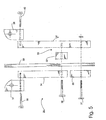
- FIG. 3 shows an application in which a second test lever 12 is attached to an elevator rope 13.
- a rope recording act two plates the elevator rope 13 between a first plate 14 and a second plate 15 is clamped.
- the clamping force is applied by screws 16 in this embodiment.
- a support 17 is mounted in the pivot point 18 of the test lever 12.
- the support 17 is fixed by means of a tension transmission element, in particular by means of a belt 19.
- a buckle-like Switzerlandübertragungselement recording 20 is provided on the support 17.
- FIG. 4 shows a sketchy representation of a fastening device 21 which is attached to a traction sheave 22.
- the traction sheave 22 is only partially shown.
- the fastening device 21 is clamped by means of a force-like device 23 to the traction sheave 22.
- the force-like device 23 consists of at least one clamp arm 24 and a screwable punch 25.
- the screwable punch 25 has a lever 26.
- a band 27 is attached on the fastening device.
- a buckle-like Buchauertragungselement recording 28 is used. This is angled in this embodiment of the remaining fastening device 21 in order to avoid contact of the Switzerlandübertragungsiatas, in this case the band 27, with an elevator rope or the traction sheave 22.
- FIG. 5 shows an exploded view of a support 29 (not part of the invention) of a special type, which can be attached to at least one uncontrolled elevator cable 30.
- An abutment 31 is connected to a step 32 and between the stepped abutment 33 and a first clamping plate 34 and a second clamping plate 35, the elevator cable 30 is clamped.
- the clamping forces are applied by means of screws 36, 37.
- the screws 36 also fasten the step 32 on the abutment 31.
- the support 29 strighebelagen 37, 38, where a test lever can be attached to a pivot point. In the embodiment shown here, the strighebelnessn are secured by means of screws 39, 40 on the bearing 29.
- Another embodiment provides a material connection, which either by welding or by a production of the clamping plate 34 and the strighebelage 35 and the abutment 31 and the exchebelage 38 is achieved from a workpiece.
- the receptacle 29 is attached to the elevator rope 30 so that a lift rope to be checked is freely movable, that is, that the elevator rope to be checked is not jammed between the clamping plates 34, 35 and the step-shaped abutment 33.
- This can be realized in one embodiment by a recess in the stage 32.
- the step 32 is in two parts and between the parts of the stage is to be checked elevator rope.
- Another embodiment provides for a one-piece step 32, adjacent to which runs the elevator rope to be checked.
- FIG. 6 shows a Buchauertragungselement-receptacle 41 for a chain 42.
- the chain 42 is attached by means of a snap hook 43 on Switzerlandzugungselement.
- a length change is achieved by attaching the snap hook to another link 44 of the chain 42.
- FIG. 7 shows a possible use of a test lever 45 (not part of the invention), wherein the test lever 45 is fixed by means of a support 46 at a fixed point 47.
- the fixed point 47 is in this example below support 46.
- a force 48 is therefore introduced into the power arm 49 of the test lever 45 directed upwards.
- a second force 50 consequently acts downward in an elevator rope 51 to which the test lever 45 is attached.
- the fixed point 47 may for example be part of an elevator installation.
- FIG. 8 shows a further possible use of the test lever 45 (not part of the invention), in which the support 46 is fixed to a fixed point 52. A force 53 is placed in the power arm 49 directed downwards. This results in an upward force 54, which is introduced into the elevator cable 51.
- FIG. 9 shows a particularly preferred use of the test lever according to the invention, in which the support 46 is attached via a pull transmission element 55 by means of a fastening element 56 to a traction sheave 57. Again, a force 58 is introduced into the power arm 49 from above and a resultant force 59 is introduced into the elevator cable 51.
Abstract
Description
Die Erfindung betrifft einen portablen Prüfhebel mit einem Last- und einem Kraftarm, einem variabel fixierbaren Auflager und einem Angelpunkt, der zwischen Last- und Kraftarm angeordnet ist, wobei der Prüfhebel sich über das Auflager abstützt, wenn eine Kraft auf den Prüfhebel aufgeprägt und auf mindestens ein zu überprüfendes Aufzugsseil zur Überprüfung einer Treibfähigkeit und/oder einer Seilbewegung mindestens des Aufzugsseils und/oder eines Beschleunigungsvermögens eines Aufzuges übertragen wird.The invention relates to a portable test lever with a load and a power arm, a variably fixable support and a pivot point which is arranged between the load and power arm, wherein the test lever is supported on the support when a force is applied to the test lever and at least an elevator rope to be checked is transmitted for checking a driving ability and / or a cable movement of at least the elevator cable and / or an acceleration capacity of an elevator.
Aus der
Zudem beschreibt die
Aufgabe der vorliegenden Erfindung ist eine Vorrichtung und ein Verfahren zur Verfügung zu stellen, bei dem ein Einrichten einer Prüfvorrichtung erst ermöglicht oder zumindest vereinfacht wird.It is an object of the present invention to provide an apparatus and a method in which setting up a test apparatus is made possible or at least simplified.
Die Aufgabe wird erfindungsgemäß gelöst durch einen portablen, insbesondere manuell betätigbaren Prüfhebel mit einem Last- und einem Kraftarm, einem variabel fixierbaren Auflager und einem Angelpunkt; der zwischen Last- und Kraftarm angeordnet ist, wobei der Prüfhebel sich über das Auflager abstützt, wenn eine Kraft auf den Prüfhebel aufgeprägt und auf mindestens ein zu überprüfendes Aufzugsseil zur Überprüfung einer Treibfähigkeit und/oder einer Seilbewegung mindestens des Aufzugsseils und/oder eines Beschleunigungsvermögens eines Aufzuges übertragen wird, wobei das variabel fixierbare Auflager in einem veränderlichen Abstand von einem Fixpunkt, der sich an einer Aufzugsanlage befindet, befestigbar ist. Die Befestigungsvorrichtung weist eine zwingenähnliche Vorrichtung zur kraftschlüssigen Befestigung eines Zugübertragungselements an einem Fixpunkt an einer Treibscheibe auf . Die Fixierung Ist mittels Befestigungselementen, vorzugsweise Schrauben oder Stempeln mit Gewinde, durchführbar. Die Befestigungselemente können in einer Ausgestaltung manuell, ohne Zuhilfenahme von Werkzeug ausreichend fest angezogen werden, um eine erforderliche Kraft für die Verbindung aufzubringen. Dies wird beispielsweise in einer Ausführung durch die Anbringung von vorzugsweise mindestens einem Hebel oder mittels eines einen Umfang eines Befestigungselementkopfes vergrößernden Rades oder Entsprechendem erreicht.The object is achieved by a portable, especially manually operable test lever with a load and a power arm, a variably fixable support and a pivot point; is arranged between the load and power arm, wherein the test lever is supported on the support when a force imparted to the test lever and at least one to be tested elevator rope to check a driving ability and / or a cable movement of at least the elevator cable and / or an acceleration capacity of Elevator is transferred, wherein the variably fixable support at a variable distance from a fixed point, which is located on an elevator system, can be fastened. The fastening device has a force-like device for the frictional attachment of a Zugübertragungselements at a fixed point on a traction sheave. The fixation is by means of fasteners, preferably screws or punches with thread feasible. The fasteners can be tightened sufficiently tight in one embodiment, without the aid of tools to apply a required force for the connection. This is for example in one Achieved by the attachment of preferably at least one lever or by means of a circumference of a fastener head enlarging wheel or equivalent.
Eine Aufzugsanlage soll hier definiert sein als ein Aufzug inklusive Aufzugskabine, Gegengewicht, Aufzugsseile, Treibscheibe, Antrieb und Befestigungsvorrichtungen für genannte Teile miteinander und mit der umgebenen Bebauung. Insbesondere kann der Fixpunkt an speziell einem dieser Bereiche der Aufzugsanlage angeordnet sein.An elevator installation should be defined here as an elevator including elevator car, counterweight, elevator ropes, traction sheave, drive and fastening devices for said parts with each other and with the surrounding buildings. In particular, the fixed point can be arranged on specifically one of these areas of the elevator installation.
Vorteil einer ersten Ausgestaltung ist es, daß die am Ort der Prüfung vorhandenen Objekte, vorzugsweise Aufzugsteile, genutzt werden können, um als Fixpunkt für das Auflager zu dienen. Die variable Fixierbarkeit des Auflagers ermöglicht auch bei unterschiedlichen Umgebungsvoraussetzungen eine schnelle und sichere Fixierung.Advantage of a first embodiment is that the existing at the site of the test objects, preferably elevator parts, can be used to serve as a fixed point for the support. The variable fixability of the support allows a fast and secure fixation even under different environmental conditions.
In einer zweiten Ausgestaltung ist an einem Ende des Lastarmes mindestens ein, vorzugsweise genau ein Aufzugsseil befestigbar. Der Lastarm ist ein Arm des Prüfhebels. Eine in den Kraftarm des Prüfhebels eingeleitete Kraft wird in das Aufzugsseil über den Lastarm impliziert. Durch Anordnung des Angelpunktes zwischen Kraft- und Lastarm ist die Kraft, die in das Aufzugsseil impliziert wird, der auf den Kraftarm auswirkenden Kraft entgegengesetzt.In a second embodiment, at least one, preferably exactly one elevator rope can be fastened to one end of the load arm. The load arm is an arm of the test lever. A force introduced into the power arm of the test lever is implied in the elevator rope via the load arm. By arranging the pivot between the load and load arms, the force implied in the elevator rope is opposed to the force acting on the force arm.
In einer weiteren Ausgestaltung ist das Auflager mittels mindestens einem Befestigungsmittel in dem Angelpunkt des portablen Prüfhebels fixiert. Das Befestigungselement kann beispielsweise ausgeführt sein als eine Schraube oder gemäß einer weiteren Ausführung als ein Bolzen oder ein Dorn, vorzugsweise mit einem Gewinde. Ein Verrutschen des Hebels im Auflager wird somit verhindert. Das Auflager ist in einer anderen Ausgestaltung mittels einer formschlüssigen Verbindung an dem Angelpunkt des portablen Prüfhebels befestigbar. Dies ermöglicht ein Einbringen einer durch das Hebelverhältnis definierten Kraft in das Aufzugsseil.In a further embodiment, the support is fixed by means of at least one fastening means in the hinge point of the portable test lever. The fastening element can be embodied, for example, as a screw or according to another embodiment as a bolt or a mandrel, preferably with a thread. Slipping of the lever in the support is thus prevented. The support can be fastened in another embodiment by means of a positive connection to the hinge point of the portable test lever. This allows introduction of a force defined by the lever ratio in the elevator rope.
Das Auflager ist gemäß einer Variante über ein Zugübertragungselement an dem Fixpunkt befestigbar. Das Zugübertragungselement kann beispielsweise ein Seil aufweisen. In einer weiteren Ausgestaltung weist das Zugübertragungselement ein Band auf, welches vorzugsweise aus textilem Material besteht. In einer besonderen Ausführung weist das Zugübertragungselement eine Kette auf. Auch kann das Zugübertragungselement gemäß einer Weiterbildung einen Stab beinhalten. Jedoch ist dann vorzugsweise eine entsprechende Vorkehrung zu treffen, damit das Zugübertragungselement einen variablen Abstand zum Fixpunkt ermöglichen kann. Vorzugsweise erfolgt dieses mittels einer Ausgestaltung als Teleskopstab.The support is fastened according to a variant via a train transmission element to the fixed point. The tension transmission element may, for example, comprise a cable. In a further embodiment, the tension transmission element has a band, which preferably consists of textile material. In a particular embodiment, the train transmission element has a chain. Also, the Zugübertragungselement according to a development include a rod. However, then an appropriate precaution is to be taken so that the tension transmission element can allow a variable distance to the fixed point. This is preferably done by means of a design as a telescopic rod.
In einer Ausführung wird das Auflager an dem Zugübertragungselement kraftschlüssig, bevorzugt reibschlüssig, befestigt. Unter einer kraftschlüssigen Verbindung ist eine Verbindung zu verstehen, bei der zwei Elemente so miteinander verbunden sind, daß ein erstes Element, oder Teile desselben, auf ein zweites Element eine Kraft aufbringt. Durch diese Kraft wird die Reibung zwischen den Elementen, oder Teilen derselben, so groß, daß eine Relativbewegung der Elemente zueinander verhindert wird. Eine solche Verbindung wird beispielsweise durch eine Schraube bzw. Schraubverbindung ermöglicht. Unter einer reibschlüssigen Verbindung ist eine Verbindung zu verstehen, bei der die Oberflächen zweier Elemente so miteinander in Kontakt stehen, daß aufgrund einer Reibung, die zwischen den Kontaktflächen auftritt, eine Relativbewegung zwischen den Elementen verhindert wird. Dies ist beispielsweise bei einer Klemmschnalle der Fall, aber auch ein Knoten erfüllt diese Eigenschaft. Des Weiteren ist in einer Weiterbildung das Zugübertragungselement an dem Fixpunkt mit einer kraftschlüssigen oder formschlüssigen Verbindung befestigbar. Die formschlüssige Verbindung ist beispielsweise eine in das Zugübertragungselement eingebrachte Schlaufe oder Öse, in welche ein entsprechendes Teil am Fixpunkt derartig eingreift, daß eine Relativbewegung von Zugübertragungselement zum Fixpunkt verhindert wird. Ebenso kann die formschlüssige Verbindung erreicht werden mittels eines Ringes und/oder eines Hakens, der am Fixpunkt befestigt ist. Um eine Verbindung des Zugübertragungselementes am Fixpunkt zu erreichen, weist eine weitere Ausführung eine Befestigungsvorrichtung am Zugübertragungselement auf.In one embodiment, the support is attached to the tension transmission element frictionally, preferably by friction. By a non-positive connection is meant a connection in which two elements are connected together such that a first element, or parts thereof, applies a force to a second element. By this force, the friction between the elements, or parts thereof, is so great that a relative movement of the elements is prevented from each other. Such a connection is made possible for example by a screw or screw connection. By a frictional connection is meant a connection in which the surfaces of two elements are in contact with each other such that a relative movement between the elements is prevented due to friction occurring between the contact surfaces. This is the case, for example, with a clamp buckle, but a node also fulfills this feature. Furthermore, in a development, the tension transmission element can be fastened to the fixed point with a frictional or positive connection. The positive connection is, for example, introduced into the train transmission element loop or eyelet into which a corresponding part of the fixed point engages such that a relative movement of Zugübertragungselement is prevented from the fixed point. Likewise, the positive connection can be achieved by means of a ring and / or a hook which is attached to the fixed point. In order to achieve a connection of the tension transmission element at the fixed point, another embodiment has a fastening device on the tension transmission element.
In einer besonders bevorzugten Ausführung des Prüfhebels weist das Auflager und/oder die Befestigungsvorrichtung eine Zugübertragungselement-Aufnahme auf. Diese kann beispielsweise mit mindestens zwei Schlitzen für eine schnallenartige Befestigung der Zugübertragungselementes ausgestaltet sein. Eine weitere Ausführung sieht mindestens zwei Aussparungen für eine seilklemmenartige Befestigung vor. Es ist auch eine Variante mit einer Aussparung möglich, mit der eine Kette beispielsweise mittels eines Karabinerhakens befestigt werden kann. Die Zugübertragungselement-Aufnahme ermöglicht ein schnelles und einfaches Befestigen des Zugübertragungselementes an einem Fixpunkt sowie ein schnelles und einfaches Variieren des Abstandes zwischen Fixpunkt und Aufnahme.In a particularly preferred embodiment of the test lever, the support and / or the fastening device has a Zugübertragungselement recording. This can be configured, for example, with at least two slots for a buckle-like fastening of the Zugübertragungselementes. Another embodiment provides at least two recesses for a rope clamp-like attachment. It is also a variant with a recess possible, with a chain can be attached, for example by means of a snap hook. The Zugübertragungselement recording allows a quick and easy attachment of the Zugübertragungselementes to a fixed point and a quick and easy variation of the distance between the fixing point and recording.
Gemäß einer Ausführung ist die Zugübertragungselement-Aufnahme an der Befestigungsvorrichtung abgewinkelt. Eine Ebene in der ein Winkel liegt wird definiert durch eine Ebene der Befestigungsvorrichtung. Vorzugsweise ist die Ebene der Befestigungsvorrichtung heranzuziehen, welche eine größte Schnittmenge mit der Befestigungsvorrichtung aufweist. Die Winkelebene ist senkrecht zu dieser und senkrecht zu einer Seitenfläche der Befestigungsvorrichtung. Der Winkel dreht sich aus der Ebene der Befestigungsvorrichtung heraus. Ein Winkel kann beispielsweise zwischen 10° und 90°, bevorzugt zwischen 20° und 55° betragen. In einer speziellen Ausgestaltung ist ein Winkel von 30° oder 45° zwischen der Zugübertragungselement-Aufnahme und der Ebene der Befestigungsvorrichtung vorgesehen. Toleranzen von etwa 10% sind möglich, bevorzugt sind Toleranzen kleiner 10%. Mit einem Winkel zwischen Zugübertragungselement-Aufnahme und Befestigungsvorrichtung ist ein Abstand des Zugübertragungselementes vom Fixpunkt, beispielsweise einer Treibscheibe, zu erreichen. In einer weiteren Ausführung ist der Winkel veränderbar. Zudem kann beispielsweise auch die Aufnahme eine abgewinkelte Zugübertragungselement-Aufnahme aufweisen, analog zur Zugübertragungselement-Aufnahme der Befestigungsvorrichtung und deren Ausführungen.According to one embodiment, the Zugübertragungselement recording is angled on the fastening device. A plane in which an angle lies is defined by a plane of the fastening device. Preferably, the plane of the fastening device is to be used, which has a largest intersection with the fastening device. The angle plane is perpendicular to this and perpendicular to a side surface of the fastening device. The angle turns out of the plane of the fastening device. An angle may for example be between 10 ° and 90 °, preferably between 20 ° and 55 °. In a specific embodiment, an angle of 30 ° or 45 ° is provided between the Zugübertragungselement- receiving and the plane of the fastening device. Tolerances of about 10% are possible, with tolerances of less than 10% being preferred. With an angle between Zugübertragungselement recording and fastening device is a distance of the Zugübertragungselementes from the fixed point, such as a traction sheave to reach. In a further embodiment, the angle is changeable. In addition, for example, the receptacle may have an angled Zugübertragungselement recording, analogous to Zugübertragungselement recording of the fastening device and their versions.
Damit ein Verdrehen der Befestigungsvorrichtung verhindert wird, kann die zwingenähnliche Vorrichtung mindestens zwei Befestigungselemente aufweisen. Die Befestigungselemente sind dann beispielsweise auf unterschiedlichen Längsachsen angeordnet, um einem auftretenden Moment entgegenzuwirken. Eine Kraft an beispielsweise der Zugübertragungselement-Aufnahme, welche ein erstes Moment erzeugt, wird an dem zweiten Befestigungspunkt eine Reaktionskraft erzeugen, die ein zweites Moment erzeugt. Da die beiden Momente entgegengesetzt gleich sind, wird eine Rotation der Befestigungsvorrichtung verhindert.In order to prevent twisting of the fastening device, the force-like device may have at least two fastening elements. The fastening elements are then arranged, for example, on different longitudinal axes in order to counteract an occurring moment. For example, a force on the traction transfer member receiver that generates a first moment will generate a reaction force at the second attachment point that generates a second moment. Since the two moments are opposite, a rotation of the fastening device is prevented.
In einer weiteren Ausführung ist der Prüfhebel mit einem Seilbewegungsindikator gekoppelt, bevorzugt weist die Befestigungsvorrichtung den Seilbewegungsindikator auf. Dieser kann beispielsweise Daten aufnehmen und/oder ausgeben, die beispielsweise für die Auswertung der Messung herangezogen werden können. Die Daten können über eine Messung gewonnen werden, die der Seitbewegungsindikator ausführt. Vorzugsweise kann die Bewegung und/oder Beschleunigung des Seiles gemessen werden. Die Daten können weiterverarbeitet werden. Dafür kann der Prüfhebel selbst oder eine mit diesem verbundene Auswerteeinheit entsprechende Programme hinterlegt aufweisen.In a further embodiment, the test lever is coupled to a rope movement indicator, the attachment device preferably has the rope movement indicator. This can, for example, record and / or output data that can be used, for example, for the evaluation of the measurement. The data can be obtained from a measurement performed by the lateral motion indicator. Preferably, the movement and / or acceleration of the rope can be measured. The data can be processed further. For this purpose, the test lever itself or a program associated with this evaluation corresponding programs have deposited.
In einer weiteren Variante weist die Befestigungsvorrichtung eine Indikatoröffnung auf. Die Indikatoröffnung ermöglicht beispielsweise die visuelle Überprüfung einer Seilbewegung. Des weiteren kann eine automatische Überprüfung erfolgen,'insbesondere kann die Indikatoröffnung dazu den Seilbewegungsindikator aufweisen.In a further variant, the fastening device has an indicator opening. The indicator opening allows, for example, the visual inspection of a cable movement. Furthermore, an automatic check can take place, in particular the indicator opening can have the cable movement indicator for this purpose.
In einer bevorzugten Ausgestaltung weist das variabel fixierbare Auflager eine Platte auf. Die Platte kann in einer Ausführung mit einer Aussparung versehen sein, in die der Prüfhebel eingeführt und fixiert werden kann. Zudem kann, gemäß einer weiteren Weiterbildung, in die Platte eine Zugübertragungselement-Aufnahme integriert werden.In a preferred embodiment, the variably fixable support has a plate. The plate may be provided in one embodiment with a recess into which the test lever can be inserted and fixed. In addition, according to a further development, in the plate a Zugübertragungselement recording are integrated.
In einer weiteren bevorzugten Variante umfaßt das Zugübertragungselement mindestens ein nicht zu prüfendes Aufzugsseil, das benachbart zum prüfenden Aufzugsseil angeordnet ist. Beispielsweise kann bei einer weiteren Ausführung das Auflager mittels einer Klemmverbindung am Zugübertragungselement bzw. am nicht zu prüfenden Aufzugsseil befestigt sein. Die benötigte Klemmkraft kann durch Befestigungselemente, vorzugsweise Schrauben, aufgebracht werden. In einer weiteren Ausgestaltung sind die Befestigungselemente Schnellspanner, die ohne Werkzeug derart befestigt werden können, daß sie die benötigte Klemmkraft aufbringen. Gemäß einer weiteren Variante kann das Zugübertragungselement über ein, zwei oder mehr Klemmplatten auf ein stufenförmiges Widerlager gepresst werden. Klemmplatten sind in diesem Fall Platten, welche die von den Befestigungselementen aufgebrachte Kraft auf ein oder mehrere nicht zu prüfende Aufzugsseile übertragen. Das stufenförmige Widerlager ist beispielsweise so gestaltet, daß die zu klemmenden Aufzugsseile über eine Stufe gepresst werden, um diese zu verkanten. Für das zu prüfende Aufzugsseil ist gemäß einer Ausführung vorgesehen, eine bevorzugt veränderliche Aussparung in der Stufe anzuordnen, um eine weitgehend reibungsfreie Bewegung des zu prüfenden Aufzugsseiles zu gewährleisten.In a further preferred variant, the tension transmission element comprises at least one elevator rope which is not to be tested and which is arranged adjacent to the test elevator rope. For example, in a further embodiment, the support can be fastened by means of a clamping connection on the tension transmission element or on the elevator rope which is not to be tested. The required clamping force can be applied by fastening elements, preferably screws. In a further embodiment, the fasteners are quick release, which can be fixed without tools such that they apply the required clamping force. According to a further variant, the tension transmission element can be pressed on one, two or more clamping plates on a stepped abutment. Clamping plates in this case are plates which transmit the force applied by the fastening elements to one or more elevator cables which are not to be tested. The stepped abutment is for example designed so that the elevator cables to be clamped are pressed over a step in order to tilt them. According to an embodiment, it is provided for the elevator rope to be tested to arrange a preferably variable recess in the step in order to ensure a largely friction-free movement of the elevator cable to be tested.
Gemäß einem weiteren Gedanken der Erfindung wird ein Verfahren zur Anbringung eines portablen Prüfhebels und zur Feststellung der Treibfähigkeit, einer Seilbewegung und/oder des Beschleunigungsvermögens eines Aufzuges mit folgenden, in der Reihenfolge veränderlichen Schritten vorgeschlagen:
- Befestigen eines Auflagers in einem Angelpunkt des Prüfhebels, so daß das Auflager zwischen einem Last- und einem Kraftarm liegt;
- Befestigen des Auflagers mittels eines Fixierungselements, vorzugsweise mit einer Befestigungsvorrichtung, an einem Fixpunkt oberhalb des Angelpunktes des Prüfhebels, vorzugsweise an einer Treibscheibe;
- Befestigen des Lastarmes des Prüfhebels an einem zu prüfenden Aufzugsseil;
- Einbringen einer nach unten gerichteten Kraft in den Kraftarm des Prüfhebels, wobei eine zweite Kraft in das zu prüfende Seil eingeleitet wird, die in entgegengesetzte Richtung zu der in den Kraftarm eingeleiteten Kraft wirkt;
- Aufnehmen mindestens eines, einen Zustand des Aufzugs charakterisierenden Meßparameters;
- Auswertung des Meßparameters bezüglich Treibfähigkeit, Seilbewegung und/oder Beschleunigungsvermögens des Aufzuges.
- Securing a support to a pivot point of the test lever so that the support is between a load and a power arm;
- Fixing the support by means of a fixing element, preferably with a fastening device, at a fixed point above the hinge point of the test lever, preferably on a traction sheave;
- Attaching the load arm of the test lever to an elevator rope to be tested;
- Inserting a downward force in the force arm of the test lever, wherein a second force is introduced into the rope to be tested, which acts in the opposite direction to the force introduced into the power arm;
- Receiving at least one measurement parameter characterizing a state of the elevator;
- Evaluation of the measuring parameter with regard to driving ability, rope movement and / or acceleration capacity of the elevator.
Der Fixpunkt kann gemäß einer Weiterbildung oberhalb des Angelpunktes des Prüfhebels gewährt werden. Eine in den Kraftarm des Prüfhebels eingeleitete Kraft kann nach unten gerichtet sein, wobei die zweite, in das Seil eingeleitete Kraft dann nach oben gerichtet ist.The fixed point can be granted according to a development above the pivot point of the test lever. A force introduced into the power arm of the test lever can be directed downwards, the second force introduced into the cable then being directed upwards.
Gemäß einer Variante kann der Fixpunkt unterhalb des Angelpunktes des Prüfhebels gewählt werden. Eine in den Kraftarm des Prüfhebels eingeleitete Kraft kann nach oben gerichtet sein, wobei die zweite, in das Seil eingeleitete Kraft darin nach unten gerichtet ist.According to a variant of the fixed point can be selected below the pivot point of the test lever. A force introduced into the power arm of the test lever may be directed upward, with the second force introduced into the cable directed downwardly therein.
Mindestens ein Meßparameter, der beispielsweise für die Auswertung beispielsweise der Treibfähigkeit, der Seilbewegung und/oder des Beschleunigungsvermögens herangezogen werden kann, wird in einer Ausbildung elektronisch aufgenommen, insbesondere mittels eines Seilbewegungsindikators. Gemäß einer Variante wird der Meßparameter an einen Empfänger übertragen. Insbesondere kann hierbei eine Übertragung mittels elektromagnetischer Strahlung erfolgen.At least one measurement parameter, which can be used, for example, for the evaluation of, for example, the drive capability, the cable movement and / or the acceleration capability, is recorded electronically in a design, in particular by means of a cable movement indicator. According to a variant, the measuring parameter is transmitted to a receiver. In particular, this can be done by means of electromagnetic radiation transmission.
In einer Ausführung wird mindestens ein Meßparameter und/oder ein Ergebnis vom Prüfhebel ausgegeben. Eine Ausgabe kann akustisch und/oder visuell erfolgen. In einer Weiterbildung kann die Ausgabe auch haptisch erfolgen, beispielsweise mittels eines Vibrators.In one embodiment, at least one measurement parameter and / or a result is output from the test lever. An output can be audible and / or visual. In a development, the output can also be haptic, for example by means of a vibrator.
Gemäß einer Variante kann die Auswertung des Meßparameters elektronisch erfolgen. In einer Ausgestaltung erfolgt die Auswertung im Prüfhebel. Hierzu kann beispielsweise ein Mikroprozessor, Signalprozessor oder ein Mikrocontroller verwendet werden, insbesondere am Prüfhebel und/oder an einer portablen Auswerteeinheit.According to a variant, the evaluation of the measurement parameter can be carried out electronically. In one embodiment, the evaluation is carried out in the test lever. For this purpose, for example, a microprocessor, signal processor or a microcontroller can be used, in particular on the test lever and / or on a portable evaluation unit.
Gemäß einer Ausbildung erfolgt eine quantitative und/oder qualitative Anzeige eines Meßparameters und/oder einer Auswertung.According to one embodiment, a quantitative and / or qualitative display of a measurement parameter and / or an evaluation takes place.
Die vorgenannten und weitere Vorteile werden anhand der folgenden dargestellten Figuren näher erläutert. Die in den Figuren gezeigten Merkmale sind jedoch nicht auf die einzelnen Ausgestaltungen beschränkt. Vielmehr sind die in der Figurenbeschreibung und Zeichnungen angegebenen Merkmale mit denen aus der obigen Beschreibung wie auch untereinander zu weiteren Ausgestaltungen miteinander verknüpfbar. Es zeigen im Einzelnen:
- Fig. 1:
- eine Ausgestaltung eines Prüfhebels,
- Fig. 2:
- eine Ausgestaltung eines Auflagers für einen Prüfhebel,
- Fig. 3:
- ein Anwendungsfall des Auflagers aus
Fig. 2 mit dem Prüfhebel, - Fig. 4:
- eine an einer Treibscheibe befestigte Befestigungsvorrichtung,
- Fig. 5:
- eine Explosionsskizze für ein Auflager, welches an nicht zu überprüfenden Aufzugsseilen befestigt wird (nicht Teil der Erfindung)
- Fig. 6:
- eine Ausführung einer Zugübertragungselement-Aufnahme,
- Fig. 7:
- eine Gestaltung einer Festpunktanordnung eines Prüfhebels (nicht Teil der Erfindung),
- Fig. 8:
- eine weitere Gestaltung einer Festpunktanordnung eines Prüfhebels (nicht Teil der Erfindung), und
- Fig. 9:
- eine Gestaltung einer Festpunktanordnung mittels einer Befestigungsvorrichtung an einer Treibscheibe.
- Fig. 1:
- an embodiment of a test lever,
- Fig. 2:
- an embodiment of a support for a test lever,
- 3:
- an application of the support
Fig. 2 with the test lever, - 4:
- a fastening device attached to a traction sheave,
- Fig. 5:
- an exploded view of a support which is attached to non-test elevator cables (not part of the invention)
- Fig. 6:
- an embodiment of a Zugübertragungselement recording,
- Fig. 7:
- a design of a fixed point arrangement of a test lever (not part of the invention),
- Fig. 8:
- a further design of a fixed point arrangement of a test lever (not part of the invention), and
- Fig. 9:
- a design of a fixed point arrangement by means of a fastening device to a traction sheave.
Der Prüfhebel 1 wird in der Aufnahme mittels einer Schraube 10 fixiert. Des weiteren befinden sich in der Platte zwei Schlitze 11, die eine Aufnahme für ein Zugübertragungselement bilden. Durch die Schlitze 11 wird beispielsweise ein Band gezogen, so daß sich eine schnallenartige Befestigung ergibt.The test lever 1 is fixed in the receptacle by means of a
Claims (19)
- A portable check lever (1; 12; 45) having a work arm (3) and a power arm (2; 49), a variably fixable support (7; 17; 46) and a fulcrum (18) arranged between the work arm (3) and the power arm (2; 49), wherein at least one lift cable (13; 51) to be checked can be secured to one end of the work arm (3) and wherein the check lever (1; 12; 45) is supported via the support (7; 17; 46) when a force (48; 53; 58) is exerted on the check lever (1; 12; 45) and transmitted onto the lift cable (19; 51) to check driving ability and/or cable motion of at least the lift cable (13; 51) and/or acceleration capacity of a lift, wherein the variably fixable support (7; 17; 46) can be secured at an alterable distance from a fixed point (47; 52) located an a lift installation, characterised in that a securing device (21) has a clamp-like device (23) for securing of a traction-transmitting element to the fixed point (47; 52) on a traction sheave (22; 57) in a non-positive locking manner, wherein fixing can be carried out by means of securing elements, preferably screws (25).
- A portable check lever (1; 12; 45) according to any one of the preceding claims, characterised in that a securing element (10) fixes the support (7; 17; 46) at the fulcrum (16) of the portable check lever (1; 12; 45).
- A portable check lever (1; 12; 45) according to any one of the previous claims, characterised in that the support (7; 17; 46) can be secured to the fixed point (47; 52) via a traction-transmitting element (19; 27).
- A portable check lever (1; 12; 45) according to any one of the preceding claims, characterised in that the check lever (1; 12; 45) has a securing device (21) to connect the traction-transmitting element (19; 27) to the fixed paint (47; 52).
- A portable check lever (1, 12; 45) according to any one of the preceding claims, characterised in that the support (7; 17; 46) and/or the securing device (21) connecting the traction-transmitting element (99; 27) to the fixed point (47; 52) has a traction-transmitting-element receiver (28; 41) which has at least two slots (11) for a buckle-like securing of a band, preferably of textile material, or at least two cut-outs for a cable-clamp-like securing of a cable, or at least one cut-out for securing a chain, for example by means of a snap hook (43).
- A portable check lever (1; 12; 45) according to claim 8, characterised in that the traction-transmitting-element receiver (28; 41) of the securing device (21) is angled, preferably between 10° and 90°.
- A portable check lever (1; 12; 45) according to claim 10, characterised in that the clamp-like device (23) has at least two securing elements, wherein the securing elements are arranged in such a manner that these have different longitudinal axes in order to counteract a moment.
- A portable check lever (1; 12; 45) according to any one of the preceding claims, characterised in that it is coupled to a cable-motion indicator or has the cable-motion indicator.
- A portable check lever (1; 12; 45) according to any one of the preceding claims, characterised in that the securing device (21) has an indicator opening (60).
- A portable check lever (1; 12; 45) according to any one of the preceding claims, characterised in that the indicator opening (60) has at least the cable-motion indicator.
- A portable check lever (1; 12; 45) according to any one of the preceding claims, characterised in that the variably fixable support (7; 17; 46) is a plate (8) having a cut-out (9) to receive the check lever (1; 12; 45) and/or a traction-transmitting-element receiver.
- A portable check lever (1; 12; 45) according to any one of the preceding claims, characterised in that the traction-transmitting element (19; 27) comprises at least one lift cable (30) which is not to be checked and which is adjacent to the lift cable (13) to be checked.
- A portable check lever (1; 12; 45) according to claim 12, characterised in that a clamping connection to secure the support to the traction-transmitting element is provided, by means of which a clamping force can be applied by means of securing elements, preferably screws (36, 37), and the traction-transmitting element can be pressed onto a step-shaped abutment (33) via at least two clamping plates (34, 35).
- A method of attaching a portable check lever (1; 12; 45) according to claim 1 and of ascertaining the driving ability, the cable motion and/or the acceleration capacity of a lift, having the following steps:- securing of a support (7; 17; 46) at a fulcrum (18) of the check lever (1; 12; 45), so that the support (7; 17; 46) lies between a work arm (3) and a power arm (2; 49);- securing of the support (7; 17; 46) via a fixing element (19; 27), preferably with a securing device (21), to a fixed point (47; 52) above the fulcrum (18) of the check lever (1; 12; 45), on a traction sheave (22);- securing of the work arm (3) of the check lever (1; 12; 45) to a lift cable (13; 51) to be checked;- introduction of a downwardly-directed force (53; 58) into the power arm (2; 49) of the check lever (1; 12; 45), wherein a force (50; 54; 59), acting in an opposite direction to the force (48; 53; 58) introduced into the power arm (2; 49), is introduced into the cable (13; 51) to be checked;- receiving of at least one measured parameter characterising a state of the lift;- evaluation of the measured parameter with regard to driving ability, cable motion and/or acceleration capacity of the lift.
- A method according to claim 14, characterised in that at least one measured parameter is received by means of a cable-motion indicator.
- A method according to any one of claims 13 to 15, characterised in that at least one measured parameter is received electronically.
- A method according to any one of claims 13 to 16, characterised in that at least one measured parameter is emitted visually and/or acoustically by the check lever (1; 12; 45).
- A method according to any one of claims 13 to 17, characterised in that an electronic evaluation of the at least one measured parameter and/or a qualitative and/or quantitative notification of at least one measured parameter takes place.
- A method according to claim 18, characterised in that the evaluation takes place in the check lever (1; 12; 45).
Applications Claiming Priority (1)
| Application Number | Priority Date | Filing Date | Title |
|---|---|---|---|
| DE102006011092A DE102006011092A1 (en) | 2006-03-08 | 2006-03-08 | Test lever with support |
Publications (3)
| Publication Number | Publication Date |
|---|---|
| EP1832541A1 EP1832541A1 (en) | 2007-09-12 |
| EP1832541A8 EP1832541A8 (en) | 2007-10-24 |
| EP1832541B1 true EP1832541B1 (en) | 2010-11-17 |
Family
ID=38069233
Family Applications (1)
| Application Number | Title | Priority Date | Filing Date |
|---|---|---|---|
| EP07004762A Active EP1832541B1 (en) | 2006-03-08 | 2007-03-08 | Check lever with bearing |
Country Status (3)
| Country | Link |
|---|---|
| EP (1) | EP1832541B1 (en) |
| AT (1) | ATE488465T1 (en) |
| DE (2) | DE102006011092A1 (en) |
Families Citing this family (6)
| Publication number | Priority date | Publication date | Assignee | Title |
|---|---|---|---|---|
| DE102006050570B4 (en) * | 2006-10-26 | 2016-08-18 | TÜV Rheinland Industrie Service GmbH | test lever |
| DE102008051292A1 (en) | 2008-10-10 | 2010-05-12 | TÜV Rheinland Industrie Service GmbH | Method for determining e.g. operating parameter of lift system, involves exciting part of traction rope to oscillation, and detecting generated oscillation at rope, where rope is guided over traction drive |
| DE102009038497A1 (en) | 2009-08-21 | 2011-02-24 | TÜV Rheinland Industrie Service GmbH | Method for determining traction characteristic of traction-sheave lift, involves measuring load acting on drive cable by using measuring device, and providing information about characteristic of lift system by determined load |
| DE102009038498A1 (en) | 2009-08-21 | 2011-02-24 | TÜV Rheinland Industrie Service GmbH | Method for determining state variables of lift system, involves applying force on force arm of test lever, where force arm of test lever compensates weights over lever force of test lever while measuring weights |
| DE102010024829B4 (en) | 2010-06-23 | 2019-08-14 | TÜV Rheinland Industrie Service GmbH | Method for determining a traction capability of an elevator installation and monitoring device |
| CN109969908A (en) * | 2019-03-18 | 2019-07-05 | 北京市环宇电梯工程有限公司 | A kind of the hoist cable fracture of wire check device and inspection method of elevator |
Family Cites Families (9)
| Publication number | Priority date | Publication date | Assignee | Title |
|---|---|---|---|---|
| DE605092C (en) * | 1932-08-18 | 1934-11-03 | Richard Schulte Fa | Device for testing safety gears |
| DE3911391C5 (en) * | 1989-04-07 | 2010-04-29 | TÜV SÜD Industrie Service GmbH | Method and device for checking the driving ability |
| DE8904375U1 (en) * | 1989-04-07 | 1989-07-27 | Tuev Bayern E.V., 8000 Muenchen, De | |
| DE9015495U1 (en) * | 1990-11-12 | 1992-01-02 | Technischer Ueberwachungs-Verein Bayern E.V., 8000 Muenchen, De | |
| DE4201840A1 (en) * | 1992-01-24 | 1993-07-29 | Rhein Westfael Tech Ueberwach | Method for testing drive-efficiency of pull-devices - has mobile basket locked against motion and movable weight mounted on lever for moment measurements at position of disc slip. |
| DE4311011C2 (en) * | 1992-07-24 | 1994-07-14 | Arno John | Method and device for testing an elevator with a traction sheave drive |
| DE10323175A1 (en) * | 2003-05-22 | 2004-12-23 | TÜV Industrie Service GmbH - TÜV Rheinland Group | test lever |
| DE102004029133A1 (en) * | 2004-06-17 | 2006-01-05 | TÜV Industrie Service GmbH - TÜV Rheinland Group | Force-reduced measuring method for traction drives, in particular traction sheave drives of elevators |
| DE102005010346A1 (en) * | 2005-03-07 | 2006-09-14 | TÜV Rheinland Industrie Service GmbH | Test device and associated method |
-
2006
- 2006-03-08 DE DE102006011092A patent/DE102006011092A1/en not_active Withdrawn
-
2007
- 2007-03-08 EP EP07004762A patent/EP1832541B1/en active Active
- 2007-03-08 AT AT07004762T patent/ATE488465T1/en active
- 2007-03-08 DE DE502007005640T patent/DE502007005640D1/en active Active
Also Published As
| Publication number | Publication date |
|---|---|
| DE502007005640D1 (en) | 2010-12-30 |
| EP1832541A8 (en) | 2007-10-24 |
| ATE488465T1 (en) | 2010-12-15 |
| EP1832541A1 (en) | 2007-09-12 |
| DE102006011092A1 (en) | 2007-09-13 |
Similar Documents
| Publication | Publication Date | Title |
|---|---|---|
| EP1832541B1 (en) | Check lever with bearing | |
| DE3911391A1 (en) | METHOD FOR DETECTING THE PHYSICAL CHARACTERISTICS OF AN ELEVATOR | |
| EP0182013B1 (en) | Means for fastening of a first structural member | |
| EP1755998B1 (en) | Force-reduced measuring method for traction drives, particularly friction pulley drives for elevators | |
| DE10248298A1 (en) | Rivet placing tool with monitoring of parameters of pulling device acting on rivet bolt gripping device for monitoring riveting process | |
| EP1700810B1 (en) | Checking device and method | |
| EP1847501A2 (en) | Lift installation with a surveillance device of the load carrier for monitoring the status of the load carrier and method for testing the load carrier | |
| EP1628900B1 (en) | Test lever | |
| EP2393746B1 (en) | Device for carrying out a load test in a lift assembly and method for carrying out such a test | |
| EP2496508B1 (en) | Method and device for testing the tensile strength in pulling elements of a pulling element line | |
| EP0902266B1 (en) | Device for measuring the tension in a belt, in particular a lashing strap | |
| WO2019185695A1 (en) | Method and device for monitoring properties of a supporting-means arrangement in a lift system | |
| DE112017005033B4 (en) | Tension test tool for lashing | |
| DE202006015829U1 (en) | Traction measuring device used in lifting or dragging mechanisms with e.g. chains, ropes, has measuring unit with lateral opening for permitting passage of pulling device in measuring unit which is formed with partly embraced side sections | |
| EP3838825B1 (en) | Extension sensor for a position measuring belt of an elevator | |
| DE102006050570A1 (en) | Test lever system for use in elevator, comprises test lever with force arm and load arm for determining of different variables of elevator system | |
| DE102004020440B3 (en) | Testing device for quality control of a cable and suitable test method | |
| DE112019005164B4 (en) | Sensor mounting element for roll guidance device | |
| DE102020202926B4 (en) | Belt conveyor for a trolley of a cross belt sorter | |
| DE19941005A1 (en) | Belt force measurement arrangement has belt holders on either side of force measurement element bearer and connected to it to hold belt on either side of bearer, belt attachment devices | |
| EP3764075B1 (en) | Device for measuring a force in the displacement direction of a footboard of a railway vehicle slidable in the displacement direction | |
| DE102022101998A1 (en) | ADAPTER FOR CABLE TIE PLIERS | |
| EP3441726A1 (en) | Method for detachably fastening clamp-on ultrasound flow rate sensors and apparatus for same and a clamping unit | |
| DE19712907C1 (en) | Method for installing a belt tensioning device having an eccentric arrangement on an internal combustion engine and device for carrying out this method | |
| WO2015062958A1 (en) | Device for testing and adjusting load-bearing means tension in a load-bearing means line |
Legal Events
| Date | Code | Title | Description |
|---|---|---|---|
| PUAI | Public reference made under article 153(3) epc to a published international application that has entered the european phase |
Free format text: ORIGINAL CODE: 0009012 |
|
| 17P | Request for examination filed |
Effective date: 20070308 |
|
| AK | Designated contracting states |
Kind code of ref document: A1 Designated state(s): AT BE BG CH CY CZ DE DK EE ES FI FR GB GR HU IE IS IT LI LT LU LV MC MT NL PL PT RO SE SI SK TR |
|
| AX | Request for extension of the european patent |
Extension state: AL BA HR MK YU |
|
| RTI1 | Title (correction) |
Free format text: CHECK LEVER WITH BEARING |
|
| 17Q | First examination report despatched |
Effective date: 20071214 |
|
| AKX | Designation fees paid |
Designated state(s): AT BE BG CH CY CZ DE DK EE ES FI FR GB GR HU IE IS IT LI LT LU LV MC MT NL PL PT RO SE SI SK TR |
|
| AXX | Extension fees paid |
Extension state: BA Payment date: 20070308 Extension state: HR Payment date: 20070308 Extension state: AL Payment date: 20070308 Extension state: MK Payment date: 20070308 Extension state: RS Payment date: 20070308 |
|
| GRAP | Despatch of communication of intention to grant a patent |
Free format text: ORIGINAL CODE: EPIDOSNIGR1 |
|
| GRAC | Information related to communication of intention to grant a patent modified |
Free format text: ORIGINAL CODE: EPIDOSCIGR1 |
|
| GRAS | Grant fee paid |
Free format text: ORIGINAL CODE: EPIDOSNIGR3 |
|
| GRAA | (expected) grant |
Free format text: ORIGINAL CODE: 0009210 |
|
| AK | Designated contracting states |
Kind code of ref document: B1 Designated state(s): AT BE BG CH CY CZ DE DK EE ES FI FR GB GR HU IE IS IT LI LT LU LV MC MT NL PL PT RO SE SI SK TR |
|
| AX | Request for extension of the european patent |
Extension state: AL BA HR MK RS |
|
| REG | Reference to a national code |
Ref country code: GB Ref legal event code: FG4D Free format text: NOT ENGLISH |
|
| REG | Reference to a national code |
Ref country code: CH Ref legal event code: EP |
|
| REG | Reference to a national code |
Ref country code: IE Ref legal event code: FG4D |
|
| REF | Corresponds to: |
Ref document number: 502007005640 Country of ref document: DE Date of ref document: 20101230 Kind code of ref document: P |
|
| REG | Reference to a national code |
Ref country code: NL Ref legal event code: VDEP Effective date: 20101117 |
|
| LTIE | Lt: invalidation of european patent or patent extension |
Effective date: 20101117 |
|
| PG25 | Lapsed in a contracting state [announced via postgrant information from national office to epo] |
Ref country code: LT Free format text: LAPSE BECAUSE OF FAILURE TO SUBMIT A TRANSLATION OF THE DESCRIPTION OR TO PAY THE FEE WITHIN THE PRESCRIBED TIME-LIMIT Effective date: 20101117 |
|
| PG25 | Lapsed in a contracting state [announced via postgrant information from national office to epo] |
Ref country code: LV Free format text: LAPSE BECAUSE OF FAILURE TO SUBMIT A TRANSLATION OF THE DESCRIPTION OR TO PAY THE FEE WITHIN THE PRESCRIBED TIME-LIMIT Effective date: 20101117 Ref country code: FI Free format text: LAPSE BECAUSE OF FAILURE TO SUBMIT A TRANSLATION OF THE DESCRIPTION OR TO PAY THE FEE WITHIN THE PRESCRIBED TIME-LIMIT Effective date: 20101117 Ref country code: IS Free format text: LAPSE BECAUSE OF FAILURE TO SUBMIT A TRANSLATION OF THE DESCRIPTION OR TO PAY THE FEE WITHIN THE PRESCRIBED TIME-LIMIT Effective date: 20110317 Ref country code: PT Free format text: LAPSE BECAUSE OF FAILURE TO SUBMIT A TRANSLATION OF THE DESCRIPTION OR TO PAY THE FEE WITHIN THE PRESCRIBED TIME-LIMIT Effective date: 20110317 Ref country code: SE Free format text: LAPSE BECAUSE OF FAILURE TO SUBMIT A TRANSLATION OF THE DESCRIPTION OR TO PAY THE FEE WITHIN THE PRESCRIBED TIME-LIMIT Effective date: 20101117 Ref country code: NL Free format text: LAPSE BECAUSE OF FAILURE TO SUBMIT A TRANSLATION OF THE DESCRIPTION OR TO PAY THE FEE WITHIN THE PRESCRIBED TIME-LIMIT Effective date: 20101117 Ref country code: CY Free format text: LAPSE BECAUSE OF FAILURE TO SUBMIT A TRANSLATION OF THE DESCRIPTION OR TO PAY THE FEE WITHIN THE PRESCRIBED TIME-LIMIT Effective date: 20101117 Ref country code: SI Free format text: LAPSE BECAUSE OF FAILURE TO SUBMIT A TRANSLATION OF THE DESCRIPTION OR TO PAY THE FEE WITHIN THE PRESCRIBED TIME-LIMIT Effective date: 20101117 Ref country code: BG Free format text: LAPSE BECAUSE OF FAILURE TO SUBMIT A TRANSLATION OF THE DESCRIPTION OR TO PAY THE FEE WITHIN THE PRESCRIBED TIME-LIMIT Effective date: 20110217 |
|
| REG | Reference to a national code |
Ref country code: IE Ref legal event code: FD4D |
|
| PG25 | Lapsed in a contracting state [announced via postgrant information from national office to epo] |
Ref country code: GR Free format text: LAPSE BECAUSE OF FAILURE TO SUBMIT A TRANSLATION OF THE DESCRIPTION OR TO PAY THE FEE WITHIN THE PRESCRIBED TIME-LIMIT Effective date: 20110218 |
|
| PG25 | Lapsed in a contracting state [announced via postgrant information from national office to epo] |
Ref country code: CZ Free format text: LAPSE BECAUSE OF FAILURE TO SUBMIT A TRANSLATION OF THE DESCRIPTION OR TO PAY THE FEE WITHIN THE PRESCRIBED TIME-LIMIT Effective date: 20101117 Ref country code: EE Free format text: LAPSE BECAUSE OF FAILURE TO SUBMIT A TRANSLATION OF THE DESCRIPTION OR TO PAY THE FEE WITHIN THE PRESCRIBED TIME-LIMIT Effective date: 20101117 Ref country code: ES Free format text: LAPSE BECAUSE OF FAILURE TO SUBMIT A TRANSLATION OF THE DESCRIPTION OR TO PAY THE FEE WITHIN THE PRESCRIBED TIME-LIMIT Effective date: 20110228 Ref country code: IE Free format text: LAPSE BECAUSE OF FAILURE TO SUBMIT A TRANSLATION OF THE DESCRIPTION OR TO PAY THE FEE WITHIN THE PRESCRIBED TIME-LIMIT Effective date: 20101117 |
|
| PG25 | Lapsed in a contracting state [announced via postgrant information from national office to epo] |
Ref country code: DK Free format text: LAPSE BECAUSE OF FAILURE TO SUBMIT A TRANSLATION OF THE DESCRIPTION OR TO PAY THE FEE WITHIN THE PRESCRIBED TIME-LIMIT Effective date: 20101117 Ref country code: PL Free format text: LAPSE BECAUSE OF FAILURE TO SUBMIT A TRANSLATION OF THE DESCRIPTION OR TO PAY THE FEE WITHIN THE PRESCRIBED TIME-LIMIT Effective date: 20101117 Ref country code: SK Free format text: LAPSE BECAUSE OF FAILURE TO SUBMIT A TRANSLATION OF THE DESCRIPTION OR TO PAY THE FEE WITHIN THE PRESCRIBED TIME-LIMIT Effective date: 20101117 Ref country code: RO Free format text: LAPSE BECAUSE OF FAILURE TO SUBMIT A TRANSLATION OF THE DESCRIPTION OR TO PAY THE FEE WITHIN THE PRESCRIBED TIME-LIMIT Effective date: 20101117 |
|
| PLBE | No opposition filed within time limit |
Free format text: ORIGINAL CODE: 0009261 |
|
| STAA | Information on the status of an ep patent application or granted ep patent |
Free format text: STATUS: NO OPPOSITION FILED WITHIN TIME LIMIT |
|
| BERE | Be: lapsed |
Owner name: TUV RHEINLAND INDUSTRIE SERVICE G.M.B.H. Effective date: 20110331 |
|
| 26N | No opposition filed |
Effective date: 20110818 |
|
| PG25 | Lapsed in a contracting state [announced via postgrant information from national office to epo] |
Ref country code: MC Free format text: LAPSE BECAUSE OF NON-PAYMENT OF DUE FEES Effective date: 20110331 |
|
| REG | Reference to a national code |
Ref country code: CH Ref legal event code: PL |
|
| GBPC | Gb: european patent ceased through non-payment of renewal fee |
Effective date: 20110308 |
|
| REG | Reference to a national code |
Ref country code: DE Ref legal event code: R097 Ref document number: 502007005640 Country of ref document: DE Effective date: 20110818 |
|
| REG | Reference to a national code |
Ref country code: FR Ref legal event code: ST Effective date: 20111130 |
|
| PG25 | Lapsed in a contracting state [announced via postgrant information from national office to epo] |
Ref country code: MT Free format text: LAPSE BECAUSE OF FAILURE TO SUBMIT A TRANSLATION OF THE DESCRIPTION OR TO PAY THE FEE WITHIN THE PRESCRIBED TIME-LIMIT Effective date: 20101117 Ref country code: BE Free format text: LAPSE BECAUSE OF NON-PAYMENT OF DUE FEES Effective date: 20110331 Ref country code: IT Free format text: LAPSE BECAUSE OF FAILURE TO SUBMIT A TRANSLATION OF THE DESCRIPTION OR TO PAY THE FEE WITHIN THE PRESCRIBED TIME-LIMIT Effective date: 20101117 |
|
| PG25 | Lapsed in a contracting state [announced via postgrant information from national office to epo] |
Ref country code: FR Free format text: LAPSE BECAUSE OF NON-PAYMENT OF DUE FEES Effective date: 20110331 Ref country code: CH Free format text: LAPSE BECAUSE OF NON-PAYMENT OF DUE FEES Effective date: 20110331 Ref country code: LI Free format text: LAPSE BECAUSE OF NON-PAYMENT OF DUE FEES Effective date: 20110331 |
|
| PG25 | Lapsed in a contracting state [announced via postgrant information from national office to epo] |
Ref country code: GB Free format text: LAPSE BECAUSE OF NON-PAYMENT OF DUE FEES Effective date: 20110308 |
|
| REG | Reference to a national code |
Ref country code: AT Ref legal event code: MM01 Ref document number: 488465 Country of ref document: AT Kind code of ref document: T Effective date: 20120308 |
|
| PG25 | Lapsed in a contracting state [announced via postgrant information from national office to epo] |
Ref country code: LU Free format text: LAPSE BECAUSE OF NON-PAYMENT OF DUE FEES Effective date: 20110308 |
|
| PG25 | Lapsed in a contracting state [announced via postgrant information from national office to epo] |
Ref country code: AT Free format text: LAPSE BECAUSE OF NON-PAYMENT OF DUE FEES Effective date: 20120308 |
|
| PG25 | Lapsed in a contracting state [announced via postgrant information from national office to epo] |
Ref country code: TR Free format text: LAPSE BECAUSE OF FAILURE TO SUBMIT A TRANSLATION OF THE DESCRIPTION OR TO PAY THE FEE WITHIN THE PRESCRIBED TIME-LIMIT Effective date: 20101117 |
|
| PG25 | Lapsed in a contracting state [announced via postgrant information from national office to epo] |
Ref country code: HU Free format text: LAPSE BECAUSE OF FAILURE TO SUBMIT A TRANSLATION OF THE DESCRIPTION OR TO PAY THE FEE WITHIN THE PRESCRIBED TIME-LIMIT Effective date: 20101117 |
|
| REG | Reference to a national code |
Ref country code: DE Ref legal event code: R082 Ref document number: 502007005640 Country of ref document: DE Representative=s name: VON KREISLER SELTING WERNER - PARTNERSCHAFT VO, DE Ref country code: DE Ref legal event code: R082 Ref document number: 502007005640 Country of ref document: DE Representative=s name: DOMPATENT VON KREISLER SELTING WERNER - PARTNE, DE |
|
| PGFP | Annual fee paid to national office [announced via postgrant information from national office to epo] |
Ref country code: DE Payment date: 20230330 Year of fee payment: 17 |