EP1832437B1 - Vorrichtung für Bücher mit Doppelumschlagklappe - Google Patents
Vorrichtung für Bücher mit Doppelumschlagklappe Download PDFInfo
- Publication number
- EP1832437B1 EP1832437B1 EP06110940A EP06110940A EP1832437B1 EP 1832437 B1 EP1832437 B1 EP 1832437B1 EP 06110940 A EP06110940 A EP 06110940A EP 06110940 A EP06110940 A EP 06110940A EP 1832437 B1 EP1832437 B1 EP 1832437B1
- Authority
- EP
- European Patent Office
- Prior art keywords
- books
- trimming
- fore
- machine
- edge
- Prior art date
- Legal status (The legal status is an assumption and is not a legal conclusion. Google has not performed a legal analysis and makes no representation as to the accuracy of the status listed.)
- Expired - Lifetime
Links
Images


Classifications
-
- B—PERFORMING OPERATIONS; TRANSPORTING
- B26—HAND CUTTING TOOLS; CUTTING; SEVERING
- B26D—CUTTING; DETAILS COMMON TO MACHINES FOR PERFORATING, PUNCHING, CUTTING-OUT, STAMPING-OUT OR SEVERING
- B26D1/00—Cutting through work characterised by the nature or movement of the cutting member or particular materials not otherwise provided for; Apparatus or machines therefor; Cutting members therefor
- B26D1/01—Cutting through work characterised by the nature or movement of the cutting member or particular materials not otherwise provided for; Apparatus or machines therefor; Cutting members therefor involving a cutting member which does not travel with the work
- B26D1/04—Cutting through work characterised by the nature or movement of the cutting member or particular materials not otherwise provided for; Apparatus or machines therefor; Cutting members therefor involving a cutting member which does not travel with the work having a linearly-movable cutting member
- B26D1/06—Cutting through work characterised by the nature or movement of the cutting member or particular materials not otherwise provided for; Apparatus or machines therefor; Cutting members therefor involving a cutting member which does not travel with the work having a linearly-movable cutting member wherein the cutting member reciprocates
- B26D1/08—Cutting through work characterised by the nature or movement of the cutting member or particular materials not otherwise provided for; Apparatus or machines therefor; Cutting members therefor involving a cutting member which does not travel with the work having a linearly-movable cutting member wherein the cutting member reciprocates of the guillotine type
-
- B—PERFORMING OPERATIONS; TRANSPORTING
- B26—HAND CUTTING TOOLS; CUTTING; SEVERING
- B26D—CUTTING; DETAILS COMMON TO MACHINES FOR PERFORATING, PUNCHING, CUTTING-OUT, STAMPING-OUT OR SEVERING
- B26D7/00—Details of apparatus for cutting, cutting-out, stamping-out, punching, perforating, or severing by means other than cutting
- B26D7/01—Means for holding or positioning work
- B26D7/015—Means for holding or positioning work for sheet material or piles of sheets
-
- B—PERFORMING OPERATIONS; TRANSPORTING
- B42—BOOKBINDING; ALBUMS; FILES; SPECIAL PRINTED MATTER
- B42C—BOOKBINDING
- B42C11/00—Casing-in
- B42C11/02—Machines or equipment for casing-in or applying covers to pamphlets, magazines, pads, or other paper-covered booklets
-
- B—PERFORMING OPERATIONS; TRANSPORTING
- B42—BOOKBINDING; ALBUMS; FILES; SPECIAL PRINTED MATTER
- B42C—BOOKBINDING
- B42C11/00—Casing-in
- B42C11/04—Machines or equipment for casing-in or applying covers to books
-
- B—PERFORMING OPERATIONS; TRANSPORTING
- B42—BOOKBINDING; ALBUMS; FILES; SPECIAL PRINTED MATTER
- B42C—BOOKBINDING
- B42C5/00—Preparing the edges or backs of leaves or signatures for binding
- B42C5/02—Preparing the edges or backs of leaves or signatures for binding by rounding or backing
-
- B—PERFORMING OPERATIONS; TRANSPORTING
- B26—HAND CUTTING TOOLS; CUTTING; SEVERING
- B26D—CUTTING; DETAILS COMMON TO MACHINES FOR PERFORATING, PUNCHING, CUTTING-OUT, STAMPING-OUT OR SEVERING
- B26D7/00—Details of apparatus for cutting, cutting-out, stamping-out, punching, perforating, or severing by means other than cutting
-
- Y—GENERAL TAGGING OF NEW TECHNOLOGICAL DEVELOPMENTS; GENERAL TAGGING OF CROSS-SECTIONAL TECHNOLOGIES SPANNING OVER SEVERAL SECTIONS OF THE IPC; TECHNICAL SUBJECTS COVERED BY FORMER USPC CROSS-REFERENCE ART COLLECTIONS [XRACs] AND DIGESTS
- Y10—TECHNICAL SUBJECTS COVERED BY FORMER USPC
- Y10S—TECHNICAL SUBJECTS COVERED BY FORMER USPC CROSS-REFERENCE ART COLLECTIONS [XRACs] AND DIGESTS
- Y10S83/00—Cutting
- Y10S83/929—Particular nature of work or product
- Y10S83/934—Book, being made, e.g. trimming a signature
Definitions
- the present invention relates to a machine for trimming the fore-edge of books with a cover the two openable parts of which are provided at the book fore-edge with respective inwardly folded flaps.
- Another solution which has been used consists of adding to a normal production line an additional three knife trimmer in which only the blade for trimming the fore-edge of the book blocks is left (this additional three knife trimmer not being used for normal production), the fore-edge trimming blade being removed from the line three knife trimmer when books with a flapped cover are to be produced.
- This solution also involves a considerable additional cost as two three knife trimmers (without in this case three knives) have to be provided in the same line, of which the upstream trimmer operates only when flapped covers are to be produced.
- trimming machines with a single blade have been constructed, to be located, in contrast to previous machines, downstream of the perfect binder but in a by-pass of the normal production line. If books with a flapped cover are to be produced, these machines enable the spine of books with a flapped cover to be trimmed after sucker means open the two operable parts of the cover, with the relative flap, so that the spine trimming blade does not interfere with the flaps see for instance the document EP 1053890 and EP 0754566 . As these machines receive book blocks already provided with their cover (which gives consistency to the assembly of signatures, i.e. to the book block), these machines can be used both in the case of a sewn spine and in the case of a milled and glued spine.
- the trimming blade can be positioned horizontally or vertically. In this latter case the blade can be moved horizontally to adjust its position on the basis of the width of the book to be trimmed.
- the books move horizontally within the trimming machine on conveyor devices comprising two superposed belts the adjacent branches of which are parallel, the books arriving in succession between these branches with their fore-edge projecting from the belts.
- the elevation of the upper belt can be adjusted, while that of the lower belt is fixed.
- the books remain horizontal during trimming, the blade moving from the top downwards, to then rise again into its starting position.
- the machine Prior to trimming, when the two opposing openable parts of the cover have already been opened by the relative suckers, a presser is rested on the top of the book block close to the fore-edge, the corresponding bottom of the book block of signatures resting simultaneously on a fixed counter-presser on which, following trimming, scrap remains which has to be removed.
- the machine comprises blower means.
- An object of the present invention is to provide a machine for trimming the fore-edge of books to which the flapped cover has already been applied, without leaving marks on the cover in any case.
- Another object of the invention is therefore to provide a machine of the aforesaid type which also enables trimming of the fore-edge of books with a single-flap cover.
- the first said object is attained by the trimming machine of the present invention, of the type with a vertical fore-edge trimming blade, characterised by comprising two furrower means, one for each of the two faces of the book, each to be inserted, starting from the fore-edge, between the relative openable part of the cover and the book block to open this openable part before the trimming operation is carried out on the fore-edge, to prevent the blade from interfering with the cover.
- each furrower means there is provided a relative linear support element contained in a vertical plane parallel to the plane of the trimming blade, on the two support elements there directly resting the relative face of that part of the book block projecting from the cover before this latter comes into contact with the relative furrower means, to facilitate opening of the two openable parts of the cover by the relative furrower means.
- the trimming blade is movable within a fixed vertical plane, counteracting means being provided which act on the book fore-edge to be trimmed, said counteracting means being movable horizontally, perpendicularly to the blade, to move the book or books into a position, relative to the blade, which enables the required fore-edge portion to be removed following trimming.
- furrower means enables the respective openable part of the cover to be opened sufficiently to enable a presser and a counter-presser to be used having a width enabling the book block to be held rigidly during trimming, resulting in perfect trimming.
- furrower means are made removable, removing one of the two makes it possible to obtain books with a cover provided with only one flap, to hence also attain the second stated object.
- each conveyor device for the books the fore-edge of which is to be trimmed comprises a pair of superposed parallel belts (between which, as already stated, the books are placed with their spine parallel to but distant from the trimming blade) the relative upper belt having fixed elevation while the lower belt is movable vertically in the two directions to be able to adjust the distance between the two adjacent branches of the two belts on the basis of the thickness of the books the fore-edge of which is to be trimmed.
- an inclinable entry conveyor belt and an inclinable exit conveyor belt have to be provided to join said slide surface to the rest of the line.
- the counter-presser moves together with the lower belt, so that by adjusting the position of this latter the position of the counter-presser is also automatically adjusted.
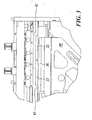
- the machine 10 for trimming the fore-edge of books already provided with a flapped cover comprises a structure indicated overall by 12.
- the structure 12 carries a first conveyor belt 14 connecting to the rest of the line and along which the books already provided with the flapped cover enter the machine 10 for trimming of their fore-edge.
- These books originate from a perfect binder positioned in the production line upstream of the machine 10. They either may or may not have been trimmed along the two parallel edges perpendicular to the spine.
- the fed books are presented as shown in Figure 6 , in which a book 22 comprises a book block 24 and a cover 23 provided with flaps 27 and 29.
- the book block 24 projects (by at least 3 mm) from that edge of the cover 23 provided with flaps, so requiring trimming of the fore-edge.
- the books to be trimmed (not shown for simplicity in Figure 1 ) are fed in regular succession to the right end of the conveyor belt 14 such that while they advance in the direction of the arrow A, their spine rests against a reference wall 16 with which the conveyor belt 14 is provided.
- the position of the reference wall 16 is adjustable in a direction perpendicular to itself by conventional mechanisms on depends on the width of the books the fore-edge of which is to be trimmed.
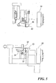
- a subsequent conveyor device 19 (best seen in Figures 4 and 5 ) comprising two superposed belts 18 and 20, mounted about relative pulleys, the adjacent branches of the two belts being parallel to each other at a distance apart enabling the books originating from the conveyor belt 14 to be received and conveyed between them.
- the distance between the two belts 18 and 20 is adjustable by conventional mechanisms which enable the lower belt 20 to be raised or lowered on the basis of the height of the books 22 to be trimmed, the fore-edge of these latter projecting from the belts 18, 20 (towards the left, with reference to Figure 6 ).
- the machine 10 is provided with a scrap adjustment means comprising a pusher 30 ( Figures 1 and 6 ) movable horizontally in the two directions (as indicated by the double arrow F of Figure 6 ) perpendicular to the direction of advancement of the books 22, by conventional mechanisms.
- a scrap adjustment means comprising a pusher 30 ( Figures 1 and 6 ) movable horizontally in the two directions (as indicated by the double arrow F of Figure 6 ) perpendicular to the direction of advancement of the books 22, by conventional mechanisms.
- the machine 10 also presents a lower linear support element 32, the upper edge of which is horizontal but is provided towards upstream with a lead-in bevel.
- the lower face of the book block 24 rests against the lower support element 32, as shown in Figure 6 .
- the furrower means Located downstream of the lower support 32 there is positioned the furrower means. This is an element, indicated by 34, shaped as a furrower and hereinafter known as the lower furrower.
- the purpose of this latter is to insert itself between the lower surface of the book block 24 and the folded flap 29 of the lower part 28 of the cover 23 such as to open this lower part 28 outwards (as shown in Figure 7 , in which however the furrower is not shown for simplicity) so that the in the subsequent trimming operation the blade (described hereinafter) does not interfere with the part 28.
- the lower linear support element 32 facilitates insertion of the lower furrower 34 between the lower face of the book block 24 and the relative openable part 28 of the cover 23.
- a presser 42 ( Figure 4 ) where it halts following the stoppage of the belts 18, 20.
- the presser 42 is movable vertically in the two directions (as indicated in Figure 7 by the double arrow C) to assume the position of Figure 7 , i.e. to press against the upper face of the book block 24.
- a counter-presser 43 is also present positioned to the side of the trimming blade 36 and of which the elevation is the same as the upper face of the upper branch of the lower belt 20.
- the counter-presser 43 moves vertically rigid with the lower belt 20, so that when the elevation of this latter is adjusted, the elevation of the counter-presser 43 is automatically adjusted.
- the trimming blade 36 is carried by a blade holder 44 which, by means of a connecting rod-crank mechanism (indicated overall by 46), is able to cause the blade 36 to undergo not only a vertical movement in the two directions but also a horizontal translation in the plane in which it lies, so that in practice the blade 36 moves within the vertical plane in a direction inclined at 45° to the horizontal, this facilitating the trimming operation.
- a connecting rod-crank mechanism indicated overall by 46
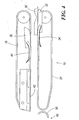
- the illustrated machine 10 also comprises in reality a second conveyor device 49 of belt type, which comprises belts 48 and 50 and is positioned just downstream of that comprising the belts 18, 20.
- a second conveyor device 49 of belt type which comprises belts 48 and 50 and is positioned just downstream of that comprising the belts 18, 20.
- the presser 42 and counter-presser 43 have a horizontal length involving both the pairs of belts 18, 20 and 48, 50.
- the presser 42 When the trimming operation has been carried out, the presser 42 returns to its raised starting position ( Figure 2 ) so that, on operating the two pairs of belts 18, 20 and 48, 50, the two simultaneously trimmed books 22 can be fed to the subsequent processes in the line of which the trimming machine 10 forms part.
- the machine 10 also comprises an exit conveyor belt 52 with relative reference wall 54, for connection to the remaining part of the line.
- the exit conveyor belt 52 As the elevation of the resting surface for the books 22 during the trimming operation depends on the book thickness, the exit conveyor belt 52, also carried by the structure 12, is inclinable (as is the feed conveyor 14) for its connection to the downstream part of the production line.
- the machine 10 is positioned downstream of the perfect binder and receives books 22 already provided with their cover 23, so that it is able to trim the fore-edge both of books with a sewn spine and of books with a milled and glued spine.
- the machine 10 is structured to be able to occupy downstream of the perfect binder that position which in a normal production line is occupied by a portion of the connecting conveyor belt, so that it is not necessary to change the line layout. If the fore-edge of books with a flapless cover is to be trimmed, the reference walls 16 and 54 of the feed conveyor belt 14 and exit conveyor belt 52 have merely to be adjusted so that the books 22 do not interfere with the furrowers 34 and 40, so that the machine 10 (the cutting function of which has been deactivated) acts as a simple connection conveyor device.
Landscapes
- Engineering & Computer Science (AREA)
- Mechanical Engineering (AREA)
- Forests & Forestry (AREA)
- Life Sciences & Earth Sciences (AREA)
- Soil Working Implements (AREA)
- Treatment Of Fiber Materials (AREA)
- Folding Of Thin Sheet-Like Materials, Special Discharging Devices, And Others (AREA)
- Harvester Elements (AREA)
- Nonmetal Cutting Devices (AREA)
- Sewing Machines And Sewing (AREA)
- Closing Of Containers (AREA)
- Container Filling Or Packaging Operations (AREA)
- Structure Of Belt Conveyors (AREA)
- Sheet Holders (AREA)
- Control And Other Processes For Unpacking Of Materials (AREA)
- Cleaning In General (AREA)
- Apparatuses For Bulk Treatment Of Fruits And Vegetables And Apparatuses For Preparing Feeds (AREA)
Claims (9)
- Maschine (10) zum Beschneiden der Vorderkante von Büchern (22), welche mit einem Buchblock (24), dessen Buchrücken entweder geheftet oder abgefräst und geleimt ist, und mit einem flexiblen Einband (23), dessen zu öffnende Teile (26, 28) entsprechend nach innen gefaltete Klappen (27, 29) aufweist, ausgebildet sind, wobei die Maschine aufweist:zumindest eine Fördereinheit (19, 49) zum Befördern der Bücher (22), wobei jede Fördereinheit (19, 49) zwei übereinander angeordnete Transportbänder (18, 20; 48, 50) aufweist, welche auf entsprechenden Rollen montiert sind, wobei die Entfernung zwischen den gegenüberliegenden Abschnitten der zwei Transportbänder (18, 20; 48, 50) der Dicke der Bücher (22) entspricht, welche in einer regelmäßigen Abfolge einem Ende der Fördereinheit (19, 49) zugeführt werden, wobei der Buchrücken parallel zu der Bewegungsrichtung (A) angeordnet ist, und die zu beschneidende Vorderkante aus den Transportbändern (18, 20; 48, 50) hervorragt;ein Beschneidemesser (36), welches in einer vertikalen, parallel zur Bewegungsrichtung (A) der Bücher (22) verlaufenden Ebene bewegbar ist; und angrenzend an die Schneideebene des Beschneidemessers (36) einen Pressteil (42) und einen Gegenpressteil (43) um einen Kontakt mit den entsprechenden gegenüberliegenden Teilen des Buchblocks (24) herzustellen;und wobei die Maschine weiters zwei Abspreizer (34, 40) aufweist, einen für jeden der zwei Buchdeckel der Bücher (22), wobei jeder der Abspreizer (34, 40) ausgebildet ist, um, beginnend mit der Vorderkante, zwischen den entsprechenden zu öffnenden Teil (26, 28) des Einbands (23) und den Buchblock (24) eingesetzt zu werden, um diesen zu öffnenden Teil (26, 28) zu öffnen, bevor der Beschneidevorgang an der Vorderkante ausgeführt wird, um das Messer (36) an einem Einwirken auf den Einband (23) zu hindern.
- Maschine (10) nach Anspruch 1, wobei zu jedem Abspreizer (34, 40) ein entsprechendes, in einer vertikalen Ebene parallel zu der Ebene des Beschneidemessers (36) angeordnetes lineares Stützelement (32, 38) vorgesehen ist, wobei direkt auf den zwei Stützelementen die entsprechende Oberfläche des Teils des Buchblocks (24) aufliegen, welcher von dem Einband (23) vorsteht, bevor dieser (23) in Kontakt mit den entsprechenden Abspreizern (34, 40) gelangt, um das Öffnen der zwei zu öffnenden Teile (26, 28) des Einbands (23) durch die entsprechenden Abspreizer (34, 40) zu erleichtern.
- Maschine (10) nach Anspruch 1, bei welcher das Beschneidemesser (36) entlang einer feststehenden vertikalen Ebene bewegbar ist, wobei auf die Vorderkante wirkende Schubelemente (30) vorgesehen sind, welche horizontal im rechten Winkel auf das Messer (36) bewegbar sind, um das Buch oder die Bücher (22) in eine auf das Messer (36) bezogene Position zu bewegen, die es ermöglicht, den erforderlichen Vorderkantenbereich (24) durch Beschneiden zu entfernen.
- Maschine (10) nach Anspruch 1, wobei jeder der zwei Abspreizer (34, 40) entfernbar ist.
- Maschine (10) nach Anspruch 1, wobei die Schneidekante des Beschneidemessers (36) horizontal und nach oben gerichtet angeordnet ist, wobei für das Messer (36) Antriebsorgane (46) vorgesehen sind, welche zum Beschneiden eine Bewegung des Messers von unten nach oben bewirken.
- Maschine (10) nach Anspruch 5, wobei das Messer sich in einer zur Horizontalen um 45° geneigten Bahn bewegt.
- Maschine (10) nach Anspruch 1, wobei das obere Transportband (18, 48) der Fördereinheit oder der Fördereinheiten (19, 49) in seiner Höhe fixiert ist, während das entsprechende untere Transportband (20, 50) in den zwei Richtungen vertikal bewegbar ist, sodass die Entfernung zwischen den zwei gegenüberliegenden Abschnitten der zwei Transportbänder (18, 20; 48, 50) auf der Basis der Dicke der Bücher (22) einstellbar ist, wobei die Maschine (10) auch mit einem neigbaren Eingangsförderband (14) und mit einem neigbaren Ausgangsförderband (52) versehen ist, um den Rest der Strecke mit der Gleitoberfläche für die Bücher (22) zu verbinden, welche aus der oberen Oberfläche des oberen Abschnitts des unteren Transportbands (20) oder aus den unteren Transportbändern (20, 50) besteht.
- Maschine (10) nach Anspruch 7, wobei der Gegenpressteil (43) sich starr mit dem unteren Transportband (20, 50) der Fördereinheit (19, 49) vertikal in den zwei Richtungen bewegt.
- Maschine (10) nach Anspruch 1, wobei zwei hintereinander angeordnete Fördereinheiten (19, 49) vorgesehen sind, welche unabhängig betätigbar sind, um zwei Bücher (22) gleichzeitig beschneiden zu können.
Priority Applications (14)
| Application Number | Priority Date | Filing Date | Title |
|---|---|---|---|
| DE602006000998T DE602006000998T2 (de) | 2006-03-10 | 2006-03-10 | Vorrichtung für Bücher mit Doppelumschlagklappe |
| AT06110940T ATE393032T1 (de) | 2006-03-10 | 2006-03-10 | Vorrichtung für bücher mit doppelumschlagklappe |
| EP06110940A EP1832437B1 (de) | 2006-03-10 | 2006-03-10 | Vorrichtung für Bücher mit Doppelumschlagklappe |
| PT06110940T PT1832437E (pt) | 2006-03-10 | 2006-03-10 | Máquina para aparar a margem frontal de livros dotados com uma capa com badanas |
| ES06110940T ES2292381T3 (es) | 2006-03-10 | 2006-03-10 | Maquina para cortar el canto delantero de libros que presentan una cubierta con solapas. |
| PL06110940T PL1832437T3 (pl) | 2006-03-10 | 2006-03-10 | Maszyna do okrawania przedniej krawędzi książek zaopatrzonych w okładkę ze skrzydełkami |
| SI200630050T SI1832437T1 (sl) | 2006-03-10 | 2006-03-10 | Stroj za rezanje prednjega roba knjig s platnico z zavihki |
| DE06110940T DE06110940T1 (de) | 2006-03-10 | 2006-03-10 | Vorrichtung für Bücher mit Doppelumschlagklappe |
| DK06110940T DK1832437T3 (da) | 2006-03-10 | 2006-03-10 | Maskine til renskæring af forkanten på böger, der er forsynet med et omslag med flige |
| CA2579301A CA2579301C (en) | 2006-03-10 | 2007-02-21 | Machine for trimming the fore-edge of books provided with a flapped cover |
| US11/713,950 US7722022B2 (en) | 2006-03-10 | 2007-02-27 | Machine for trimming the fore-edge of books provided with a flapped cover |
| KR1020070022761A KR101320911B1 (ko) | 2006-03-10 | 2007-03-08 | 플랩형 커버를 구비한 서적들의 전방 에지를 다듬질하기위한 기계 |
| CNB2007100862249A CN100572003C (zh) | 2006-03-10 | 2007-03-09 | 用于修剪设有有折片的封面的书本的前边缘的机器 |
| CY20081100605T CY1108125T1 (el) | 2006-03-10 | 2008-06-09 | Μηχανη δια το καθαρισμα των εμπροσθιων ακρων βιβλιων που ειναι εφοδιασμενα με ενα αναδιπλωμενο καλυμμα |
Applications Claiming Priority (1)
| Application Number | Priority Date | Filing Date | Title |
|---|---|---|---|
| EP06110940A EP1832437B1 (de) | 2006-03-10 | 2006-03-10 | Vorrichtung für Bücher mit Doppelumschlagklappe |
Publications (2)
| Publication Number | Publication Date |
|---|---|
| EP1832437A1 EP1832437A1 (de) | 2007-09-12 |
| EP1832437B1 true EP1832437B1 (de) | 2008-04-23 |
Family
ID=36779936
Family Applications (1)
| Application Number | Title | Priority Date | Filing Date |
|---|---|---|---|
| EP06110940A Expired - Lifetime EP1832437B1 (de) | 2006-03-10 | 2006-03-10 | Vorrichtung für Bücher mit Doppelumschlagklappe |
Country Status (13)
| Country | Link |
|---|---|
| US (1) | US7722022B2 (de) |
| EP (1) | EP1832437B1 (de) |
| KR (1) | KR101320911B1 (de) |
| CN (1) | CN100572003C (de) |
| AT (1) | ATE393032T1 (de) |
| CA (1) | CA2579301C (de) |
| CY (1) | CY1108125T1 (de) |
| DE (2) | DE602006000998T2 (de) |
| DK (1) | DK1832437T3 (de) |
| ES (1) | ES2292381T3 (de) |
| PL (1) | PL1832437T3 (de) |
| PT (1) | PT1832437E (de) |
| SI (1) | SI1832437T1 (de) |
Families Citing this family (6)
| Publication number | Priority date | Publication date | Assignee | Title |
|---|---|---|---|---|
| IT1394424B1 (it) * | 2009-05-26 | 2012-06-15 | New Bind Srl | Macchina polivalente per l'applicazione automatica di copertine o di risguardi e dorsino |
| EP2345517A1 (de) | 2010-01-18 | 2011-07-20 | MBT S.r.l. | Dreiseitenschneider für Bücher |
| WO2018220651A1 (en) * | 2017-06-03 | 2018-12-06 | Patel Udaykumar Chhabildas | An improved round corner cutting machine for exercise note books |
| CN110450221A (zh) * | 2019-09-07 | 2019-11-15 | 佛山市联信高新材料股份有限公司 | 一种刮边装置 |
| JP7327795B2 (ja) * | 2019-10-01 | 2023-08-16 | ホリゾン・インターナショナル株式会社 | 断裁機 |
| CN113232055A (zh) * | 2021-04-21 | 2021-08-10 | 天津弘创博实科技发展有限公司 | 一种书刊前口切齐装置 |
Family Cites Families (6)
| Publication number | Priority date | Publication date | Assignee | Title |
|---|---|---|---|---|
| CH691050A5 (de) * | 1995-07-17 | 2001-04-12 | Grapha Holding Ag | Verfahren für das Herstellen von Büchern, Magazinen oder Broschüren. |
| EP1053890B1 (de) * | 1999-05-20 | 2003-12-03 | Grapha-Holding AG | Vorrichtung für den Beschnitt von Broschüren |
| DE19946974B4 (de) | 1999-09-30 | 2005-12-15 | Müller Martini Holding AG | Buchdeckelabklappvorrichtung, insbesondere für Schutzumschlag-Umlegemaschinen |
| JP3593023B2 (ja) * | 2000-10-23 | 2004-11-24 | 有限会社 コスモ機械 | 本の小口裁断表紙折込み機 |
| ITMI20021035A1 (it) | 2002-05-15 | 2003-11-17 | Scs Automaberg Snc | Linea per la produzione di volumi cuciti dotati di copertina con alette e macchina per effettuare il taglio contro-dorso |
| DE10328337B3 (de) | 2003-06-24 | 2005-02-03 | Halmosi Gmbh | Vorrichtung und Verfahren zum Aufspreizen eines vorderseitigen und eines rückseitigen Umschlagblattes von inneren Blättern einer Broschüre |
-
2006
- 2006-03-10 SI SI200630050T patent/SI1832437T1/sl unknown
- 2006-03-10 PL PL06110940T patent/PL1832437T3/pl unknown
- 2006-03-10 AT AT06110940T patent/ATE393032T1/de active
- 2006-03-10 PT PT06110940T patent/PT1832437E/pt unknown
- 2006-03-10 ES ES06110940T patent/ES2292381T3/es not_active Expired - Lifetime
- 2006-03-10 DE DE602006000998T patent/DE602006000998T2/de not_active Expired - Lifetime
- 2006-03-10 DE DE06110940T patent/DE06110940T1/de active Pending
- 2006-03-10 DK DK06110940T patent/DK1832437T3/da active
- 2006-03-10 EP EP06110940A patent/EP1832437B1/de not_active Expired - Lifetime
-
2007
- 2007-02-21 CA CA2579301A patent/CA2579301C/en active Active
- 2007-02-27 US US11/713,950 patent/US7722022B2/en active Active
- 2007-03-08 KR KR1020070022761A patent/KR101320911B1/ko active Active
- 2007-03-09 CN CNB2007100862249A patent/CN100572003C/zh active Active
-
2008
- 2008-06-09 CY CY20081100605T patent/CY1108125T1/el unknown
Also Published As
| Publication number | Publication date |
|---|---|
| CN101032896A (zh) | 2007-09-12 |
| PT1832437E (pt) | 2008-06-26 |
| PL1832437T3 (pl) | 2008-09-30 |
| CA2579301A1 (en) | 2007-09-10 |
| DE06110940T1 (de) | 2008-02-21 |
| DE602006000998D1 (de) | 2008-06-05 |
| SI1832437T1 (sl) | 2008-10-31 |
| CA2579301C (en) | 2013-09-10 |
| CY1108125T1 (el) | 2014-02-12 |
| KR20070092636A (ko) | 2007-09-13 |
| CN100572003C (zh) | 2009-12-23 |
| DE602006000998T2 (de) | 2009-05-20 |
| US7722022B2 (en) | 2010-05-25 |
| ES2292381T1 (es) | 2008-03-16 |
| US20070210504A1 (en) | 2007-09-13 |
| DK1832437T3 (da) | 2008-09-01 |
| KR101320911B1 (ko) | 2013-10-21 |
| ES2292381T3 (es) | 2008-07-01 |
| ATE393032T1 (de) | 2008-05-15 |
| EP1832437A1 (de) | 2007-09-12 |
Similar Documents
| Publication | Publication Date | Title |
|---|---|---|
| US7722022B2 (en) | Machine for trimming the fore-edge of books provided with a flapped cover | |
| US9808949B2 (en) | Trimmer | |
| US3722336A (en) | Feed, transport and delivery mechanism for book trimmers and the like | |
| US20020018701A1 (en) | Device and method for automatically trimming the open side edges of bound printed products | |
| US5086681A (en) | Book feeding and trimming apparatus | |
| US20220055241A1 (en) | Circular knife device | |
| US20040149116A1 (en) | Device for sawing apart two-up book blocks | |
| US6676121B2 (en) | Gather-stitcher machine and method for producing a thumb-tab index on printed or other volumes to be stapled together | |
| KR20210070714A (ko) | 서적의 속지 표면처리를 위한 표지 오프닝 장치 | |
| US11731448B2 (en) | Apparatus and method for automated production of book covers and/or box lids | |
| US3167987A (en) | Book trimming machine | |
| DE10057600B4 (de) | Vorrichtung zum Zuführen von Rückeneinlagen für das maschinelle Herstellen von Bucheinbanddecken | |
| US3965781A (en) | Bandsaw book trimmer | |
| CN205634399U (zh) | 切分刀自动调整的接装纸分切机 | |
| JP7327795B2 (ja) | 断裁機 | |
| US5152208A (en) | Book feeding and trimming apparatus | |
| US1376410A (en) | Slotting-machine | |
| US310534A (en) | Samuel j | |
| JPH0994796A (ja) | 三方断裁機における小口調整装置 | |
| US8752463B2 (en) | Device for trimming the top and/or bottom edge of printed products moved through a cutting tool | |
| US4763704A (en) | Combined veneer trimmer and adhesive spreader machine | |
| US629167A (en) | Honey-box machine. | |
| US1213425A (en) | Associating and binding machine. | |
| US460877A (en) | leiman | |
| JPS592637B2 (ja) | 書藉カバ−用紙のすじ目付け装置 |
Legal Events
| Date | Code | Title | Description |
|---|---|---|---|
| PUAI | Public reference made under article 153(3) epc to a published international application that has entered the european phase |
Free format text: ORIGINAL CODE: 0009012 |
|
| 17P | Request for examination filed |
Effective date: 20060914 |
|
| AK | Designated contracting states |
Kind code of ref document: A1 Designated state(s): AT BE BG CH CY CZ DE DK EE ES FI FR GB GR HU IE IS IT LI LT LU LV MC NL PL PT RO SE SI SK TR |
|
| AX | Request for extension of the european patent |
Extension state: AL BA HR MK YU |
|
| GRAP | Despatch of communication of intention to grant a patent |
Free format text: ORIGINAL CODE: EPIDOSNIGR1 |
|
| DET | De: translation of patent claims | ||
| GRAS | Grant fee paid |
Free format text: ORIGINAL CODE: EPIDOSNIGR3 |
|
| GRAA | (expected) grant |
Free format text: ORIGINAL CODE: 0009210 |
|
| AK | Designated contracting states |
Kind code of ref document: B1 Designated state(s): AT BE BG CH CY CZ DE DK EE ES FI FR GB GR HU IE IS IT LI LT LU LV MC NL PL PT RO SE SI SK TR |
|
| REG | Reference to a national code |
Ref country code: GB Ref legal event code: FG4D |
|
| RIN1 | Information on inventor provided before grant (corrected) |
Inventor name: CROVETTO, CLAUDIO Inventor name: SCARPELLINI, MASSIMO Inventor name: SCARPELLINI, DARIO |
|
| REG | Reference to a national code |
Ref country code: CH Ref legal event code: EP |
|
| AKX | Designation fees paid |
Designated state(s): AT BE BG CH CY CZ DE DK EE ES FI FR GB GR HU IE IS IT LI LT LU LV MC NL PL PT RO SE SI SK TR |
|
| REF | Corresponds to: |
Ref document number: 602006000998 Country of ref document: DE Date of ref document: 20080605 Kind code of ref document: P |
|
| REG | Reference to a national code |
Ref country code: IE Ref legal event code: FG4D Free format text: LANGUAGE OF EP DOCUMENT: FRENCH |
|
| REG | Reference to a national code |
Ref country code: PT Ref legal event code: SC4A Free format text: AVAILABILITY OF NATIONAL TRANSLATION Effective date: 20080612 |
|
| REG | Reference to a national code |
Ref country code: RO Ref legal event code: EPE |
|
| REG | Reference to a national code |
Ref country code: ES Ref legal event code: FG2A Ref document number: 2292381 Country of ref document: ES Kind code of ref document: T3 |
|
| REG | Reference to a national code |
Ref country code: GR Ref legal event code: EP Ref document number: 20080401522 Country of ref document: GR |
|
| REG | Reference to a national code |
Ref country code: PT Ref legal event code: TE4A Owner name: SCS AUTOMABERG S.N.C., IT Effective date: 20080709 |
|
| RAP2 | Party data changed (patent owner data changed or rights of a patent transferred) |
Owner name: SCS AUTOMABERG S.N.C. |
|
| REG | Reference to a national code |
Ref country code: CH Ref legal event code: NV Representative=s name: R. A. EGLI & CO. PATENTANWAELTE |
|
| REG | Reference to a national code |
Ref country code: SE Ref legal event code: TRGR |
|
| REG | Reference to a national code |
Ref country code: DK Ref legal event code: T3 |
|
| REG | Reference to a national code |
Ref country code: PL Ref legal event code: T3 |
|
| NLT2 | Nl: modifications (of names), taken from the european patent patent bulletin |
Owner name: SCS AUTOMABERG S.N.C. Effective date: 20080723 |
|
| PLBI | Opposition filed |
Free format text: ORIGINAL CODE: 0009260 |
|
| REG | Reference to a national code |
Ref country code: HU Ref legal event code: AG4A Ref document number: E004078 Country of ref document: HU |
|
| PLAB | Opposition data, opponent's data or that of the opponent's representative modified |
Free format text: ORIGINAL CODE: 0009299OPPO |
|
| PLBI | Opposition filed |
Free format text: ORIGINAL CODE: 0009260 |
|
| ET | Fr: translation filed | ||
| 26 | Opposition filed |
Opponent name: KOLBUS GMBH & CO. KG Effective date: 20090109 |
|
| R26 | Opposition filed (corrected) |
Opponent name: KOLBUS GMBH & CO. KG Effective date: 20090109 Opponent name: MBT S.R.L. Effective date: 20090122 |
|
| PLAX | Notice of opposition and request to file observation + time limit sent |
Free format text: ORIGINAL CODE: EPIDOSNOBS2 |
|
| NLR1 | Nl: opposition has been filed with the epo |
Opponent name: KOLBUS GMBH & CO. KG Opponent name: MBT S.R.L. |
|
| PLAF | Information modified related to communication of a notice of opposition and request to file observations + time limit |
Free format text: ORIGINAL CODE: EPIDOSCOBS2 |
|
| PLBB | Reply of patent proprietor to notice(s) of opposition received |
Free format text: ORIGINAL CODE: EPIDOSNOBS3 |
|
| PLAB | Opposition data, opponent's data or that of the opponent's representative modified |
Free format text: ORIGINAL CODE: 0009299OPPO |
|
| R26 | Opposition filed (corrected) |
Opponent name: MBT S.R.L. Effective date: 20090122 Opponent name: KOLBUS GMBH & CO. KG Effective date: 20090109 |
|
| PLAY | Examination report in opposition despatched + time limit |
Free format text: ORIGINAL CODE: EPIDOSNORE2 |
|
| PLBC | Reply to examination report in opposition received |
Free format text: ORIGINAL CODE: EPIDOSNORE3 |
|
| PLAB | Opposition data, opponent's data or that of the opponent's representative modified |
Free format text: ORIGINAL CODE: 0009299OPPO |
|
| R26 | Opposition filed (corrected) |
Opponent name: KOLBUS GMBH & CO. KG Effective date: 20090109 |
|
| PLCK | Communication despatched that opposition was rejected |
Free format text: ORIGINAL CODE: EPIDOSNREJ1 |
|
| APBM | Appeal reference recorded |
Free format text: ORIGINAL CODE: EPIDOSNREFNO |
|
| APBP | Date of receipt of notice of appeal recorded |
Free format text: ORIGINAL CODE: EPIDOSNNOA2O |
|
| APAH | Appeal reference modified |
Free format text: ORIGINAL CODE: EPIDOSCREFNO |
|
| APBQ | Date of receipt of statement of grounds of appeal recorded |
Free format text: ORIGINAL CODE: EPIDOSNNOA3O |
|
| PLAB | Opposition data, opponent's data or that of the opponent's representative modified |
Free format text: ORIGINAL CODE: 0009299OPPO |
|
| R26 | Opposition filed (corrected) |
Opponent name: MBT S.R.L. Effective date: 20090122 |
|
| REG | Reference to a national code |
Ref country code: FR Ref legal event code: PLFP Year of fee payment: 11 |
|
| REG | Reference to a national code |
Ref country code: FR Ref legal event code: PLFP Year of fee payment: 12 |
|
| REG | Reference to a national code |
Ref country code: FR Ref legal event code: PLFP Year of fee payment: 13 |
|
| REG | Reference to a national code |
Ref country code: DE Ref legal event code: R100 Ref document number: 602006000998 Country of ref document: DE |
|
| APBU | Appeal procedure closed |
Free format text: ORIGINAL CODE: EPIDOSNNOA9O |
|
| PLBN | Opposition rejected |
Free format text: ORIGINAL CODE: 0009273 |
|
| STAA | Information on the status of an ep patent application or granted ep patent |
Free format text: STATUS: OPPOSITION REJECTED |
|
| 27O | Opposition rejected |
Effective date: 20181024 |
|
| PGFP | Annual fee paid to national office [announced via postgrant information from national office to epo] |
Ref country code: SE Payment date: 20250312 Year of fee payment: 20 |
|
| PGFP | Annual fee paid to national office [announced via postgrant information from national office to epo] |
Ref country code: MC Payment date: 20250227 Year of fee payment: 20 |
|
| PGFP | Annual fee paid to national office [announced via postgrant information from national office to epo] |
Ref country code: PT Payment date: 20250224 Year of fee payment: 20 Ref country code: DE Payment date: 20250327 Year of fee payment: 20 Ref country code: IS Payment date: 20250211 Year of fee payment: 20 |
|
| PGFP | Annual fee paid to national office [announced via postgrant information from national office to epo] |
Ref country code: NL Payment date: 20250327 Year of fee payment: 20 Ref country code: DK Payment date: 20250325 Year of fee payment: 20 Ref country code: FI Payment date: 20250325 Year of fee payment: 20 Ref country code: RO Payment date: 20250221 Year of fee payment: 20 Ref country code: LT Payment date: 20250218 Year of fee payment: 20 |
|
| PGFP | Annual fee paid to national office [announced via postgrant information from national office to epo] |
Ref country code: LU Payment date: 20250327 Year of fee payment: 20 Ref country code: BG Payment date: 20250318 Year of fee payment: 20 |
|
| PGFP | Annual fee paid to national office [announced via postgrant information from national office to epo] |
Ref country code: HU Payment date: 20250220 Year of fee payment: 20 |
|
| PGFP | Annual fee paid to national office [announced via postgrant information from national office to epo] |
Ref country code: IE Payment date: 20250327 Year of fee payment: 20 |
|
| PGFP | Annual fee paid to national office [announced via postgrant information from national office to epo] |
Ref country code: SI Payment date: 20250217 Year of fee payment: 20 Ref country code: AT Payment date: 20250219 Year of fee payment: 20 Ref country code: LV Payment date: 20250218 Year of fee payment: 20 Ref country code: GR Payment date: 20250331 Year of fee payment: 20 Ref country code: EE Payment date: 20250218 Year of fee payment: 20 Ref country code: BE Payment date: 20250327 Year of fee payment: 20 |
|
| PGFP | Annual fee paid to national office [announced via postgrant information from national office to epo] |
Ref country code: FR Payment date: 20250325 Year of fee payment: 20 Ref country code: PL Payment date: 20250220 Year of fee payment: 20 Ref country code: CZ Payment date: 20250221 Year of fee payment: 20 |
|
| PGFP | Annual fee paid to national office [announced via postgrant information from national office to epo] |
Ref country code: IT Payment date: 20250224 Year of fee payment: 20 Ref country code: SK Payment date: 20250218 Year of fee payment: 20 Ref country code: GB Payment date: 20250327 Year of fee payment: 20 |
|
| PGFP | Annual fee paid to national office [announced via postgrant information from national office to epo] |
Ref country code: TR Payment date: 20250224 Year of fee payment: 20 |
|
| PGFP | Annual fee paid to national office [announced via postgrant information from national office to epo] |
Ref country code: ES Payment date: 20250401 Year of fee payment: 20 |
|
| PGFP | Annual fee paid to national office [announced via postgrant information from national office to epo] |
Ref country code: CH Payment date: 20250401 Year of fee payment: 20 |
|
| PGFP | Annual fee paid to national office [announced via postgrant information from national office to epo] |
Ref country code: CY Payment date: 20250224 Year of fee payment: 20 |
|
| REG | Reference to a national code |
Ref country code: CH Ref legal event code: H14 Free format text: ST27 STATUS EVENT CODE: U-0-0-H10-H14 (AS PROVIDED BY THE NATIONAL OFFICE) Effective date: 20260310 Ref country code: DE Ref legal event code: R071 Ref document number: 602006000998 Country of ref document: DE |
|
| REG | Reference to a national code |
Ref country code: NL Ref legal event code: MK Effective date: 20260309 |
|
| REG | Reference to a national code |
Ref country code: DK Ref legal event code: EUP Expiry date: 20260310 |
|
| REG | Reference to a national code |
Ref country code: SK Ref legal event code: MK4A Ref document number: E 3535 Country of ref document: SK Expiry date: 20260310 Ref country code: LT Ref legal event code: MM9A Effective date: 20260310 |
|
| REG | Reference to a national code |
Ref country code: BE Ref legal event code: MK Effective date: 20260310 |
|
| REG | Reference to a national code |
Ref country code: GB Ref legal event code: PE20 Expiry date: 20260309 |
|
| REG | Reference to a national code |
Ref country code: AT Ref legal event code: MK07 Ref document number: 393032 Country of ref document: AT Kind code of ref document: T Effective date: 20260310 |