EP1832370A1 - Procédé de fabrication d'engrenages à développante de roues dentées - Google Patents
Procédé de fabrication d'engrenages à développante de roues dentées Download PDFInfo
- Publication number
- EP1832370A1 EP1832370A1 EP06004800A EP06004800A EP1832370A1 EP 1832370 A1 EP1832370 A1 EP 1832370A1 EP 06004800 A EP06004800 A EP 06004800A EP 06004800 A EP06004800 A EP 06004800A EP 1832370 A1 EP1832370 A1 EP 1832370A1
- Authority
- EP
- European Patent Office
- Prior art keywords
- flank
- involute
- grinding
- tooth
- steel
- Prior art date
- Legal status (The legal status is an assumption and is not a legal conclusion. Google has not performed a legal analysis and makes no representation as to the accuracy of the status listed.)
- Granted
Links
- 238000004519 manufacturing process Methods 0.000 title claims abstract description 11
- 238000000034 method Methods 0.000 title claims description 11
- 230000008569 process Effects 0.000 title claims description 5
- 238000000227 grinding Methods 0.000 claims abstract description 27
- 230000004048 modification Effects 0.000 claims abstract description 12
- 238000012986 modification Methods 0.000 claims abstract description 12
- 239000000126 substance Substances 0.000 claims abstract description 9
- 229910000831 Steel Inorganic materials 0.000 claims abstract description 5
- 239000010959 steel Substances 0.000 claims abstract description 5
- 230000015572 biosynthetic process Effects 0.000 claims abstract description 4
- 239000012530 fluid Substances 0.000 claims abstract description 4
- 238000005121 nitriding Methods 0.000 claims abstract description 3
- 230000000694 effects Effects 0.000 claims description 6
- 239000007788 liquid Substances 0.000 claims description 6
- 229910000760 Hardened steel Inorganic materials 0.000 claims 1
- 229910000851 Alloy steel Inorganic materials 0.000 abstract 1
- 239000007787 solid Substances 0.000 description 9
- 230000007704 transition Effects 0.000 description 8
- 238000009499 grossing Methods 0.000 description 7
- 238000010438 heat treatment Methods 0.000 description 7
- 239000000463 material Substances 0.000 description 7
- 238000012545 processing Methods 0.000 description 6
- 230000005540 biological transmission Effects 0.000 description 4
- 238000003801 milling Methods 0.000 description 4
- 230000008901 benefit Effects 0.000 description 3
- 230000008859 change Effects 0.000 description 3
- 238000003754 machining Methods 0.000 description 3
- 238000004364 calculation method Methods 0.000 description 2
- 238000012937 correction Methods 0.000 description 2
- 238000005520 cutting process Methods 0.000 description 2
- 230000005489 elastic deformation Effects 0.000 description 2
- 239000000314 lubricant Substances 0.000 description 2
- 230000001050 lubricating effect Effects 0.000 description 2
- 239000002184 metal Substances 0.000 description 2
- 239000003921 oil Substances 0.000 description 2
- 230000009467 reduction Effects 0.000 description 2
- 238000000926 separation method Methods 0.000 description 2
- 238000005496 tempering Methods 0.000 description 2
- 238000013519 translation Methods 0.000 description 2
- 238000002679 ablation Methods 0.000 description 1
- 239000003082 abrasive agent Substances 0.000 description 1
- 230000009471 action Effects 0.000 description 1
- 230000006978 adaptation Effects 0.000 description 1
- 230000002411 adverse Effects 0.000 description 1
- 206010006514 bruxism Diseases 0.000 description 1
- 230000007547 defect Effects 0.000 description 1
- 230000001419 dependent effect Effects 0.000 description 1
- 238000013461 design Methods 0.000 description 1
- 208000037265 diseases, disorders, signs and symptoms Diseases 0.000 description 1
- 230000003628 erosive effect Effects 0.000 description 1
- 230000003993 interaction Effects 0.000 description 1
- 230000001788 irregular Effects 0.000 description 1
- 239000010687 lubricating oil Substances 0.000 description 1
- 238000005461 lubrication Methods 0.000 description 1
- 238000005259 measurement Methods 0.000 description 1
- 239000000203 mixture Substances 0.000 description 1
- 230000002028 premature Effects 0.000 description 1
- 238000004886 process control Methods 0.000 description 1
- 238000004904 shortening Methods 0.000 description 1
- 239000006228 supernatant Substances 0.000 description 1
- 230000003746 surface roughness Effects 0.000 description 1
- 238000012360 testing method Methods 0.000 description 1
- 230000009466 transformation Effects 0.000 description 1
- 238000011144 upstream manufacturing Methods 0.000 description 1
Images


Classifications
-
- B—PERFORMING OPERATIONS; TRANSPORTING
- B24—GRINDING; POLISHING
- B24B—MACHINES, DEVICES, OR PROCESSES FOR GRINDING OR POLISHING; DRESSING OR CONDITIONING OF ABRADING SURFACES; FEEDING OF GRINDING, POLISHING, OR LAPPING AGENTS
- B24B31/00—Machines or devices designed for polishing or abrading surfaces on work by means of tumbling apparatus or other apparatus in which the work and/or the abrasive material is loose; Accessories therefor
-
- B—PERFORMING OPERATIONS; TRANSPORTING
- B23—MACHINE TOOLS; METAL-WORKING NOT OTHERWISE PROVIDED FOR
- B23F—MAKING GEARS OR TOOTHED RACKS
- B23F19/00—Finishing gear teeth by other tools than those used for manufacturing gear teeth
- B23F19/002—Modifying the theoretical tooth flank form, e.g. crowning
-
- B—PERFORMING OPERATIONS; TRANSPORTING
- B23—MACHINE TOOLS; METAL-WORKING NOT OTHERWISE PROVIDED FOR
- B23F—MAKING GEARS OR TOOTHED RACKS
- B23F19/00—Finishing gear teeth by other tools than those used for manufacturing gear teeth
- B23F19/10—Chamfering the end edges of gear teeth
-
- F—MECHANICAL ENGINEERING; LIGHTING; HEATING; WEAPONS; BLASTING
- F16—ENGINEERING ELEMENTS AND UNITS; GENERAL MEASURES FOR PRODUCING AND MAINTAINING EFFECTIVE FUNCTIONING OF MACHINES OR INSTALLATIONS; THERMAL INSULATION IN GENERAL
- F16H—GEARING
- F16H55/00—Elements with teeth or friction surfaces for conveying motion; Worms, pulleys or sheaves for gearing mechanisms
- F16H55/02—Toothed members; Worms
- F16H55/08—Profiling
- F16H55/088—Profiling with corrections on tip or foot of the teeth, e.g. addendum relief for better approach contact
-
- F—MECHANICAL ENGINEERING; LIGHTING; HEATING; WEAPONS; BLASTING
- F16—ENGINEERING ELEMENTS AND UNITS; GENERAL MEASURES FOR PRODUCING AND MAINTAINING EFFECTIVE FUNCTIONING OF MACHINES OR INSTALLATIONS; THERMAL INSULATION IN GENERAL
- F16H—GEARING
- F16H55/00—Elements with teeth or friction surfaces for conveying motion; Worms, pulleys or sheaves for gearing mechanisms
- F16H55/02—Toothed members; Worms
- F16H55/08—Profiling
- F16H55/0886—Profiling with corrections along the width, e.g. flank width crowning for better load distribution
Definitions
- the invention relates to a method for producing involute toothings of gears, in particular spur gears with a profile modification, with the features of the preamble of claim 1.
- the spur gears with gears in gear transmits the rotational movement of a drive train to a power train and also convert the speeds of the strands.
- two opposite tooth flanks of two wheels touch.
- the continuous rotation of the wheels results in a continuous change in the geometric location of the touch along the engagement line.
- the involved subareas of the flanks continuously change at the transmission from the beginning of the intervention to the separation of the flanks. Successively, in this way, all circumferentially spaced teeth transmit part of the rotation.
- the continuous change of the geometric parameters must not lead to a periodically variable translation.
- the edge shape of an involute compensates for such changes that the translation remains constant, regardless of the time-varying geometric parameters.
- the gear ratio depends only on the ratio of the number of teeth.
- a milling tool cuts out the teeth with the involute flanks from a solid blank.
- steel materials for helical gears offer the particular advantage here of being able to set the strength values to a low value by means of a heat treatment for production and to a high value for subsequent use in transmissions.
- the manufacturing processes tempering, nitriding or case hardening are suitable.
- the microstructure transformation in the material during the heat treatment leads inter alia to a delay, d. H. to a deviation from the ideal geometric edge shape.
- further production traces may remain on the surface as deviations from the ideal involute from the cutting edge of the tool.
- the surface is characterized by relatively high roughness values with an irregular grooved structure.
- the uniform smoothing of the flank by an average of 1 ⁇ m leads to an increase in the load-bearing flank surface.
- the workpieces are vibrated together with a special chemical liquid and a mixture of solids in a container.
- the special liquid reacts with the bare metal surface and forms a film, which sheaths the metallic bright roughness peaks.
- the coated roughness peaks are then removed from the non-abrasive solids.
- On the bare metal surface is formed by the special liquid, a new film, which in turn is removed by the solids until the maximum permissible predetermined roughness is reached.
- the WO 2004/108356 A1 teaches that the surface roughness of hob-milled and then for surface smoothing ground edges for a reliable application with particularly high demands on the service life is not sufficient. Only in the break-in phase break individual remaining roughness peaks in the contact of two flanks, thus entering the transmission oil and then contribute to all lubricated contact areas to significant damage.
- Such deformations can be determined in advance by calculation and can be compensated by locally limited modifications to the ideal involute profile.
- the correction values are on average 10 to 50 ⁇ m and, with a power of ten, are significantly higher than the values that can be achieved with the chemically accelerated vibratory finishing.
- the correction withdrawals take place with defined increasing removal rates in the form of linear or parabolic curved paths.
- Such limited and locally variable Abtragsraten can not be produced with the evenly equidistant removal of the vibratory finishing.
- the deviations from the production and the calculated local modifications can be defined on the tooth flanks.
- the desired removal rates can be controlled via the feed of tool and workpiece.
- the areas of the reductions, in contrast to the involute flank, have a different spatial curvature.
- the transition between the adjoining partial surfaces of the tooth flank can be detected by measurement as an unwanted edge line.
- Such an edge has an adverse effect on the hydrodynamic lubrication conditions in an oil-lubricated pairing of two tooth flanks due to the sharp-edged character.
- a further recognizable ridge which can lead to damage to the opposite flank.
- the invention has for its object to make the generic method for producing an involute with profile modification so that asymptotically no recognizable ridge remains at the transition from the ideal involute flank to the modified surface pieces.
- An externally or internally toothed gear is produced with a certain machining allowance by hobbing.
- a subsequent heat treatment suitable for the respective material increases the strength values of the toothing.
- the surface of the hard tooth flank is finely finished by means of a rotating grinding wheel in shape and surface quality processed.
- An awkward edge rounding by the tool guide can be dispensed with and leads to a shortening of the processing time. This also reduces the risk of grinding burns.
- the toothed and flank-modified gears are treated in contrast to the prior art in a final processing step with the known chemically accelerated vibratory finishing.
- a process control adapted to the component geometry and treatment objectives initially leads, by the abrasive action of the non-abrasive solids, to a predominant removal of the burrs at the edge edges and an asymptotic leveling of the edges in the tooth flank between adjacent surface pieces.
- the unwanted surface defects are removed by the solid abrasive substances until the size ratios between the abrasive solids and the surplus material fall below a certain size.
- the special chemical liquid supports the separation process by the remainder of the survey remains are coated by the substance continuously.
- Such an effect allows the abrasives to continue the smoothing process.
- the roughness peaks on all component surfaces are removed as a result of the interaction between the tips, the special liquid and the abrasive bodies.
- Fig. 1 shows a section of a toothing 1 with involute flanks 2 according to the prior art. To clarify the known embodiment, the representations are reduced to the essential information content. The drawn ratios are not reproduced to scale for a clear explanation.
- teeth 3 are machined in a continuous cutting process from a solid pre-machined cylindrical blank.
- a top circle 4 and end faces 5 and not shown clamping holes have been made in an upstream processing station with the given design dimensions.
- the milling tool generates the space between the teeth, which is bounded by an edge line 6.
- the edge line 6 is composed of several sections. On a first tooth flank begins the ideal curve of an involute 7 at a tip edge 8 and leads to a foot rounding 9, which in turn merges into a root circle 10. At the rear edge of the adjacent tooth, the edge line 6 continues in the same way.
- the milling tool 9 make the predominantlyausrundung so that a predominantly arthritisnitt with a pronounced foot edge 11 is formed as a transition to the involute edge 2.
- the supernatant of the involute flank 2 opposite the foot fillet 9 can be used as machining allowance for the subsequent grinding process. In particular, this allows a further grinding notch to be prevented by the grinding wheel used in the tooth root. Other targeted modifications to the gearing can not be produced by hobbing.
- FIG. 2 shows the prior art tooth 3 finished after the involute toothing, heat treatment and final grinding of the flank modifications.
- Dash-dotted lines 12 illustrate only the qualitative transitions of individual sections on the tooth flank and illustrate the different sub-areas with their transitions to one another. The exact position of the transitions on the tooth flank can only be determined with sensitive measuring instruments. A large part of the surface still forms the unmodified involute flank 2.
- the tooth flank is limited in height by the portions of the Kopschreibückanhme 13 and complicattechnischdging 14 and at the lateral edges of the areas of the flank line return 15.
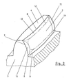
- Fig. 3 is a section through two meshing teeth 16 and 17 shown with profile modification.
- the edge line 6 On the teeth along the edge line 6 as sections of the principal Vietnamese 10, the principalausrundung 9, the foot edge 11, the involute flank 2 and the tip circle edge 8 are shown.
- the dashed line shows the foot return 14 and the tooth head the linear head withdrawal 13. These modifications were removed by the teeth grinding.
- the contact between the teeth in the cutout X only has a recognizable gap 18 in the drawing, in order to make it clear that there is an oil film (not shown) between the supporting flanks.
- Fig. 4 shows as a section X the contact area of two teeth 16 and 17.
- the head return 13 are separated from the tooth by the grinding wheel larger amounts of the tooth material.
- a burr 19 may arise, which is greater than the normal tooth roughness.
- the z. B. off of the EP 0 414 441 A2 known and initially described chemically accelerated vibratory finishing performed.
- the gears are treated chemically and mechanically within a vibrated container with a special chemical fluid mixed with non-abrasive solids.
- the burrs 19, 20 and the discontinuity at point 21, which are caused by the introduction of the profile modification at the transitions of the adjoining flank edges of top circle 8 and bottom edge 9, are removed in repeated steps.
Priority Applications (4)
| Application Number | Priority Date | Filing Date | Title |
|---|---|---|---|
| DE502006001676T DE502006001676D1 (de) | 2006-03-09 | 2006-03-09 | Verfahren zur Fertigung von evolventenförmigen Verzahnungen von Zahnrädern |
| EP06004800A EP1832370B1 (fr) | 2006-03-09 | 2006-03-09 | Procédé de fabrication d'engrenages à développante de roues dentées |
| ES06004800T ES2314766T3 (es) | 2006-03-09 | 2006-03-09 | Proceso para la fabricacion de dentados envolventes de ruedas de engranaje. |
| AT06004800T ATE409540T1 (de) | 2006-03-09 | 2006-03-09 | Verfahren zur fertigung von evolventenförmigen verzahnungen von zahnrädern |
Applications Claiming Priority (1)
| Application Number | Priority Date | Filing Date | Title |
|---|---|---|---|
| EP06004800A EP1832370B1 (fr) | 2006-03-09 | 2006-03-09 | Procédé de fabrication d'engrenages à développante de roues dentées |
Publications (2)
| Publication Number | Publication Date |
|---|---|
| EP1832370A1 true EP1832370A1 (fr) | 2007-09-12 |
| EP1832370B1 EP1832370B1 (fr) | 2008-10-01 |
Family
ID=36570771
Family Applications (1)
| Application Number | Title | Priority Date | Filing Date |
|---|---|---|---|
| EP06004800A Active EP1832370B1 (fr) | 2006-03-09 | 2006-03-09 | Procédé de fabrication d'engrenages à développante de roues dentées |
Country Status (4)
| Country | Link |
|---|---|
| EP (1) | EP1832370B1 (fr) |
| AT (1) | ATE409540T1 (fr) |
| DE (1) | DE502006001676D1 (fr) |
| ES (1) | ES2314766T3 (fr) |
Cited By (8)
| Publication number | Priority date | Publication date | Assignee | Title |
|---|---|---|---|---|
| WO2010132914A1 (fr) * | 2009-05-20 | 2010-11-25 | Miba Sinter Austria Gmbh | Roue dentée |
| WO2013054166A1 (fr) * | 2011-10-11 | 2013-04-18 | Toyota Jidosha Kabushiki Kaisha | Roues dentées et transmission |
| WO2016088577A1 (fr) * | 2014-12-05 | 2016-06-09 | 株式会社エンプラス | Engrenage hélicoïdal en résine |
| JP2016109289A (ja) * | 2014-12-05 | 2016-06-20 | 株式会社エンプラス | 樹脂製はすば歯車 |
| WO2017013344A1 (fr) * | 2015-07-20 | 2017-01-26 | Valeo Equipements Electriques Moteur | Démarreur de véhicule automobile pourvu de décrochements sur les dents de pignon |
| CN106481780A (zh) * | 2016-10-12 | 2017-03-08 | 湖南工业大学 | 一种面齿轮修缘高度及修缘量的确定方法 |
| EP3387294A4 (fr) * | 2015-12-11 | 2019-07-17 | Gear Innovations LLC | Engrenages conjugués avec contact de flanc de dent continu |
| US11054013B1 (en) * | 2021-01-08 | 2021-07-06 | Enplas Corporation | Profile modification for planetary gear device gear teeth |
Families Citing this family (4)
| Publication number | Priority date | Publication date | Assignee | Title |
|---|---|---|---|---|
| DE102012112973B4 (de) * | 2012-12-21 | 2023-08-24 | Dr. Ing. H.C. F. Porsche Aktiengesellschaft | Kraftfahrzeug mit rein elektrischem Antrieb |
| CN107025367B (zh) * | 2017-06-05 | 2019-08-23 | 太原理工大学 | 基于轮齿热弹性变形和齿轮歪斜变形的圆柱直齿轮齿廓修形方法 |
| DE102020131402A1 (de) | 2020-11-26 | 2022-06-02 | Bundesrepublik Deutschland, Vertreten Durch Das Bundesministerium Für Wirtschaft Und Energie, Dieses Vertreten Durch Den Präsidenten Der Physikalisch-Technischen Bundesanstalt | Verfahren zum Herstellen eines Formabweichungsnormals und Formabweichungsnormal |
| EP4310315A1 (fr) * | 2022-07-21 | 2024-01-24 | MAHLE International GmbH | Dispositif de démarreur et moteur à combustion interne doté de celui-ci |
Citations (5)
| Publication number | Priority date | Publication date | Assignee | Title |
|---|---|---|---|---|
| EP0229894A2 (fr) * | 1985-12-13 | 1987-07-29 | Werkzeugmaschinenfabrik Oerlikon-Bührle AG | Procédé pour meuler l'ensemble de dents de roues coniques ayant des dents incurvées dans leur sens longitudinal ainsi qu'un outil et un dispositif mettant en oeuvre le procédé |
| EP0414441A2 (fr) | 1989-08-23 | 1991-02-27 | Rem Chemicals, Inc. | Méthode et composition pour le polissage |
| EP1167825A2 (fr) | 2000-06-30 | 2002-01-02 | Eaton Corporation | Surfaces d'engrenage polies |
| EP1350601A1 (fr) * | 2002-04-02 | 2003-10-08 | Winergy AG | Procédé de traitement des engrenages |
| WO2004108356A1 (fr) | 2003-05-30 | 2004-12-16 | Rem Technologies, Inc. | Superfinition d'engrenages planétaires de grande taille |
-
2006
- 2006-03-09 DE DE502006001676T patent/DE502006001676D1/de active Active
- 2006-03-09 ES ES06004800T patent/ES2314766T3/es active Active
- 2006-03-09 EP EP06004800A patent/EP1832370B1/fr active Active
- 2006-03-09 AT AT06004800T patent/ATE409540T1/de not_active IP Right Cessation
Patent Citations (6)
| Publication number | Priority date | Publication date | Assignee | Title |
|---|---|---|---|---|
| EP0229894A2 (fr) * | 1985-12-13 | 1987-07-29 | Werkzeugmaschinenfabrik Oerlikon-Bührle AG | Procédé pour meuler l'ensemble de dents de roues coniques ayant des dents incurvées dans leur sens longitudinal ainsi qu'un outil et un dispositif mettant en oeuvre le procédé |
| EP0414441A2 (fr) | 1989-08-23 | 1991-02-27 | Rem Chemicals, Inc. | Méthode et composition pour le polissage |
| EP1167825A2 (fr) | 2000-06-30 | 2002-01-02 | Eaton Corporation | Surfaces d'engrenage polies |
| EP1350601A1 (fr) * | 2002-04-02 | 2003-10-08 | Winergy AG | Procédé de traitement des engrenages |
| EP1350601B1 (fr) | 2002-04-02 | 2004-09-08 | Winergy AG | Procédé de traitement des engrenages |
| WO2004108356A1 (fr) | 2003-05-30 | 2004-12-16 | Rem Technologies, Inc. | Superfinition d'engrenages planétaires de grande taille |
Cited By (16)
| Publication number | Priority date | Publication date | Assignee | Title |
|---|---|---|---|---|
| US9291248B2 (en) | 2009-05-20 | 2016-03-22 | Miba Sinter Austria Gmbh | Gear wheel |
| WO2010132914A1 (fr) * | 2009-05-20 | 2010-11-25 | Miba Sinter Austria Gmbh | Roue dentée |
| WO2013054166A1 (fr) * | 2011-10-11 | 2013-04-18 | Toyota Jidosha Kabushiki Kaisha | Roues dentées et transmission |
| CN103857943A (zh) * | 2011-10-11 | 2014-06-11 | 丰田自动车株式会社 | 齿轮和变速器 |
| AU2012322472B2 (en) * | 2011-10-11 | 2015-12-03 | Toyota Jidosha Kabushiki Kaisha | Toothed wheels and transmission |
| CN103857943B (zh) * | 2011-10-11 | 2016-10-19 | 丰田自动车株式会社 | 齿轮和变速器 |
| US10584784B2 (en) | 2014-12-05 | 2020-03-10 | Enplas Corporation | Resin helical gear |
| WO2016088577A1 (fr) * | 2014-12-05 | 2016-06-09 | 株式会社エンプラス | Engrenage hélicoïdal en résine |
| JP2016109289A (ja) * | 2014-12-05 | 2016-06-20 | 株式会社エンプラス | 樹脂製はすば歯車 |
| WO2017013344A1 (fr) * | 2015-07-20 | 2017-01-26 | Valeo Equipements Electriques Moteur | Démarreur de véhicule automobile pourvu de décrochements sur les dents de pignon |
| FR3039223A1 (fr) * | 2015-07-20 | 2017-01-27 | Valeo Equip Electr Moteur | Pignon de demarreur de vehicule automobile muni d'un decrochement |
| EP3387294A4 (fr) * | 2015-12-11 | 2019-07-17 | Gear Innovations LLC | Engrenages conjugués avec contact de flanc de dent continu |
| US10527149B2 (en) | 2015-12-11 | 2020-01-07 | Gear Innovations Llc | Conjugate gears with continuous tooth flank contact |
| CN106481780A (zh) * | 2016-10-12 | 2017-03-08 | 湖南工业大学 | 一种面齿轮修缘高度及修缘量的确定方法 |
| CN106481780B (zh) * | 2016-10-12 | 2018-11-27 | 湖南工业大学 | 一种面齿轮修缘高度及修缘量的确定方法 |
| US11054013B1 (en) * | 2021-01-08 | 2021-07-06 | Enplas Corporation | Profile modification for planetary gear device gear teeth |
Also Published As
| Publication number | Publication date |
|---|---|
| DE502006001676D1 (de) | 2008-11-13 |
| EP1832370B1 (fr) | 2008-10-01 |
| ATE409540T1 (de) | 2008-10-15 |
| ES2314766T3 (es) | 2009-03-16 |
Similar Documents
| Publication | Publication Date | Title |
|---|---|---|
| EP1832370B1 (fr) | Procédé de fabrication d'engrenages à développante de roues dentées | |
| DE69735631T2 (de) | Apparat und verfahren zum präzisionsschleifen von kronenrädern | |
| DE69916120T2 (de) | Verfahren zum nachbearbeiten von zahnrädern und zahnrad | |
| DE10393256B4 (de) | Planetenradsatz mit mehrlagig beschichtetem Sonnenrad | |
| DE102010006094B4 (de) | Verfahren zur Oberflächenverfestigung einer Komponente einer Windturbine | |
| DE102009059201B4 (de) | Vollprofilrolle zum Abrichten mehrgängiger zylindrischer Schleifschnecken | |
| EP3325203B1 (fr) | Procédé de pierrage de roues dentées | |
| EP2402631B1 (fr) | Train épicycloïdal pour une direction de charge principale | |
| EP2929970B1 (fr) | Procédé d'usinage d'une pièce à usiner d'une roulette de dressage | |
| EP3999270B1 (fr) | Procédé de meulage d'une roue dentée au moyen d'une vis de meulage et molette de dressage permettant de dresser la vis de meulage | |
| DE102019115294B4 (de) | Verfahren zur Herstellung eines mit einer Verzahnung oder Profilierung versehenen Werkstücks | |
| DE102017126988A1 (de) | Werkzeug, Maschine und Verfahren zum Glattwalzen von verzahnten Werkstücken | |
| CH658619A5 (de) | Werkzeug zur herstellung von aussenprofilformen. | |
| EP0293473A1 (fr) | Transmission a engrenages avec engrenement de type mixte | |
| WO1996035543A1 (fr) | Procede de finissage de la denture trempee d'une roue conique | |
| EP3756809A1 (fr) | Procédé de fabrication d'un composant d'engrenage et machine de rectification pour engrenages | |
| WO2021180633A1 (fr) | Procédé d'usinage par laminage d'une roue dentée | |
| DE102021108382A1 (de) | Verfahren zum erzeugen von verschränkungen an den zahnflanken eines innenverzahnten werkstücks | |
| DE102020204380A1 (de) | Verfahren zum schleifen von werkstücken mit schraubenförmigem profil und schleifmaschine zum herstellen derartiger werkstücke | |
| EP3993940A1 (fr) | Procédé permettant la réalisation de modifications de flancs de dent sur des dentures de pièces et outils permettant la mise en oeuvre du procédé | |
| EP0815984A1 (fr) | Procédé et dispositif pour la finition des flancs de dents d'une roue dentée sur une machine-outil | |
| WO2020078734A1 (fr) | Procédé de fabrication d'une vis sans fin d'engrenage disposée en particulier sur un arbre d'ancrage, et vis sans fin d'engrenage de ce type | |
| WO2019110519A1 (fr) | Procédé de fabrication d'une roue dentée | |
| DE102017217933A1 (de) | Verfahren und Vorrichtung zur Herstellung eines Zahnradbauteils eines Getriebes, insbesondere eines Windkraft-Planetengetriebes | |
| DE19650350C2 (de) | Werkzeug und Verfahren zum Drückwalzen eines Werkstücks mit Verzahnung |
Legal Events
| Date | Code | Title | Description |
|---|---|---|---|
| PUAI | Public reference made under article 153(3) epc to a published international application that has entered the european phase |
Free format text: ORIGINAL CODE: 0009012 |
|
| 17P | Request for examination filed |
Effective date: 20070404 |
|
| AK | Designated contracting states |
Kind code of ref document: A1 Designated state(s): AT BE BG CH CY CZ DE DK EE ES FI FR GB GR HU IE IS IT LI LT LU LV MC NL PL PT RO SE SI SK TR |
|
| AX | Request for extension of the european patent |
Extension state: AL BA HR MK YU |
|
| GRAP | Despatch of communication of intention to grant a patent |
Free format text: ORIGINAL CODE: EPIDOSNIGR1 |
|
| AKX | Designation fees paid |
Designated state(s): AT BE BG CH CY CZ DE DK EE ES FI FR GB GR HU IE IS IT LI LT LU LV MC NL PL PT RO SE SI SK TR |
|
| GRAS | Grant fee paid |
Free format text: ORIGINAL CODE: EPIDOSNIGR3 |
|
| GRAA | (expected) grant |
Free format text: ORIGINAL CODE: 0009210 |
|
| AK | Designated contracting states |
Kind code of ref document: B1 Designated state(s): AT BE BG CH CY CZ DE DK EE ES FI FR GB GR HU IE IS IT LI LT LU LV MC NL PL PT RO SE SI SK TR |
|
| REG | Reference to a national code |
Ref country code: GB Ref legal event code: FG4D Free format text: NOT ENGLISH |
|
| REG | Reference to a national code |
Ref country code: CH Ref legal event code: EP |
|
| REG | Reference to a national code |
Ref country code: IE Ref legal event code: FG4D Free format text: LANGUAGE OF EP DOCUMENT: GERMAN |
|
| REF | Corresponds to: |
Ref document number: 502006001676 Country of ref document: DE Date of ref document: 20081113 Kind code of ref document: P |
|
| PG25 | Lapsed in a contracting state [announced via postgrant information from national office to epo] |
Ref country code: SI Free format text: LAPSE BECAUSE OF FAILURE TO SUBMIT A TRANSLATION OF THE DESCRIPTION OR TO PAY THE FEE WITHIN THE PRESCRIBED TIME-LIMIT Effective date: 20081001 |
|
| REG | Reference to a national code |
Ref country code: ES Ref legal event code: FG2A Ref document number: 2314766 Country of ref document: ES Kind code of ref document: T3 |
|
| NLV1 | Nl: lapsed or annulled due to failure to fulfill the requirements of art. 29p and 29m of the patents act | ||
| REG | Reference to a national code |
Ref country code: IE Ref legal event code: FD4D |
|
| PG25 | Lapsed in a contracting state [announced via postgrant information from national office to epo] |
Ref country code: LT Free format text: LAPSE BECAUSE OF FAILURE TO SUBMIT A TRANSLATION OF THE DESCRIPTION OR TO PAY THE FEE WITHIN THE PRESCRIBED TIME-LIMIT Effective date: 20081001 Ref country code: BG Free format text: LAPSE BECAUSE OF FAILURE TO SUBMIT A TRANSLATION OF THE DESCRIPTION OR TO PAY THE FEE WITHIN THE PRESCRIBED TIME-LIMIT Effective date: 20090101 |
|
| PG25 | Lapsed in a contracting state [announced via postgrant information from national office to epo] |
Ref country code: NL Free format text: LAPSE BECAUSE OF FAILURE TO SUBMIT A TRANSLATION OF THE DESCRIPTION OR TO PAY THE FEE WITHIN THE PRESCRIBED TIME-LIMIT Effective date: 20081001 Ref country code: LV Free format text: LAPSE BECAUSE OF FAILURE TO SUBMIT A TRANSLATION OF THE DESCRIPTION OR TO PAY THE FEE WITHIN THE PRESCRIBED TIME-LIMIT Effective date: 20081001 Ref country code: PT Free format text: LAPSE BECAUSE OF FAILURE TO SUBMIT A TRANSLATION OF THE DESCRIPTION OR TO PAY THE FEE WITHIN THE PRESCRIBED TIME-LIMIT Effective date: 20090302 Ref country code: IS Free format text: LAPSE BECAUSE OF FAILURE TO SUBMIT A TRANSLATION OF THE DESCRIPTION OR TO PAY THE FEE WITHIN THE PRESCRIBED TIME-LIMIT Effective date: 20090201 Ref country code: PL Free format text: LAPSE BECAUSE OF FAILURE TO SUBMIT A TRANSLATION OF THE DESCRIPTION OR TO PAY THE FEE WITHIN THE PRESCRIBED TIME-LIMIT Effective date: 20081001 |
|
| PG25 | Lapsed in a contracting state [announced via postgrant information from national office to epo] |
Ref country code: DK Free format text: LAPSE BECAUSE OF FAILURE TO SUBMIT A TRANSLATION OF THE DESCRIPTION OR TO PAY THE FEE WITHIN THE PRESCRIBED TIME-LIMIT Effective date: 20081001 Ref country code: EE Free format text: LAPSE BECAUSE OF FAILURE TO SUBMIT A TRANSLATION OF THE DESCRIPTION OR TO PAY THE FEE WITHIN THE PRESCRIBED TIME-LIMIT Effective date: 20081001 Ref country code: IE Free format text: LAPSE BECAUSE OF FAILURE TO SUBMIT A TRANSLATION OF THE DESCRIPTION OR TO PAY THE FEE WITHIN THE PRESCRIBED TIME-LIMIT Effective date: 20081001 Ref country code: RO Free format text: LAPSE BECAUSE OF FAILURE TO SUBMIT A TRANSLATION OF THE DESCRIPTION OR TO PAY THE FEE WITHIN THE PRESCRIBED TIME-LIMIT Effective date: 20081001 |
|
| PLBE | No opposition filed within time limit |
Free format text: ORIGINAL CODE: 0009261 |
|
| STAA | Information on the status of an ep patent application or granted ep patent |
Free format text: STATUS: NO OPPOSITION FILED WITHIN TIME LIMIT |
|
| PG25 | Lapsed in a contracting state [announced via postgrant information from national office to epo] |
Ref country code: CZ Free format text: LAPSE BECAUSE OF FAILURE TO SUBMIT A TRANSLATION OF THE DESCRIPTION OR TO PAY THE FEE WITHIN THE PRESCRIBED TIME-LIMIT Effective date: 20081001 Ref country code: SE Free format text: LAPSE BECAUSE OF FAILURE TO SUBMIT A TRANSLATION OF THE DESCRIPTION OR TO PAY THE FEE WITHIN THE PRESCRIBED TIME-LIMIT Effective date: 20090101 Ref country code: IT Free format text: LAPSE BECAUSE OF FAILURE TO SUBMIT A TRANSLATION OF THE DESCRIPTION OR TO PAY THE FEE WITHIN THE PRESCRIBED TIME-LIMIT Effective date: 20081001 |
|
| 26N | No opposition filed |
Effective date: 20090702 |
|
| PG25 | Lapsed in a contracting state [announced via postgrant information from national office to epo] |
Ref country code: SK Free format text: LAPSE BECAUSE OF FAILURE TO SUBMIT A TRANSLATION OF THE DESCRIPTION OR TO PAY THE FEE WITHIN THE PRESCRIBED TIME-LIMIT Effective date: 20081001 |
|
| PG25 | Lapsed in a contracting state [announced via postgrant information from national office to epo] |
Ref country code: MC Free format text: LAPSE BECAUSE OF NON-PAYMENT OF DUE FEES Effective date: 20090331 |
|
| PG25 | Lapsed in a contracting state [announced via postgrant information from national office to epo] |
Ref country code: AT Free format text: LAPSE BECAUSE OF NON-PAYMENT OF DUE FEES Effective date: 20090309 |
|
| PG25 | Lapsed in a contracting state [announced via postgrant information from national office to epo] |
Ref country code: GR Free format text: LAPSE BECAUSE OF FAILURE TO SUBMIT A TRANSLATION OF THE DESCRIPTION OR TO PAY THE FEE WITHIN THE PRESCRIBED TIME-LIMIT Effective date: 20090102 |
|
| REG | Reference to a national code |
Ref country code: CH Ref legal event code: PL |
|
| PG25 | Lapsed in a contracting state [announced via postgrant information from national office to epo] |
Ref country code: LI Free format text: LAPSE BECAUSE OF NON-PAYMENT OF DUE FEES Effective date: 20100331 Ref country code: CH Free format text: LAPSE BECAUSE OF NON-PAYMENT OF DUE FEES Effective date: 20100331 |
|
| PG25 | Lapsed in a contracting state [announced via postgrant information from national office to epo] |
Ref country code: LU Free format text: LAPSE BECAUSE OF NON-PAYMENT OF DUE FEES Effective date: 20090309 |
|
| PG25 | Lapsed in a contracting state [announced via postgrant information from national office to epo] |
Ref country code: HU Free format text: LAPSE BECAUSE OF FAILURE TO SUBMIT A TRANSLATION OF THE DESCRIPTION OR TO PAY THE FEE WITHIN THE PRESCRIBED TIME-LIMIT Effective date: 20090402 |
|
| PG25 | Lapsed in a contracting state [announced via postgrant information from national office to epo] |
Ref country code: TR Free format text: LAPSE BECAUSE OF FAILURE TO SUBMIT A TRANSLATION OF THE DESCRIPTION OR TO PAY THE FEE WITHIN THE PRESCRIBED TIME-LIMIT Effective date: 20081001 |
|
| PG25 | Lapsed in a contracting state [announced via postgrant information from national office to epo] |
Ref country code: CY Free format text: LAPSE BECAUSE OF FAILURE TO SUBMIT A TRANSLATION OF THE DESCRIPTION OR TO PAY THE FEE WITHIN THE PRESCRIBED TIME-LIMIT Effective date: 20081001 |
|
| PG25 | Lapsed in a contracting state [announced via postgrant information from national office to epo] |
Ref country code: DE Free format text: LAPSE BECAUSE OF NON-PAYMENT OF DUE FEES Effective date: 20111001 |
|
| REG | Reference to a national code |
Ref country code: DE Ref legal event code: R082 Ref document number: 502006001676 Country of ref document: DE |
|
| REG | Reference to a national code |
Ref country code: DE Ref legal event code: R081 Ref document number: 502006001676 Country of ref document: DE Owner name: SIEMENS AKTIENGESELLSCHAFT, DE Free format text: FORMER OWNER: WINERGY AG, 46562 VOERDE, DE Effective date: 20130625 Ref country code: DE Ref legal event code: R081 Ref document number: 502006001676 Country of ref document: DE Owner name: FLENDER GMBH, DE Free format text: FORMER OWNER: WINERGY AG, 46562 VOERDE, DE Effective date: 20130625 |
|
| REG | Reference to a national code |
Ref country code: GB Ref legal event code: 732E Free format text: REGISTERED BETWEEN 20131024 AND 20131030 |
|
| REG | Reference to a national code |
Ref country code: ES Ref legal event code: PC2A Owner name: SIEMENS AKTIENGESELLSCHAFT Effective date: 20131126 |
|
| REG | Reference to a national code |
Ref country code: FR Ref legal event code: TP Owner name: SIEMENS AKTIENGESELLSCHAFT, DE Effective date: 20131127 |
|
| REG | Reference to a national code |
Ref country code: FR Ref legal event code: PLFP Year of fee payment: 11 |
|
| REG | Reference to a national code |
Ref country code: FR Ref legal event code: PLFP Year of fee payment: 12 |
|
| REG | Reference to a national code |
Ref country code: DE Ref legal event code: R081 Ref document number: 502006001676 Country of ref document: DE Owner name: FLENDER GMBH, DE Free format text: FORMER OWNER: SIEMENS AKTIENGESELLSCHAFT, 80333 MUENCHEN, DE |
|
| REG | Reference to a national code |
Ref country code: ES Ref legal event code: PC2A Owner name: FLENDER GMBH Effective date: 20171219 |
|
| REG | Reference to a national code |
Ref country code: GB Ref legal event code: 732E Free format text: REGISTERED BETWEEN 20171207 AND 20171213 |
|
| REG | Reference to a national code |
Ref country code: BE Ref legal event code: PD Owner name: FLENDER GMBH; DE Free format text: DETAILS ASSIGNMENT: CHANGE OF OWNER(S), AFFECTATION / CESSION; FORMER OWNER NAME: SIEMENS AKTIENGESELLSCHAFT Effective date: 20171117 |
|
| REG | Reference to a national code |
Ref country code: FR Ref legal event code: PLFP Year of fee payment: 13 |
|
| REG | Reference to a national code |
Ref country code: FR Ref legal event code: TP Owner name: FLENDER GMBH, DE Effective date: 20180316 |
|
| REG | Reference to a national code |
Ref country code: DE Ref legal event code: R082 Ref document number: 502006001676 Country of ref document: DE Representative=s name: MICHALSKI HUETTERMANN & PARTNER PATENTANWAELTE, DE |
|
| PGFP | Annual fee paid to national office [announced via postgrant information from national office to epo] |
Ref country code: GB Payment date: 20220321 Year of fee payment: 17 Ref country code: FI Payment date: 20220322 Year of fee payment: 17 |
|
| PGFP | Annual fee paid to national office [announced via postgrant information from national office to epo] |
Ref country code: FR Payment date: 20220322 Year of fee payment: 17 Ref country code: BE Payment date: 20220321 Year of fee payment: 17 |
|
| PGFP | Annual fee paid to national office [announced via postgrant information from national office to epo] |
Ref country code: ES Payment date: 20220527 Year of fee payment: 17 |
|
| PGFP | Annual fee paid to national office [announced via postgrant information from national office to epo] |
Ref country code: DE Payment date: 20230328 Year of fee payment: 18 |
|
| PG25 | Lapsed in a contracting state [announced via postgrant information from national office to epo] |
Ref country code: FI Free format text: LAPSE BECAUSE OF NON-PAYMENT OF DUE FEES Effective date: 20230309 |
|
| GBPC | Gb: european patent ceased through non-payment of renewal fee |
Effective date: 20230309 |
|
| REG | Reference to a national code |
Ref country code: BE Ref legal event code: MM Effective date: 20230331 |
|
| PG25 | Lapsed in a contracting state [announced via postgrant information from national office to epo] |
Ref country code: GB Free format text: LAPSE BECAUSE OF NON-PAYMENT OF DUE FEES Effective date: 20230309 |
|
| PG25 | Lapsed in a contracting state [announced via postgrant information from national office to epo] |
Ref country code: GB Free format text: LAPSE BECAUSE OF NON-PAYMENT OF DUE FEES Effective date: 20230309 Ref country code: FR Free format text: LAPSE BECAUSE OF NON-PAYMENT OF DUE FEES Effective date: 20230331 |
|
| PG25 | Lapsed in a contracting state [announced via postgrant information from national office to epo] |
Ref country code: BE Free format text: LAPSE BECAUSE OF NON-PAYMENT OF DUE FEES Effective date: 20230331 |