EP0293473A1 - Transmission a engrenages avec engrenement de type mixte - Google Patents
Transmission a engrenages avec engrenement de type mixte Download PDFInfo
- Publication number
- EP0293473A1 EP0293473A1 EP87900731A EP87900731A EP0293473A1 EP 0293473 A1 EP0293473 A1 EP 0293473A1 EP 87900731 A EP87900731 A EP 87900731A EP 87900731 A EP87900731 A EP 87900731A EP 0293473 A1 EP0293473 A1 EP 0293473A1
- Authority
- EP
- European Patent Office
- Prior art keywords
- tooth
- profile
- section
- nowikow
- teeth
- Prior art date
- Legal status (The legal status is an assumption and is not a legal conclusion. Google has not performed a legal analysis and makes no representation as to the accuracy of the status listed.)
- Granted
Links
Images


Classifications
-
- F—MECHANICAL ENGINEERING; LIGHTING; HEATING; WEAPONS; BLASTING
- F16—ENGINEERING ELEMENTS AND UNITS; GENERAL MEASURES FOR PRODUCING AND MAINTAINING EFFECTIVE FUNCTIONING OF MACHINES OR INSTALLATIONS; THERMAL INSULATION IN GENERAL
- F16H—GEARING
- F16H55/00—Elements with teeth or friction surfaces for conveying motion; Worms, pulleys or sheaves for gearing mechanisms
- F16H55/02—Toothed members; Worms
- F16H55/08—Profiling
- F16H55/0806—Involute profile
-
- F—MECHANICAL ENGINEERING; LIGHTING; HEATING; WEAPONS; BLASTING
- F16—ENGINEERING ELEMENTS AND UNITS; GENERAL MEASURES FOR PRODUCING AND MAINTAINING EFFECTIVE FUNCTIONING OF MACHINES OR INSTALLATIONS; THERMAL INSULATION IN GENERAL
- F16H—GEARING
- F16H55/00—Elements with teeth or friction surfaces for conveying motion; Worms, pulleys or sheaves for gearing mechanisms
- F16H55/02—Toothed members; Worms
- F16H55/08—Profiling
- F16H55/0826—Novikov-Wildhaber profile
Definitions
- the present invention relates to the field of mechanical engineering and relates in particular to a wheel gear with mixed teeth.
- the invention can be used in highly stressed ship engines. Aircraft, agricultural and other machines are most advantageously used.
- a wheel gear with mixed teeth is characterized by a design of the tooth profile flank, which is composed of several sections, which are designed according to different laws with regard to the peculiarities of their stress and deformation state.
- the tooth profile of the mixed toothing has, at the tooth head and foot, similarly designed distances like the Nowikow-type toothing as well as a connecting path, which is designed after an involute (hereinafter referred to as an involute path) and which coincide with the theoretical profile, which is a predetermined one Gear ratio guaranteed when meshing absolutely rigid gears.
- an involute path which is designed after an involute (hereinafter referred to as an involute path) and which coincide with the theoretical profile, which is a predetermined one Gear ratio guaranteed when meshing absolutely rigid gears.
- the gear train Since the distances of the tooth profile of the wheel transmission with mixed teeth kinematically not ge with each other are coupled, the gear train has a longer axial engagement time of the teeth and their generally favorable shape, an increased load-bearing capacity of the teeth in each engagement area. This allows the load to be transmitted to be increased in comparison to simple gears.
- the radius of curvature of the path which binds a Nowikow toothing type path with an involute path and represents a tensile stress concentrator at the tooth tip, leads to a shorter arm of the bending force attack, to a tooth tip thickness increase on the rolling circle and to Tooth root thickness enlargement in normal section, to enlarge the tooth surface to be gripped.
- the routes of the Nowikow toothing type are therefore not only characterized by their high working capacity, which is determined by the criterion of fatigue strength under the effect of the roller stresses, but also by increased fatigue strength under the influence of the bending forces out.
- the known wheel gear is formed by gears, the tooth profile flank each of which has a path which is approximately designed as an involute and is connected to two paths designed as a tooth profile of the Nowikow tooth system.
- the involute path is located in an area that passes through the gearwheel rolling path, and the two remaining paths are outside of this rolling path.
- the tooth profile flank coincides with the flank of the theoretical profile, while the Evol ventenumble shows a deviation from the theoretical profile in the direction of tooth thickness reduction. This deviation is determined as the maximum value of the possible wear of the teeth in the Frofil sections formed as a tooth profile of the Nowikow tooth system.
- This wheel gear works as a wheel gear of the Nowikow type and guarantees an insignificant increase in the load-bearing capacity only thanks to the reduction in the maximum roller stresses in the tooth body due to the fact that the involute paths are disengaged.
- the lower limit of this section is arranged at a certain distance from the pitch circle, which is given as 0.15 times the tooth tip height. This leads to a more than 20% increase in the fatigue strength of the teeth under the action of the bending force if the wheel gear works as a wheel gear of the Nowikow type.
- the non-uniformity of the load distribution and the short duration of engagement of the teeth lead to an increase in the axial external dimensions of the transmission or the axial component of the engagement forces, to a reduction in the diameter division and, as a result, to a limited increase in the load capacity of the transmission and to a reduction in the working capacity of the bearings due to the change in position resulting force over the rim width of the gear.
- the known wheel gear is formed by gears, the tooth profile flank each of which has a path which is approximately designed as an involute and is connected to two paths designed as a tooth profile of the Nowikow tooth system.
- the involute path is located in an area that passes through the gearwheel rolling path, and the two remaining paths are outside of this rolling path.
- the invention has for its object to develop such a wheel gear with mixed teeth, in which the increase in load capacity, efficiency, lengthening the service life, improving the vibroacoustic characteristics, reducing the amount of metal and the outer dimensions by constructively changing the profile edge of the Intervention participating teeth is guaranteed.
- a geared wheel with mixed toothing which is formed by gears, in each of which the tooth profile edge has a path which is roughly designed like an involute, is located in an area running through the pitch circle of the gearwheel and is connected at least to a path designed as a tooth profile of the Nowikow toothing and located in an area lying outside the pitch circle of the gearwheel, according to the invention the tooth profile participating in the engagement flank has a deviation from the flank of the theoretical tooth profile in the direction of the tooth thickness increase in at least two sections.
- the lines of the Nowikow toothing in the mixed toothing have an increased wear resistance and wear resistance relative to any other simple toothing which is not at the pitch point.
- the distance formed as the tooth profile of the Nowikow toothing is the first Profile flank on the tooth head and the tooth profile of the Nowikow toothing, located on the opposite side of the second profile flank on the opposite side relative to the axis of the tooth profile, the deviation of the profile flank of the tooth taking part in the engagement, which is formed approximately after an involute, in is essentially the same as the deviation of the profile flank of the tooth participating in the engagement in the path designed as a tooth profile of the Nowikow toothing.
- Such a design of the tooth profile increases the profile coverage of the involute paths. This is achieved by increasing the involute path of the tooth profile, for example in the direction of the tooth head or foot.
- the wheel gear can be produced with mixed teeth, the ring gear width b of which is less than 0.7 times the axis engagement pitch of the teeth: b w ⁇ 0.7 P.
- the tooth profiles of the gear wheel and pinion are asymmetrical and are manufactured with one and the same tool during machining on gear hobbing machines.
- the profile section on the tooth base designed according to the type of Nowikow serration is circumscribed by arcs of two circles, which are gently conjugated to one another and have a spacing point between the bulbs which distance is calculated from the following formula:
- Such a constructive design of the tooth profile ensures a low sensitivity of the Nowikow tooth system to the deviations ⁇ a ' w > 0 and ⁇ a w ⁇ o of the center distance a w of the wheel transmission, which deviations occur, for example, due to warpage of the housing and the components of the reduction gear of the operation, especially if it is.
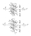
- a helical-spur gear transmission with mixed toothing designed according to the invention and which can be used in a highly stressed drive is provided by a drive Rad- pinion 1 (Fig.1) with teeth 2 and an output gear 3 with teeth 4 are formed.
- the profile flank 5 of the tooth 2 has an involute path 6, which is located in an area running through the pitch circle 7 of the pinion 1, and two paths 8 and 9, which are designed as tooth profiles of the Nowikow toothing and are arranged outside the pitch circle 7.
- the profile flank 10 of the tooth 4 has an involute path 11, which is located in an area running through the pitch circle 12 of the gear wheel 3, and two paths 13 and 14, which are designed as tooth profiles of the Nowikow toothing and are arranged outside the pitch circle 12.
- the Frcfil flank 5 of the tooth 2 has a deviation ⁇ 1N in the path of the Nowikow toothing on the tooth base. in the involute path a deviation ⁇ 1 ⁇ asw. from the flank 15 of the theoretical profile of the tooth 2 in the direction of the tooth thickness increase, and the profile flank 10 of the tooth 4 has a deviation ⁇ 3N in the path of the Nowikowik toothing on the tooth head, a deviation ⁇ 3 ⁇ etc. in the involute path from the flank 16 of the theoretical profile of the tooth 4 in the direction of the tooth thickness increase.
- the flanks 15 and 16 of the theoretical profiles of teeth 2 and 4 are each indicated by a dotted line. When absolutely rigid gears are engaged, such theoretical profiles ensure a predetermined transmission ratio.
- the total deviation ⁇ ⁇ N will be the same in the profile section 9 of tooth 2 and in profile section 13 of tooth 4 as the sum of the deviations ⁇ 1N and ⁇ 3N , which in the normal section of the teeth relative to the partial line in FIG
- the line of action of the resulting forces, which are absorbed by the teeth 2 and 4 participating in the intervention, are measured:
- the teeth are not absolutely rigid bodies, but have finite rigidity, their resilience and rigidity are unequal in the involute sections and in the Nowikow toothing sections.
- the structural design of the profiles with a total difference difference is therefore of major practical importance. in the route of the Nowikow gearing and in the involute route, which is calculated from the following formula:
- the difference ⁇ is 0.04 mm.
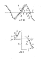
- FIG. 5 For illustration, a segment of the gearwheel 3 with the teeth 4 is shown in FIG. 5, at which points of contact on the tooth head and base can be recognized, which had arisen as a result of the engagement of these teeth with the teeth 2 of the pinion 1.
- the load capacity of the involute sections 6 and 11 of the teeth 2, 4 corresponds to their load-bearing capacity .
- the involute sections 6, 11 take on a load F ⁇ which corresponds to their load-bearing capacity according to the relevant criterion.
- the high load capacity of the wheel transmission is due to the increase in the load F N in the routes 9 and 13 or 8 and 14 of the Nowikow gearing and the most effective use of the involute paths 6, 11 of the profile, which are located in the intersection of the tooth profile with the pitch circle of the respective gear.
- FIG. 9 shows a segment of the gearwheel 3 with the teeth 4, at which contact points can be recognized, which have developed as a result of their dynamic engagement with the teeth 2 of the pinion 1.
- the extended engagement time and relatively even load distribution on the sprocket allow the gear transmission with mixed toothing to be designed with a smaller sprocket width b w compared to the axis engagement pitch, e.g. b w ⁇ 0.7 ⁇ P, thereby reducing the external dimensions and the metal expenditure of this gear transmission.
- the diameter division of the teeth can be increased and in this way their roller stresses and bending stresses can be reduced or the size of the axial component of the engagement forces and the bearing load can be reduced.
- the profile flank 17 (FIG. 10) of a tooth 18 and the profile flank 19 of a tooth 20, which participate in the engagement each have two distances exhibit.
- the path 21 of the first profile flank 19 of the tooth 20 is designed as a tooth profile of the Nowikow toothing and is arranged on the tooth head.
- the other section 22 of the second profile flank 23 of the tooth 20 is likewise designed as a tooth profile of the Nowikow toothing and is arranged on the tooth base on the opposite side relative to the axis of the tooth profile 20.
- Lines 24 and 25 are designed after an involute.
- the total deviation difference ⁇ is zero in the path of the Nowikow toothing and in the involute path, which is illustrated in FIG. 10, in which an end section is represented by a pair of racks, the rolling lines 26 of which coincide.
- the gear wheel with mixed teeth can be designed with a ring gear width b W that is smaller than 0.7 times the axis engagement pitch of the teeth:
- the tooth profiles of the gear wheel and the pinion are asymmetrical and are cut with one and the same tool during machining on gear cutting machines.
- the curvature of the path 31 has one Sign that is opposite to the curvature of distance 27 of the Nowikow tooth system.
- the section 32 of a profile flank 33 which is designed as a tooth profile of the Nowikow toothing and is arranged on the tooth base 29, connects to an involute section 34 with the aid of a second convex curvilinear section 35.
- the curvature of the section 35 has a sign that the curvature route 32 of the Nowikow gearing is opposite.
- the curvature radius of the first curvilinear segment 31 is ⁇ p 1
- the radius of curvature of the second curvilinear segment 35 is ⁇ p 2 .
- the radius of curvature ⁇ p 2 is larger than the radius ⁇ p 1 .
- the value of ⁇ p 2 is selected from the following ratio:
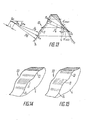
- the low sensitivity of sections 13 and 14 (FIG. 14) of the Nowikow tooth system to the center distance error ⁇ 'W> 0 is illustrated by the position of the contact points which are offset in the direction of involute section 11, but within sections 13 and 14 lie.
- the low sensitivity of the sections 13 and 14 (FIG. 15) of the Nowikow tooth system is illustrated by the position of the contact points, which are at maximum distance from the involute section 11 but lie within the sections 13, 14.
- the tooth profiles of the gears described above, which form the gear transmission with mixed teeth, can e.g. be made by means of a rack type tooth machining tool.
- Gearwheels with mixed toothing can be designed as helical, bevel and hypoid gearboxes and can be used in aircraft, ship, transport machine, general gear construction and other branches of mechanical engineering. They are more effective than involute and Nowikow gears.
- the mixed interlocking In the case of drives and reduction gears in which the mixed interlocking is used, the 1.25 to 2.0-fold increase in the load-bearing capacity compared to the involute interlocking and their 1.3 to 1.6-fold increase compared to the Nowikow interlocking is guaranteed.
- the use of the mixed toothing allows the resource of the wheel gears to be increased 2 to 10 times or, depending on the geometric data and stress conditions, to reduce their external dimensions and metal expenditure by 5 to 30%.
- the equipment used for the involute toothing is used in the manufacture of the wheel gear with mixed toothing and the necessary tooth processing tools.
- the wheel pairs of a helical-spur gear or an arrow gear with mixed teeth are cut with one and the same tool.
Landscapes
- Engineering & Computer Science (AREA)
- General Engineering & Computer Science (AREA)
- Mechanical Engineering (AREA)
- Gears, Cams (AREA)
- Nitrogen And Oxygen Or Sulfur-Condensed Heterocyclic Ring Systems (AREA)
- Rotary Pumps (AREA)
Abstract
Applications Claiming Priority (1)
| Application Number | Priority Date | Filing Date | Title |
|---|---|---|---|
| PCT/SU1986/000110 WO1988003623A1 (fr) | 1986-11-03 | 1986-11-03 | Transmission a engrenages avec engrenement de type mixte |
Publications (3)
| Publication Number | Publication Date |
|---|---|
| EP0293473A1 true EP0293473A1 (fr) | 1988-12-07 |
| EP0293473A4 EP0293473A4 (fr) | 1990-01-08 |
| EP0293473B1 EP0293473B1 (fr) | 1992-07-29 |
Family
ID=21617052
Family Applications (1)
| Application Number | Title | Priority Date | Filing Date |
|---|---|---|---|
| EP87900731A Expired - Lifetime EP0293473B1 (fr) | 1986-11-03 | 1986-11-03 | Transmission a engrenages avec engrenement de type mixte |
Country Status (5)
| Country | Link |
|---|---|
| EP (1) | EP0293473B1 (fr) |
| JP (1) | JP2728670B2 (fr) |
| DE (1) | DE3686267D1 (fr) |
| IN (1) | IN168893B (fr) |
| WO (1) | WO1988003623A1 (fr) |
Cited By (4)
| Publication number | Priority date | Publication date | Assignee | Title |
|---|---|---|---|---|
| WO1992015802A1 (fr) * | 1991-03-09 | 1992-09-17 | Robert Bosch Gmbh | Engrenage a vis sans fin |
| FR2675212A1 (fr) * | 1991-04-15 | 1992-10-16 | Danfoss As | Jeu de roues dentees a usages hydrauliques et procede pour son assemblage. |
| WO2007008096A1 (fr) | 2005-07-05 | 2007-01-18 | German Alexandrovich Zhuravlev | Engrenage |
| DE102018201008A1 (de) * | 2018-01-23 | 2019-07-25 | Ford Global Technologies, Llc | Bauteil für Schneckengetriebe mit konkaver Vertiefung in Zahnflanken |
Families Citing this family (6)
| Publication number | Priority date | Publication date | Assignee | Title |
|---|---|---|---|---|
| US5341699A (en) * | 1993-04-06 | 1994-08-30 | Axicon Gear Company | Zero dynamic increment gearing |
| US6837123B2 (en) | 2001-03-23 | 2005-01-04 | Hawkins Richard M | Non-involute gears with conformal contact |
| CN1898486A (zh) * | 2003-12-18 | 2007-01-17 | 创世纪合伙有限公司 | 轮齿齿廓曲率 |
| US20100317483A1 (en) * | 2009-06-10 | 2010-12-16 | Eaton Corporation | High performance differential |
| JP5955705B2 (ja) * | 2012-08-28 | 2016-07-20 | 大岡技研株式会社 | 太陽歯車 |
| CN104976316A (zh) * | 2015-06-10 | 2015-10-14 | 宁夏大学 | 一种多圆弧齿廓齿轮 |
Citations (1)
| Publication number | Priority date | Publication date | Assignee | Title |
|---|---|---|---|---|
| SU1075041A1 (ru) * | 1980-12-26 | 1984-02-23 | Ростовский Ордена Трудового Красного Знамени Государственный Университет | Зубчата передача точечного или смешанного зацеплени |
Family Cites Families (2)
| Publication number | Priority date | Publication date | Assignee | Title |
|---|---|---|---|---|
| SU929915A1 (ru) * | 1977-05-19 | 1982-05-23 | Ростовский Ордена Трудового Красного Знамени Государственный Университет | Зубчата передача |
| SU929917A1 (ru) * | 1977-06-22 | 1982-05-23 | Ростовский Ордена Трудового Красного Знамени Государственный Университет | Зубчата передача |
-
1986
- 1986-11-03 JP JP62500955A patent/JP2728670B2/ja not_active Expired - Fee Related
- 1986-11-03 WO PCT/SU1986/000110 patent/WO1988003623A1/fr active IP Right Grant
- 1986-11-03 DE DE8787900731T patent/DE3686267D1/de not_active Expired - Fee Related
- 1986-11-03 EP EP87900731A patent/EP0293473B1/fr not_active Expired - Lifetime
- 1986-12-31 IN IN958/CAL/86A patent/IN168893B/en unknown
Patent Citations (1)
| Publication number | Priority date | Publication date | Assignee | Title |
|---|---|---|---|---|
| SU1075041A1 (ru) * | 1980-12-26 | 1984-02-23 | Ростовский Ордена Трудового Красного Знамени Государственный Университет | Зубчата передача точечного или смешанного зацеплени |
Non-Patent Citations (2)
| Title |
|---|
| Keine weitere Entgegenhaltungen. * |
| See also references of WO8803623A1 * |
Cited By (7)
| Publication number | Priority date | Publication date | Assignee | Title |
|---|---|---|---|---|
| WO1992015802A1 (fr) * | 1991-03-09 | 1992-09-17 | Robert Bosch Gmbh | Engrenage a vis sans fin |
| FR2675212A1 (fr) * | 1991-04-15 | 1992-10-16 | Danfoss As | Jeu de roues dentees a usages hydrauliques et procede pour son assemblage. |
| GB2255136A (en) * | 1991-04-15 | 1992-10-28 | Danfoss As | Gear wheel assembly for use in a hydraulic device. |
| WO2007008096A1 (fr) | 2005-07-05 | 2007-01-18 | German Alexandrovich Zhuravlev | Engrenage |
| EP1908992A1 (fr) * | 2005-07-05 | 2008-04-09 | German Alexandrovich Zhuravlev | Engrenage |
| EP1908992A4 (fr) * | 2005-07-05 | 2009-06-10 | German Alexandrovich Zhuravlev | Engrenage |
| DE102018201008A1 (de) * | 2018-01-23 | 2019-07-25 | Ford Global Technologies, Llc | Bauteil für Schneckengetriebe mit konkaver Vertiefung in Zahnflanken |
Also Published As
| Publication number | Publication date |
|---|---|
| JPH01501331A (ja) | 1989-05-11 |
| EP0293473A4 (fr) | 1990-01-08 |
| IN168893B (fr) | 1991-07-06 |
| DE3686267D1 (de) | 1992-09-03 |
| WO1988003623A1 (fr) | 1988-05-19 |
| EP0293473B1 (fr) | 1992-07-29 |
| JP2728670B2 (ja) | 1998-03-18 |
Similar Documents
| Publication | Publication Date | Title |
|---|---|---|
| EP1908992B1 (fr) | Engrenage | |
| DE19754489B4 (de) | Zahnkette | |
| EP0316713A2 (fr) | Transmission planétaire | |
| CH631247A5 (de) | Planetengetriebe. | |
| EP2532926A1 (fr) | Engrenage excentrique et cycloïdal de profils à dents avec des dents hélicoïdales | |
| EP1402200A1 (fr) | Roue dentee a surface de roulement cintree torique et engrenage dote d'une telle roue | |
| DE2512651A1 (de) | Geraeuscharmes zahnradgetriebe | |
| DE102010021771A1 (de) | Kegelzahnrad eines Kegelgetriebes | |
| EP3653325B1 (fr) | Procédé de production par enlèvement de matière d'une roue dentée présentant une denture à double inclinaison | |
| EP1723352B1 (fr) | Entrainement auxiliaire de moteur dans un vehicule a moteur, pourvu d'une transmission par engrenages | |
| EP0293473B1 (fr) | Transmission a engrenages avec engrenement de type mixte | |
| EP2929970B1 (fr) | Procédé d'usinage d'une pièce à usiner d'une roulette de dressage | |
| WO2013127595A1 (fr) | Train d'engrenages, en particulier pour un giravion | |
| DE10203983B4 (de) | Getriebe | |
| EP1440254A1 (fr) | Engrenage a rainures de lubrification | |
| DE112006004069B4 (de) | Gleichlaufgelenk nach Art eines Gegenbahngelenkes | |
| EP3406940A1 (fr) | Appariement de roue dentée pour un engrenage à roues-hélices, engrenage à roues-hélices comprenant un tel appariement de roue dentée et utilisation d'un tel appariement dans des engrenages à roues-hélices | |
| DE6803440U (de) | Walzanmatrize zum kalten formen ein pfellzahnraedern | |
| DE3034133C2 (de) | Planetengetriebe | |
| DE2446172A1 (de) | Evolventen-stirnradverzahnung | |
| DE212020000799U1 (de) | Zahnradübertragung mit Präzessionsbewegung | |
| DE1625006B1 (de) | Stirnradgetriebe mit Spielausgleich bei Wellen mit veraenderlichem Abstand | |
| DE102019212221A1 (de) | Wellgetriebe | |
| DE102022124529B3 (de) | Flachgetriebe | |
| DD238094A1 (de) | Geometrische anordnung einer verzahnung und herstellungsverfahren von zahnraedern |
Legal Events
| Date | Code | Title | Description |
|---|---|---|---|
| PUAI | Public reference made under article 153(3) epc to a published international application that has entered the european phase |
Free format text: ORIGINAL CODE: 0009012 |
|
| 17P | Request for examination filed |
Effective date: 19880629 |
|
| AK | Designated contracting states |
Kind code of ref document: A1 Designated state(s): DE FR GB IT SE |
|
| A4 | Supplementary search report drawn up and despatched |
Effective date: 19900108 |
|
| ITCL | It: translation for ep claims filed |
Representative=s name: FIAMMENGHI FIAMMENGHI RACHELI |
|
| GBC | Gb: translation of claims filed (gb section 78(7)/1977) | ||
| EL | Fr: translation of claims filed | ||
| 17Q | First examination report despatched |
Effective date: 19910617 |
|
| GRAA | (expected) grant |
Free format text: ORIGINAL CODE: 0009210 |
|
| AK | Designated contracting states |
Kind code of ref document: B1 Designated state(s): DE FR GB IT SE |
|
| REF | Corresponds to: |
Ref document number: 3686267 Country of ref document: DE Date of ref document: 19920903 |
|
| ET | Fr: translation filed | ||
| GBT | Gb: translation of ep patent filed (gb section 77(6)(a)/1977) | ||
| ITF | It: translation for a ep patent filed |
Owner name: DR. ING. A. RACHELI & C |
|
| PLBE | No opposition filed within time limit |
Free format text: ORIGINAL CODE: 0009261 |
|
| STAA | Information on the status of an ep patent application or granted ep patent |
Free format text: STATUS: NO OPPOSITION FILED WITHIN TIME LIMIT |
|
| 26N | No opposition filed | ||
| REG | Reference to a national code |
Ref country code: GB Ref legal event code: 732E |
|
| REG | Reference to a national code |
Ref country code: FR Ref legal event code: TP |
|
| ITPR | It: changes in ownership of a european patent |
Owner name: CESSIONE;GERMAN ALEXANDROVICH ZHURAVLEV |
|
| EAL | Se: european patent in force in sweden |
Ref document number: 87900731.8 |
|
| PGFP | Annual fee paid to national office [announced via postgrant information from national office to epo] |
Ref country code: GB Payment date: 19961025 Year of fee payment: 11 |
|
| PGFP | Annual fee paid to national office [announced via postgrant information from national office to epo] |
Ref country code: DE Payment date: 19961108 Year of fee payment: 11 |
|
| PGFP | Annual fee paid to national office [announced via postgrant information from national office to epo] |
Ref country code: FR Payment date: 19961111 Year of fee payment: 11 |
|
| PGFP | Annual fee paid to national office [announced via postgrant information from national office to epo] |
Ref country code: SE Payment date: 19961118 Year of fee payment: 11 |
|
| PG25 | Lapsed in a contracting state [announced via postgrant information from national office to epo] |
Ref country code: GB Free format text: LAPSE BECAUSE OF NON-PAYMENT OF DUE FEES Effective date: 19971103 |
|
| PG25 | Lapsed in a contracting state [announced via postgrant information from national office to epo] |
Ref country code: SE Free format text: LAPSE BECAUSE OF NON-PAYMENT OF DUE FEES Effective date: 19971104 |
|
| PG25 | Lapsed in a contracting state [announced via postgrant information from national office to epo] |
Ref country code: FR Free format text: THE PATENT HAS BEEN ANNULLED BY A DECISION OF A NATIONAL AUTHORITY Effective date: 19971130 |
|
| GBPC | Gb: european patent ceased through non-payment of renewal fee |
Effective date: 19971103 |
|
| PG25 | Lapsed in a contracting state [announced via postgrant information from national office to epo] |
Ref country code: DE Free format text: LAPSE BECAUSE OF NON-PAYMENT OF DUE FEES Effective date: 19980801 |
|
| EUG | Se: european patent has lapsed |
Ref document number: 87900731.8 |
|
| REG | Reference to a national code |
Ref country code: FR Ref legal event code: ST |
|
| PG25 | Lapsed in a contracting state [announced via postgrant information from national office to epo] |
Ref country code: IT Free format text: LAPSE BECAUSE OF NON-PAYMENT OF DUE FEES;WARNING: LAPSES OF ITALIAN PATENTS WITH EFFECTIVE DATE BEFORE 2007 MAY HAVE OCCURRED AT ANY TIME BEFORE 2007. THE CORRECT EFFECTIVE DATE MAY BE DIFFERENT FROM THE ONE RECORDED. Effective date: 20051103 |