EP1832370A1 - Process of manufacturing involute gear tooth system - Google Patents
Process of manufacturing involute gear tooth system Download PDFInfo
- Publication number
- EP1832370A1 EP1832370A1 EP06004800A EP06004800A EP1832370A1 EP 1832370 A1 EP1832370 A1 EP 1832370A1 EP 06004800 A EP06004800 A EP 06004800A EP 06004800 A EP06004800 A EP 06004800A EP 1832370 A1 EP1832370 A1 EP 1832370A1
- Authority
- EP
- European Patent Office
- Prior art keywords
- flank
- involute
- grinding
- tooth
- steel
- Prior art date
- Legal status (The legal status is an assumption and is not a legal conclusion. Google has not performed a legal analysis and makes no representation as to the accuracy of the status listed.)
- Granted
Links
- 238000004519 manufacturing process Methods 0.000 title claims abstract description 11
- 238000000034 method Methods 0.000 title claims description 11
- 230000008569 process Effects 0.000 title claims description 5
- 238000000227 grinding Methods 0.000 claims abstract description 27
- 230000004048 modification Effects 0.000 claims abstract description 12
- 238000012986 modification Methods 0.000 claims abstract description 12
- 239000000126 substance Substances 0.000 claims abstract description 9
- 229910000831 Steel Inorganic materials 0.000 claims abstract description 5
- 239000010959 steel Substances 0.000 claims abstract description 5
- 230000015572 biosynthetic process Effects 0.000 claims abstract description 4
- 239000012530 fluid Substances 0.000 claims abstract description 4
- 238000005121 nitriding Methods 0.000 claims abstract description 3
- 230000000694 effects Effects 0.000 claims description 6
- 239000007788 liquid Substances 0.000 claims description 6
- 229910000760 Hardened steel Inorganic materials 0.000 claims 1
- 229910000851 Alloy steel Inorganic materials 0.000 abstract 1
- 239000007787 solid Substances 0.000 description 9
- 230000007704 transition Effects 0.000 description 8
- 238000009499 grossing Methods 0.000 description 7
- 238000010438 heat treatment Methods 0.000 description 7
- 239000000463 material Substances 0.000 description 7
- 238000012545 processing Methods 0.000 description 6
- 230000005540 biological transmission Effects 0.000 description 4
- 238000003801 milling Methods 0.000 description 4
- 230000008901 benefit Effects 0.000 description 3
- 230000008859 change Effects 0.000 description 3
- 238000003754 machining Methods 0.000 description 3
- 238000004364 calculation method Methods 0.000 description 2
- 238000012937 correction Methods 0.000 description 2
- 238000005520 cutting process Methods 0.000 description 2
- 230000005489 elastic deformation Effects 0.000 description 2
- 239000000314 lubricant Substances 0.000 description 2
- 230000001050 lubricating effect Effects 0.000 description 2
- 239000002184 metal Substances 0.000 description 2
- 239000003921 oil Substances 0.000 description 2
- 230000009467 reduction Effects 0.000 description 2
- 238000000926 separation method Methods 0.000 description 2
- 238000005496 tempering Methods 0.000 description 2
- 238000013519 translation Methods 0.000 description 2
- 238000002679 ablation Methods 0.000 description 1
- 239000003082 abrasive agent Substances 0.000 description 1
- 230000009471 action Effects 0.000 description 1
- 230000006978 adaptation Effects 0.000 description 1
- 230000002411 adverse Effects 0.000 description 1
- 206010006514 bruxism Diseases 0.000 description 1
- 230000007547 defect Effects 0.000 description 1
- 230000001419 dependent effect Effects 0.000 description 1
- 238000013461 design Methods 0.000 description 1
- 208000037265 diseases, disorders, signs and symptoms Diseases 0.000 description 1
- 230000003628 erosive effect Effects 0.000 description 1
- 230000003993 interaction Effects 0.000 description 1
- 230000001788 irregular Effects 0.000 description 1
- 239000010687 lubricating oil Substances 0.000 description 1
- 238000005461 lubrication Methods 0.000 description 1
- 238000005259 measurement Methods 0.000 description 1
- 239000000203 mixture Substances 0.000 description 1
- 230000002028 premature Effects 0.000 description 1
- 238000004886 process control Methods 0.000 description 1
- 238000004904 shortening Methods 0.000 description 1
- 239000006228 supernatant Substances 0.000 description 1
- 230000003746 surface roughness Effects 0.000 description 1
- 238000012360 testing method Methods 0.000 description 1
- 230000009466 transformation Effects 0.000 description 1
- 238000011144 upstream manufacturing Methods 0.000 description 1
Images


Classifications
-
- B—PERFORMING OPERATIONS; TRANSPORTING
- B24—GRINDING; POLISHING
- B24B—MACHINES, DEVICES, OR PROCESSES FOR GRINDING OR POLISHING; DRESSING OR CONDITIONING OF ABRADING SURFACES; FEEDING OF GRINDING, POLISHING, OR LAPPING AGENTS
- B24B31/00—Machines or devices designed for polishing or abrading surfaces on work by means of tumbling apparatus or other apparatus in which the work and/or the abrasive material is loose; Accessories therefor
-
- B—PERFORMING OPERATIONS; TRANSPORTING
- B23—MACHINE TOOLS; METAL-WORKING NOT OTHERWISE PROVIDED FOR
- B23F—MAKING GEARS OR TOOTHED RACKS
- B23F19/00—Finishing gear teeth by other tools than those used for manufacturing gear teeth
- B23F19/002—Modifying the theoretical tooth flank form, e.g. crowning
-
- B—PERFORMING OPERATIONS; TRANSPORTING
- B23—MACHINE TOOLS; METAL-WORKING NOT OTHERWISE PROVIDED FOR
- B23F—MAKING GEARS OR TOOTHED RACKS
- B23F19/00—Finishing gear teeth by other tools than those used for manufacturing gear teeth
- B23F19/10—Chamfering the end edges of gear teeth
-
- F—MECHANICAL ENGINEERING; LIGHTING; HEATING; WEAPONS; BLASTING
- F16—ENGINEERING ELEMENTS AND UNITS; GENERAL MEASURES FOR PRODUCING AND MAINTAINING EFFECTIVE FUNCTIONING OF MACHINES OR INSTALLATIONS; THERMAL INSULATION IN GENERAL
- F16H—GEARING
- F16H55/00—Elements with teeth or friction surfaces for conveying motion; Worms, pulleys or sheaves for gearing mechanisms
- F16H55/02—Toothed members; Worms
- F16H55/08—Profiling
- F16H55/088—Profiling with corrections on tip or foot of the teeth, e.g. addendum relief for better approach contact
-
- F—MECHANICAL ENGINEERING; LIGHTING; HEATING; WEAPONS; BLASTING
- F16—ENGINEERING ELEMENTS AND UNITS; GENERAL MEASURES FOR PRODUCING AND MAINTAINING EFFECTIVE FUNCTIONING OF MACHINES OR INSTALLATIONS; THERMAL INSULATION IN GENERAL
- F16H—GEARING
- F16H55/00—Elements with teeth or friction surfaces for conveying motion; Worms, pulleys or sheaves for gearing mechanisms
- F16H55/02—Toothed members; Worms
- F16H55/08—Profiling
- F16H55/0886—Profiling with corrections along the width, e.g. flank width crowning for better load distribution
Definitions
- the invention relates to a method for producing involute toothings of gears, in particular spur gears with a profile modification, with the features of the preamble of claim 1.
- the spur gears with gears in gear transmits the rotational movement of a drive train to a power train and also convert the speeds of the strands.
- two opposite tooth flanks of two wheels touch.
- the continuous rotation of the wheels results in a continuous change in the geometric location of the touch along the engagement line.
- the involved subareas of the flanks continuously change at the transmission from the beginning of the intervention to the separation of the flanks. Successively, in this way, all circumferentially spaced teeth transmit part of the rotation.
- the continuous change of the geometric parameters must not lead to a periodically variable translation.
- the edge shape of an involute compensates for such changes that the translation remains constant, regardless of the time-varying geometric parameters.
- the gear ratio depends only on the ratio of the number of teeth.
- a milling tool cuts out the teeth with the involute flanks from a solid blank.
- steel materials for helical gears offer the particular advantage here of being able to set the strength values to a low value by means of a heat treatment for production and to a high value for subsequent use in transmissions.
- the manufacturing processes tempering, nitriding or case hardening are suitable.
- the microstructure transformation in the material during the heat treatment leads inter alia to a delay, d. H. to a deviation from the ideal geometric edge shape.
- further production traces may remain on the surface as deviations from the ideal involute from the cutting edge of the tool.
- the surface is characterized by relatively high roughness values with an irregular grooved structure.
- the uniform smoothing of the flank by an average of 1 ⁇ m leads to an increase in the load-bearing flank surface.
- the workpieces are vibrated together with a special chemical liquid and a mixture of solids in a container.
- the special liquid reacts with the bare metal surface and forms a film, which sheaths the metallic bright roughness peaks.
- the coated roughness peaks are then removed from the non-abrasive solids.
- On the bare metal surface is formed by the special liquid, a new film, which in turn is removed by the solids until the maximum permissible predetermined roughness is reached.
- the WO 2004/108356 A1 teaches that the surface roughness of hob-milled and then for surface smoothing ground edges for a reliable application with particularly high demands on the service life is not sufficient. Only in the break-in phase break individual remaining roughness peaks in the contact of two flanks, thus entering the transmission oil and then contribute to all lubricated contact areas to significant damage.
- Such deformations can be determined in advance by calculation and can be compensated by locally limited modifications to the ideal involute profile.
- the correction values are on average 10 to 50 ⁇ m and, with a power of ten, are significantly higher than the values that can be achieved with the chemically accelerated vibratory finishing.
- the correction withdrawals take place with defined increasing removal rates in the form of linear or parabolic curved paths.
- Such limited and locally variable Abtragsraten can not be produced with the evenly equidistant removal of the vibratory finishing.
- the deviations from the production and the calculated local modifications can be defined on the tooth flanks.
- the desired removal rates can be controlled via the feed of tool and workpiece.
- the areas of the reductions, in contrast to the involute flank, have a different spatial curvature.
- the transition between the adjoining partial surfaces of the tooth flank can be detected by measurement as an unwanted edge line.
- Such an edge has an adverse effect on the hydrodynamic lubrication conditions in an oil-lubricated pairing of two tooth flanks due to the sharp-edged character.
- a further recognizable ridge which can lead to damage to the opposite flank.
- the invention has for its object to make the generic method for producing an involute with profile modification so that asymptotically no recognizable ridge remains at the transition from the ideal involute flank to the modified surface pieces.
- An externally or internally toothed gear is produced with a certain machining allowance by hobbing.
- a subsequent heat treatment suitable for the respective material increases the strength values of the toothing.
- the surface of the hard tooth flank is finely finished by means of a rotating grinding wheel in shape and surface quality processed.
- An awkward edge rounding by the tool guide can be dispensed with and leads to a shortening of the processing time. This also reduces the risk of grinding burns.
- the toothed and flank-modified gears are treated in contrast to the prior art in a final processing step with the known chemically accelerated vibratory finishing.
- a process control adapted to the component geometry and treatment objectives initially leads, by the abrasive action of the non-abrasive solids, to a predominant removal of the burrs at the edge edges and an asymptotic leveling of the edges in the tooth flank between adjacent surface pieces.
- the unwanted surface defects are removed by the solid abrasive substances until the size ratios between the abrasive solids and the surplus material fall below a certain size.
- the special chemical liquid supports the separation process by the remainder of the survey remains are coated by the substance continuously.
- Such an effect allows the abrasives to continue the smoothing process.
- the roughness peaks on all component surfaces are removed as a result of the interaction between the tips, the special liquid and the abrasive bodies.
- Fig. 1 shows a section of a toothing 1 with involute flanks 2 according to the prior art. To clarify the known embodiment, the representations are reduced to the essential information content. The drawn ratios are not reproduced to scale for a clear explanation.
- teeth 3 are machined in a continuous cutting process from a solid pre-machined cylindrical blank.
- a top circle 4 and end faces 5 and not shown clamping holes have been made in an upstream processing station with the given design dimensions.
- the milling tool generates the space between the teeth, which is bounded by an edge line 6.
- the edge line 6 is composed of several sections. On a first tooth flank begins the ideal curve of an involute 7 at a tip edge 8 and leads to a foot rounding 9, which in turn merges into a root circle 10. At the rear edge of the adjacent tooth, the edge line 6 continues in the same way.
- the milling tool 9 make the predominantlyausrundung so that a predominantly arthritisnitt with a pronounced foot edge 11 is formed as a transition to the involute edge 2.
- the supernatant of the involute flank 2 opposite the foot fillet 9 can be used as machining allowance for the subsequent grinding process. In particular, this allows a further grinding notch to be prevented by the grinding wheel used in the tooth root. Other targeted modifications to the gearing can not be produced by hobbing.
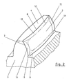
- FIG. 2 shows the prior art tooth 3 finished after the involute toothing, heat treatment and final grinding of the flank modifications.
- Dash-dotted lines 12 illustrate only the qualitative transitions of individual sections on the tooth flank and illustrate the different sub-areas with their transitions to one another. The exact position of the transitions on the tooth flank can only be determined with sensitive measuring instruments. A large part of the surface still forms the unmodified involute flank 2.
- the tooth flank is limited in height by the portions of the Kopschreibückanhme 13 and complicattechnischdging 14 and at the lateral edges of the areas of the flank line return 15.
- Fig. 3 is a section through two meshing teeth 16 and 17 shown with profile modification.
- the edge line 6 On the teeth along the edge line 6 as sections of the principal Vietnamese 10, the principalausrundung 9, the foot edge 11, the involute flank 2 and the tip circle edge 8 are shown.
- the dashed line shows the foot return 14 and the tooth head the linear head withdrawal 13. These modifications were removed by the teeth grinding.
- the contact between the teeth in the cutout X only has a recognizable gap 18 in the drawing, in order to make it clear that there is an oil film (not shown) between the supporting flanks.
- Fig. 4 shows as a section X the contact area of two teeth 16 and 17.
- the head return 13 are separated from the tooth by the grinding wheel larger amounts of the tooth material.
- a burr 19 may arise, which is greater than the normal tooth roughness.
- the z. B. off of the EP 0 414 441 A2 known and initially described chemically accelerated vibratory finishing performed.
- the gears are treated chemically and mechanically within a vibrated container with a special chemical fluid mixed with non-abrasive solids.
- the burrs 19, 20 and the discontinuity at point 21, which are caused by the introduction of the profile modification at the transitions of the adjoining flank edges of top circle 8 and bottom edge 9, are removed in repeated steps.
Abstract
Description
Die Erfindung betrifft ein Verfahren zur Fertigung von evolventenförmigen Verzahnungen von Zahnrädern, insbesondere von Stirnrädern mit einer Profilmodifikation, mit den Merkmalen des Oberbegriffs des Anspruches 1.The invention relates to a method for producing involute toothings of gears, in particular spur gears with a profile modification, with the features of the preamble of claim 1.
Die Stirnräder mit Verzahnungen in Zahnradgetrieben übertragen die Drehbewegung von einem Antriebsstrang zu einem Abtriebsstrang und wandeln zudem die Drehzahlen der Stränge. Dabei berühren sich zwei gegenüberliegende Zahnflanken zweier Räder. Die kontinuierliche Drehung der Räder führt zu einer kontinuierlichen Änderung des geometrischen Orts der Berührung entlang der Eingriffslinie. Ebenso ändern sich kontinuierlich die beteiligten Teilbereiche der Flanken an der Übertragung vom Beginn des Eingriffs bis zur Trennung der Flanken. Nacheinander übertragen auf diese Weise alle am Umfang angeordneten Zähne einen Teil der Drehung.The spur gears with gears in gear transmits the rotational movement of a drive train to a power train and also convert the speeds of the strands. In this case, two opposite tooth flanks of two wheels touch. The continuous rotation of the wheels results in a continuous change in the geometric location of the touch along the engagement line. Likewise, the involved subareas of the flanks continuously change at the transmission from the beginning of the intervention to the separation of the flanks. Successively, in this way, all circumferentially spaced teeth transmit part of the rotation.
Die kontinuierliche Veränderung der geometrischen Parameter darf nicht zu einer periodisch veränderlichen Übersetzung führen. Insbesondere die Flankenform einer Evolvente kompensiert solche Veränderungen derart, dass die Übersetzung unabhängig von den zeitlich veränderlichen geometrischen Parametern konstant bleibt. Die Übersetzung des Getriebes hängt nur noch vom Verhältnis der Zähnezahlen ab. Darüber hinaus ermöglichen weitere vorteilhafte Eigenschaften einer sochen Geometrie eine flexible Anpassung an ähnliche Ausgangsbedingungen.The continuous change of the geometric parameters must not lead to a periodically variable translation. In particular, the edge shape of an involute compensates for such changes that the translation remains constant, regardless of the time-varying geometric parameters. The gear ratio depends only on the ratio of the number of teeth. In addition, further advantageous properties of such a geometry enable flexible adaptation to similar starting conditions.
Zur Erfüllung der Aufgabe der Übertragung von Drehbewegungen sind vielfältige Formen von evolventenförmigen Gerad- und Schrägverzahnungen, insbesondere für Stirnrad-, Kegelrad- und Planetengetriebe, bekannt. Besonders vorteilhaft an solchen Verzahnungen ist die einfache Herstellbarkeit.To fulfill the task of transmitting rotational movements are manifold forms of involute straight and Helical gears, in particular for spur, bevel and planetary gear known. Particularly advantageous to such gears is the ease of manufacture.
Als äußerst wirtschaftlich bei hohen Anforderungen an die Flankengüte hat sich das kontinuierliche Wälzfräsen durchgesetzt. Dabei schneidet ein Fräswerkzeug die Zähne mit den evolventenförmigen Flanken aus einem massiven Rohling heraus.Continuous hobbing has proven to be extremely economical with high demands on the flank quality. A milling tool cuts out the teeth with the involute flanks from a solid blank.
Stahlwerkstoffe für Stirnräder bieten hier neben hohen Festigkeitswerten den besonderen Vorteil, dass sich die Festigkeitswerte mittels einer Wärmebehandlung für die Fertigung auf einen niedrigen Wert und für die anschließende Verwendung in Getrieben auf einen hohen Wert einstellen lassen. Für die abschließende Erhöhung der Festigkeitswerte eignen sich die Fertigungsverfahren Vergüten, Nitrieren oder Einsatzhärten. Die Gefügeumwandlung im Werkstoff bei der Wärmebehandlung führt unter anderem zu einem Verzug, d. h. zu einer Abweichung von der idealen geometrischen Flankenform. Zusätzlich können von der Schneide des Werkzeugs weitere Fertigungsspuren als Abweichungen von der idealen Evolvente auf der Oberfläche verbleiben. Insgesamt ist die Oberfläche durch relativ hohe Rauheitswerte mit einer unregelmäßigen rilligen Struktur gekennzeichnet. Die charakteristischen Rauheitswerte als Maß für die Summe der Abweichungen von der idealen geometrischen Flankenform sind in der Regel bei industrieüblichen Fertigungsverfahren größer als Ra = 12,5 µm.In addition to high strength values, steel materials for helical gears offer the particular advantage here of being able to set the strength values to a low value by means of a heat treatment for production and to a high value for subsequent use in transmissions. For the final increase in the strength values, the manufacturing processes tempering, nitriding or case hardening are suitable. The microstructure transformation in the material during the heat treatment leads inter alia to a delay, d. H. to a deviation from the ideal geometric edge shape. In addition, further production traces may remain on the surface as deviations from the ideal involute from the cutting edge of the tool. Overall, the surface is characterized by relatively high roughness values with an irregular grooved structure. The characteristic roughness values as a measure of the sum of the deviations from the ideal geometric flank shape are generally greater than Ra = 12.5 μm in industry-standard manufacturing processes.
Die Abweichungen auf der tatsächlichen Flankenoberfläche bestimmen die Verzahnungsqualität. Aus der Festigkeitslehre ist bekannt, dass an hoch beanspruchten Bauteilen raue Oberflächen infolge der Kerbwirkung zu einem vorzeitigen Versagen führen. Die einschlägigen Berechnungsmethoden berücksichtigen diesen Sachverhalt und streben aus diesem Grund eine möglichst hohe Verzahnungsqualität mit geringen Rauheitswerten zwischen Ra = 0,8 bis 1,6 µm an. Eine solche Güte lässt sich in einem weiteren Arbeitsschritt nach dem Fräsen und Härten durch das Schleifen oder Läppen erzielen. Eine darüber hinausgehende Verringerung der Oberflächengüte lässt sich nur mit erheblich längeren Bearbeitungszeiten erreichen. Dabei besteht die Gefahr, dass die zulässigen Temperaturen zwischen der rotierenden Schleifscheibe und Zahnflanke überschritten werden und zu Spannungsrissen oder durch lokales Anlassen zu einer Erweichung der Oberfläche führen. Ein solcher Effekt wird auch als Schleifbrand bezeichnet.The deviations on the actual flank surface determine the quality of the teeth. From the theory of strength is known that on highly stressed components rough surfaces due to the notch effect lead to premature failure. The relevant calculation methods take this fact into account and for this reason strive for the highest possible level Gear quality with low roughness values between Ra = 0.8 to 1.6 μm. Such quality can be achieved in a further step after milling and hardening by grinding or lapping. A further reduction of the surface quality can only be achieved with considerably longer processing times. There is a risk that the permissible temperatures between the rotating grinding wheel and the tooth flank are exceeded and lead to stress cracks or local tempering to a softening of the surface. Such an effect is also called grinding burn.
Die
Bei dem Verfahren des chemisch beschleunigten Gleitschleifens nach
Die
Dem entsprechend verzichtet die
Aus der
Die bekannten Verfahren zur Glättung der Flanken durch die Oberflächenfeinbearbeitung des chemisch beschleunigten Gleitschleifens haben den entscheidenden Nachteil, dass ausschließlich nur ein gleichmäßiger, wenige Mikrometer betragender dünner Abtrag über die gesamte Oberfläche erfolgt. Flankenformfehler, die als Verzug bei der Wärmebehandlung mit lokal unterschiedlichen Beträgen auftreten können und größer sind als die genannten Abtragsraten, lassen sich nur glätten, aber nicht zielgerichtet lokal entfernen. Insbesondere der vollständige Verzicht auf die Schleifbearbeitung gemäß der
Eine wichtige bekannte Schwierigkeit bei der Gestaltung der idealen Flankenform bei hoch belasteten Verzahnungen ist die Berücksichtigung der elastischen Verformung der Zähne unter der Betriebslast. Insbesondere an Stellen, an denen am Beginn oder Ende des Eingriffs von zwei gleichzeitig kämmenden Zahnpaaren zu nur einem kämmenden Zahnpaar übergegangen wird, ändert sich die spezifische Zahnbelastung und damit auch die elastische Verformung sprungförmig. Die Eingriffsstörungen treten am Zahnkopf bzw. Zahnfuß auf. Darüber hinaus verformt sich unter Last der gesamte Wellenstrang, so dass es auch über der Zahnbreite zu einem unterschiedlichen elastizitätsbedingten Tragbild kommt.An important well-known difficulty in designing the ideal flank shape for heavily loaded gears is the consideration of the elastic deformation of the teeth under the operating load. In particular, in places where at the beginning or end of the intervention of two simultaneously meshing tooth pairs to only one intermeshing tooth pair is passed, the specific tooth load and thus also the elastic deformation changes abruptly. The intervention disorders occur at the tooth tip or tooth root. In addition, under load deforms the entire shaft strand, so that there is also over the tooth width to a different elasticity-related contact pattern.
Solche Verformungen lassen sich vorab rechnerisch bestimmen und können durch lokal begrenzte Modifikationen am idealen Evolventenprofil ausgeglichen werden. Die Korrekturwerte betragen in Abhängigkeit vom Modul im Mittel 10 bis 50 µm und liegen mit einer Zehnerpotenz deutlich höher über den Werten, die mit dem chemisch beschleunigten Gleitschleifen erreichbar sind. Zudem erfolgen die Korrekturrücknahmen mit definiert zunehmenden Abtragsraten in Form von linearen oder parabolischen Kurvenbahnen. Solche begrenzten und örtlich veränderlichen Abtragsraten können nicht mit dem gleichmäßig äquidistanten Abtrag des Gleitschleifens hergestellt werden.Such deformations can be determined in advance by calculation and can be compensated by locally limited modifications to the ideal involute profile. Depending on the modulus, the correction values are on
Durch das Schleifen der Zahnflanke mit einer rotierenden Schleifscheibe lassen sich die Abweichungen aus der Fertigung und die berechneten lokalen Modifikationen definiert auf die Zahnflanken bringen. Die gewünschten Abtragsraten lassen sich über den Vorschub von Werkzeug und Werkstück steuern. Die Flächen der Rücknahmen weisen im Gegensatz zur Evolventenflanke eine andere räumliche Wölbung auf. Der Übergang zwischen den aneinandergrenzenden Teilflächen der Zahnflanke ist als unerwünschte Kantenlinie messtechnisch nachweisbar. Eine solche Kante wirkt sich in einer ölgeschmierten Wälzpaarung zweier Zahnflanken aufgrund des scharfkantigen Charakters nachteilig auf die hydrodynamischen Schmierverhältnisse aus. Ebenso nachteilig entsteht am radialen und stirnseitigen Austritt der Schleifscheibe aus dem Werkstück ein weiterer erkennbarer Grat, der zu Beschädigungen an der Gegenflanke führen kann.By grinding the tooth flank with a rotating grinding wheel, the deviations from the production and the calculated local modifications can be defined on the tooth flanks. The desired removal rates can be controlled via the feed of tool and workpiece. The areas of the reductions, in contrast to the involute flank, have a different spatial curvature. The transition between the adjoining partial surfaces of the tooth flank can be detected by measurement as an unwanted edge line. Such an edge has an adverse effect on the hydrodynamic lubrication conditions in an oil-lubricated pairing of two tooth flanks due to the sharp-edged character. Likewise disadvantageous arises at the radial and frontal outlet of the grinding wheel from the workpiece, a further recognizable ridge, which can lead to damage to the opposite flank.
Der Erfindung liegt die Aufgabe zugrunde, das gattungsgemäße Verfahren zur Fertigung einer Evolventenverzahnung mit Profilmodifikation so zu gestalten, dass an dem Übergang von der idealen Evolventenflanke zu den modifizierten Flächenstücken asymptotisch kein erkennbarer Grat verbleibt.The invention has for its object to make the generic method for producing an involute with profile modification so that asymptotically no recognizable ridge remains at the transition from the ideal involute flank to the modified surface pieces.
Die Aufgabe der Erfindung wird bei einem gattungsgemäßen Verfahren erfindungsgemäß durch die kennzeichnenden Merkmale des Anspruchs 1 gelöst. Vorteilhafte Ausgestaltungen der Erfindung sind Gegenstand der Unteransprüche.The object of the invention is achieved according to the invention in a generic method by the characterizing features of claim 1. Advantageous embodiments of the invention are the subject of the dependent claims.
Ein außen- oder innenverzahntes Zahnrad wird mit einer gewissen Bearbeitungszugabe durch Wälzfräsen hergestellt. Eine anschließende für den jeweiligen Werkstoff geeignete Wärmebehandlung erhöht die Festigkeitswerte der Verzahnung. Die Oberfläche der harten Zahnflanke wird mittels einer rotierenden Schleifscheibe abschließend in Form und Oberflächengüte fein bearbeitet. Auf eine umständliche Kantenverrundung durch die Werkzeugführung kann verzichtet werden und führt zu einer Verkürzung der Bearbeitungsdauer. Damit reduziert sich auch die Gefahr der Schleifbrandbildung.An externally or internally toothed gear is produced with a certain machining allowance by hobbing. A subsequent heat treatment suitable for the respective material increases the strength values of the toothing. The surface of the hard tooth flank is finely finished by means of a rotating grinding wheel in shape and surface quality processed. An awkward edge rounding by the tool guide can be dispensed with and leads to a shortening of the processing time. This also reduces the risk of grinding burns.
Die verzahnten und flankenmodifizierten Zahnräder werden im Unterschied zum Stand der Technik in einem letzten Bearbeitungsschritt mit dem bekannten chemisch beschleunigten Gleitschleifen behandelt.The toothed and flank-modified gears are treated in contrast to the prior art in a final processing step with the known chemically accelerated vibratory finishing.
Eine an die Bauteilgeometrie und Behandlungsziele angepasste Prozessführung führt zunächst durch die Schleifwirkung der nicht abrasiven Feststoffe zu einem vorrangigen Abtrag der Grate an den Flankenrändern und einer asymptotischen Nivellierung der Kanten in der Zahnflanke zwischen benachbarten Flächenstücken. Die unerwünschten Oberflächenfehler werden solange durch die festen Schleifsubstanzen unmittelbar entfernt, bis die Größenverhältnisse zwischen den schleifenden Feststoffen und dem überzähligen Material eine bestimmte Größe unterschreiten.A process control adapted to the component geometry and treatment objectives initially leads, by the abrasive action of the non-abrasive solids, to a predominant removal of the burrs at the edge edges and an asymptotic leveling of the edges in the tooth flank between adjacent surface pieces. The unwanted surface defects are removed by the solid abrasive substances until the size ratios between the abrasive solids and the surplus material fall below a certain size.
Erst ab dem Punkt der Unterschreitung der vorbestimmten Größe des überzähligen Materials unterstützt die chemische Spezialflüssigkeit den Trennvorgang, indem die verbliebenen Erhebungsreste von der Substanz fortwährend ummantelt werden. Ein solcher Effekt ermöglicht den Schleifkörpern die Fortsetzung des Glättungsvorgangs. Zeitgleich zur Behandlung der Kanten werden auch auf allen Bauteiloberflächen die Rauheitsspitzen als Folge der Wechselwirkung zwischen den Spitzen, der Spezialflüssigkeit und den Schleifkörpern entfernt. Nach Abschluss der Behandlung weist die Oberfläche Rauheitswerte von Ra = 0,3 - 0,4 µm auf.Only from the point of falling below the predetermined size of the surplus material, the special chemical liquid supports the separation process by the remainder of the survey remains are coated by the substance continuously. Such an effect allows the abrasives to continue the smoothing process. Simultaneously with the treatment of the edges, the roughness peaks on all component surfaces are removed as a result of the interaction between the tips, the special liquid and the abrasive bodies. After completion of the treatment, the surface has roughness values of Ra = 0.3-0.4 μm.
Die Erfindung und die mit der Erfindung verbundenen Vorteile werden nachfolgend an einem in der Zeichnung dargestellten Ausführungsbeispiel näher erläutert. Es zeigen:
- Fig. 1
- einen Ausschnitt auf eine Verzahnung mit Evolventenflanken nach dem Stand der Technik,
- Fig. 2
- eine Ansicht auf eine modifizierte Verzahnung nach der Erfindung,
- Fig. 3
- eine Ansicht eines kämmenden Zahnpaares,
- Fig. 4
- einen vergrößerten Ausschnitt auf den Zahneingriff.
- Fig. 1
- a detail of a toothing with involute flanks according to the prior art,
- Fig. 2
- a view of a modified toothing according to the invention,
- Fig. 3
- a view of a combing tooth pair,
- Fig. 4
- an enlarged section on the tooth mesh.
Fig. 1 zeigt einen Ausschnitt auf eine Verzahnung 1 mit Evolventenflanken 2 nach dem Stand der Technik. Zur Verdeutlichung des bekannten Ausführungsbeispiels sind die Darstellungen auf den wesentlichen Informationsgehalt reduziert. Die eingezeichneten Verhältnisse sind lediglich zur deutlichen Erklärung nicht maßstabsgetreu vergrößert wiedergegeben.Fig. 1 shows a section of a toothing 1 with
Von einem nicht dargestellten Wälzfräser werden Zähne 3 in einem kontinuierlichen Schneidvorgang aus einem massiven vorbearbeiteten zylindrischen Rohling herausgearbeitet. Ein Kopfkreis 4 und Stirnseiten 5 sowie nicht dargestellte Spannbohrungen sind in einer vorgeschalteten Bearbeitungsstation mit den vorgegebenen Konstruktionsmaßen hergestellt worden. Das Fräswerkzeug erzeugt zwischen den Zähnen den Freiraum, der von einer Kantenlinie 6 begrenzt ist.From a hob, not shown,
Die Kantenlinie 6 setzt sich aus mehreren Abschnitten zusammen. An einer ersten Zahnflanke beginnt die ideale Kurve einer Evolvente 7 an einer Kopfkreiskante 8 und führt zu einer Fußausrundung 9, die wiederum in einen Fußkreis 10 übergeht. An der rückwärtigen Flanke des benachbarten Zahns setzt sich die Kantenlinie 6 in der gleichen Weise fort.The
In Abhängigkeit von den Verzahnungsdaten kann das Fräswerkzeug die Fußausrundung 9 so gestalten, dass ein Fußfreischnitt mit einer ausgeprägten Fußkante 11 als Übergang zur Evolventenflanke 2 entsteht. Vorteilhafterweise lässt sich der Überstand der Evolventenflanke 2 gegenüber der Fußausrundung 9 als Bearbeitungszugabe für die nachfolgende Schleifbearbeitung nutzen. Insbesondere lässt sich dadurch eine weitere Schleifkerbe durch die verwendete Schleifscheibe im Zahnfuß verhindern. Andere gezielte Modifikationen an der Verzahnung lassen sich mit dem Wälzfräsen nicht herstellen.Depending on the gear data, the
Fig. 2 zeigt den Zahn 3 nach dem Stand der Technik, der nach dem Fräsen der Evolventenverzahnung, einer Wärmebehandlung und einem abschließenden Schleifen der Flankenmodifikationen fertig bearbeitet ist. Strichpunktierte Linien 12 illustrieren nur die qualitativen Übergänge einzelner Abschnitte auf der Zahnflanke und verdeutlichen die unterschiedlichen Teilflächen mit ihren Übergängen zueinander. Die genaue Lage der Übergänge auf der Zahnflanke lässt sich nur mit empfindlichen Meßgeräten bestimmen. Einen großen Teil der Fläche bildet immer noch die nicht modifizierte Evolventenflanke 2. Die Zahnflanke wird in der Höhe von den Abschnitten der Kopfrückanhme 13 und Fußrücknahme 14 und an den seitlichen Rändern von den Bereichen der Flankenlinienrücknahme 15 begrenzt.FIG. 2 shows the
In Fig. 3 ist ein Schnitt durch zwei miteinander kämmende Zähne 16 und 17 mit Profilmodifikation dargestellt. An den Zähnen sind entlang der Kantenlinie 6 als Teilabschnitte der Fußkreis 10, die Fußausrundung 9, die Fußkante 11, die Evolventenflanke 2 und die Kopfkreiskante 8 dargestellt. Im Fußbereich zeigt die gestrichelte Linie die Fußrücknahme 14 und am Zahnkopf die lineare Kopfrücknahme 13. Diese Modifikationen wurden durch das Zahnschleifen abgetragen. Der Kontakt zwischen den Zähnen im Ausschnitt X weist nur zeichnerisch einen erkennbaren Spalt 18 auf, um zu verdeutlichen, dass sich zwischen den tragenden Flanken ein nicht dargestellter Ölfilm befindet.In Fig. 3 is a section through two meshing
Fig. 4 zeigt als Ausschnitt X den Kontaktbereich zweier Zähne 16 und 17. Durch die Kopfrücknahme 13 werden von dem Zahn durch die Schleifscheibe größere Mengen des Zahnwerkstoffs abgetrennt. Insbesondere am Scheibenauslauf zum Kopfkreis 8 kann ein Grat 19 entstehen, der größer als die normale Zahnrauhigkeit ist. Durch die Vorschubsteuerung der Schleifscheibe wird zwar häufig eine Verrundung angestrebt, die aber zu einer unwirtschaftlichen Erhöhung der Bearbeitungsdauer führt. Ebenso kann am unteren Auslauf an der Fußkante 11 eine weitere Gratbildung 20 beobachtet werden.Fig. 4 shows as a section X the contact area of two
Die lineare Kopfrücknahme geht in einem Punkt 21 in die Evolventenflanke 2 über. In dem Spalt 18 bildet sich durch das anwesende Schmieröl ein tragender hydrodynamischer Schmierfilm aus. Aus Überlegungen zur Theorie der Hydrodynamik lässt sich folgern, dass schon kleine Unstetigkeiten in der Wandrauhigkeit, wie hier im Punkt 21, erhebliche Störungen in dem Strömungszustand eines Schmierfilms bewirken.The linear tip retraction merges into the
Die Auswirkungen sowohl der Gratbildung 19 und 20 und die Störung in dem Schmierfilm werden bei normaler industrieüblicher Belastung von anderen Einflüssen überdeckt. Gerade bei Verzahnungen für höchste Belastungen in Getrieben für Windkraftanlagen sind diese Fehlerquellen mit hoher Sicherheit auszuschalten. Die hier übliche Paarung von einsatzgehärteten Planetenverzahnungen und dazu weicheren vergüteten Hohlrädern kann zu einer Beschädigung mit abrasivem Verschleiß der Flankenflächen 2 führen. Die relativ geringen Drehzahlen erfordern zudem besondere Maßnahmen zur sicheren Ausbildung des Schmierfilms zwischen den Flanken.The effects of both
Im Anschluss an das Schleifen der flankenmodifizierten Verzahnung wird als letzter Bearbeitungsschritt das z. B. aus der
Claims (2)
Priority Applications (4)
| Application Number | Priority Date | Filing Date | Title |
|---|---|---|---|
| ES06004800T ES2314766T3 (en) | 2006-03-09 | 2006-03-09 | PROCESS FOR THE MANUFACTURE OF ENGAGEMENT WHEELS OF GEAR WHEELS |
| DE502006001676T DE502006001676D1 (en) | 2006-03-09 | 2006-03-09 | Method for producing involute gear teeth of gears |
| EP06004800A EP1832370B1 (en) | 2006-03-09 | 2006-03-09 | Process of manufacturing involute gear tooth system |
| AT06004800T ATE409540T1 (en) | 2006-03-09 | 2006-03-09 | METHOD FOR PRODUCING EVOLVE-SHAPED GEARS OF GEARS |
Applications Claiming Priority (1)
| Application Number | Priority Date | Filing Date | Title |
|---|---|---|---|
| EP06004800A EP1832370B1 (en) | 2006-03-09 | 2006-03-09 | Process of manufacturing involute gear tooth system |
Publications (2)
| Publication Number | Publication Date |
|---|---|
| EP1832370A1 true EP1832370A1 (en) | 2007-09-12 |
| EP1832370B1 EP1832370B1 (en) | 2008-10-01 |
Family
ID=36570771
Family Applications (1)
| Application Number | Title | Priority Date | Filing Date |
|---|---|---|---|
| EP06004800A Active EP1832370B1 (en) | 2006-03-09 | 2006-03-09 | Process of manufacturing involute gear tooth system |
Country Status (4)
| Country | Link |
|---|---|
| EP (1) | EP1832370B1 (en) |
| AT (1) | ATE409540T1 (en) |
| DE (1) | DE502006001676D1 (en) |
| ES (1) | ES2314766T3 (en) |
Cited By (8)
| Publication number | Priority date | Publication date | Assignee | Title |
|---|---|---|---|---|
| WO2010132914A1 (en) * | 2009-05-20 | 2010-11-25 | Miba Sinter Austria Gmbh | Gear wheel |
| WO2013054166A1 (en) * | 2011-10-11 | 2013-04-18 | Toyota Jidosha Kabushiki Kaisha | Toothed wheels and transmission |
| WO2016088577A1 (en) * | 2014-12-05 | 2016-06-09 | 株式会社エンプラス | Resin helical gear |
| JP2016109289A (en) * | 2014-12-05 | 2016-06-20 | 株式会社エンプラス | Resin helical gear |
| WO2017013344A1 (en) * | 2015-07-20 | 2017-01-26 | Valeo Equipements Electriques Moteur | Motor-vehicle starter provided with breaks on the pinion teeth |
| CN106481780A (en) * | 2016-10-12 | 2017-03-08 | 湖南工业大学 | A kind of face polishing gear edge by use height and tip relief method for determination of amount |
| EP3387294A4 (en) * | 2015-12-11 | 2019-07-17 | Gear Innovations LLC | Conjugate gears with continuous tooth flank contact |
| US11054013B1 (en) * | 2021-01-08 | 2021-07-06 | Enplas Corporation | Profile modification for planetary gear device gear teeth |
Families Citing this family (4)
| Publication number | Priority date | Publication date | Assignee | Title |
|---|---|---|---|---|
| DE102012112973B4 (en) * | 2012-12-21 | 2023-08-24 | Dr. Ing. H.C. F. Porsche Aktiengesellschaft | Motor vehicle with purely electric drive |
| CN107025367B (en) * | 2017-06-05 | 2019-08-23 | 太原理工大学 | Spur gear wheel profile modification method based on gear teeth thermoelastic distortion and gear diagonal distortion |
| DE102020131402A1 (en) | 2020-11-26 | 2022-06-02 | Bundesrepublik Deutschland, Vertreten Durch Das Bundesministerium Für Wirtschaft Und Energie, Dieses Vertreten Durch Den Präsidenten Der Physikalisch-Technischen Bundesanstalt | Method for producing a shape deviation standard and shape deviation standard |
| EP4310315A1 (en) * | 2022-07-21 | 2024-01-24 | MAHLE International GmbH | Starter device and internal combustion engine having the same |
Citations (5)
| Publication number | Priority date | Publication date | Assignee | Title |
|---|---|---|---|---|
| EP0229894A2 (en) * | 1985-12-13 | 1987-07-29 | Werkzeugmaschinenfabrik Oerlikon-Bührle AG | Method for grinding the toothing of bevel gears having teeth curved in their longitudinal direction as well as tool and device for carrying out the method |
| EP0414441A2 (en) | 1989-08-23 | 1991-02-27 | Rem Chemicals, Inc. | Burnishing method and composition |
| EP1167825A2 (en) | 2000-06-30 | 2002-01-02 | Eaton Corporation | Polished gear surfaces |
| EP1350601A1 (en) * | 2002-04-02 | 2003-10-08 | Winergy AG | Method for treating gears |
| WO2004108356A1 (en) | 2003-05-30 | 2004-12-16 | Rem Technologies, Inc. | Superfinishing large planetary gear systems |
-
2006
- 2006-03-09 ES ES06004800T patent/ES2314766T3/en active Active
- 2006-03-09 AT AT06004800T patent/ATE409540T1/en not_active IP Right Cessation
- 2006-03-09 EP EP06004800A patent/EP1832370B1/en active Active
- 2006-03-09 DE DE502006001676T patent/DE502006001676D1/en active Active
Patent Citations (6)
| Publication number | Priority date | Publication date | Assignee | Title |
|---|---|---|---|---|
| EP0229894A2 (en) * | 1985-12-13 | 1987-07-29 | Werkzeugmaschinenfabrik Oerlikon-Bührle AG | Method for grinding the toothing of bevel gears having teeth curved in their longitudinal direction as well as tool and device for carrying out the method |
| EP0414441A2 (en) | 1989-08-23 | 1991-02-27 | Rem Chemicals, Inc. | Burnishing method and composition |
| EP1167825A2 (en) | 2000-06-30 | 2002-01-02 | Eaton Corporation | Polished gear surfaces |
| EP1350601A1 (en) * | 2002-04-02 | 2003-10-08 | Winergy AG | Method for treating gears |
| EP1350601B1 (en) | 2002-04-02 | 2004-09-08 | Winergy AG | Method for treating gears |
| WO2004108356A1 (en) | 2003-05-30 | 2004-12-16 | Rem Technologies, Inc. | Superfinishing large planetary gear systems |
Cited By (16)
| Publication number | Priority date | Publication date | Assignee | Title |
|---|---|---|---|---|
| US9291248B2 (en) | 2009-05-20 | 2016-03-22 | Miba Sinter Austria Gmbh | Gear wheel |
| WO2010132914A1 (en) * | 2009-05-20 | 2010-11-25 | Miba Sinter Austria Gmbh | Gear wheel |
| WO2013054166A1 (en) * | 2011-10-11 | 2013-04-18 | Toyota Jidosha Kabushiki Kaisha | Toothed wheels and transmission |
| CN103857943A (en) * | 2011-10-11 | 2014-06-11 | 丰田自动车株式会社 | Toothed wheels and transmission |
| AU2012322472B2 (en) * | 2011-10-11 | 2015-12-03 | Toyota Jidosha Kabushiki Kaisha | Toothed wheels and transmission |
| CN103857943B (en) * | 2011-10-11 | 2016-10-19 | 丰田自动车株式会社 | Gear and variator |
| US10584784B2 (en) | 2014-12-05 | 2020-03-10 | Enplas Corporation | Resin helical gear |
| WO2016088577A1 (en) * | 2014-12-05 | 2016-06-09 | 株式会社エンプラス | Resin helical gear |
| JP2016109289A (en) * | 2014-12-05 | 2016-06-20 | 株式会社エンプラス | Resin helical gear |
| WO2017013344A1 (en) * | 2015-07-20 | 2017-01-26 | Valeo Equipements Electriques Moteur | Motor-vehicle starter provided with breaks on the pinion teeth |
| FR3039223A1 (en) * | 2015-07-20 | 2017-01-27 | Valeo Equip Electr Moteur | MOTOR VEHICLE STARTER GEAR WITH DECROCHEMENT |
| EP3387294A4 (en) * | 2015-12-11 | 2019-07-17 | Gear Innovations LLC | Conjugate gears with continuous tooth flank contact |
| US10527149B2 (en) | 2015-12-11 | 2020-01-07 | Gear Innovations Llc | Conjugate gears with continuous tooth flank contact |
| CN106481780A (en) * | 2016-10-12 | 2017-03-08 | 湖南工业大学 | A kind of face polishing gear edge by use height and tip relief method for determination of amount |
| CN106481780B (en) * | 2016-10-12 | 2018-11-27 | 湖南工业大学 | A kind of face gear tip relief height and tip relief method for determination of amount |
| US11054013B1 (en) * | 2021-01-08 | 2021-07-06 | Enplas Corporation | Profile modification for planetary gear device gear teeth |
Also Published As
| Publication number | Publication date |
|---|---|
| ES2314766T3 (en) | 2009-03-16 |
| ATE409540T1 (en) | 2008-10-15 |
| EP1832370B1 (en) | 2008-10-01 |
| DE502006001676D1 (en) | 2008-11-13 |
Similar Documents
| Publication | Publication Date | Title |
|---|---|---|
| EP1832370B1 (en) | Process of manufacturing involute gear tooth system | |
| DE69735631T2 (en) | APPARATUS AND METHOD FOR PRECISION GRINDING CROWN WHEELS | |
| DE69916120T2 (en) | METHOD FOR POST-OPERATING GEARS AND GEAR | |
| DE10393256B4 (en) | Planetary gear set with multi-layer coated sun gear | |
| DE102010006094B4 (en) | Process for surface hardening a component of a wind turbine | |
| DE102009059201B4 (en) | Solid profile roller for dressing multi-start cylindrical grinding worms | |
| EP3325203B1 (en) | Method for honing gears | |
| EP2402631B1 (en) | Planetary gear for a main loading direction | |
| EP2929970B1 (en) | Method for grinding of a workpiece with a grinding worm | |
| EP3999270B1 (en) | Method for grinding a gear wheel by means of a worm grinding wheel, and a dressing roll for dressing the worm grinding wheel | |
| DE102019115294B4 (en) | Process for the production of a workpiece provided with a toothing or profiling | |
| DE102017126988A1 (en) | Tool, machine and method for the smooth rolling of toothed workpieces | |
| CH658619A5 (en) | TOOL FOR THE PRODUCTION OF EXTERNAL PROFILE FORMS. | |
| WO1996035543A1 (en) | Method of finishing the hardened teeth of a bevel gear wheel | |
| EP3756809A1 (en) | Method for producing a toothing component and a toothing grinding machine | |
| WO2021180633A1 (en) | Method for hob-machining a gear wheel | |
| DE102021108382A1 (en) | PROCESS FOR CREATING SETTINGS ON THE GEAR FLANKS OF AN INTERNALLY GEARED WORKPIECE | |
| DE3508065A1 (en) | METHOD AND SYSTEM FOR IMPROVING THE SURFACE ACCURACY AND QUALITY OF CURVED TEETH | |
| DE102020204380A1 (en) | METHOD OF GRINDING WORKPIECES WITH A SCREW-SHAPED PROFILE AND GRINDING MACHINE FOR MANUFACTURING SUCH WORKPIECES | |
| WO2021001055A1 (en) | Method for producing tooth flank modifications on toothing of workpieces and tools for performing said method | |
| EP0815984A1 (en) | Method and device for finishing the tooth flanks of a gear wheel on a machine tool | |
| EP3867007A1 (en) | Method for producing a gear worm which is located in particular on an armature shaft, and such a gear worm | |
| WO2019110519A1 (en) | Method for producing a gear wheel | |
| DE102017217933A1 (en) | Method and device for producing a gear component of a transmission, in particular a wind power planetary gear | |
| DE19650350C2 (en) | Tool and method for spinning a workpiece with teeth |
Legal Events
| Date | Code | Title | Description |
|---|---|---|---|
| PUAI | Public reference made under article 153(3) epc to a published international application that has entered the european phase |
Free format text: ORIGINAL CODE: 0009012 |
|
| 17P | Request for examination filed |
Effective date: 20070404 |
|
| AK | Designated contracting states |
Kind code of ref document: A1 Designated state(s): AT BE BG CH CY CZ DE DK EE ES FI FR GB GR HU IE IS IT LI LT LU LV MC NL PL PT RO SE SI SK TR |
|
| AX | Request for extension of the european patent |
Extension state: AL BA HR MK YU |
|
| GRAP | Despatch of communication of intention to grant a patent |
Free format text: ORIGINAL CODE: EPIDOSNIGR1 |
|
| AKX | Designation fees paid |
Designated state(s): AT BE BG CH CY CZ DE DK EE ES FI FR GB GR HU IE IS IT LI LT LU LV MC NL PL PT RO SE SI SK TR |
|
| GRAS | Grant fee paid |
Free format text: ORIGINAL CODE: EPIDOSNIGR3 |
|
| GRAA | (expected) grant |
Free format text: ORIGINAL CODE: 0009210 |
|
| AK | Designated contracting states |
Kind code of ref document: B1 Designated state(s): AT BE BG CH CY CZ DE DK EE ES FI FR GB GR HU IE IS IT LI LT LU LV MC NL PL PT RO SE SI SK TR |
|
| REG | Reference to a national code |
Ref country code: GB Ref legal event code: FG4D Free format text: NOT ENGLISH |
|
| REG | Reference to a national code |
Ref country code: CH Ref legal event code: EP |
|
| REG | Reference to a national code |
Ref country code: IE Ref legal event code: FG4D Free format text: LANGUAGE OF EP DOCUMENT: GERMAN |
|
| REF | Corresponds to: |
Ref document number: 502006001676 Country of ref document: DE Date of ref document: 20081113 Kind code of ref document: P |
|
| PG25 | Lapsed in a contracting state [announced via postgrant information from national office to epo] |
Ref country code: SI Free format text: LAPSE BECAUSE OF FAILURE TO SUBMIT A TRANSLATION OF THE DESCRIPTION OR TO PAY THE FEE WITHIN THE PRESCRIBED TIME-LIMIT Effective date: 20081001 |
|
| REG | Reference to a national code |
Ref country code: ES Ref legal event code: FG2A Ref document number: 2314766 Country of ref document: ES Kind code of ref document: T3 |
|
| NLV1 | Nl: lapsed or annulled due to failure to fulfill the requirements of art. 29p and 29m of the patents act | ||
| REG | Reference to a national code |
Ref country code: IE Ref legal event code: FD4D |
|
| PG25 | Lapsed in a contracting state [announced via postgrant information from national office to epo] |
Ref country code: LT Free format text: LAPSE BECAUSE OF FAILURE TO SUBMIT A TRANSLATION OF THE DESCRIPTION OR TO PAY THE FEE WITHIN THE PRESCRIBED TIME-LIMIT Effective date: 20081001 Ref country code: BG Free format text: LAPSE BECAUSE OF FAILURE TO SUBMIT A TRANSLATION OF THE DESCRIPTION OR TO PAY THE FEE WITHIN THE PRESCRIBED TIME-LIMIT Effective date: 20090101 |
|
| PG25 | Lapsed in a contracting state [announced via postgrant information from national office to epo] |
Ref country code: NL Free format text: LAPSE BECAUSE OF FAILURE TO SUBMIT A TRANSLATION OF THE DESCRIPTION OR TO PAY THE FEE WITHIN THE PRESCRIBED TIME-LIMIT Effective date: 20081001 Ref country code: LV Free format text: LAPSE BECAUSE OF FAILURE TO SUBMIT A TRANSLATION OF THE DESCRIPTION OR TO PAY THE FEE WITHIN THE PRESCRIBED TIME-LIMIT Effective date: 20081001 Ref country code: PT Free format text: LAPSE BECAUSE OF FAILURE TO SUBMIT A TRANSLATION OF THE DESCRIPTION OR TO PAY THE FEE WITHIN THE PRESCRIBED TIME-LIMIT Effective date: 20090302 Ref country code: IS Free format text: LAPSE BECAUSE OF FAILURE TO SUBMIT A TRANSLATION OF THE DESCRIPTION OR TO PAY THE FEE WITHIN THE PRESCRIBED TIME-LIMIT Effective date: 20090201 Ref country code: PL Free format text: LAPSE BECAUSE OF FAILURE TO SUBMIT A TRANSLATION OF THE DESCRIPTION OR TO PAY THE FEE WITHIN THE PRESCRIBED TIME-LIMIT Effective date: 20081001 |
|
| PG25 | Lapsed in a contracting state [announced via postgrant information from national office to epo] |
Ref country code: DK Free format text: LAPSE BECAUSE OF FAILURE TO SUBMIT A TRANSLATION OF THE DESCRIPTION OR TO PAY THE FEE WITHIN THE PRESCRIBED TIME-LIMIT Effective date: 20081001 Ref country code: EE Free format text: LAPSE BECAUSE OF FAILURE TO SUBMIT A TRANSLATION OF THE DESCRIPTION OR TO PAY THE FEE WITHIN THE PRESCRIBED TIME-LIMIT Effective date: 20081001 Ref country code: IE Free format text: LAPSE BECAUSE OF FAILURE TO SUBMIT A TRANSLATION OF THE DESCRIPTION OR TO PAY THE FEE WITHIN THE PRESCRIBED TIME-LIMIT Effective date: 20081001 Ref country code: RO Free format text: LAPSE BECAUSE OF FAILURE TO SUBMIT A TRANSLATION OF THE DESCRIPTION OR TO PAY THE FEE WITHIN THE PRESCRIBED TIME-LIMIT Effective date: 20081001 |
|
| PLBE | No opposition filed within time limit |
Free format text: ORIGINAL CODE: 0009261 |
|
| STAA | Information on the status of an ep patent application or granted ep patent |
Free format text: STATUS: NO OPPOSITION FILED WITHIN TIME LIMIT |
|
| PG25 | Lapsed in a contracting state [announced via postgrant information from national office to epo] |
Ref country code: CZ Free format text: LAPSE BECAUSE OF FAILURE TO SUBMIT A TRANSLATION OF THE DESCRIPTION OR TO PAY THE FEE WITHIN THE PRESCRIBED TIME-LIMIT Effective date: 20081001 Ref country code: SE Free format text: LAPSE BECAUSE OF FAILURE TO SUBMIT A TRANSLATION OF THE DESCRIPTION OR TO PAY THE FEE WITHIN THE PRESCRIBED TIME-LIMIT Effective date: 20090101 Ref country code: IT Free format text: LAPSE BECAUSE OF FAILURE TO SUBMIT A TRANSLATION OF THE DESCRIPTION OR TO PAY THE FEE WITHIN THE PRESCRIBED TIME-LIMIT Effective date: 20081001 |
|
| 26N | No opposition filed |
Effective date: 20090702 |
|
| PG25 | Lapsed in a contracting state [announced via postgrant information from national office to epo] |
Ref country code: SK Free format text: LAPSE BECAUSE OF FAILURE TO SUBMIT A TRANSLATION OF THE DESCRIPTION OR TO PAY THE FEE WITHIN THE PRESCRIBED TIME-LIMIT Effective date: 20081001 |
|
| PG25 | Lapsed in a contracting state [announced via postgrant information from national office to epo] |
Ref country code: MC Free format text: LAPSE BECAUSE OF NON-PAYMENT OF DUE FEES Effective date: 20090331 |
|
| PG25 | Lapsed in a contracting state [announced via postgrant information from national office to epo] |
Ref country code: AT Free format text: LAPSE BECAUSE OF NON-PAYMENT OF DUE FEES Effective date: 20090309 |
|
| PG25 | Lapsed in a contracting state [announced via postgrant information from national office to epo] |
Ref country code: GR Free format text: LAPSE BECAUSE OF FAILURE TO SUBMIT A TRANSLATION OF THE DESCRIPTION OR TO PAY THE FEE WITHIN THE PRESCRIBED TIME-LIMIT Effective date: 20090102 |
|
| REG | Reference to a national code |
Ref country code: CH Ref legal event code: PL |
|
| PG25 | Lapsed in a contracting state [announced via postgrant information from national office to epo] |
Ref country code: LI Free format text: LAPSE BECAUSE OF NON-PAYMENT OF DUE FEES Effective date: 20100331 Ref country code: CH Free format text: LAPSE BECAUSE OF NON-PAYMENT OF DUE FEES Effective date: 20100331 |
|
| PG25 | Lapsed in a contracting state [announced via postgrant information from national office to epo] |
Ref country code: LU Free format text: LAPSE BECAUSE OF NON-PAYMENT OF DUE FEES Effective date: 20090309 |
|
| PG25 | Lapsed in a contracting state [announced via postgrant information from national office to epo] |
Ref country code: HU Free format text: LAPSE BECAUSE OF FAILURE TO SUBMIT A TRANSLATION OF THE DESCRIPTION OR TO PAY THE FEE WITHIN THE PRESCRIBED TIME-LIMIT Effective date: 20090402 |
|
| PG25 | Lapsed in a contracting state [announced via postgrant information from national office to epo] |
Ref country code: TR Free format text: LAPSE BECAUSE OF FAILURE TO SUBMIT A TRANSLATION OF THE DESCRIPTION OR TO PAY THE FEE WITHIN THE PRESCRIBED TIME-LIMIT Effective date: 20081001 |
|
| PG25 | Lapsed in a contracting state [announced via postgrant information from national office to epo] |
Ref country code: CY Free format text: LAPSE BECAUSE OF FAILURE TO SUBMIT A TRANSLATION OF THE DESCRIPTION OR TO PAY THE FEE WITHIN THE PRESCRIBED TIME-LIMIT Effective date: 20081001 |
|
| PG25 | Lapsed in a contracting state [announced via postgrant information from national office to epo] |
Ref country code: DE Free format text: LAPSE BECAUSE OF NON-PAYMENT OF DUE FEES Effective date: 20111001 |
|
| REG | Reference to a national code |
Ref country code: DE Ref legal event code: R082 Ref document number: 502006001676 Country of ref document: DE |
|
| REG | Reference to a national code |
Ref country code: DE Ref legal event code: R081 Ref document number: 502006001676 Country of ref document: DE Owner name: SIEMENS AKTIENGESELLSCHAFT, DE Free format text: FORMER OWNER: WINERGY AG, 46562 VOERDE, DE Effective date: 20130625 Ref country code: DE Ref legal event code: R081 Ref document number: 502006001676 Country of ref document: DE Owner name: FLENDER GMBH, DE Free format text: FORMER OWNER: WINERGY AG, 46562 VOERDE, DE Effective date: 20130625 |
|
| REG | Reference to a national code |
Ref country code: GB Ref legal event code: 732E Free format text: REGISTERED BETWEEN 20131024 AND 20131030 |
|
| REG | Reference to a national code |
Ref country code: ES Ref legal event code: PC2A Owner name: SIEMENS AKTIENGESELLSCHAFT Effective date: 20131126 |
|
| REG | Reference to a national code |
Ref country code: FR Ref legal event code: TP Owner name: SIEMENS AKTIENGESELLSCHAFT, DE Effective date: 20131127 |
|
| REG | Reference to a national code |
Ref country code: FR Ref legal event code: PLFP Year of fee payment: 11 |
|
| REG | Reference to a national code |
Ref country code: FR Ref legal event code: PLFP Year of fee payment: 12 |
|
| REG | Reference to a national code |
Ref country code: DE Ref legal event code: R081 Ref document number: 502006001676 Country of ref document: DE Owner name: FLENDER GMBH, DE Free format text: FORMER OWNER: SIEMENS AKTIENGESELLSCHAFT, 80333 MUENCHEN, DE |
|
| REG | Reference to a national code |
Ref country code: ES Ref legal event code: PC2A Owner name: FLENDER GMBH Effective date: 20171219 |
|
| REG | Reference to a national code |
Ref country code: GB Ref legal event code: 732E Free format text: REGISTERED BETWEEN 20171207 AND 20171213 |
|
| REG | Reference to a national code |
Ref country code: BE Ref legal event code: PD Owner name: FLENDER GMBH; DE Free format text: DETAILS ASSIGNMENT: CHANGE OF OWNER(S), AFFECTATION / CESSION; FORMER OWNER NAME: SIEMENS AKTIENGESELLSCHAFT Effective date: 20171117 |
|
| REG | Reference to a national code |
Ref country code: FR Ref legal event code: PLFP Year of fee payment: 13 |
|
| REG | Reference to a national code |
Ref country code: FR Ref legal event code: TP Owner name: FLENDER GMBH, DE Effective date: 20180316 |
|
| REG | Reference to a national code |
Ref country code: DE Ref legal event code: R082 Ref document number: 502006001676 Country of ref document: DE Representative=s name: MICHALSKI HUETTERMANN & PARTNER PATENTANWAELTE, DE |
|
| PGFP | Annual fee paid to national office [announced via postgrant information from national office to epo] |
Ref country code: GB Payment date: 20220321 Year of fee payment: 17 Ref country code: FI Payment date: 20220322 Year of fee payment: 17 |
|
| PGFP | Annual fee paid to national office [announced via postgrant information from national office to epo] |
Ref country code: FR Payment date: 20220322 Year of fee payment: 17 Ref country code: BE Payment date: 20220321 Year of fee payment: 17 |
|
| PGFP | Annual fee paid to national office [announced via postgrant information from national office to epo] |
Ref country code: ES Payment date: 20220527 Year of fee payment: 17 |
|
| PGFP | Annual fee paid to national office [announced via postgrant information from national office to epo] |
Ref country code: DE Payment date: 20230328 Year of fee payment: 18 |
|
| PG25 | Lapsed in a contracting state [announced via postgrant information from national office to epo] |
Ref country code: FI Free format text: LAPSE BECAUSE OF NON-PAYMENT OF DUE FEES Effective date: 20230309 |
|
| GBPC | Gb: european patent ceased through non-payment of renewal fee |
Effective date: 20230309 |
|
| REG | Reference to a national code |
Ref country code: BE Ref legal event code: MM Effective date: 20230331 |
|
| PG25 | Lapsed in a contracting state [announced via postgrant information from national office to epo] |
Ref country code: GB Free format text: LAPSE BECAUSE OF NON-PAYMENT OF DUE FEES Effective date: 20230309 |
|
| PG25 | Lapsed in a contracting state [announced via postgrant information from national office to epo] |
Ref country code: GB Free format text: LAPSE BECAUSE OF NON-PAYMENT OF DUE FEES Effective date: 20230309 Ref country code: FR Free format text: LAPSE BECAUSE OF NON-PAYMENT OF DUE FEES Effective date: 20230331 |
|
| PG25 | Lapsed in a contracting state [announced via postgrant information from national office to epo] |
Ref country code: BE Free format text: LAPSE BECAUSE OF NON-PAYMENT OF DUE FEES Effective date: 20230331 |