EP1831596B1 - Ameliorations pour conduits textiles - Google Patents
Ameliorations pour conduits textiles Download PDFInfo
- Publication number
- EP1831596B1 EP1831596B1 EP05843719.5A EP05843719A EP1831596B1 EP 1831596 B1 EP1831596 B1 EP 1831596B1 EP 05843719 A EP05843719 A EP 05843719A EP 1831596 B1 EP1831596 B1 EP 1831596B1
- Authority
- EP
- European Patent Office
- Prior art keywords
- duct
- air
- gas
- layer
- circulation system
- Prior art date
- Legal status (The legal status is an assumption and is not a legal conclusion. Google has not performed a legal analysis and makes no representation as to the accuracy of the status listed.)
- Not-in-force
Links
Images
Classifications
-
- F—MECHANICAL ENGINEERING; LIGHTING; HEATING; WEAPONS; BLASTING
- F16—ENGINEERING ELEMENTS AND UNITS; GENERAL MEASURES FOR PRODUCING AND MAINTAINING EFFECTIVE FUNCTIONING OF MACHINES OR INSTALLATIONS; THERMAL INSULATION IN GENERAL
- F16L—PIPES; JOINTS OR FITTINGS FOR PIPES; SUPPORTS FOR PIPES, CABLES OR PROTECTIVE TUBING; MEANS FOR THERMAL INSULATION IN GENERAL
- F16L55/00—Devices or appurtenances for use in, or in connection with, pipes or pipe systems
- F16L55/02—Energy absorbers; Noise absorbers
- F16L55/033—Noise absorbers
- F16L55/0331—Noise absorbers by inserting an elongated element in the pipe
-
- F—MECHANICAL ENGINEERING; LIGHTING; HEATING; WEAPONS; BLASTING
- F16—ENGINEERING ELEMENTS AND UNITS; GENERAL MEASURES FOR PRODUCING AND MAINTAINING EFFECTIVE FUNCTIONING OF MACHINES OR INSTALLATIONS; THERMAL INSULATION IN GENERAL
- F16L—PIPES; JOINTS OR FITTINGS FOR PIPES; SUPPORTS FOR PIPES, CABLES OR PROTECTIVE TUBING; MEANS FOR THERMAL INSULATION IN GENERAL
- F16L11/00—Hoses, i.e. flexible pipes
- F16L11/02—Hoses, i.e. flexible pipes made of fibres or threads, e.g. of textile which may or may not be impregnated, or provided with an impermeable layer, e.g. fire-hoses
-
- F—MECHANICAL ENGINEERING; LIGHTING; HEATING; WEAPONS; BLASTING
- F16—ENGINEERING ELEMENTS AND UNITS; GENERAL MEASURES FOR PRODUCING AND MAINTAINING EFFECTIVE FUNCTIONING OF MACHINES OR INSTALLATIONS; THERMAL INSULATION IN GENERAL
- F16L—PIPES; JOINTS OR FITTINGS FOR PIPES; SUPPORTS FOR PIPES, CABLES OR PROTECTIVE TUBING; MEANS FOR THERMAL INSULATION IN GENERAL
- F16L11/00—Hoses, i.e. flexible pipes
- F16L11/26—Hoses, i.e. flexible pipes made of sound-absorbing materials or with sound-absorbing structure
-
- F—MECHANICAL ENGINEERING; LIGHTING; HEATING; WEAPONS; BLASTING
- F24—HEATING; RANGES; VENTILATING
- F24F—AIR-CONDITIONING; AIR-HUMIDIFICATION; VENTILATION; USE OF AIR CURRENTS FOR SCREENING
- F24F13/00—Details common to, or for air-conditioning, air-humidification, ventilation or use of air currents for screening
- F24F13/02—Ducting arrangements
- F24F13/0218—Flexible soft ducts, e.g. ducts made of permeable textiles
Definitions
- This invention relates to textile ducts for air circulation systems, including air conditioning systems.
- Textile ducting (a system of ducts) has been used successfully for air-distribution systems in the commercial field for a number of years, but has only recently started to be used in the marine defence field. As such, since 1999, an increasing number of warships have been fitted with textile ducting as part of their air-distribution systems (air circulation systems).
- the ducts are made of a gas-permeable material, in which case air passes through the weave of the material, or a material which is made to be gas-permeable by the introduction of slots or holes therein, for the passage of air.
- US 2,804,095 discloses a flexible air duct having two tabular shell elements. An air space is provided between the two shell elements which affects insulation of the inner shell. Each section of air duct is provided with a series of holes at each end of the inner shell of the duct section.
- the inner shell is formed of a synthetic material, e.g. a synthetic plastic tube and the outer shell may be aluminium or synthetic plastic material. This document does not disclose the characterising feature of the present invention.
- the present invention aims to address at least some of the problems associated with the prior art.
- the duct further comprises spacing means, such as strips, tabs, meshes, webs, fibrous material and/or foams, located between the inner and outer layers.
- the spacing means may be provided in sealing contact with one or more respective surfaces of the inner layer and/or the outer layer.
- the inner layer and/or the outer layer is/are formed from a woven material.
- the inner layer may be formed from a substantially gas-impervious material comprising one or more apertures.
- the outer layer is formed from a material comprising an aramid and/or a polyester, such as Traverna TM , which is, most preferably, provided with a substantially non-porous weave.
- the aramid is Nomex TM .
- the inner layer may be formed from a material comprising an aramid and/or a polyester, such as Traverna TM , which is, preferably, provided with a porous weave. Also advantageously, the aramid is Nomex TM .
- the inner and outer layers and the spacing means may be formed from other materials not specifically mentioned herein, but which materials are equally suitable.
- materials are equally suitable.
- the duct may further comprise a fire-retardant.
- the fire retardant may be associated with the material forming the inner layer and/or the outer layer, and/or the one or more spacing means between the inner layer and outer layers.
- the depth of spacing between separate layers of the duct is provided by a predetermined relationship.
- the relationship depends upon at least one or more of the following factors: the proposed temperature differential between treated air and air surrounding the duct; the gas-permeable material; the permeability and/or density of the material; and the proposed flow rate of treated air within the duct.
- the depth of spacing between layers of the duct is from around 25mm to 50mm.
- the depth of spacing between the ducts is around 1mm to 3mm per degree of temperature differential, and most preferably 2mm per degree of temperature differential.
- the ducts of the present invention can have a substantially circular, D-shaped or quadrant cross-section, and may further comprise fastening means, most preferably, in the form of one or more zips.
- the ducts may be provided with one or more additional gas-permeable layers interposed between the inner and outer layers.
- an air circulation system comprising one or more ducts of the present invention, as defined herein.
- the air circulation system is provided with one or more air treatment units and/or air handling units, wherein said one or more ducts provide(s) passages by which treated air can pass from the treatment and/or handling unit(s) to a point of dispensation.
- the point of dispensation is provided with one or more air dispensation devices, wherein the one or more ducts provide(s) treated air to the one or more dispensation devices.
- the temperature of the treated air is below the temperature of air surrounding said one or more ducts.
- the temperature of the treated air is from 5°C to 18°C and, most preferably, from 9°C to 13°C.
- the air is treated by the air treatment and/or handling units to remove dust, particulates, moisture, and/or nuclear and/or chemical and/or biological agents.
- the air circulation system of the present invention may be provided: on a marine vessel, such as, a submarine or a ship; in a building; or in a vehicle, such as, a car.
- a textile laminate (1) suitable for forming a textile duct (6) comprises an inner gas-permeable layer (2) and an outer gas-impervious layer (3) formed from a material comprising a textile material, and spacing means (4) located between the inner and outer layers (2;3) so as to provide one or more spaces (5;5') between the gas-permeable and the gas-impervious layer (2;3) which spaces (5;5') is/are capable of transporting a fluid in use
- the inner gas-permeable layer (2) is provided with a porous weave which allows a fluid to pass through the inner gas-permeable layer wherein the laminate (1) is formable in to a duct of the present invention for transporting a fluid, whilst preventing condensation forming thereon.
- the laminate is provided with spacing means, such as strips, tabs, meshes, webs, fibrous material and/or foams, located between the inner and outer layers.
- the sealing means may be provided in sealing contact with one or more respective surfaces of the inner layer and/or the outer layer.
- the inner layer and/or the outer layer is/are formed from a woven material.
- the material of the inner layer and the outer layer is an aramid and/or polyester, such as TravernaTM. Most preferably, the aramid is NomexTM.
- gas-permeable means a material that allows gas to pass through it.
- the manner in which the gas passes through the material may be by nature of the material itself, for example if the material is porous. This may be achieved using a woven material.
- the material may be substantially non-porous but provided with a plurality of apertures (e.g. holes or slots) through which gas can pass. Apertures may also be provided in gas-permeable materials which are naturally gas-permeable to make the material more permeable.
- An air treatment unit may include one or more, and preferably all, of the following: a fan, a cooling coil, a heater, a moisture eliminator, and/or nuclear and/or biological and/or chemical agent filters.
- An air handling unit may include one or more, and preferably all, of the following: a fan, a cooling coil, a heater and/or a moisture eliminator.
- an air circulation system (air-distribution system) comprises one or more ducts, and/or one or more air treatment and/or handling units.
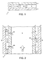
- Figure 1 shows a laminate, generally indicated at 1, having a gas-permeable layer 2, a gas-impervious layer 3 and one or more support strips 4a,4b,4c (spacing means).
- the gas-permeable layer 2 is made from a material comprising one or more aramids, such as, Nomex TM, and is capable of allowing gas to pass through the material.
- the material is gas-permeable because it is provided with a loose, porous weave, i.e. gas can easily pass through the weave, or the material is provided with holes or slots 7, to allow gas to pass through the holes or slots, in an otherwise gas-impervious material.
- the gas-impervious layer 3 is also made from a material comprising one or more aramids, such as Nomex TM. This material substantially prevents any gas from passing through it, as it is provided with a tight, non-porous weave.
- the one or more support strips 4a,4b,4c are designed to aid separation of the gas-permeable and gas-impervious layers 2,3, so as to provide spaces 5 therebetween, preferably, of predetermined height.
- the support strips 4a,4b,4c can be provided in sealing contact with both the gas-permeable and gas-impervious layers 2,3, as shown by reference 4a, or in sealing contact with only one layer, either the gas-permeable layer 2 or the gas-impervious layer 3, as shown by references 4b and 4c, respectively.
- the support strips are made from a material comprising an aramid, such as NomexTM or a polyester such as TraveraTM.
- the laminate 1, typically in the form of a sheet of laminate 1 can be formed into a duct 6 by sealing together a longitudinal edge of the laminate 1, most preferably, by sewing together the longitudinal edges.
- the duct is suitable for carrying a gas and, the gas-permeable layer 2 is provided as the innermost layer, and the gas-impervious layer 3, the outermost layer.
- a central space 8 is bounded by the gas-permeable layer 2 - through which space 8 a bulk portion of gas can pass - and a further space 5' is bounded by the gas-impervious layer 3 and the gas-permeable layer 2 - through which a smaller portion of gas can pass.
- Segments of duct 6 can be connected together.
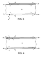
- Figure 3 shows and an end segment of duct 6 having an end 20, connectable to further ducts, and an end 21, connectable to air treatment and/or handling units.
- the ducts can be connected by a push-fit arrangement or any kind of fastening which provides a substantially gas-tight seal between the ducts, and/or air treatment and/or handling units.
- segments of duct 6 are connected by zips.
- Figure 4 shows a centre segment of duct 6 which is provided with two ends 20 connectable to further ducts 6.
- end segments of duct 6 are fixed to aluminium end pieces (not shown) which are in turn connected to the air treatment and/or handling units.
- the ducts 6 of the present invention are easily installed and can be easily disassembled for cleaning, unlike prior art aluminium ducts.
- the ducts 6 can be washed in a washing machine, or similar, so as to free entrapped particles and dust, etc. from the weave of the material
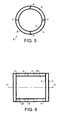
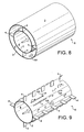
- Figure 5 shows an end-view of duct 6 of the present invention.
- the duct 6 is provided with four support strips 4, which aid separation of the gas-permeable and gas-impervious layers 2,3. Although four support strips 4 are shown, it is believed that, potentially, any number will do. However, two support strips are also preferred.
- FIG 6 a longitudinal cross-section of duct is shown represented by the two ends of the duct 6 cut off from a central portion of duct along the Line C. At each end 20 of the duct are positioned four support strips 4.
- Figure 9 shows an embodiment of an arrangement of support strips 4.
- spacing means can be arranged in any manner between the inner gas-permeable layer 2 and the outer gas-impervious layer 3, as long as the passage of gas AA through the space 5' is unhindered. It is further worth noting that the arrangement of spacing means 4 should not hinder the passage of gas AA through the inner gas-permeable layer 2.
- four support strips 4 are provided equally spaced around the circular cross-section of the duct 6.
- support strips 4 are located in lines along the length of the duct 6.
- the support strips 4 are also arranged so that the smallest cross-sectional area of strip faces the flow of gas AA through the space 5', so that the flow of gas AA is substantially unhindered.
- treated air indicated by Arrow A
- treated air from an air treatment and/or handling unit is passed through the duct 6 in the direction of the arrow.
- the bulk portion of air A passes through the central space 8 of the duct 6 and on to further ducts, etc.
- a smaller portion of the air A, shown by Arrows AA, passes through, or has already passed through, the gas-permeable layer 2 into the space 5' and also flows on to further ducts, etc. Whilst it is not desired to be bound by theory, it is believed that condensation is substantially or totally prevented from forming on the outside of the duct 6 because of this arrangement.
- the temperature of the air AA in the space 5' is subjected to a heating affect, which is caused by the temperature of air surrounding the duct, shown by Letter B, being of a higher temperature than the air AA, and the air B heating the outer surface of the gas-impervious layer 3, which causes localised heating of air AA in the space 5' which is around the surface of the gas-impervious layer 3, or in contact therewith. Therefore, a temperature buffer layer is formed in the space 5', such that the temperature of the air AA is between the temperature of the treated air A and that of the air B surrounding the duct 6. Accordingly, the dew-point of air B around the surface of the duct 6, or in contact therewith, is not reached and condensation does not form on the outer surface of the duct 6.
- any supports or spacing means can be used, provided that the flow of gas through the spaces 5,5' are substantially unhindered.
- meshes, tabs, semi-rigid foam or a fibrous filler material may be used between the gas-permeable and gas-impervious layers 2,3.
- the duct 6 can be of any shape, but circular, square or D-shaped cross-sections are most preferred, as these shapes correspond to prior art ducts.
- the aramid material which makes NomexTM and the polyester which makes TraveraTM are naturally fire-resistant. When alternative materials are used for the gas-permeable and/or gas-impervious layers, these materials may require the addition of a fire-retardant coating or additive.
- the ducts of the present invention may be folded for storage and/or transport to the site of assembly.
- the laminate and, therefore the duct may be provided with a second or subsequent gas-permeable layer, provided that the outermost layer of the duct is the gas-impervious layer.
- the duct is provided with two temperature buffer layers, so that a greater temperature differential between the treated air and air surrounding the duct can be accommodated.
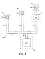
- Figure 7 shows an air circulation system 100 in which an air treatment unit 101, situated in compartment e, provides treated air to a number of other compartments a,b,c,d, spaced apart from compartment e.
- Each of compartments a,b,c are provided with one or more prior art textile ducts 102 (dispensation devices), for example, a duct such as one known under the trade mark Texvent.
- Compartment d is provided with an air handling unit 103.
- Ducts 6 of the present invention run from the air treatment unit 101 to compartments a,b,d and also from compartment d to compartment c.
- treated air from the air treatment unit 101 passes along ducts 6, of the present invention, to compartments a,b,c,d. During its passage, substantially no treated air is lost from the ducts 6 and substantially no condensation forms on the outside of the ducts 6. In compartments a,b,c the treated air passes into prior art textile ducts 102, from where the treated air can pass through the ducts 102 and provide treated air to the compartments.
- Textile ducts and ducting of the present invention are believed to be particularly useful in air treatment and/or distribution systems for the marine defence field.
- the claimed textile ducts may be used in both the commercial/building field and car/vehicle manufacture, as the technology of the ducts will be equally of use in those fields.
Landscapes
- Engineering & Computer Science (AREA)
- General Engineering & Computer Science (AREA)
- Mechanical Engineering (AREA)
- Textile Engineering (AREA)
- Chemical & Material Sciences (AREA)
- Combustion & Propulsion (AREA)
- Duct Arrangements (AREA)
- Laminated Bodies (AREA)
- Rigid Pipes And Flexible Pipes (AREA)
Claims (26)
- Conduit textile (6) apte à être utilisé dans un système de circulation d'air pour transporter un fluide tout en empêchant la formation d'une condensation sur celui-ci, le conduit (6) comprenant une couche intérieure perméable aux gaz (2) et une couche extérieure imperméable aux gaz (3) réalisée en un matériau comprenant un matériau textile, et des moyens d'écartement (4) situés entre les couches intérieure et extérieure (2 ; 3) pour réaliser un ou plusieurs espaces (5 ; 5') entre les couches perméable aux gaz et imperméable aux gaz (2 ; 3), lesdits espaces (5 ; 5') est/sont aptes à transporter un fluide en cours d'utilisation, caractérisé en ce que la couche intérieure (2) perméable aux gaz présente un tissage poreux qui permet le passage d'un fluide à travers la couche intérieure perméable aux gaz (2).
- Conduit selon la revendication 1, comprenant en outre une pluralité d'ouvertures (7) dans la couche intérieure perméable aux gaz (2) pour rendre la couche intérieure plus perméable.
- Conduit selon la revendication 1, dans lequel le(s) moyen d'écartement (4) est/sont sélectionnés parmi un ou plusieurs de bandes, pattes, mailles, maillages, matériaux fibreux et/ou mousses.
- Conduit selon la revendication 3, dans lequel le(s) moyens d'écartement (4) est/sont réalisés en contact étanche avec une ou plusieurs surfaces respectives de la couche intérieure et/ou de la couche extérieure (2 ; 3).
- Conduit selon l'une quelconque des revendications précédentes, dans lequel la couche intérieure et/ou la couche extérieure (2 ; 3) est/sont réalisées en un matériau tissé.
- Conduit selon l'une quelconque des revendications précédentes, dans lequel la couche extérieure (3) est réalisée en un matériau comprenant un aramide et/ou un polyester.
- Conduit selon la revendication 6, dans lequel le matériau possède un tissage sensiblement non poreux.
- Conduit selon la revendication 6 ou la revendication 7, dans lequel l'aramide est le Nomex™.
- Conduit selon l'une quelconque des revendications précédentes, dans lequel la couche intérieure (2) est réalisée en un matériau comprenant un aramide et/ou un polyester.
- Conduit selon la revendication 9, dans lequel le matériau possède un tissage poreux.
- Conduit selon la revendication 9 ou la revendication 10, dans lequel l'aramide est le Nomex™.
- Conduit selon l'une quelconque des revendications précédentes, et comprenant en outre un matériau ignifuge.
- Conduit selon la revendication 12, dans lequel le matériau ignifuge est associé au matériau formant la couche intérieure (2) et/ou la couche extérieure (3), et/ou un ou plusieurs moyens d'écartement précités (4) entre la couche intérieure et les couches extérieures.
- Conduit selon l'une quelconque des revendications précédentes, dans lequel le conduit (6) a une section transversale sensiblement circulaire, en forme de D ou en quadrant.
- Conduit selon l'une quelconque des revendications précédentes, et comprenant en outre des moyens de fixations, de préférence un ou plusieurs fermetures à glissière.
- Conduit selon l'une quelconque des revendications précédentes, comprenant en outre une ou plusieurs couches additionnelles perméables aux gaz interposées entre les couches intérieure et extérieure.
- Conduit selon l'une quelconque des revendications précédentes, dans lequel la couche intérieure perméable aux gaz et la couche extérieure imperméable aux gaz (2 ; 3) sont formées à partir d'un ou de plusieurs matériaux comprenant un matériau résistant aux flammes ou un matériau ignifuge.
- Conduit selon la revendication 17, dans lequel le(s) moyen(s) d'écartement (4) est/sont formés à partir d'un ou de plusieurs matériaux comprenant un matériau résistant aux flammes ou un matériau ignifuge.
- Système de circulation d'air (100) comprenant un ou plusieurs conduits textiles tels que définis dans l'une quelconque des revendications 1 à 18.
- Système de circulation d'air selon la revendication 19, comprenant une ou plusieurs unités de traitement d'air (101) et/ou unités de manipulation d'air (103), où lesdits un ou plusieurs conduits (6) réalisent des passages par lesquels l'air traité peut passer de la ou des unités de traitement et/ou de manipulation (101, 103) à un point de distribution.
- Système de circulation d'air selon la revendication 19 ou la revendication 20, comprenant en outre un ou plusieurs dispositifs de distribution d'air (102), où lesdits un ou plusieurs conduits (6) fournissent de l'air traité à un ou plusieurs dispositifs de distribution précités (102).
- Système de circulation d'air selon l'une quelconque des revendications 19 à 21, dans lequel, en cours d'utilisation, le système de circulation d'air (100) est configuré pour fournir l'air traité à une température inférieure à la température de l'air entourant un ou plusieurs conduits précités (6).
- Système de circulation d'air selon l'une quelconque des revendications 20 à 22, dans lequel, en cours d'utilisation, l'air est traité par les unités de traitement et/ou de manipulation d'air pour supprimer la poussière, les particules, l'humidité et/ou des agents nucléaires et/ou biologiques et/ou chimiques.
- Système de circulation d'air selon l'une quelconque des revendications 19 à 23, dans lequel le système de circulation d'air (100) est réalisé sur un vaisseau marin, comme un sous-marin ou un navire.
- Système de circulation d'air selon l'une quelconque des revendications 19 à 23, dans lequel le système de circulation d'air est réalisé dans un bâtiment.
- Système de circulation d'air selon l'une quelconque des revendications 19 à 23, dans lequel le système de circulation d'air est réalisé dans un véhicule, comme une voiture.
Applications Claiming Priority (3)
| Application Number | Priority Date | Filing Date | Title |
|---|---|---|---|
| US11/023,510 US7442121B2 (en) | 2004-12-29 | 2004-12-29 | Textile ducts |
| GB0428454A GB2421786B (en) | 2004-12-29 | 2004-12-29 | Improvements in or relating to textile ducts |
| PCT/GB2005/005042 WO2006070182A2 (fr) | 2004-12-29 | 2005-12-22 | Ameliorations pour conduits textiles |
Publications (2)
| Publication Number | Publication Date |
|---|---|
| EP1831596A2 EP1831596A2 (fr) | 2007-09-12 |
| EP1831596B1 true EP1831596B1 (fr) | 2013-04-24 |
Family
ID=35929587
Family Applications (1)
| Application Number | Title | Priority Date | Filing Date |
|---|---|---|---|
| EP05843719.5A Not-in-force EP1831596B1 (fr) | 2004-12-29 | 2005-12-22 | Ameliorations pour conduits textiles |
Country Status (6)
| Country | Link |
|---|---|
| EP (1) | EP1831596B1 (fr) |
| JP (1) | JP4787268B2 (fr) |
| AU (1) | AU2005321078B2 (fr) |
| DK (1) | DK1831596T3 (fr) |
| ES (1) | ES2406413T3 (fr) |
| WO (1) | WO2006070182A2 (fr) |
Families Citing this family (5)
| Publication number | Priority date | Publication date | Assignee | Title |
|---|---|---|---|---|
| KR100966726B1 (ko) * | 2010-01-05 | 2010-06-29 | 두현태 | 파일직물을 이용한 에어덕트 |
| ITTO20110896A1 (it) * | 2011-10-07 | 2013-04-08 | Bluethink S P A | Apparato tubolare per la realizzazione di strutture tubolari rigide e relativo procedimento di installazione |
| JP2013112158A (ja) * | 2011-11-29 | 2013-06-10 | Toyota Motor Corp | 車両の電池用冷却ダクト |
| CZ305561B6 (cs) * | 2014-10-20 | 2015-12-09 | Příhoda S.R.O. | Potrubí pro přepravu vzduchu |
| WO2016102634A1 (fr) * | 2014-12-24 | 2016-06-30 | Koninklijke Philips N.V. | Traitement de l'air |
Family Cites Families (18)
| Publication number | Priority date | Publication date | Assignee | Title |
|---|---|---|---|---|
| US2960924A (en) * | 1957-11-14 | 1960-11-22 | Frank S Grott | Air distributing conduit system for portable air conditioners |
| US3618509A (en) * | 1970-08-13 | 1971-11-09 | Mill Ind Inc | Collapsible ventilation system |
| JPS5022711U (fr) * | 1973-06-27 | 1975-03-14 | ||
| JPS5247133Y2 (fr) * | 1975-03-07 | 1977-10-26 | ||
| JPS5630793Y2 (fr) * | 1976-06-14 | 1981-07-22 | ||
| JPH0517542Y2 (fr) * | 1987-01-12 | 1993-05-11 | ||
| JPH0725540Y2 (ja) * | 1989-08-04 | 1995-06-07 | 旭ファイバーグラス株式会社 | 空調用ダクトの接続構造 |
| JPH0653895U (ja) * | 1991-12-25 | 1994-07-22 | アライ実業株式会社 | フレキシブルダクト |
| FR2713317B1 (fr) * | 1993-12-02 | 1996-02-23 | Grimaud Freres | Installation de diffusion d'air pour bâtiment d'élevage, notamment. |
| JPH07208799A (ja) * | 1994-01-12 | 1995-08-11 | Gunze Ltd | 空調用ダクト |
| JP3219649B2 (ja) * | 1995-08-07 | 2001-10-15 | タイガースポリマー株式会社 | 住宅用ダクトホース |
| JPH1054497A (ja) * | 1996-08-08 | 1998-02-24 | Tigers Polymer Corp | ダクトホース |
| JPH10160231A (ja) * | 1996-11-29 | 1998-06-19 | Kuraray Plast Kk | 送吸気用ダクト |
| FR2759153B1 (fr) * | 1997-01-31 | 1999-04-16 | Diffusion Thermique Ouest Sa | Systeme de diffusion d'air notamment pour le chauffage, le rafraichissement, l'humidification ou la ventilation d'un local |
| JPH10281353A (ja) * | 1997-04-07 | 1998-10-23 | Tigers Polymer Corp | ダクトホース |
| DE19853614C1 (de) * | 1998-11-20 | 2000-06-29 | Hummel Engineering Products Gm | Schlauchleitung mit endseitig festgelegtem Gewebestrumpf sowie deren Verwendung als Fangsicherung |
| CN1189128C (zh) * | 2000-02-25 | 2005-02-16 | 东拓工业株式会社 | 挠性软管 |
| US6565430B2 (en) * | 2001-09-13 | 2003-05-20 | Rite-Hite Holding Corporation | Pliable air duct with dust and condensation repellency |
-
2005
- 2005-12-22 WO PCT/GB2005/005042 patent/WO2006070182A2/fr active Application Filing
- 2005-12-22 EP EP05843719.5A patent/EP1831596B1/fr not_active Not-in-force
- 2005-12-22 AU AU2005321078A patent/AU2005321078B2/en not_active Ceased
- 2005-12-22 ES ES05843719T patent/ES2406413T3/es active Active
- 2005-12-22 DK DK05843719.5T patent/DK1831596T3/da active
- 2005-12-22 JP JP2007548889A patent/JP4787268B2/ja not_active Expired - Fee Related
Also Published As
| Publication number | Publication date |
|---|---|
| JP2008525760A (ja) | 2008-07-17 |
| EP1831596A2 (fr) | 2007-09-12 |
| AU2005321078B2 (en) | 2010-09-02 |
| AU2005321078A1 (en) | 2006-07-06 |
| WO2006070182A2 (fr) | 2006-07-06 |
| DK1831596T3 (da) | 2013-06-03 |
| ES2406413T3 (es) | 2013-06-06 |
| JP4787268B2 (ja) | 2011-10-05 |
| WO2006070182A3 (fr) | 2007-12-06 |
Similar Documents
| Publication | Publication Date | Title |
|---|---|---|
| US7442121B2 (en) | Textile ducts | |
| EP1831596B1 (fr) | Ameliorations pour conduits textiles | |
| CA2185405C (fr) | Methode de rainurage de panneaux isolants, d'isolant a tuyaux, et de materiau analogue produit a partir desdits panneaux | |
| EP0659130B1 (fr) | Isolation de vehicule amelioree et procede de fabrication et d'utilisation | |
| US6565430B2 (en) | Pliable air duct with dust and condensation repellency | |
| EP3088303B1 (fr) | Appareil de contrôle de bruit et de contrôle de flux dans un système de commande de l'environnement d'un avion | |
| US20130118830A1 (en) | Sound-absorptive panel for an air handling system | |
| EP0754141A1 (fr) | Couverture isolante semi-rigide et legere en mousse de polyimide prise en sandwich entre des couches de fibres de verre | |
| JP2009537346A (ja) | 複合板および複合板を排水する方法 | |
| GB2421786A (en) | Textile ducts for air circulation systems | |
| JP2008525760A5 (fr) | ||
| JP2006068727A (ja) | 除湿装置 | |
| US6797043B2 (en) | Encapsulated CO2 H2O sorbent | |
| US11191982B2 (en) | Fire-protection element and fire-protection wrap | |
| KR20070027763A (ko) | 절연 방법 | |
| PL116471B1 (en) | Container ship of refrigerating type | |
| US20200164715A1 (en) | Porous air inlet duct for a hvac system | |
| FI76878B (fi) | Foerfarande foer reglering av luftvaexling av byggnad och en konstruktion foer tillaempning av foerfarandet. | |
| CN115416835A (zh) | 一种汽车运输船及汽车运输船的通风方法 | |
| WO2004013545A1 (fr) | Panneau destine a un dispositif insonorisant aux fins d'attenuation du bruit engendre par la conduction d'un milieu aeriforme | |
| JP2024001747A (ja) | 粉塵フィルタ及び建物 |
Legal Events
| Date | Code | Title | Description |
|---|---|---|---|
| PUAI | Public reference made under article 153(3) epc to a published international application that has entered the european phase |
Free format text: ORIGINAL CODE: 0009012 |
|
| 17P | Request for examination filed |
Effective date: 20070718 |
|
| AK | Designated contracting states |
Kind code of ref document: A2 Designated state(s): AT BE BG CH CY CZ DE DK EE ES FI FR GB GR HU IE IS IT LI LT LU LV MC NL PL PT RO SE SI SK TR |
|
| AX | Request for extension of the european patent |
Extension state: AL BA HR MK YU |
|
| R17D | Deferred search report published (corrected) |
Effective date: 20071206 |
|
| DAX | Request for extension of the european patent (deleted) | ||
| RAP1 | Party data changed (applicant data changed or rights of an application transferred) |
Owner name: THOMSEN, NIELS ERIK Owner name: WELLMAN DEFENCE LIMITED |
|
| 17Q | First examination report despatched |
Effective date: 20081010 |
|
| REG | Reference to a national code |
Ref country code: DE Ref legal event code: R079 Ref document number: 602005039312 Country of ref document: DE Free format text: PREVIOUS MAIN CLASS: F16L0011200000 Ipc: F16L0011260000 |
|
| GRAP | Despatch of communication of intention to grant a patent |
Free format text: ORIGINAL CODE: EPIDOSNIGR1 |
|
| RIC1 | Information provided on ipc code assigned before grant |
Ipc: F16L 11/02 20060101ALI20121018BHEP Ipc: F24F 13/02 20060101ALI20121018BHEP Ipc: F24F 13/06 20060101ALI20121018BHEP Ipc: F16L 11/26 20060101AFI20121018BHEP Ipc: F16L 11/20 20060101ALI20121018BHEP Ipc: F16L 55/033 20060101ALI20121018BHEP |
|
| RAP1 | Party data changed (applicant data changed or rights of an application transferred) |
Owner name: THOMSEN, NIELS ERIK Owner name: ATMOSPHERE CONTROL INTERNATIONAL LIMITED |
|
| GRAS | Grant fee paid |
Free format text: ORIGINAL CODE: EPIDOSNIGR3 |
|
| GRAA | (expected) grant |
Free format text: ORIGINAL CODE: 0009210 |
|
| RBV | Designated contracting states (corrected) |
Designated state(s): AT BE BG CH CY CZ DE DK EE ES FI FR GR HU IE IS IT LI LT LU LV MC NL PL PT RO SE SI SK TR |
|
| AK | Designated contracting states |
Kind code of ref document: B1 Designated state(s): AT BE BG CH CY CZ DE DK EE ES FI FR GR HU IE IS IT LI LT LU LV MC NL PL PT RO SE SI SK TR |
|
| REG | Reference to a national code |
Ref country code: CH Ref legal event code: EP |
|
| REG | Reference to a national code |
Ref country code: AT Ref legal event code: REF Ref document number: 608824 Country of ref document: AT Kind code of ref document: T Effective date: 20130515 |
|
| REG | Reference to a national code |
Ref country code: IE Ref legal event code: FG4D |
|
| REG | Reference to a national code |
Ref country code: DK Ref legal event code: T3 |
|
| REG | Reference to a national code |
Ref country code: ES Ref legal event code: FG2A Ref document number: 2406413 Country of ref document: ES Kind code of ref document: T3 Effective date: 20130606 |
|
| REG | Reference to a national code |
Ref country code: SE Ref legal event code: TRGR |
|
| REG | Reference to a national code |
Ref country code: DE Ref legal event code: R096 Ref document number: 602005039312 Country of ref document: DE Effective date: 20130627 |
|
| REG | Reference to a national code |
Ref country code: NL Ref legal event code: T3 |
|
| RAP2 | Party data changed (patent owner data changed or rights of a patent transferred) |
Owner name: THOMSEN, NIELS ERIK Owner name: ATMOSPHERE CONTROL INTERNATIONAL LIMITED |
|
| REG | Reference to a national code |
Ref country code: AT Ref legal event code: MK05 Ref document number: 608824 Country of ref document: AT Kind code of ref document: T Effective date: 20130424 |
|
| REG | Reference to a national code |
Ref country code: LT Ref legal event code: MG4D |
|
| PG25 | Lapsed in a contracting state [announced via postgrant information from national office to epo] |
Ref country code: GR Free format text: LAPSE BECAUSE OF FAILURE TO SUBMIT A TRANSLATION OF THE DESCRIPTION OR TO PAY THE FEE WITHIN THE PRESCRIBED TIME-LIMIT Effective date: 20130725 Ref country code: AT Free format text: LAPSE BECAUSE OF FAILURE TO SUBMIT A TRANSLATION OF THE DESCRIPTION OR TO PAY THE FEE WITHIN THE PRESCRIBED TIME-LIMIT Effective date: 20130424 Ref country code: SI Free format text: LAPSE BECAUSE OF FAILURE TO SUBMIT A TRANSLATION OF THE DESCRIPTION OR TO PAY THE FEE WITHIN THE PRESCRIBED TIME-LIMIT Effective date: 20130424 Ref country code: IS Free format text: LAPSE BECAUSE OF FAILURE TO SUBMIT A TRANSLATION OF THE DESCRIPTION OR TO PAY THE FEE WITHIN THE PRESCRIBED TIME-LIMIT Effective date: 20130824 Ref country code: PT Free format text: LAPSE BECAUSE OF FAILURE TO SUBMIT A TRANSLATION OF THE DESCRIPTION OR TO PAY THE FEE WITHIN THE PRESCRIBED TIME-LIMIT Effective date: 20130826 Ref country code: FI Free format text: LAPSE BECAUSE OF FAILURE TO SUBMIT A TRANSLATION OF THE DESCRIPTION OR TO PAY THE FEE WITHIN THE PRESCRIBED TIME-LIMIT Effective date: 20130424 Ref country code: LT Free format text: LAPSE BECAUSE OF FAILURE TO SUBMIT A TRANSLATION OF THE DESCRIPTION OR TO PAY THE FEE WITHIN THE PRESCRIBED TIME-LIMIT Effective date: 20130424 Ref country code: BE Free format text: LAPSE BECAUSE OF FAILURE TO SUBMIT A TRANSLATION OF THE DESCRIPTION OR TO PAY THE FEE WITHIN THE PRESCRIBED TIME-LIMIT Effective date: 20130424 |
|
| PG25 | Lapsed in a contracting state [announced via postgrant information from national office to epo] |
Ref country code: LV Free format text: LAPSE BECAUSE OF FAILURE TO SUBMIT A TRANSLATION OF THE DESCRIPTION OR TO PAY THE FEE WITHIN THE PRESCRIBED TIME-LIMIT Effective date: 20130424 Ref country code: PL Free format text: LAPSE BECAUSE OF FAILURE TO SUBMIT A TRANSLATION OF THE DESCRIPTION OR TO PAY THE FEE WITHIN THE PRESCRIBED TIME-LIMIT Effective date: 20130424 Ref country code: CY Free format text: LAPSE BECAUSE OF FAILURE TO SUBMIT A TRANSLATION OF THE DESCRIPTION OR TO PAY THE FEE WITHIN THE PRESCRIBED TIME-LIMIT Effective date: 20130424 Ref country code: BG Free format text: LAPSE BECAUSE OF FAILURE TO SUBMIT A TRANSLATION OF THE DESCRIPTION OR TO PAY THE FEE WITHIN THE PRESCRIBED TIME-LIMIT Effective date: 20130724 |
|
| PG25 | Lapsed in a contracting state [announced via postgrant information from national office to epo] |
Ref country code: EE Free format text: LAPSE BECAUSE OF FAILURE TO SUBMIT A TRANSLATION OF THE DESCRIPTION OR TO PAY THE FEE WITHIN THE PRESCRIBED TIME-LIMIT Effective date: 20130424 Ref country code: SK Free format text: LAPSE BECAUSE OF FAILURE TO SUBMIT A TRANSLATION OF THE DESCRIPTION OR TO PAY THE FEE WITHIN THE PRESCRIBED TIME-LIMIT Effective date: 20130424 Ref country code: CZ Free format text: LAPSE BECAUSE OF FAILURE TO SUBMIT A TRANSLATION OF THE DESCRIPTION OR TO PAY THE FEE WITHIN THE PRESCRIBED TIME-LIMIT Effective date: 20130424 |
|
| PGFP | Annual fee paid to national office [announced via postgrant information from national office to epo] |
Ref country code: SE Payment date: 20131220 Year of fee payment: 9 Ref country code: DK Payment date: 20131223 Year of fee payment: 9 Ref country code: DE Payment date: 20131217 Year of fee payment: 9 |
|
| PG25 | Lapsed in a contracting state [announced via postgrant information from national office to epo] |
Ref country code: RO Free format text: LAPSE BECAUSE OF FAILURE TO SUBMIT A TRANSLATION OF THE DESCRIPTION OR TO PAY THE FEE WITHIN THE PRESCRIBED TIME-LIMIT Effective date: 20130424 |
|
| PGFP | Annual fee paid to national office [announced via postgrant information from national office to epo] |
Ref country code: NL Payment date: 20131213 Year of fee payment: 9 Ref country code: ES Payment date: 20131220 Year of fee payment: 9 Ref country code: IT Payment date: 20131220 Year of fee payment: 9 |
|
| PLBE | No opposition filed within time limit |
Free format text: ORIGINAL CODE: 0009261 |
|
| STAA | Information on the status of an ep patent application or granted ep patent |
Free format text: STATUS: NO OPPOSITION FILED WITHIN TIME LIMIT |
|
| 26N | No opposition filed |
Effective date: 20140127 |
|
| REG | Reference to a national code |
Ref country code: DE Ref legal event code: R097 Ref document number: 602005039312 Country of ref document: DE Effective date: 20140127 |
|
| PGFP | Annual fee paid to national office [announced via postgrant information from national office to epo] |
Ref country code: FR Payment date: 20131231 Year of fee payment: 9 |
|
| REG | Reference to a national code |
Ref country code: CH Ref legal event code: PL |
|
| PG25 | Lapsed in a contracting state [announced via postgrant information from national office to epo] |
Ref country code: LU Free format text: LAPSE BECAUSE OF FAILURE TO SUBMIT A TRANSLATION OF THE DESCRIPTION OR TO PAY THE FEE WITHIN THE PRESCRIBED TIME-LIMIT Effective date: 20131222 Ref country code: MC Free format text: LAPSE BECAUSE OF FAILURE TO SUBMIT A TRANSLATION OF THE DESCRIPTION OR TO PAY THE FEE WITHIN THE PRESCRIBED TIME-LIMIT Effective date: 20130424 |
|
| REG | Reference to a national code |
Ref country code: IE Ref legal event code: MM4A |
|
| PG25 | Lapsed in a contracting state [announced via postgrant information from national office to epo] |
Ref country code: CH Free format text: LAPSE BECAUSE OF NON-PAYMENT OF DUE FEES Effective date: 20131231 Ref country code: LI Free format text: LAPSE BECAUSE OF NON-PAYMENT OF DUE FEES Effective date: 20131231 Ref country code: IE Free format text: LAPSE BECAUSE OF NON-PAYMENT OF DUE FEES Effective date: 20131222 |
|
| REG | Reference to a national code |
Ref country code: DE Ref legal event code: R119 Ref document number: 602005039312 Country of ref document: DE |
|
| REG | Reference to a national code |
Ref country code: DK Ref legal event code: EBP Effective date: 20141231 |
|
| REG | Reference to a national code |
Ref country code: NL Ref legal event code: V1 Effective date: 20150701 |
|
| REG | Reference to a national code |
Ref country code: NL Ref legal event code: V1 Effective date: 20150701 |
|
| PG25 | Lapsed in a contracting state [announced via postgrant information from national office to epo] |
Ref country code: HU Free format text: LAPSE BECAUSE OF FAILURE TO SUBMIT A TRANSLATION OF THE DESCRIPTION OR TO PAY THE FEE WITHIN THE PRESCRIBED TIME-LIMIT; INVALID AB INITIO Effective date: 20051222 Ref country code: SE Free format text: LAPSE BECAUSE OF NON-PAYMENT OF DUE FEES Effective date: 20141223 |
|
| REG | Reference to a national code |
Ref country code: SE Ref legal event code: EUG |
|
| REG | Reference to a national code |
Ref country code: FR Ref legal event code: ST Effective date: 20150831 |
|
| PG25 | Lapsed in a contracting state [announced via postgrant information from national office to epo] |
Ref country code: NL Free format text: LAPSE BECAUSE OF NON-PAYMENT OF DUE FEES Effective date: 20150701 |
|
| PG25 | Lapsed in a contracting state [announced via postgrant information from national office to epo] |
Ref country code: DE Free format text: LAPSE BECAUSE OF NON-PAYMENT OF DUE FEES Effective date: 20150701 |
|
| PG25 | Lapsed in a contracting state [announced via postgrant information from national office to epo] |
Ref country code: FR Free format text: LAPSE BECAUSE OF NON-PAYMENT OF DUE FEES Effective date: 20141231 |
|
| PG25 | Lapsed in a contracting state [announced via postgrant information from national office to epo] |
Ref country code: IT Free format text: LAPSE BECAUSE OF NON-PAYMENT OF DUE FEES Effective date: 20141222 |
|
| REG | Reference to a national code |
Ref country code: ES Ref legal event code: FD2A Effective date: 20160127 |
|
| PG25 | Lapsed in a contracting state [announced via postgrant information from national office to epo] |
Ref country code: DK Free format text: LAPSE BECAUSE OF NON-PAYMENT OF DUE FEES Effective date: 20141231 |
|
| PG25 | Lapsed in a contracting state [announced via postgrant information from national office to epo] |
Ref country code: ES Free format text: LAPSE BECAUSE OF NON-PAYMENT OF DUE FEES Effective date: 20141223 |
|
| PG25 | Lapsed in a contracting state [announced via postgrant information from national office to epo] |
Ref country code: TR Free format text: LAPSE BECAUSE OF NON-PAYMENT OF DUE FEES Effective date: 20141222 |