EP1829768A2 - Cross member assembly for front ends - Google Patents
Cross member assembly for front ends Download PDFInfo
- Publication number
- EP1829768A2 EP1829768A2 EP07003819A EP07003819A EP1829768A2 EP 1829768 A2 EP1829768 A2 EP 1829768A2 EP 07003819 A EP07003819 A EP 07003819A EP 07003819 A EP07003819 A EP 07003819A EP 1829768 A2 EP1829768 A2 EP 1829768A2
- Authority
- EP
- European Patent Office
- Prior art keywords
- cross member
- mounting
- parts
- assembly according
- mounting bracket
- Prior art date
- Legal status (The legal status is an assumption and is not a legal conclusion. Google has not performed a legal analysis and makes no representation as to the accuracy of the status listed.)
- Granted
Links
Images


Classifications
-
- B—PERFORMING OPERATIONS; TRANSPORTING
- B62—LAND VEHICLES FOR TRAVELLING OTHERWISE THAN ON RAILS
- B62D—MOTOR VEHICLES; TRAILERS
- B62D25/00—Superstructure or monocoque structure sub-units; Parts or details thereof not otherwise provided for
- B62D25/08—Front or rear portions
- B62D25/082—Engine compartments
- B62D25/084—Radiator supports
Definitions
- the invention relates to a mounting group for front ends of based on a common platform vehicle bodies of passenger and light trucks, consisting of mounting brackets, each having an upper part with at least one upper cross member and laterally projecting headlamp supports and a lower part with at least two lateral vertical supports Connect the vertical supports of the lower part to the upper cross member of the upper part.
- the mounting bracket In preassemblable frontends, as is customary today for passenger and light trucks, the mounting bracket is of considerable importance, on the one hand its functionality with regard to the vehicle components to be arranged and on the other hand the design of the mounting bracket upper part, which in two respects is important.
- the vehicle headlamps are accommodated on the upper mounting carrier, which represent an essential design feature on the front of the vehicle with the inserted into the outer shell of the vehicle windows. If the headlamp design changes from vehicle model to vehicle model, the headlamp supports and mountings on the upper mounting bracket must be adjusted accordingly.
- the appearance of the upper cross member on the mounting bracket upper part which is usually the lock cross member, important because of the quality appearance.
- the invention is therefore an object of the invention to provide an assembly for assembling front ends of the type mentioned, in which the cost of adjusting the mounting bracket to the different design in the outer design variants of a vehicle model series, in which provided for the vehicle body, the same platform is reduced.
- a mounting bracket assembly characterized in that the upper parts and the lower parts of the mounting bracket separate, connectable with each other Components are, the tops are executed in mutually different variants, which are designed depending on the outer design of the respective vehicle body, wherein the lower parts are made to match the common platform of the vehicle bodies with each other the same.
- the entire range of vehicles of a model series can be covered with the same mounting base and the base parts combinable therewith, which have a different outer front design and their structure with the technical, not influenced by the design Components based on the same platform.
- the different, with the same lower part usable tops of the mounting bracket allow in a similar manner at the front ends differentiation between the design independent and the design-dependent components, it is therefore dealing with a platform-specific lower part and with vehicle-specific tops of the mounting bracket, both for the vehicle interior as well as for repairs cost advantages, because they are independently interchangeable.
- the respective upper part and the lower part of the respective mounting bracket are suitably releasably connected to each other by means of screws.
- the mounting bracket 1 of FIG. 1 is provided with an upper part 2.1, which has a mounting bracket 1 on the upper cross member 3.1, which acts in the installed position in the relevant vehicle as a lock cross member.
- This cross member 3.1 is continued in slightly angled towards the rear support arms 4.1, which are bolted in the installed position of the mounting bracket 1 with the lateral body structure of the vehicle.
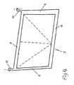
- the mounting bracket 1 further comprises a lower part 7, which are provided with lateral vertical beams 8. These vertical beams 8 engage in the cup-shaped projections 5 on the upper cross member 3.1, and in the region of these projections 5, the lower part 7 and the upper part 2.1 of the mounting bracket 1 are screwed together. As shown in FIG. 4, 7 mounting arms 13 are provided on the lower part, which engage behind the lugs 5 on the upper cross member 3.1 from below and cooperate with counter-devices 13 on the cross member 3.1 for screwing, which are indicated in Figs. 2 and 3.
- the lower part 7 is in the form of a rectangular frame and provided with an upper cross member 9, which connects the upper ends of the vertical beam 8 together. It also has a lower cross member 10, which extends between the lower ends of the vertical support 8.
- cooling components of the vehicle in question are added in the installed position, so ensures the rectangular shape of the lower part 7 for a sufficient cooling air passage with a large flow area.
- the frame-shaped lower part 7 of the mounting bracket 1 in the interior by means of diagonal extending vertical or vertical struts to be reinforced, which is indicated by dash-dotted lines.
- FIG. 2 shows the same mounting support upper frame 2.1 as FIG. 1.
- the upper part 2.1 is juxtaposed with another upper part 2.2, which can be seen from FIG. 3, which is shown with the same mounting support lower part 7 as in FIG a mounting bracket 1 can be joined, as it results from Fig. 5.
- the mounting bracket upper part 2.2 as one of the possible variants that can be combined with the mounting bracket lower part 7, differently designed headlight carrier 6.1, also the upper cross member 3.2 may be adapted to changing design requirements.
- the headlamp carriers 6.2 are connected to the lateral support arms 4.2 of the upper cross member 3.2 and form so-called receiving eyes for the vehicle headlights.
- the shell-shaped seats 5 of the mounting bracket upper part 2.2 are basically the same as those according to the embodiment of Figures 1 and 2, to screw it to the unchanged mounting bracket base 7 can.
- For further recording attachment options include here on the vertical lugs 5 further down reaching webs 11 at.
- the upper parts 2.1, 2.2 for the mounting bracket 1 which are adapted to the design variants of a vehicle model series, preferably consist of a metal-plastic composite, which offers both a plastic-covered metal profile and a hybrid solution.
- the platform-dependent lower part 7, which can be fitted with the design-dependent mounting support upper parts 2.1, 2.2, can be composed of individual metal profiles, produced as a plastic injection-molded part or as a metal hybrid part.
- the upper cross member 9 of the lower part 7 can take in accordance with rigid design, especially in steel functions of the upper cross member 3.1, 3.2 of the mounting brackets 2.1, 2.2, by attachment points for the hood lock of the vehicle in question are arranged on him.
Abstract
Description
Die Erfindung bezieht sich auf eine Montagegruppe für Frontends von auf einer gemeinsamen Plattform basierenden Fahrzeugaufbauten von Personen- und Kleinlastwagen, bestehend aus Montageträgern, welche jeweils ein Oberteil mit zumindest einem oberen Querträger sowie seitlich wegstehenden Scheinwerferträgern und ein Unterteil mit wenigstens zwei seitlichen Vertikalträgern aufweisen, wobei die Vertikalträger des Unterteils an den oberen Querträger des Oberteils anschließen.The invention relates to a mounting group for front ends of based on a common platform vehicle bodies of passenger and light trucks, consisting of mounting brackets, each having an upper part with at least one upper cross member and laterally projecting headlamp supports and a lower part with at least two lateral vertical supports Connect the vertical supports of the lower part to the upper cross member of the upper part.
Bei vormontierbaren Frontends, wie sie heute für Personen- und Kleinlastkraftwagen üblich sind, kommt dem Montageträger eine erhebliche Bedeutung zu, was zum einen seine Funktionalität im Hinblick auf die daran anzuordnenden Fahrzeugkomponenten und zum anderen das Design des Montageträger-Oberteils betrifft, welches in zweifacher Hinsicht von Bedeutung ist. Zum einen werden am Montageträger-Oberteil die Fahrzeug-Frontscheinwerfer aufgenom-men, die mit den in die Karosserieaußenhaut des Fahrzeugs einge-fügten Scheiben ein wesentliches Designmerkmal an der Frontseite des Fahrzeugs darstellen. Ändert sich von Fahrzeugmodell zu Fahrzeugmodell die Scheinwerfergestaltung, sind die Scheinwerferträger und -aufnahmen am Montageträger-Oberteil entsprechend anzupassen. Zum anderen ist für den sogenannten Blick unter die Motorhaube das Aussehen des oberen Querträgers am Montageträger-Oberteil, bei dem es sich in der Regel um den Schloßquerträger handelt, wegen der Qualitätsanmutung wichtig. Deshalb wird für die sichtbaren Bereiche des oberen Querträgers am Montageträger ein ansprechendes Design angestrebt, so kommt es auch hier darauf an, für das betreffende Fahrzeugmodell eine individuell optimale Lösung zu finden. In bekannter Ausführung umfassen deshalb die Montageträger für Fahrzeugfrontends sowohl die vom Design beeinflußten Bauteile wie auch die ausschließlich technischen Bedingungen entsprechenden Teile. So ist bei einer Modellreihe für jede Designvariante, soweit es den Fahrzeugfrontbereich betrifft, der Einsatz eines geänderten Montageträgers erforderlich.In preassemblable frontends, as is customary today for passenger and light trucks, the mounting bracket is of considerable importance, on the one hand its functionality with regard to the vehicle components to be arranged and on the other hand the design of the mounting bracket upper part, which in two respects is important. On the one hand, the vehicle headlamps are accommodated on the upper mounting carrier, which represent an essential design feature on the front of the vehicle with the inserted into the outer shell of the vehicle windows. If the headlamp design changes from vehicle model to vehicle model, the headlamp supports and mountings on the upper mounting bracket must be adjusted accordingly. On the other hand, for the so-called look under the hood, the appearance of the upper cross member on the mounting bracket upper part, which is usually the lock cross member, important because of the quality appearance. Therefore, for the visible Aspects of the upper cross member on mounting bracket an attractive design sought, so it is important here to find an individually optimal solution for the relevant vehicle model. In a known embodiment, therefore, include the mounting support for vehicle front ends both the design-influenced components as well as the only technical conditions corresponding parts. For example, with a model series for every design variant, as far as the front of the vehicle is concerned, the use of a modified mounting bracket is required.
Viele Kraftfahrzeughersteller verfolgen aus Kostengründen eine Plattformstrategie, um wichtige technische Komponenten für mehrere Fahrzeugmodelle gleich ausführen zu können, es handelt sich bei diesen Komponenten um sogenannte Wiederholteile. Nur die designrelevanten Bauteile, wie Scheinwerfer, Stoßfängerüber-züge oder Karosserieaußenhautteile, müssen individuell ausgebildet werden. Der Erfindung liegt deshalb die Aufgabe zugrunde, eine Baugruppe zum Zusammenstellen von Frontends der eingangs genannten Art zu schaffen, bei welcher der Aufwand für die Anpassung der Montageträger an die im äußeren Design voneinander verschiedenen Varianten einer Fahrzeugmodellreihe, bei welcher für den Fahrzeugaufbau die gleiche Plattform vorgesehen ist, verringert ist.For cost reasons, many motor vehicle manufacturers pursue a platform strategy in order to be able to execute important technical components for several vehicle models in the same way; these components are so-called repeating parts. Only the design-relevant components, such as headlights, bumper covers or body shell parts, must be individually designed. The invention is therefore an object of the invention to provide an assembly for assembling front ends of the type mentioned, in which the cost of adjusting the mounting bracket to the different design in the outer design variants of a vehicle model series, in which provided for the vehicle body, the same platform is reduced.
Diese Aufgabe wird mit einer Montageträger-Baugruppe dadurch gelöst, daß die Oberteile und die Unterteile der Montageträger separate, miteinander verbindbare Bauteile sind, wobei die Oberteile in voneinander verschiedenen Varianten ausgeführt sind, die in Abhängigkeit vom äußeren Design des jeweiligen Fahrzeugaufbaus gestaltet sind, wobei die Unterteile in Anpassung an die gemeinsame Plattform der Fahrzeugaufbauten untereinander gleich ausgeführt sind.This object is achieved with a mounting bracket assembly characterized in that the upper parts and the lower parts of the mounting bracket separate, connectable with each other Components are, the tops are executed in mutually different variants, which are designed depending on the outer design of the respective vehicle body, wherein the lower parts are made to match the common platform of the vehicle bodies with each other the same.
Für die Erfindung ist wesentlich, daß mit dem gleichen Montageträger-Unterteil und den damit kombinierbaren Montageträger-Oberteilen die gesamte Palette der Fahrzeuge einer Modellreihe abgedeckt werden kann, die ein unterschiedliches äußeres Front-Design aufweisen und deren Aufbau mit den technischen, nicht vom Design beeinflußten Bauteilen auf der gleichen Plattform basiert. Die unterschiedlichen, mit dem gleichen Unterteil verwendbaren Oberteile der Montageträger ermöglichen in analoger Weise bei den Frontends die Differenzierung zwischen den designunabhängigen und den designabhängigen Bauteilen, man hat es daher mit einem plattformspezifischen Unterteil und mit fahrzeugspezifischen Oberteilen der Montageträger zu tun, die sowohl für die Fahrzeugerstausstattung als auch für Reparaturen Kostenvorteile mit sich bringen, weil sie unabhängig voneinander austauschbar sind. So sind das jeweilige Oberteil und das Unterteil des betreffenden Montageträgers zweckmäßig mittels Verschraubungen lösbar miteinander verbunden.For the invention it is essential that the entire range of vehicles of a model series can be covered with the same mounting base and the base parts combinable therewith, which have a different outer front design and their structure with the technical, not influenced by the design Components based on the same platform. The different, with the same lower part usable tops of the mounting bracket allow in a similar manner at the front ends differentiation between the design independent and the design-dependent components, it is therefore dealing with a platform-specific lower part and with vehicle-specific tops of the mounting bracket, both for the vehicle interior as well as for repairs cost advantages, because they are independently interchangeable. Thus, the respective upper part and the lower part of the respective mounting bracket are suitably releasably connected to each other by means of screws.
Vorteilhafte Ausgestaltungsmerkmale der Erfindung ergeben sich aus den Unteransprüchen.Advantageous design features of the invention will become apparent from the dependent claims.
Die Erfindung wird nachfolgend anhand der Zeichnung an Ausführungsbeispielen noch näher erläutert. In der Zeichnung zeigen:
- Fig. 1
- einen Montageträger in schematischer, perspektivischer Darstellung in erster Ausführung,
- Fig. 2
- das Oberteil des Montageträgers nach Fig. 1,
- Fig. 3
- ein anstelle des Oberteils für den Montageträger nach den Figuren 1 und 2 verwendbares Oberteil,
- Fig. 4
- das Unterteil des Montageträgers nach Fig. 1 und
- Fig. 5
- einen Montageträger, der mit dem Montageträger-Oberteil gemäß Fig. 3 und dem Unterteil nach Fig. 3 versehen ist.
- Fig. 1
- a mounting bracket in a schematic, perspective view in the first embodiment,
- Fig. 2
- the upper part of the mounting carrier according to Fig. 1,
- Fig. 3
- a upper part which can be used instead of the upper part for the mounting carrier according to FIGS. 1 and 2,
- Fig. 4
- the lower part of the mounting bracket of FIG. 1 and
- Fig. 5
- a mounting bracket, which is provided with the mounting bracket upper part of FIG. 3 and the lower part of FIG.
Der Montageträger 1 nach Fig. 1 ist mit einem Oberteil 2.1 versehen, welches einen am Montageträger 1 oberen Querträger 3.1 aufweist, der in der Einbaulage bei dem betreffenden Fahrzeug als Schloßquerträger fungiert. Dieser Querträger 3.1 setzt sich in leicht nach hinten hin abgewinkelten Trägerarmen 4.1 fort, die in der Einbaulage des Montageträgers 1 mit der seitlichen Karosseriestruktur des Fahrzeugs verschraubt werden.The mounting bracket 1 of FIG. 1 is provided with an upper part 2.1, which has a mounting bracket 1 on the upper cross member 3.1, which acts in the installed position in the relevant vehicle as a lock cross member. This cross member 3.1 is continued in slightly angled towards the rear support arms 4.1, which are bolted in the installed position of the mounting bracket 1 with the lateral body structure of the vehicle.
Am Übergang zwischen dem oberen Querträger 3.1 und seinen seitlichen Trägerarmen 4.1 schließen nach unten hin schalenförmige Ansätze 5 an, von denen nach seitlich außen vorstehende Scheinwerferträger 6.1 abgewinkelt sind, die als Kragarme mit freien Enden ausgeführt sind.At the transition between the upper cross member 3.1 and its lateral support arms 4.1 close at the bottom cup-
Der Montageträger 1 weist weiter ein Unterteil 7 auf, welches mit seitlichen Vertikalträgern 8 versehen sind. Diese Vertikalträger 8 greifen in die schalenförmigen Ansätze 5 am oberen Querträger 3.1 ein, und im Bereich dieser Ansätze 5 sind das Unterteil 7 und das Oberteil 2.1 des Montageträgers 1 miteinander verschraubt. Wie hierzu Fig. 4 zeigt, sind am Unterteil 7 Befestigungsarme 13 vorgesehen, welche die Ansätze 5 am oberen Querträger 3.1 von unten her hintergreifen und mit Gegeneinrichtungen 13 am Querträger 3.1 zum Verschrauben zusammenwirken, die in Fig. 2 und 3 angedeutet sind.The mounting bracket 1 further comprises a
Das Unterteil 7 ist in Form eines rechteckigen Rahmens ausgeführt und dazu mit einem oberen Querholm 9 versehen, welcher die Oberenden der Vertikalträger 8 miteinander verbindet. Es weist ferner einen unteren Querholm 10 auf, welcher sich zwischen den Unterenden der Vertikalträger 8 erstreckt. In dem Unterteil 7 des Montageträgers 1 werden in der Einbaulage Kühlkomponenten des betreffenden Fahrzeugs aufgenommen, so sorgt die Rechteckform des Unterteils 7 für einen ausreichenden Kühlluftdurchlaß mit einer großen Durchströmungsfläche. Je nach den aufzunehmenden Kräften kann das rahmenförmige Unterteil 7 des Montageträgers 1 im Innern mittels diagonal verlaufender oder vertikaler Streben verstärkt sein, was durch strichpunktierte Linien angedeutet ist.The
Fig. 2 zeigt das gleiche Montageträger-Obergestell 2.1 wie Fig. 1. Das Oberteil 2.1 ist einem weiteren Oberteil 2.2, welches aus Fig. 3 ersichtlich ist, gegenübergestellt, welches mit dem gleichen Montageträger-Unterteil 7 wie in Fig. 4 dargestellt, zu einem Montageträger 1 zusammengefügt werden kann, wie er sich aus Fig. 5 ergibt.FIG. 2 shows the same mounting support upper frame 2.1 as FIG. 1. The upper part 2.1 is juxtaposed with another upper part 2.2, which can be seen from FIG. 3, which is shown with the same mounting support
So hat das Montageträger-Oberteil 2.2 als eine der möglichen Varianten, die mit dem Montageträger-Unterteil 7 kombiniert werden können, anders gestaltete Scheinwerferträger 6.1, auch kann der obere Querträger 3.2 geänderten Designerfordernissen angepaßt sein. Die Scheinwerferträger 6.2 sind an die seitlichen Trägerarme 4.2 des oberen Querträgers 3.2 angebunden und bilden sogenannte Aufnahmeaugen für die Fahrzeugfrontscheinwerfer. Die schalenförmigen Ansitze 5 des Montageträger-Oberteils 2.2 sind grundsätzlich die gleichen wie die nach dem Ausführungsbeispiel der Figuren 1 und 2, um daran das unveränderte Montageträger-Unterteil 7 verschrauben zu können. Für weitere Aufnahme-Befestigungsmöglichkeiten schließen hier an die vertikalen Ansätze 5 weiter nach unten reichende Stege 11 an.Thus, the mounting bracket upper part 2.2 as one of the possible variants that can be combined with the mounting bracket
Die Oberteile 2.1, 2.2 für die Montageträger 1, die den Designvarianten einer Fahrzeug-Modellreihe angepaßt sind, bestehen vorzugsweise aus einem Metall-Kunststoffverbund, wozu sich sowohl ein kunststoffabgedecktes Metallprofil wie auch eine Hybridlösung anbietet.The upper parts 2.1, 2.2 for the mounting bracket 1, which are adapted to the design variants of a vehicle model series, preferably consist of a metal-plastic composite, which offers both a plastic-covered metal profile and a hybrid solution.
Das mit den designabhängigen Montageträger-Oberteilen 2.1, 2.2 fügbare, plattformabhängige Unterteil 7 kann aus einzelnen Metallprofilen zusammengesetzt, als Kunststoffspritzgußteil oder als Metallhybridteil hergestellt sein. Der obere Querholm 9 des Unterteils 7 kann bei entsprechend steifer Ausführung insbesondere in Stahl Funktionen des oberen Querträgers 3.1, 3.2 der Montageträger-Oberteile 2.1, 2.2 übernehmen, indem an ihm Befestigungspunkte für das Haubenschloß des betreffenden Fahrzeugs angeordnet werden.The platform-dependent
Claims (8)
dadurch gekennzeichnet,
daß die Oberteile (2.1, 2.2) und die Unterteile (7) der Montageträger (1) separate, miteinander verbindbare Bauteile sind, wobei die Oberteile (2.1, 2.2) in voneinander verschiedenen Varianten ausgeführt sind, die in Abhängigkeit vom äußeren Design des jeweiligen Fahrzeugaufbaus gestaltet sind, wobei die Unterteile (7) in Anpassung an die gemeinsame Plattform der Fahrzeugaufbauten untereinander gleich ausgeführt sind.Assembly support assembly for front ends of based on a common platform vehicle bodies of passenger and light trucks, consisting of mounting brackets (1), each having an upper part (2.1, 2.2) with at least one upper cross member (3.1, 3.2) and laterally projecting headlamp supports (6.1 , 6.2) and a lower part (7) having at least two lateral vertical supports (8), wherein the vertical support (8) of the lower part (7) to the upper cross member (3.1, 3.2) of the upper part (2.1, 2.2),
characterized,
that the upper parts (2.1, 2.2) and the lower parts (7) of the mounting bracket (1) are separate, interconnectable components, wherein the upper parts (2.1, 2.2) are executed in mutually different variants, depending on the outer design of the respective vehicle body are designed, wherein the lower parts (7) are made equal to each other in adaptation to the common platform of the vehicle bodies.
dadurch gekennzeichnet,
daß die Oberteile (2.1, 2.2) und das Unterteil (7) für die Montageträger (1) aufeinander abgestimmte Einrichtungen zum Verschrauben miteinander haben.Assembly according to claim 1,
characterized,
that the upper parts (2.1, 2.2) and the lower part (7) for the mounting bracket (1) have matched devices for screwing together.
dadurch gekennzeichnet,
daß das Unterteil (7) für die Montageträger (1) einen oberen Querholm (9) aufweist, welcher die seitlichen Vertikalträger (8) an ihren Oberenden miteinander verbindet.Assembly according to claim 1 or 2,
characterized,
in that the lower part (7) for the mounting supports (1) has an upper transverse spar (9) which connects the lateral vertical supports (8) to each other at their upper ends.
dadurch gekennzeichnet,
daß das Unterteil (7) für die Montageträger (1) einen unteren Querholm (10) aufweist, welcher die Vertikalträger (8) an ihren Unterenden miteinander verbindet.Assembly according to one of claims 1 - 3,
characterized,
in that the lower part (7) for the mounting supports (1) has a lower transverse spar (10) which connects the vertical supports (8) to one another at their lower ends.
dadurch gekennzeichnet,
daß das Unterteil (7) für die Montageträger (1) mit seinen seitlichen Vertikalträgern (8), dem oberen Querholm (9) und dem unteren Querholm (10) als Rahmen mit einer rechteckigen Grundform ausgeführt ist.Assembly according to Claims 3 and 4,
characterized,
that the lower part (7) for the mounting support (1) with its lateral vertical beams (8), the upper cross member (9) and the lower cross member (10) is designed as a frame with a rectangular basic shape.
dadurch gekennzeichnet,
daß das Unterteil (7) für die Montageträger (1) mit seinen seitlichen Vertikalträgern (8), dem oberen Querholm (9) und dem unteren Querholm (10) in Stahl ausgeführt ist.Assembly according to one of claims 3 - 5,
characterized,
that the lower part (7) for the mounting support (1) with its lateral vertical beams (8), the upper cross member (9) and the lower cross member (10) is made of steel.
dadurch gekennzeichnet,
daß die Oberteile (2.1, 2.2) und/oder das Unterteil (7) für die Montageträger (1) Formteile aus einem Kunststoff oder einem Kunststoff-Metall-Verbund sind.Assembly according to one of claims 1 - 5,
characterized,
that the upper parts (2.1, 2.2) and / or the lower part (7) for the mounting support (1) molded parts made of a plastic or a plastic-metal composite are.
dadurch gekennzeichnet,
daß an dem oberen Querträger (3.1, 3.2) der Oberteile (2.1, 2.2) für die Montageträger (1) nach unten vorstehende, schalenförmige Ansätze (5) angeformt sind, die bei dem jeweiligen, zusammengefügten Montageträger die Vertikalträger (8) des Unterteils (7) übergreifen.Assembly according to claim 7,
characterized,
that on the upper cross member (3.1, 3.2) of the upper parts (2.1, 2.2) for the mounting bracket (1) downwardly projecting, cup-shaped projections (5) are formed, which in the respective assembled assembly support the vertical support (8) of the lower part ( 7) overlap.
Applications Claiming Priority (1)
| Application Number | Priority Date | Filing Date | Title |
|---|---|---|---|
| DE200610009902 DE102006009902A1 (en) | 2006-03-03 | 2006-03-03 | Assembly for assembling frontends |
Publications (3)
| Publication Number | Publication Date |
|---|---|
| EP1829768A2 true EP1829768A2 (en) | 2007-09-05 |
| EP1829768A3 EP1829768A3 (en) | 2008-04-16 |
| EP1829768B1 EP1829768B1 (en) | 2009-08-12 |
Family
ID=38176799
Family Applications (1)
| Application Number | Title | Priority Date | Filing Date |
|---|---|---|---|
| EP20070003819 Expired - Fee Related EP1829768B1 (en) | 2006-03-03 | 2007-02-24 | Cross member assembly for front ends |
Country Status (2)
| Country | Link |
|---|---|
| EP (1) | EP1829768B1 (en) |
| DE (2) | DE102006009902A1 (en) |
Cited By (1)
| Publication number | Priority date | Publication date | Assignee | Title |
|---|---|---|---|---|
| US10358027B2 (en) | 2014-12-22 | 2019-07-23 | Volkswagen Aktiengesellschaft | Series of mounting supports and mounting support for fastening radiator modules, and method for manufacturing mounting supports |
Families Citing this family (4)
| Publication number | Priority date | Publication date | Assignee | Title |
|---|---|---|---|---|
| DE102010005835B4 (en) * | 2010-01-27 | 2023-12-07 | Bayerische Motoren Werke Aktiengesellschaft | Cross member arrangement of a body of a passenger car |
| DE102012008035B4 (en) | 2012-04-21 | 2016-12-01 | Hbpo Gmbh | Mounting support and motor vehicle front end |
| DE102012023674A1 (en) | 2012-11-28 | 2014-05-28 | GM Global Technology Operations LLC (n. d. Ges. d. Staates Delaware) | Motor vehicle with modular bodywork |
| DE102013017700A1 (en) * | 2013-10-24 | 2015-04-30 | Daimler Ag | Front end cross member for a motor vehicle |
Citations (5)
| Publication number | Priority date | Publication date | Assignee | Title |
|---|---|---|---|---|
| EP1072501A2 (en) * | 1999-07-30 | 2001-01-31 | Valeo Inc. | Modular front end of a vehicle |
| EP1072476A2 (en) * | 1999-07-26 | 2001-01-31 | Dynamit Nobel Kunststoff GmbH | Bumper support for improved pedestrian protection on motor vehicles |
| FR2805497A1 (en) * | 2000-02-28 | 2001-08-31 | Valeo Thermique Moteur Sa | Vehicle radiator mounting is assembled in two parts, with radiator fitting between and with connectors to radiator end containers, integrated into front face assembly |
| WO2002036414A1 (en) * | 2000-11-06 | 2002-05-10 | Valeo Thermique Moteur | Motor vehicle front surface comprising a bumper beam |
| WO2003053768A1 (en) * | 2001-12-20 | 2003-07-03 | Valeo Thermique Moteur | Motor vehicle front end comprising a fluid tank |
Family Cites Families (2)
| Publication number | Priority date | Publication date | Assignee | Title |
|---|---|---|---|---|
| DE19603957C2 (en) * | 1996-02-05 | 2000-06-29 | Wagon Automotive Gmbh | Upper cross member of a vehicle front end part |
| DE19919258C2 (en) * | 1999-04-28 | 2002-01-17 | Porsche Ag | Front end module for a vehicle body |
-
2006
- 2006-03-03 DE DE200610009902 patent/DE102006009902A1/en not_active Withdrawn
-
2007
- 2007-02-24 DE DE200750001266 patent/DE502007001266D1/en active Active
- 2007-02-24 EP EP20070003819 patent/EP1829768B1/en not_active Expired - Fee Related
Patent Citations (5)
| Publication number | Priority date | Publication date | Assignee | Title |
|---|---|---|---|---|
| EP1072476A2 (en) * | 1999-07-26 | 2001-01-31 | Dynamit Nobel Kunststoff GmbH | Bumper support for improved pedestrian protection on motor vehicles |
| EP1072501A2 (en) * | 1999-07-30 | 2001-01-31 | Valeo Inc. | Modular front end of a vehicle |
| FR2805497A1 (en) * | 2000-02-28 | 2001-08-31 | Valeo Thermique Moteur Sa | Vehicle radiator mounting is assembled in two parts, with radiator fitting between and with connectors to radiator end containers, integrated into front face assembly |
| WO2002036414A1 (en) * | 2000-11-06 | 2002-05-10 | Valeo Thermique Moteur | Motor vehicle front surface comprising a bumper beam |
| WO2003053768A1 (en) * | 2001-12-20 | 2003-07-03 | Valeo Thermique Moteur | Motor vehicle front end comprising a fluid tank |
Cited By (1)
| Publication number | Priority date | Publication date | Assignee | Title |
|---|---|---|---|---|
| US10358027B2 (en) | 2014-12-22 | 2019-07-23 | Volkswagen Aktiengesellschaft | Series of mounting supports and mounting support for fastening radiator modules, and method for manufacturing mounting supports |
Also Published As
| Publication number | Publication date |
|---|---|
| EP1829768B1 (en) | 2009-08-12 |
| DE502007001266D1 (en) | 2009-09-24 |
| DE102006009902A1 (en) | 2007-09-06 |
| EP1829768A3 (en) | 2008-04-16 |
Similar Documents
| Publication | Publication Date | Title |
|---|---|---|
| DE102009009882B4 (en) | Front module for a motor vehicle | |
| DE60115518T2 (en) | End module for a motor vehicle | |
| DE69910537T2 (en) | FRONT FRONT MADE OF REINFORCED METAL AND PLASTIC COMPOSITE MATERIAL FOR MOTOR VEHICLES | |
| DE3813455C2 (en) | ||
| EP2024222B1 (en) | Fender module | |
| DE69908529T2 (en) | Method for manufacturing a structure for the front of motor vehicles, and structure for the front of motor vehicles produced by this method | |
| EP1048554A2 (en) | Front module for the bodywork of a motor vehicle | |
| DE102006041664A1 (en) | Carrier arrangement for attachment of rear axle arrangement of lorry to vehicle frame, has cross member carrier part extending in distance to axial arrangement approximately to height of frame longitudinal carriers of vehicle frame | |
| DE10151684A1 (en) | Sidewall assembly for a motor vehicle body | |
| EP1829768B1 (en) | Cross member assembly for front ends | |
| EP1920998B1 (en) | Motor vehicle bodywork and assembly method therefor | |
| EP1588920A1 (en) | Energy absorbing steering wheel | |
| EP1627800B1 (en) | Vehicle front part | |
| DE102012109498A1 (en) | Device for mounting a fender of a vehicle | |
| DE102004007571A1 (en) | Front section for a vehicle, in particular, a motor vehicle comprises at least one pedestrian protection beam which is produced as a single-piece plastic component | |
| DE102010005834A1 (en) | Support arrangement for windscreen of body of passenger vehicle, has cross beam and support element, which comprises support section for indirect support of windscreen | |
| DE102011119168B4 (en) | Front spoiler | |
| DE102010022738A1 (en) | Front end for motor car, has assembly carrier secured at vehicle longitudinal beam, and bending test girder connected with longitudinal beam by crash box and with assembly carrier by deformable holder | |
| DE102005017249A1 (en) | Body section for vehicle has rear end floor bearing upon both rear longitudinal beams and rear axle cross member as integratable rear end structure module | |
| EP1083118B1 (en) | Structural assembly support for the front part of a vehicle | |
| DE102015011044A1 (en) | Rear structure for a passenger car | |
| DE102004038893A1 (en) | Front end module for a vehicle, in particular, a motor vehicle comprises a section which serves as a carrier of installed items, and is joined to a pedestrian protection beam and/or to a bumper cross beam | |
| DE102014019333A1 (en) | Support for a motor vehicle, method for producing such a support and modular system for a plurality of construction variants of such a support | |
| EP1953042B1 (en) | Roof rack for vehicles | |
| DE102021116097B3 (en) | Modular system for a structural element of a passenger car body |
Legal Events
| Date | Code | Title | Description |
|---|---|---|---|
| PUAI | Public reference made under article 153(3) epc to a published international application that has entered the european phase |
Free format text: ORIGINAL CODE: 0009012 |
|
| AK | Designated contracting states |
Kind code of ref document: A2 Designated state(s): AT BE BG CH CY CZ DE DK EE ES FI FR GB GR HU IE IS IT LI LT LU LV MC NL PL PT RO SE SI SK TR |
|
| AX | Request for extension of the european patent |
Extension state: AL BA HR MK YU |
|
| PUAL | Search report despatched |
Free format text: ORIGINAL CODE: 0009013 |
|
| AK | Designated contracting states |
Kind code of ref document: A3 Designated state(s): AT BE BG CH CY CZ DE DK EE ES FI FR GB GR HU IE IS IT LI LT LU LV MC NL PL PT RO SE SI SK TR |
|
| AX | Request for extension of the european patent |
Extension state: AL BA HR MK RS |
|
| 17P | Request for examination filed |
Effective date: 20080729 |
|
| AKX | Designation fees paid |
Designated state(s): DE FR GB IT |
|
| GRAP | Despatch of communication of intention to grant a patent |
Free format text: ORIGINAL CODE: EPIDOSNIGR1 |
|
| GRAS | Grant fee paid |
Free format text: ORIGINAL CODE: EPIDOSNIGR3 |
|
| GRAA | (expected) grant |
Free format text: ORIGINAL CODE: 0009210 |
|
| AK | Designated contracting states |
Kind code of ref document: B1 Designated state(s): DE FR GB IT |
|
| REG | Reference to a national code |
Ref country code: GB Ref legal event code: FG4D Free format text: NOT ENGLISH |
|
| REF | Corresponds to: |
Ref document number: 502007001266 Country of ref document: DE Date of ref document: 20090924 Kind code of ref document: P |
|
| PLBE | No opposition filed within time limit |
Free format text: ORIGINAL CODE: 0009261 |
|
| STAA | Information on the status of an ep patent application or granted ep patent |
Free format text: STATUS: NO OPPOSITION FILED WITHIN TIME LIMIT |
|
| 26N | No opposition filed |
Effective date: 20100517 |
|
| PGRI | Patent reinstated in contracting state [announced from national office to epo] |
Ref country code: IT Effective date: 20110501 |
|
| REG | Reference to a national code |
Ref country code: FR Ref legal event code: PLFP Year of fee payment: 10 |
|
| REG | Reference to a national code |
Ref country code: FR Ref legal event code: PLFP Year of fee payment: 11 |
|
| REG | Reference to a national code |
Ref country code: FR Ref legal event code: PLFP Year of fee payment: 12 |
|
| PGFP | Annual fee paid to national office [announced via postgrant information from national office to epo] |
Ref country code: GB Payment date: 20180126 Year of fee payment: 12 |
|
| PGFP | Annual fee paid to national office [announced via postgrant information from national office to epo] |
Ref country code: IT Payment date: 20180221 Year of fee payment: 12 |
|
| PGFP | Annual fee paid to national office [announced via postgrant information from national office to epo] |
Ref country code: DE Payment date: 20190208 Year of fee payment: 13 |
|
| PGFP | Annual fee paid to national office [announced via postgrant information from national office to epo] |
Ref country code: DE Payment date: 20190208 Year of fee payment: 13 Ref country code: FR Payment date: 20190221 Year of fee payment: 13 |
|
| GBPC | Gb: european patent ceased through non-payment of renewal fee |
Effective date: 20190224 |
|
| PG25 | Lapsed in a contracting state [announced via postgrant information from national office to epo] |
Ref country code: GB Free format text: LAPSE BECAUSE OF NON-PAYMENT OF DUE FEES Effective date: 20190224 |
|
| PG25 | Lapsed in a contracting state [announced via postgrant information from national office to epo] |
Ref country code: IT Free format text: LAPSE BECAUSE OF NON-PAYMENT OF DUE FEES Effective date: 20190224 |
|
| REG | Reference to a national code |
Ref country code: DE Ref legal event code: R119 Ref document number: 502007001266 Country of ref document: DE |
|
| PG25 | Lapsed in a contracting state [announced via postgrant information from national office to epo] |
Ref country code: DE Free format text: LAPSE BECAUSE OF NON-PAYMENT OF DUE FEES Effective date: 20200901 Ref country code: FR Free format text: LAPSE BECAUSE OF NON-PAYMENT OF DUE FEES Effective date: 20200229 |