EP1588920A1 - Energy absorbing steering wheel - Google Patents
Energy absorbing steering wheel Download PDFInfo
- Publication number
- EP1588920A1 EP1588920A1 EP05090115A EP05090115A EP1588920A1 EP 1588920 A1 EP1588920 A1 EP 1588920A1 EP 05090115 A EP05090115 A EP 05090115A EP 05090115 A EP05090115 A EP 05090115A EP 1588920 A1 EP1588920 A1 EP 1588920A1
- Authority
- EP
- European Patent Office
- Prior art keywords
- steering wheel
- cavity
- hub
- spokes
- sheath
- Prior art date
- Legal status (The legal status is an assumption and is not a legal conclusion. Google has not performed a legal analysis and makes no representation as to the accuracy of the status listed.)
- Granted
Links
- 238000010521 absorption reaction Methods 0.000 claims abstract description 10
- 239000006260 foam Substances 0.000 claims description 2
- 239000004033 plastic Substances 0.000 description 4
- 229920003023 plastic Polymers 0.000 description 4
- DOSMHBDKKKMIEF-UHFFFAOYSA-N 2-[3-(diethylamino)-6-diethylazaniumylidenexanthen-9-yl]-5-[3-[3-[4-(1-methylindol-3-yl)-2,5-dioxopyrrol-3-yl]indol-1-yl]propylsulfamoyl]benzenesulfonate Chemical compound C1=CC(=[N+](CC)CC)C=C2OC3=CC(N(CC)CC)=CC=C3C(C=3C(=CC(=CC=3)S(=O)(=O)NCCCN3C4=CC=CC=C4C(C=4C(NC(=O)C=4C=4C5=CC=CC=C5N(C)C=4)=O)=C3)S([O-])(=O)=O)=C21 DOSMHBDKKKMIEF-UHFFFAOYSA-N 0.000 description 1
- 239000004677 Nylon Substances 0.000 description 1
- 230000002745 absorbent Effects 0.000 description 1
- 239000002250 absorbent Substances 0.000 description 1
- 238000005253 cladding Methods 0.000 description 1
- 239000000945 filler Substances 0.000 description 1
- 238000004519 manufacturing process Methods 0.000 description 1
- 239000000463 material Substances 0.000 description 1
- 229920001778 nylon Polymers 0.000 description 1
Images

Classifications
-
- B—PERFORMING OPERATIONS; TRANSPORTING
- B60—VEHICLES IN GENERAL
- B60R—VEHICLES, VEHICLE FITTINGS, OR VEHICLE PARTS, NOT OTHERWISE PROVIDED FOR
- B60R21/00—Arrangements or fittings on vehicles for protecting or preventing injuries to occupants or pedestrians in case of accidents or other traffic risks
- B60R21/02—Occupant safety arrangements or fittings, e.g. crash pads
- B60R21/04—Padded linings for the vehicle interior ; Energy absorbing structures associated with padded or non-padded linings
- B60R21/05—Padded linings for the vehicle interior ; Energy absorbing structures associated with padded or non-padded linings associated with the steering wheel, steering hand lever or steering column
-
- B—PERFORMING OPERATIONS; TRANSPORTING
- B62—LAND VEHICLES FOR TRAVELLING OTHERWISE THAN ON RAILS
- B62D—MOTOR VEHICLES; TRAILERS
- B62D1/00—Steering controls, i.e. means for initiating a change of direction of the vehicle
- B62D1/02—Steering controls, i.e. means for initiating a change of direction of the vehicle vehicle-mounted
- B62D1/04—Hand wheels
- B62D1/11—Hand wheels incorporating energy-absorbing arrangements, e.g. by being yieldable or collapsible
-
- Y—GENERAL TAGGING OF NEW TECHNOLOGICAL DEVELOPMENTS; GENERAL TAGGING OF CROSS-SECTIONAL TECHNOLOGIES SPANNING OVER SEVERAL SECTIONS OF THE IPC; TECHNICAL SUBJECTS COVERED BY FORMER USPC CROSS-REFERENCE ART COLLECTIONS [XRACs] AND DIGESTS
- Y10—TECHNICAL SUBJECTS COVERED BY FORMER USPC
- Y10T—TECHNICAL SUBJECTS COVERED BY FORMER US CLASSIFICATION
- Y10T74/00—Machine element or mechanism
- Y10T74/20—Control lever and linkage systems
- Y10T74/20576—Elements
- Y10T74/20732—Handles
- Y10T74/20834—Hand wheels
Definitions
- the invention relates to an energy absorbing steering wheel according to the preamble of Claim 1.
- the invention is therefore based on the object, an energy absorbing steering wheel the latter type so that it with less effort and thus with lower costs can be produced.
- an energy absorbing steering wheel especially large-volume steering wheel for Truck, with a steering wheel skeleton with hub, spokes and steering wheel rim, which with a Sheath are provided, with the skeletal sections of the spokes from Steering wheel rim extending to the hub and where the area above the hub is designed to absorb energy.
- the Sheath at least in the region above the hub at least one cavity for Has support of energy absorption.
- this steering wheel according to the invention is deliberately used on plastic inserts made of a different type of plastic Energy absorption omitted. An energy absorption is through the cavity in Achieved connection with the steering wheel casing.
- a cavity extends from the Hub to the upper, the occupant facing area of the sheath.
- the sheath above the cavity has a thickness having a deformation on impact of the occupant without allowing break.
- a sheath made of PUR foam, in one embodiment above of the cavity has a thickness of. 10. bis.20.mm on.
- the cavity laterally into the area of Spokes extends.
- the cavity may have an opening which is closed by the plaque is.
- the energy absorption can in the inventive arrangement by more Changes can be easily adapted to different requirements. By changing the wall thickness, the energy absorption can be changed.
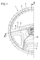
- Fig. 1 shows a steering wheel in plan view, wherein the steering wheel only halfway is shown.
- the right half not shown corresponds to the mirror image of shown left half.
- the steering wheel has a steering wheel rim 1, which consists of a dashed steering wheel rim skeleton 2 and a steering wheel rim casing third consists.
- the steering wheel has four spokes, of which only two spokes 4, 5 are shown.
- the spokes consist of a spoke skeleton 6 or 7 and a Speichenummantelung 8 and 9 respectively.
- the center of Cavity has an opening 13, which later by means of a badge, not shown is closed.
- the upper cover 12 Upon impact of an occupant on this steering wheel, the upper cover 12 deforms in the middle area of the steering wheel. As a result, the air in the cavity 11 is compressed and thus contributes to energy absorption.
Abstract
Description
Die Erfindung betrifft ein Energie absorbierendes Lenkrad nach dem Oberbegriff des
Anspruchs 1.The invention relates to an energy absorbing steering wheel according to the preamble of
Großvolumige Lenkräder, wie sie z. B. für Lastkraftwagen benutzt werden, weisen in der Regel keine Airbagmodule auf. So ist aus der DE 30 48 771 C2 ein Energie absorbierendes Lenkrad bekannt, bei dem der Lenkradkranz, die Speichen und ein sich zwischen den Speichen und der Lenkradnabe erstreckender dünnwandiger Pralltopf einstückig aus Nylon hergestellt sind. Dabei erstrecken sich die Speichen vom Lenkradkranz aus zum oberen Rand des Pralltopfes, der mittig am Lenkrad angeordnet ist und oben mit einer Prallplatte abgedeckt ist. Beim Aufprall des Fahrers auf das Lenkrad verformt sich zunächst die Prallplatte und anschließend der Pralltopf.Large-volume steering wheels, as z. B. are used for trucks, have in the Usually no airbag modules. Thus, from DE 30 48 771 C2 an energy absorbing steering wheel, in which the steering wheel rim, the spokes and a extending between the spokes and the steering wheel hub thin-walled baffle pot are made in one piece from nylon. The spokes extend from the Steering wheel rim out to the upper edge of the baffle, which is centered on the steering wheel is and is covered at the top with a baffle plate. Upon impact of the driver on the Steering wheel deforms first the baffle plate and then the baffle pot.
Aus der Praxis sind weiterhin Lenkräder bekannt, bei denen sich die Speichen und damit auch die Speichenverkleidung vom Lenkradkranz zur Lenkradnabe hin erstrecken. Bei diesen Lenkrädern sind als Füllstück und zur Energieabsorption Einlagen aus Energie absorbierenden Kunststoffen angeordnet. Dabei bestehen diese Einlagen aus einem anderen Material als die Lenkradumhüllung. Die Herstellung eines Lenkrades unter Verwendung unterschiedlicher Kunststoffe ist aufwendig und entsprechend teuer. From practice steering wheels are still known in which the spokes and thus also extend the spoke trim from the steering wheel rim to the steering wheel hub. at these steering wheels are as filler and for energy absorption deposits of energy arranged absorbent plastics. These deposits consist of a other material than the steering wheel cladding. The production of a steering wheel under Use of different plastics is expensive and correspondingly expensive.
Der Erfindung liegt deshalb die Aufgabe zugrunde, ein Energie absorbierendes Lenkrad der letztgenannten Art so aufzubauen, dass es mit geringerem Aufwand und damit mit geringeren Kosten herstellbar ist.The invention is therefore based on the object, an energy absorbing steering wheel the latter type so that it with less effort and thus with lower costs can be produced.
Erfindungsgemäß wird dass gemäß den Merkmalen des Anspruchs 1 erreicht.According to the invention that is achieved according to the features of
Bei einem Energie absorbierenden Lenkrad, insbesondere großvolumigen Lenkrad für LKW, mit einem Lenkradskelett mit Nabe, Speichen und Lenkradkranz, die mit einer Ummantelung versehen sind, wobei sich die Skelettabschnitte der Speichen vom Lenkradkranz bis zur Nabe erstrecken und wobei der Bereich oberhalb der Nabe energieabsorbierend ausgebildet ist,. ist erfindungsgemäß vorgesehen, dass die Ummantelung zumindest im Bereich oberhalb der Nabe mindestens einen Hohlraum zur Unterstützung der Energieabsorption aufweist. Bei diesem erfindungsgemäßen Lenkrad wird bewusst auf Kunststoffeinlagen aus einer anderen Kunststoffart zur Energieabsorption verzichtet. Eine Energieabsorption wird durch den Hohlraum in Verbindung mit der Lenkradummantelung erzielt.In an energy absorbing steering wheel, especially large-volume steering wheel for Truck, with a steering wheel skeleton with hub, spokes and steering wheel rim, which with a Sheath are provided, with the skeletal sections of the spokes from Steering wheel rim extending to the hub and where the area above the hub is designed to absorb energy. is inventively provided that the Sheath at least in the region above the hub at least one cavity for Has support of energy absorption. In this steering wheel according to the invention is deliberately used on plastic inserts made of a different type of plastic Energy absorption omitted. An energy absorption is through the cavity in Achieved connection with the steering wheel casing.
Durch die unterschiedliche Gestaltung des Hohlraumes kann die Größe der Energieabsorption beeinflusst werden. Vorzugsweise erstreckt sich ein Hohlraum von der Nabe bis in den oberen, dem Insassen zugekehrten Bereich der Ummantelung.Due to the different design of the cavity, the size of the Energy absorption can be influenced. Preferably, a cavity extends from the Hub to the upper, the occupant facing area of the sheath.
Es ist zweckmäßig, dass die Ummantelung oberhalb des Hohlraumes eine Dicke aufweist, die eine Verformung beim Aufprall des Insassen zulässt ohne dabei zu brechen. Eine Ummantelung aus PUR-Schaum weist in einer Ausführungsform oberhalb des Hohlraumes eine Dicke von. 10. bis.20.mm auf.It is appropriate that the sheath above the cavity has a thickness having a deformation on impact of the occupant without allowing break. A sheath made of PUR foam, in one embodiment above of the cavity has a thickness of. 10. bis.20.mm on.
Es ist weiterhin zweckmäßig, dass sich der Hohlraum seitlich bis in den Bereich der Speichen erstreckt. Im Bereich einer auf der Lenkradummantelung aufgebrachten Plakette kann der Hohlraum eine Öffnung aufweisen, die durch die Plakette verschlossen ist.It is also appropriate that the cavity laterally into the area of Spokes extends. In the area of an applied on the steering wheel casing Plaque, the cavity may have an opening which is closed by the plaque is.
Die Energieabsorption kann bei der erfindungsgemäßen Anordnung durch weitere Veränderungen in einfacher Weise unterschiedlichen Anforderungen angepasst werden. Durch die Veränderung der Wanddicke lässt sich die Energieabsorption verändern. The energy absorption can in the inventive arrangement by more Changes can be easily adapted to different requirements. By changing the wall thickness, the energy absorption can be changed.
Die Erfindung soll in einem Ausführungsbeispiel anhand von Zeichnungen erläutert werden. Es zeigen:
- Fig. 1
- eine Draufsicht auf ein Lenkrad, wobei nur die linke Seite des Lenkrades dargestellt ist;
- Fig. 2
- eine Ausführungsform gemäß dem Schnitt A - A durch das Lenkrad der Fig. 1;
- Fig. 1
- a plan view of a steering wheel, wherein only the left side of the steering wheel is shown;
- Fig. 2
- an embodiment according to the section A - A through the steering wheel of Fig. 1;
Die Fig. 1 zeigt ein Lenkrad in der Draufsicht, wobei das Lenkrad nur zur Hälfte
dargestellt ist. Die rechte nicht dargestellte Hälfte entspricht spiegelbildlich der
dargestellten linken Hälfte. Das Lenkrad weist einen Lenkradkranz 1 auf, der aus einem
gestrichelt dargestellten Lenkradkranzskelett 2 und einer Lenkradkranzummantelung 3
besteht. Weiterhin weist das Lenkrad vier Speichen auf, von denen nur zwei -Speichen
4, 5 dargestellt sind. Die Speichen bestehen aus einem Speichenskelett 6 bzw. 7 und
einer Speichenummantelung 8 bzw. 9.Fig. 1 shows a steering wheel in plan view, wherein the steering wheel only halfway
is shown. The right half not shown corresponds to the mirror image of
shown left half. The steering wheel has a
Im Schnitt der Fig. 2 ist erkennbar, dass sich das Speichenskelett 6 vom
Lenkradkranzskelett 2 bis zu einer Lenkradnabe 10 erstreckt. Dabei ist das
Speichenskelett 6 vom Lenkradkranz ausgehend zunächst vollständig von der
Speichenummantelung 8 umgeben. Im mittleren Bereich des Lenkrades ist dagegen ein
Hohlraum 11 vorhanden, der sich von der Lenkradnabe 10 bis zur oberen Ummantelung
in Form der Abdeckung 12 im mittleren Abschnitt des Lenkrades erstreckt.In the section of Fig. 2 it can be seen that the
Aus dem rechts der Mittellinie liegenden Schnittabschnitt, der sich bis zur Mitte des
Lenkrades erstreckt, ist ersichtlich, dass bei dieser Ausführungsform die Mitte des
Hohlraums eine Öffnung 13 aufweist, die später mittels einer nicht dargestellten Plakette
verschlossen wird.From the section of the right midline, extending to the middle of the
Steering wheel extends, it can be seen that in this embodiment, the center of
Cavity has an
Beim Aufprall eines Insassen auf dieses Lenkrad verformt sich die obere Abdeckung 12
im mittleren Bereich des Lenkrades. Dadurch wird die Luft im Hohlraum 11 komprimiert
und trägt somit zur Energieabsorption bei.Upon impact of an occupant on this steering wheel, the
Claims (6)
dadurch gekennzeichnet, dass die Ummantelung zumindest im Bereich oberhalb der Nabe (10) mindestens einen Hohlraum (11) zur Unterstützung der Energieabsorption aufweist.Energy absorbing steering wheel, in particular large-volume steering wheel for trucks, with a steering wheel skeleton with hub, spokes and steering wheel rim, which are provided with a sheath, wherein the skeletal portions of the spokes from the steering wheel rim extend to the hub and the area above the hub is designed to absorb energy,
characterized in that the sheath at least in the region above the hub (10) has at least one cavity (11) for supporting the energy absorption.
Applications Claiming Priority (2)
| Application Number | Priority Date | Filing Date | Title |
|---|---|---|---|
| DE202004006494U DE202004006494U1 (en) | 2004-04-21 | 2004-04-21 | Energy absorbing steering wheel |
| DE202004006494U | 2004-04-21 |
Publications (2)
| Publication Number | Publication Date |
|---|---|
| EP1588920A1 true EP1588920A1 (en) | 2005-10-26 |
| EP1588920B1 EP1588920B1 (en) | 2007-11-14 |
Family
ID=32748580
Family Applications (1)
| Application Number | Title | Priority Date | Filing Date |
|---|---|---|---|
| EP05090115A Expired - Fee Related EP1588920B1 (en) | 2004-04-21 | 2005-04-20 | Energy absorbing steering wheel |
Country Status (7)
| Country | Link |
|---|---|
| US (1) | US20050235772A1 (en) |
| EP (1) | EP1588920B1 (en) |
| JP (1) | JP4206399B2 (en) |
| CN (1) | CN1689885A (en) |
| BR (1) | BRPI0501417A (en) |
| DE (2) | DE202004006494U1 (en) |
| ES (1) | ES2296067T3 (en) |
Families Citing this family (9)
| Publication number | Priority date | Publication date | Assignee | Title |
|---|---|---|---|---|
| US20070068335A1 (en) * | 2005-08-26 | 2007-03-29 | Jaarda Eric J | Integrally molded composite steering wheels |
| US7597028B2 (en) * | 2005-08-26 | 2009-10-06 | Sabic Innovative Plastics Ip B.V. | Integrally molded composite steering wheels |
| CN101372237B (en) * | 2007-08-24 | 2011-01-12 | 比亚迪股份有限公司 | Steering wheel |
| DE102008023889B4 (en) * | 2008-05-16 | 2016-01-14 | GM Global Technology Operations LLC (n. d. Ges. d. Staates Delaware) | Steering wheel with power-decoupled steering wheel spoke |
| DE102009004019A1 (en) * | 2009-01-08 | 2010-07-15 | Trw Automotive Safety Systems Gmbh | Steering wheel frame for motor vehicle, is provided with hub, outgoing spoke and rim, where hub and spoke are formed as separate parts |
| DE102009004026B4 (en) * | 2009-01-08 | 2022-05-19 | ZF Automotive Safety Germany GmbH | Steering wheel skeleton for a motor vehicle |
| RU2458489C1 (en) * | 2011-03-04 | 2012-08-10 | Открытое акционерное общество "Государственный научно-исследовательский и проектный институт редкометаллической промышленности "Гиредмет"" | Double-jet arc plasmatron |
| WO2014103752A1 (en) * | 2012-12-28 | 2014-07-03 | オートリブ ディベロップメント エービー | Steering wheel device |
| CN106114603A (en) * | 2016-07-23 | 2016-11-16 | 上海招博塑料制品有限公司 | A kind of vehicle steering with dual density EPP structure and manufacturing process thereof |
Citations (7)
| Publication number | Priority date | Publication date | Assignee | Title |
|---|---|---|---|---|
| US3800620A (en) * | 1971-06-12 | 1974-04-02 | Daimler Benz Ag | Steering wheel for motor vehicles |
| DE2714959A1 (en) * | 1977-04-04 | 1978-10-12 | Wallner Franz | Motor vehicle safety steering wheel - has impact plate within rim composed of steel support plate lined with friable foamed plastic and covered with thermoplastics plate |
| GB2005614A (en) * | 1977-09-05 | 1979-04-25 | Petri Ag | Steering wheel |
| DE3048771A1 (en) | 1980-01-29 | 1981-09-24 | Ford-Werke AG, 5000 Köln | ENERGY ABSORBING STEERING WHEEL FOR MOTOR VEHICLES |
| DE3921333A1 (en) * | 1989-06-29 | 1991-01-10 | Opel Adam Ag | Collapsible steering wheel - in which controlled symmetrical collapse is achieved by central foamed impact absorber and bridging pieces with areas of reduced section |
| JPH0558307A (en) * | 1991-08-30 | 1993-03-09 | Nissan Motor Co Ltd | Steering wheel with shock absorbing device |
| US5957489A (en) * | 1995-02-27 | 1999-09-28 | Toyoda Gosei Co., Ltd. | Steering wheel |
Family Cites Families (15)
| Publication number | Priority date | Publication date | Assignee | Title |
|---|---|---|---|---|
| US3172683A (en) * | 1961-12-19 | 1965-03-09 | Antini Pasquale I D | Safety cushion for vehicles |
| US3540304A (en) * | 1966-12-31 | 1970-11-17 | Daimler Benz Ag | Safety steering for motor vehicles |
| US3456526A (en) * | 1967-08-18 | 1969-07-22 | Ford Motor Co | Safety steering wheel assembly |
| US3583255A (en) * | 1969-05-12 | 1971-06-08 | Robert T Curcuru | Safety steering wheel |
| US3589210A (en) * | 1969-05-27 | 1971-06-29 | Gen Motors Corp | Energy absorber |
| DE2359698A1 (en) * | 1973-11-30 | 1975-06-05 | Volkswagenwerk Ag | STEERING WHEEL |
| US4386538A (en) * | 1980-01-29 | 1983-06-07 | Ford Motor Company | Energy absorbing steering wheel |
| FR2613997B1 (en) * | 1987-04-17 | 1991-05-31 | Peugeot Aciers Et Outillage | STEERING WHEEL, ESPECIALLY A MOTOR VEHICLE |
| JPH0632460Y2 (en) * | 1987-12-25 | 1994-08-24 | 豊田合成株式会社 | Shock energy absorption steering wheel |
| JPH0825458B2 (en) * | 1988-02-10 | 1996-03-13 | 日産自動車株式会社 | Automotive steering wheel |
| US4953423A (en) * | 1988-06-09 | 1990-09-04 | Nissan Motor Co., Ltd. | Steering wheel with shock absorber |
| DE4105026C1 (en) * | 1991-02-19 | 1992-02-20 | Mercedes-Benz Aktiengesellschaft, 7000 Stuttgart, De | |
| JP3399306B2 (en) * | 1997-08-25 | 2003-04-21 | 豊田合成株式会社 | Steering wheel core structure |
| DE29802474U1 (en) * | 1998-02-13 | 1998-04-23 | Trw Automotive Safety Sys Gmbh | Steering wheel for motor vehicles |
| EP1138574A3 (en) * | 2000-03-30 | 2004-03-24 | Nihon Plast Co., Ltd. | Core bar for steering wheels |
-
2004
- 2004-04-21 DE DE202004006494U patent/DE202004006494U1/en not_active Expired - Lifetime
-
2005
- 2005-04-20 BR BR0501417-4A patent/BRPI0501417A/en not_active IP Right Cessation
- 2005-04-20 DE DE502005001922T patent/DE502005001922D1/en not_active Expired - Fee Related
- 2005-04-20 EP EP05090115A patent/EP1588920B1/en not_active Expired - Fee Related
- 2005-04-20 JP JP2005150114A patent/JP4206399B2/en not_active Expired - Fee Related
- 2005-04-20 ES ES05090115T patent/ES2296067T3/en active Active
- 2005-04-21 CN CN200510066682.7A patent/CN1689885A/en active Pending
- 2005-04-21 US US11/111,328 patent/US20050235772A1/en not_active Abandoned
Patent Citations (7)
| Publication number | Priority date | Publication date | Assignee | Title |
|---|---|---|---|---|
| US3800620A (en) * | 1971-06-12 | 1974-04-02 | Daimler Benz Ag | Steering wheel for motor vehicles |
| DE2714959A1 (en) * | 1977-04-04 | 1978-10-12 | Wallner Franz | Motor vehicle safety steering wheel - has impact plate within rim composed of steel support plate lined with friable foamed plastic and covered with thermoplastics plate |
| GB2005614A (en) * | 1977-09-05 | 1979-04-25 | Petri Ag | Steering wheel |
| DE3048771A1 (en) | 1980-01-29 | 1981-09-24 | Ford-Werke AG, 5000 Köln | ENERGY ABSORBING STEERING WHEEL FOR MOTOR VEHICLES |
| DE3921333A1 (en) * | 1989-06-29 | 1991-01-10 | Opel Adam Ag | Collapsible steering wheel - in which controlled symmetrical collapse is achieved by central foamed impact absorber and bridging pieces with areas of reduced section |
| JPH0558307A (en) * | 1991-08-30 | 1993-03-09 | Nissan Motor Co Ltd | Steering wheel with shock absorbing device |
| US5957489A (en) * | 1995-02-27 | 1999-09-28 | Toyoda Gosei Co., Ltd. | Steering wheel |
Non-Patent Citations (1)
| Title |
|---|
| PATENT ABSTRACTS OF JAPAN vol. 017, no. 370 (M - 1444) 13 July 1993 (1993-07-13) * |
Also Published As
| Publication number | Publication date |
|---|---|
| ES2296067T3 (en) | 2008-04-16 |
| DE502005001922D1 (en) | 2007-12-27 |
| JP4206399B2 (en) | 2009-01-07 |
| BRPI0501417A (en) | 2005-12-06 |
| US20050235772A1 (en) | 2005-10-27 |
| EP1588920B1 (en) | 2007-11-14 |
| DE202004006494U1 (en) | 2004-07-22 |
| CN1689885A (en) | 2005-11-02 |
| JP2005306375A (en) | 2005-11-04 |
Similar Documents
| Publication | Publication Date | Title |
|---|---|---|
| EP1588920A1 (en) | Energy absorbing steering wheel | |
| DE4232846A1 (en) | Cross member for the dashboard of a motor vehicle | |
| DE10060784A1 (en) | Rear module for passenger cars | |
| DE4229379A1 (en) | Covering an impact protection device for vehicle occupants | |
| DE102009041771A1 (en) | Subframe for a motor vehicle | |
| EP1568566A2 (en) | Impact absorbing steering wheel for automotive vehicles | |
| EP1627800B1 (en) | Vehicle front part | |
| DE102010005834A1 (en) | Support arrangement for windscreen of body of passenger vehicle, has cross beam and support element, which comprises support section for indirect support of windscreen | |
| EP1829768B1 (en) | Cross member assembly for front ends | |
| DE3109976A1 (en) | EXPLORATION AND PATROL VEHICLE | |
| AT401162B (en) | DEVICE ON A TRUCK OR OMNIBUS FOR REDUCING NOISE EMISSIONS DURING THE DRIVE | |
| DE102004025245A1 (en) | Hybrid crossbar for motor vehicle has air ducts with lower casings and instrument console integrated in hybrid cross bar, in which bottom surface of hybrid crossbar has synthetic ripping material for connection with instrument console | |
| DE4438195C1 (en) | Automobile steering wheel incorporating air-bag device | |
| DE19517782C1 (en) | Instrument panel for interior of motor vehicle | |
| EP3194215B1 (en) | Modular system for a vehicle | |
| EP1000835B1 (en) | Steering wheel with metallic frame | |
| DE4407132A1 (en) | Small two seater car | |
| DE602004002456T2 (en) | FRONT FOOT ARRANGEMENT IN A CAR | |
| DE19537233A1 (en) | Dashboard mounting for vehicles | |
| DE10307633A1 (en) | Motor vehicle body with reinforcement plate between roof bow, pillar and side wall | |
| EP0213624B1 (en) | Front part structure for utility vehicles, particularly coaches | |
| EP1759961A1 (en) | Vehicle front end with upper and lower cross beams | |
| DE10206486B4 (en) | Steering wheel for motor vehicles, in particular passenger cars | |
| DE602005006221T2 (en) | Support for motor vehicle bumpers and vehicle frame with such a carrier | |
| DE3633558A1 (en) | Steering wheel for motor vehicles |
Legal Events
| Date | Code | Title | Description |
|---|---|---|---|
| PUAI | Public reference made under article 153(3) epc to a published international application that has entered the european phase |
Free format text: ORIGINAL CODE: 0009012 |
|
| AK | Designated contracting states |
Kind code of ref document: A1 Designated state(s): AT BE BG CH CY CZ DE DK EE ES FI FR GB GR HU IE IS IT LI LT LU MC NL PL PT RO SE SI SK TR |
|
| AX | Request for extension of the european patent |
Extension state: AL BA HR LV MK YU |
|
| 17P | Request for examination filed |
Effective date: 20060130 |
|
| AKX | Designation fees paid |
Designated state(s): DE ES FR GB SE |
|
| 17Q | First examination report despatched |
Effective date: 20060725 |
|
| GRAP | Despatch of communication of intention to grant a patent |
Free format text: ORIGINAL CODE: EPIDOSNIGR1 |
|
| GRAS | Grant fee paid |
Free format text: ORIGINAL CODE: EPIDOSNIGR3 |
|
| GRAA | (expected) grant |
Free format text: ORIGINAL CODE: 0009210 |
|
| AK | Designated contracting states |
Kind code of ref document: B1 Designated state(s): DE ES FR GB SE |
|
| REG | Reference to a national code |
Ref country code: GB Ref legal event code: FG4D Free format text: NOT ENGLISH |
|
| REF | Corresponds to: |
Ref document number: 502005001922 Country of ref document: DE Date of ref document: 20071227 Kind code of ref document: P |
|
| REG | Reference to a national code |
Ref country code: SE Ref legal event code: TRGR |
|
| GBT | Gb: translation of ep patent filed (gb section 77(6)(a)/1977) |
Effective date: 20080131 |
|
| REG | Reference to a national code |
Ref country code: ES Ref legal event code: FG2A Ref document number: 2296067 Country of ref document: ES Kind code of ref document: T3 |
|
| ET | Fr: translation filed | ||
| PLBE | No opposition filed within time limit |
Free format text: ORIGINAL CODE: 0009261 |
|
| STAA | Information on the status of an ep patent application or granted ep patent |
Free format text: STATUS: NO OPPOSITION FILED WITHIN TIME LIMIT |
|
| 26N | No opposition filed |
Effective date: 20080815 |
|
| PGFP | Annual fee paid to national office [announced via postgrant information from national office to epo] |
Ref country code: SE Payment date: 20080424 Year of fee payment: 4 |
|
| PGFP | Annual fee paid to national office [announced via postgrant information from national office to epo] |
Ref country code: ES Payment date: 20090508 Year of fee payment: 5 |
|
| PGFP | Annual fee paid to national office [announced via postgrant information from national office to epo] |
Ref country code: DE Payment date: 20090420 Year of fee payment: 5 Ref country code: FR Payment date: 20090417 Year of fee payment: 5 |
|
| EUG | Se: european patent has lapsed | ||
| GBPC | Gb: european patent ceased through non-payment of renewal fee |
Effective date: 20090420 |
|
| PG25 | Lapsed in a contracting state [announced via postgrant information from national office to epo] |
Ref country code: GB Free format text: LAPSE BECAUSE OF NON-PAYMENT OF DUE FEES Effective date: 20090420 |
|
| REG | Reference to a national code |
Ref country code: FR Ref legal event code: ST Effective date: 20101230 |
|
| PG25 | Lapsed in a contracting state [announced via postgrant information from national office to epo] |
Ref country code: DE Free format text: LAPSE BECAUSE OF NON-PAYMENT OF DUE FEES Effective date: 20101103 |
|
| PG25 | Lapsed in a contracting state [announced via postgrant information from national office to epo] |
Ref country code: SE Free format text: LAPSE BECAUSE OF NON-PAYMENT OF DUE FEES Effective date: 20090421 |
|
| REG | Reference to a national code |
Ref country code: ES Ref legal event code: FD2A Effective date: 20110711 |
|
| PG25 | Lapsed in a contracting state [announced via postgrant information from national office to epo] |
Ref country code: ES Free format text: LAPSE BECAUSE OF NON-PAYMENT OF DUE FEES Effective date: 20110629 |
|
| PG25 | Lapsed in a contracting state [announced via postgrant information from national office to epo] |
Ref country code: ES Free format text: LAPSE BECAUSE OF NON-PAYMENT OF DUE FEES Effective date: 20100421 |
|
| PG25 | Lapsed in a contracting state [announced via postgrant information from national office to epo] |
Ref country code: FR Free format text: LAPSE BECAUSE OF NON-PAYMENT OF DUE FEES Effective date: 20100430 |