EP1920998B1 - Motor vehicle bodywork and assembly method therefor - Google Patents
Motor vehicle bodywork and assembly method therefor Download PDFInfo
- Publication number
- EP1920998B1 EP1920998B1 EP07021163A EP07021163A EP1920998B1 EP 1920998 B1 EP1920998 B1 EP 1920998B1 EP 07021163 A EP07021163 A EP 07021163A EP 07021163 A EP07021163 A EP 07021163A EP 1920998 B1 EP1920998 B1 EP 1920998B1
- Authority
- EP
- European Patent Office
- Prior art keywords
- mudguard
- support
- vehicle body
- fender
- motor
- Prior art date
- Legal status (The legal status is an assumption and is not a legal conclusion. Google has not performed a legal analysis and makes no representation as to the accuracy of the status listed.)
- Not-in-force
Links
Images


Classifications
-
- B—PERFORMING OPERATIONS; TRANSPORTING
- B62—LAND VEHICLES FOR TRAVELLING OTHERWISE THAN ON RAILS
- B62D—MOTOR VEHICLES; TRAILERS
- B62D25/00—Superstructure or monocoque structure sub-units; Parts or details thereof not otherwise provided for
- B62D25/08—Front or rear portions
- B62D25/16—Mud-guards or wings; Wheel cover panels
- B62D25/161—Mud-guards made of non-conventional material, e.g. rubber, plastics
-
- B—PERFORMING OPERATIONS; TRANSPORTING
- B60—VEHICLES IN GENERAL
- B60R—VEHICLES, VEHICLE FITTINGS, OR VEHICLE PARTS, NOT OTHERWISE PROVIDED FOR
- B60R21/00—Arrangements or fittings on vehicles for protecting or preventing injuries to occupants or pedestrians in case of accidents or other traffic risks
- B60R21/34—Protecting non-occupants of a vehicle, e.g. pedestrians
-
- B—PERFORMING OPERATIONS; TRANSPORTING
- B62—LAND VEHICLES FOR TRAVELLING OTHERWISE THAN ON RAILS
- B62D—MOTOR VEHICLES; TRAILERS
- B62D25/00—Superstructure or monocoque structure sub-units; Parts or details thereof not otherwise provided for
- B62D25/08—Front or rear portions
- B62D25/16—Mud-guards or wings; Wheel cover panels
- B62D25/163—Mounting devices
-
- B—PERFORMING OPERATIONS; TRANSPORTING
- B62—LAND VEHICLES FOR TRAVELLING OTHERWISE THAN ON RAILS
- B62D—MOTOR VEHICLES; TRAILERS
- B62D27/00—Connections between superstructure or understructure sub-units
- B62D27/06—Connections between superstructure or understructure sub-units readily releasable
- B62D27/065—Connections between superstructure or understructure sub-units readily releasable using screwthread
-
- B—PERFORMING OPERATIONS; TRANSPORTING
- B60—VEHICLES IN GENERAL
- B60R—VEHICLES, VEHICLE FITTINGS, OR VEHICLE PARTS, NOT OTHERWISE PROVIDED FOR
- B60R21/00—Arrangements or fittings on vehicles for protecting or preventing injuries to occupants or pedestrians in case of accidents or other traffic risks
- B60R21/34—Protecting non-occupants of a vehicle, e.g. pedestrians
- B60R2021/343—Protecting non-occupants of a vehicle, e.g. pedestrians using deformable body panel, bodywork or components
Definitions
- the present invention relates to a motor vehicle body and a method of assembling the same.
- the load-bearing parts of the shell and the parts of the outer skin such as front and tailgate, doors, fenders are made of metal and are assembled before the body is painted as a whole.
- the outer skin made of plastic In order to reduce the weight of a vehicle and thus its fuel consumption, it is interesting in itself to manufacture parts of the outer skin made of plastic.
- the problem arises that made of inexpensive plastic outer skin parts are usually not suitable to be painted together with the metal parts of the body in one operation, either because they are not against the occurring in the painting process high temperatures in the order of 200 ° C are resistant because they are incompatible with solvents used, or for other reasons.
- Out FR 2 815 090 A1 is a motor vehicle body with a Lackierbe treatingn shell and at least one fender, which is held on the shell by a fender carrier and fastened to the fender carrier known.
- WO 98/18670 A1 discloses a motor vehicle body composed of a plurality of separately painted components.
- EP 1 403 175 A2 teaches a fender assembly on motor vehicles, in which a fender bank is firmly connected on the one hand with a supporting part of the body and on the other hand with a fender.
- EP 1 398 249 A1 describes the construction of a motor vehicle body with a frame, a fender and a carrier connecting the frame and the fender, whose position on the frame by means of in Oversized holes of the carrier engaging screws is customizable.
- the object of the present invention is to provide a motor vehicle body and a mounting method therefor, which make it possible in an economical way to obstruct fenders, which are not suitable for painting together with the body shell of the body.
- the object is achieved by a motor vehicle body having the features of claim 1 and by a method having the features of claim 11.
- the fender carrier expediently comprises a wheelhouse of the vehicle bridging strap and two extending from the bracket from both sides of the wheel arch downwards extending arms.
- the body according to the invention enables a mounting method in which the fender carrier is first aligned and fastened to the provided shell and, after the shell has been painted together with the fender carrier, the fender is mounted on a defined by the fender carrier body.
- the assembly of the mudguard carrier as conventionally that of the mudguard itself can be such that a desired gap width between the not yet mounted, but defined in its position by the fender carrier fender and adjacent parts of the outer skin is ensured.
- a hood can be correctly mounted and adjusted, which is flanked later by the fenders worn by the fender carriers.
- fenders and fender carrier are designed so that the fender can be fastened to the fender carrier only in a single position.
- this single position can be easily found, the fender carrier and the fender preferably on cooperating guide surfaces, which in contact with each other, a movement of the still unfastened fender against the fender carrier in two degrees of freedom, said by said movement said single position is reachable.
- one of the guide surfaces is conveniently a flat surface that intersects a second planar surface.
- the line in which the two flat surfaces intersect forms on the one hand an easy-to-find fiducial for the positioning of the fender and, on the other hand, provides a preferred direction of movement in which the fender can be moved to the single position.
- the fender carrier and the fender preferably have at least one opening and the other has a projection which is positively inserted into the opening in the fully assembled vehicle body.
- the fender carrier is preferably attached to the shell by screws, which prevail extending substantially in the longitudinal direction of the body extending slots of the fender carrier. These slots create a play of the fender carrier in the vehicle longitudinal direction, in particular an orientation of the fender in relation to an adjacent door. Further, by the screws passing through the slots with a play in the transverse direction of the body, the possibility is created to rotate the fuselage support during alignment or to move in the transverse direction.
- a protective measure in the event of a collision with a pedestrian may be provided that an upper portion of the fender is supported on the fender carrier via at least one vertically and / or resilient in the direction of travel buffer element.
- the fender may be part of a fender module held by the fender carrier which further comprises at least one headlight or a headlight socket.
- a headlight or a headlight socket can be integrated into the fender carrier itself.
- the fender may be made of a thermoplastic material, in particular of polypropylene.
- fender carrier 1 comprises an elongated bracket 2, from the ends of each arm 3 and 4 protrudes.
- the downwardly curved arms 3, 4 each extend into an angled flap 5.
- Long holes 6 are distributed over the length of the bracket 2, which are used for fastening the fender carrier 1 on a fender bank 7 of a body shell by means of screws 8.
- parallel slots 6 are formed in the tabs 5, to attach them to the shell, for example, adjacent to the front end of a longitudinal member 9 or on a sill 10.
- the bracket 2 and the arms 3, 4 are injection molded here in one piece from a heat-resistant plastic. To stiffen the bracket 2 and the arms 3 are reinforced at their edges by circumferential ribs 11. Alternatively, the bracket 2 and the arms 3, 4 could also be made of metal.
- the bracket 2 carries on its upper side in each case a buffer element 12, here in the form of a sleeve of hexagonal cross-section with an upper side 13, which is provided in the Fig. 1, 2
- the strength of the buffer elements 12 is dimensioned so that they are substantially dimensionally stable under the loads occurring during normal use of a motor vehicle, but that they are flattened with energy absorption, if in a crash, a pedestrian strikes the fender from above , Since the longitudinal axis of the sleeves 12 is oriented substantially in the transverse direction of the vehicle body, the sleeves 12 are also able to yield to a force acting in a collision from the front while absorbing energy.
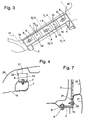
- Fig. 3 shows a plan view of the fender carrier 1 and the fender bank 7, where it is anchored by the screws 8.
- On the upper sides 13 of the buffer elements 12 are each two openings, an elongated opening 14 and a round opening 15 can be seen. These openings define the position of the fender with respect to the fender carrier 1 in a manner to be described in more detail later. Since the fender carrier 1 unambiguously defines the position of the fender, it can be ensured by aligning the fender carrier 1 with respect to adjacent body parts that the fender carrier 1 when mounted later, it will be correctly positioned with respect to these body panels.
- the fender carrier 1 is aligned so that there is a desired gap width between this and the door during the later assembly of the fender. Since the screws 8 enforce the slots 6 with a game in the transverse direction, it is possible to move the fender carrier 1 in dimensions transversely and to rotate about a vertical axis.
- a Fig. 3 partly as dot-dashed Outline indicated hoods 17 are two opposing fender carrier 1 aligned so that in Fig. 3 With 18 designated corners of their bracket 2 form exactly a symmetrical trapezoidal of the hood gauge 17 predetermined shape. The fixed in the position thus obtained fender carrier 1 then serve as a reference for the assembly of a hood, not shown.
- Fig. 4 shows a schematic partial section through the fully assembled body along in Fig. 3 with IV designated level.
- the section extends through a slot 6 and shows the screw 8 received therein, which fixes the bracket 2 to the fender bank 7.
- Below the fender bank 7, a wall 19 of a wheel well can be seen.
- the polypropylene molded fender 20 has a horizontal edge strip 21 resting on the buffer members 12.
- the edge strip 21 is bounded by a vertical stop edge 22. This stop edge 22 may extend in sections or preferably continuously along the entire edge strip 21.
- the edge strip 21 obscures the view of a fitter on the fender carrier 1, which in itself makes the exact placement of the fender 20 difficult.
- Fig. 5 illustrates that one too Fig. 4 parallel section along the in Fig. 3 with V designated level shows.
- Fig. 7 shows a section through the lower end of the front arm 3 of the fender carrier 1 and its surroundings on the fully assembled vehicle body.
- a screw 8 which passes through the slot 6 of the tab 5, fixes the lower end of the arm 3 to a wall of the wheel arch XX or other suitable part of the body shell.
- a lower edge region of the fender 20 lies, hidden by a bumper cover 27, at the lower end of the arm 3. Like the edge strip 21, this lower edge region carries a latching projection 24 which engages in a corresponding opening of the arm 3 and thereby defines a position of the fender 20 in which an adjacent opening 15 of the arm 3 is aligned with an opening of the fender 20. so that the fender can be fastened by a clip 26 inserted through both openings.
- Fig. 8 shows in one too Fig. 7 a screw 8, which passes through the slot 6 of the tab 5, fixes the lower end of the arm 4 to a wall of the sill 10 (this item number is missing in the picture) or another suitable part of the body shell ,
- the fender 20 is angled at its lower edge and extends over the tab 5. It is invisible to a viewer standing next to the vehicle by a clip 26 which is inserted from below into aligned openings of the edge region and the flap 5.
- the fender carrier 1 is for the sole purpose of attaching the plate-like fender 20 to the vehicle body.
- a fender may also be pre-assembled with other components of the vehicle, such as in particular a headlight or a headlight socket, to a module which is placed and fastened as a unit to the fender carrier.
- other components of the vehicle such as in particular a headlight or a headlight socket
- Fig. 9 one too Fig. 2 analogous view, in which a socket 28 is integrated for a headlight in the fender carrier 1.
Landscapes
- Engineering & Computer Science (AREA)
- Mechanical Engineering (AREA)
- Chemical & Material Sciences (AREA)
- Combustion & Propulsion (AREA)
- Transportation (AREA)
- Body Structure For Vehicles (AREA)
- Automobile Manufacture Line, Endless Track Vehicle, Trailer (AREA)
Abstract
Description
Die vorliegende Erfindung betrifft eine Kraftfahrzeugkarosserie und ein Verfahren zu deren Montage.The present invention relates to a motor vehicle body and a method of assembling the same.
Bei den gegenwärtigen Kraftfahrzeugkarosserien bestehen die tragenden Teile des Rohbaus sowie die Teile der Außenhaut wie etwa Front- und Heckklappe, Türen, Kotflügel aus Metall und werden zusammengebaut, bevor die Karosserie als Ganzes lackiert wird. Um das Gewicht eines Fahrzeuges und damit dessen Treibstoffverbrauch zu verringern, ist es an sich interessant, Teile der Außenhaut aus Kunststoff zu fertigen. Dabei tritt jedoch das Problem auf, dass aus preiswerten Kunststoffen gefertigte Außenhautteile sich meist nicht dafür eignen, zusammen mit den Metallteilen der Karosserie in einem Arbeitsgang lackiert zu werden, sei es, weil sie nicht gegen die im Lackierprozess auftretenden hohen Temperaturen in der Größenordnung von 200°C beständig sind, weil sie mit verwendeten Lösungsmitteln inkompatibel sind, oder aus anderen Gründen. Bei Stoßfängerverkleidungen, die bei gegenwärtigen Kraftfahrzeugkarosserien bereits verbreitet aus Kunststoff gefertigt werden, ist eine Montage nach dem Lackieren möglich, da ihre Position bei der Montage so mit der Position der bereits vorhandenen Metallteile abgeglichen werden kann, dass sich zwischen diesen Metallteilen und der Stoßfängerverkleidung gleichmäßig breite Fugen ergeben. Bei den Kotflügeln ist dies im Allgemeinen nicht der Fall. Deren Montage erfolgt üblicherweise in zwei Schritten, wobei in einem ersten Schritt eine an eine bereits montierte Tür der Karosserie angrenzende Kante des Kotflügels in Bezug auf die Tür so ausgerichtet wird, dass sich zwischen beiden eine gleichmäßige Spaltbreite ergibt und der Kotflügel das Öffnen der Tür nicht behindert, gefolgt von einem Schwenken der zu einer gleichen Klappe der Karosserie benachbarten Kotflügel derart, dass die Klappe zwischen beiden mit gleichmäßiger Spaltbreite Platz findet. Um die Klappe montieren zu können, müssen demzufolge die ihr benachbarten Kotflügel vorher montiert sein. Wenn die Klappe dem Lackierprozess unterzogen werden soll, die Kotflügel hierfür aber nicht geeignet sind, müssten sie nach Anbringung der Klappe wieder entfernt und nach der Lackierung erneut montiert werden, was den Fertigungsaufwand in unzweckmäßiger Weise erhöht.In the current motor vehicle bodies, the load-bearing parts of the shell and the parts of the outer skin such as front and tailgate, doors, fenders are made of metal and are assembled before the body is painted as a whole. In order to reduce the weight of a vehicle and thus its fuel consumption, it is interesting in itself to manufacture parts of the outer skin made of plastic. However, the problem arises that made of inexpensive plastic outer skin parts are usually not suitable to be painted together with the metal parts of the body in one operation, either because they are not against the occurring in the painting process high temperatures in the order of 200 ° C are resistant because they are incompatible with solvents used, or for other reasons. In bumper panels, which are already commonly made of plastic in current motor vehicle bodies, a mounting after painting is possible because their position during assembly can be compared with the position of the existing metal parts, that evenly between these metal parts and the bumper cover Giving joints. For the fenders this is generally not the case. Their installation is usually carried out in two steps, wherein in a first step adjacent to an already mounted door of the body edge of the fender is aligned with respect to the door so that there is a uniform gap width between the two and the fender does not open the door obstructed, followed by a pivoting of the fender adjacent to a same flap of the body such that the flap between two with uniform gap width fits. Consequently, in order to mount the flap, its adjacent fenders must be mounted beforehand. If the flap is to be subjected to the painting process, but the fenders are not suitable for this purpose, they would have to be removed after installation of the flap and reassembled after painting, which increases the manufacturing effort inappropriately.
Aus
Aufgabe der vorliegenden Erfindung ist, eine Kraftfahrzeugkarosserie und ein Montageverfahren dafür anzugeben, die es auf wirtschaftliche Weise ermöglichen, Kotflügel zu verbauen, die für eine Lackierung zusammen mit dem Rohbau der Karosserie nicht geeignet sind.The object of the present invention is to provide a motor vehicle body and a mounting method therefor, which make it possible in an economical way to obstruct fenders, which are not suitable for painting together with the body shell of the body.
Die Aufgabe wird gelöst durch eine Kraftfahrzeugskarosserie mit den Merkmalen des Anspruchs 1 sowie durch ein Verfahren mit den Merkmalen des Anspruchs 11. Um dem Kotflügel an verschiedenen, weist auseinanderliegenden Punkten fixieren zu können, umfasst der Kotflügelträger zweckmäßigerweise einen ein Radhaus des Fahrzeuges überbrückenden Bügel und zwei sich von dem Bügel aus beiderseits des Radhauses abwärts erstreckende Arme. Die erfindungsgemäße Karosserie ermöglicht ein Montageverfahren, bei dem an dem bereitgestellten Rohbau zunächst der Kotflügelträger ausgerichtet und befestigt wird und, nachdem der Rohbau zusammen mit dem Kotflügelträger lackiert worden ist, der Kotflügel an einer durch den Kotflügelträger definierten Stelle montiert wird.The object is achieved by a motor vehicle body having the features of
D.h. anstelle des Kotflügels wird zunächst stellvertretend für diesen nur der Kotflügelträger montiert, wobei die Montage des Kotflügelträgers so wie herkömmlicherweise die des Kotflügels selber so erfolgen kann, dass eine gewünschte Spaltbreite zwischen dem zwar noch nicht montierten, aber in seiner Position durch den Kotflügelträger definierten Kotflügel und angrenzenden Teilen der Außenhaut gewährleistet ist. So kann insbesondere nach Montage der Kotflügelträger, aber vor Montage der Kotflügel selbst, eine Haube korrekt montiert und justiert werden, die später von den von den Kotflügelträgern getragenen Kotflügeln flankiert ist.That is, instead of the mudguard, only the mudguard carrier is initially mounted on behalf of this, the assembly of the mudguard carrier as conventionally that of the mudguard itself can be such that a desired gap width between the not yet mounted, but defined in its position by the fender carrier fender and adjacent parts of the outer skin is ensured. Thus, in particular after assembly of the fender carrier, but before assembly of the fender itself, a hood can be correctly mounted and adjusted, which is flanked later by the fenders worn by the fender carriers.
Zweckmäßigerweise sind Kotflügel und Kotflügelträger so ausgelegt, dass der Kotflügel an dem Kotflügelträger nur in einer einzigen Stellung befestigbar ist.Conveniently, fenders and fender carrier are designed so that the fender can be fastened to the fender carrier only in a single position.
Damit bei der Montage des Kotflügels diese einzige Stellung leicht gefunden werden kann, weisen der Kotflügelträger und der Kotflügel vorzugsweise zusammenwirkende Führungsoberflächen auf, die in Kontakt miteinander eine Bewegung des noch unbefestigten Kotflügels gegen den Kotflügelträger in zwei Freiheitsgraden führen, wobei durch diese Bewegung besagte einzige Stellung erreichbar ist.Thus, when mounting the fender, this single position can be easily found, the fender carrier and the fender preferably on cooperating guide surfaces, which in contact with each other, a movement of the still unfastened fender against the fender carrier in two degrees of freedom, said by said movement said single position is reachable.
Um das Auffinden der einzigen Stellung weiter zu erleichtern, ist zweckmäßigerweise eine der Führungsoberflächen eine ebene Fläche, die eine zweite ebene Fläche kreuzt. Die Linie, in der sich die zwei ebenen Flächen kreuzen, bildet einerseits eine leicht zu findende Bezugsmarke für die Positionierung des Kotflügels und zum anderen gibt sie eine bevorzugte Bewegungsrichtung vor, in welcher der Kotflügel zu der einzigen Stellung bewegt werden kann.To further facilitate locating the single position, one of the guide surfaces is conveniently a flat surface that intersects a second planar surface. The line in which the two flat surfaces intersect forms on the one hand an easy-to-find fiducial for the positioning of the fender and, on the other hand, provides a preferred direction of movement in which the fender can be moved to the single position.
Um diese einzige Stellung eindeutig zu markieren, hat von Kotflügelträger und Kotflügel vorzugsweise der eine wenigstens eine Öffnung und der andere einen Vorsprung, der bei der fertig montierten Fahrzeugkarosserie formschlüssig in die Öffnung eingesteckt ist.In order to clearly mark this single position, the fender carrier and the fender preferably have at least one opening and the other has a projection which is positively inserted into the opening in the fully assembled vehicle body.
Der Kotflügelträger ist am Rohbau vorzugsweise durch Schrauben befestigt, die sich im Wesentlichen in Längsrichtung der Karosserie erstreckende Langlöcher des Kotflügelträgers durchsetzen. Diese Langlöcher erzeugen ein Spiel des Kotflügelträgers in der Fahrzeuglängsrichtung, das insbesondere eine Ausrichtung des Kotflügels in Bezug auf eine benachbarte Tür ermöglicht. Indem die Schrauben die Langlöcher ferner mit einem Spiel in Querrichtung der Karosserie durchsetzen, wird darüber hinaus die Möglichkeit geschaffen, den Kotflügelträger beim Ausrichten zu drehen oder in der Querrichtung zu verschieben.The fender carrier is preferably attached to the shell by screws, which prevail extending substantially in the longitudinal direction of the body extending slots of the fender carrier. These slots create a play of the fender carrier in the vehicle longitudinal direction, in particular an orientation of the fender in relation to an adjacent door. Further, by the screws passing through the slots with a play in the transverse direction of the body, the possibility is created to rotate the fuselage support during alignment or to move in the transverse direction.
Als Schutzmaßnahme für den Fall eines Zusammenstoßes mit einem Fußgänger (Pedestrian Protection) kann vorgesehen sein, dass ein oberer Bereich des Kotflügels an dem Kotflügelträger über wenigstens ein vertikal und/oder in Fahrtrichtung nachgiebiges Pufferelement abgestützt ist.As a protective measure in the event of a collision with a pedestrian (Pedestrian Protection) may be provided that an upper portion of the fender is supported on the fender carrier via at least one vertically and / or resilient in the direction of travel buffer element.
Der Kotflügel kann Teil eines von dem Kotflügelträger gehaltenen Kotflügelmoduls sein, das ferner wenigstens einen Scheinwerfer oder eine Scheinwerferfassung umfasst.The fender may be part of a fender module held by the fender carrier which further comprises at least one headlight or a headlight socket.
Alternativ kann ein Scheinwerfer oder eine Scheinwerferfassung in den Kotflügelträger selbst integriert sein.Alternatively, a headlight or a headlight socket can be integrated into the fender carrier itself.
Der Kotflügel kann aus einem thermoplastischen Kunststoff, insbesondere aus Polypropylen, gefertigt sein.The fender may be made of a thermoplastic material, in particular of polypropylene.
Weitere Merkmale und Vorteile der Erfindung ergeben sich aus der nachfolgenden Beschreibung von Ausführungsbeispielen unter Bezugnahme auf die beigefügten Figuren. Es zeigen:
- Fig. 1
- eine perspektivische Ansicht eines Kotflügelträgers mit Pufferelementen gemäß der vorliegenden Erfindung;
- Fig. 2
- den Kotflügelträger aus
Fig. 1 montiert an einem Karosserierohbau; - Fig.3
- eine Draufsicht auf einen oberen Abschnitt des Kotflügelträgers;
- Fig. 4
- einen Schnitt entlang der in
Fig. 3 mit IV bezeichneten Ebene - Fig. 5
- einen Schnitt entlang der in
Fig. 3 mit V bezeichneten Ebene; - Fig. 6
- eine perspektivische Ansicht eines Bruchstücks des Kotflügels;
- Fig. 7
- einen Schnitt durch den vorderen Arm des Kotflügelträgers, am Karosserierohbau befestigt und mit einem daran montierten Kotflügel;
- Fig. 8
- einen Schnitt durch den hinteren Arm des Kotflügelträgers, ebenfalls am Karosserierohbau befestigt und mit daran montiertem Kotflügel; und
- Fig. 9
- eine zu
Fig. 2 analoge Ansicht eines abgewandelten Kotflügelträgers.
- Fig. 1
- a perspective view of a fender carrier with buffer elements according to the present invention;
- Fig. 2
- the fender carrier
Fig. 1 mounted on a body shell; - Figure 3
- a plan view of an upper portion of the fender carrier;
- Fig. 4
- a cut along in
Fig. 3 with IV designated level - Fig. 5
- a cut along in
Fig. 3 level labeled V; - Fig. 6
- a perspective view of a fragment of the fender;
- Fig. 7
- a cut through the front arm the fender carrier, attached to the body shell and with a mounted fender;
- Fig. 8
- a section through the rear arm of the fender carrier, also attached to the body shell and mounted thereon fender; and
- Fig. 9
- one too
Fig. 2 analogous view of a modified fender carrier.
Der in
Der Bügel 2 und die Arme 3, 4 sind hier einstückig aus einem hitzebeständigen Kunststoff spritzgeformt. Zur Versteifung sind der Bügel 2 und die Arme 3 an ihren Rändern jeweils durch umlaufende Rippen 11 verstärkt. Alternativ könnten der Bügel 2 und die Arme 3, 4 auch aus Metall gefertigt sein.The
Zwischen je zwei der Langlöcher 6 trägt der Bügel 2 an seiner Oberseite jeweils ein Pufferelement 12, hier in Form einer Hülse von sechseckigem Querschnitt mit einer Oberseite 13, die vorgesehen ist, um den in
In dieser verankerten Stellung fluchten die Öffnungen 15 und 23, und durch einfaches Hindurchstecken eines mit Widerhaken besetzten Clips 26 (siehe
Bei der obigen Beschreibung wurde angenommen, dass der Kotflügelträger 1 ausschließlich der Befestigung des plattenartigen Kotflügels 20 an der Fahrzeugkarosserie dient. Selbstverständlich kann ein solcher Kotflügel auch mit anderen Bauteilen des Fahrzeuges, wie etwa insbesondere einem Scheinwerfer oder einer Scheinwerferfassung, zu einem Modul vormontiert sein, welches als eine Einheit an dem Kotflügelträger platziert und befestigt wird. Genauso ist es möglich, derartige Bauteile mit dem Kotflügelträger selber zu einem Modul zusammenzufassen; im einen wie im anderen Falle ist die Position der zusätzlichen Bauteile in Bezug auf den Kotflügel eindeutig festgelegt und in Bezug auf benachbarte Karosserieteile über den Kotflügelträger 1 ausrichtbar. Zur Veranschaulichung zeigt
- Kotflügelträgerfender bracket
- 11
- Bügelhanger
- 22
- Armepoor
- 3, 43, 4
- Lascheflap
- 55
- Langlöcherslots
- 66
- Kotflügelbankfender
- 77
- Schraubenscrew
- 88th
- Längsträgerslongitudinal member
- 99
- Schwellersill
- 1010
- Rippenribs
- 1111
- Pufferelementbuffer element
- 1212
- Oberseitetop
- 1313
- Öffnungopening
- 14, 1514, 15
- Türrahmendoorframe
- 1616
- Haubenlehrehood teaching
- 1717
- Eckecorner
- 1818
- Wandwall
- 1919
- Kotflügelfender
- 2020
- Randstreifenedge strips
- 2121
- Anschlagflankestop flank
- 2222
- Öffnungopening
- 2323
- Vorsprunghead Start
- 2424
- Rasthakenlatch hook
- 2525
- Clipclip
- 2626
- Stoßfängerverkleidungbumper fascia
- 2727
- Scheinwerferfassungheadlamp shell
- 2828
Claims (15)
- A motor-vehicle body, comprising a paint-resistant carcass and at least one mudguard (20) which is made of a material that is not suitable for joint painting with the carcass and which is held on the carcass by a mudguard support (1) which is made from a paint-resistant material and is adjustable with respect to the carcass, which mudguard can be fastened to the mudguard support (1) in a single position, wherein the mudguard support (1) comprises a holder (2) bridging a wheel house (19) and two arms (3, 4) extending downwardly from the holder (2) on either side of the wheel house (19).
- A motor-vehicle body according to claim 1, characterized in that the mudguard support (1) and the mudguard (20) comprise cooperating guide surfaces (13; 21, 22) which when in contact with each other guide a movement of the unfastened mudguard (20) against the mudguard support (1) in two degrees of freedom, by which the only position can be reached.
- A motor-vehicle body according to claim 2, characterized in that one of the guide surfaces (21; 22) is a planar surface which crosses a second planar surface (22; 21).
- A motor-vehicle body according to one of the preceding claims, characterized in that concerning the mudguard support (1) and the mudguard (20) the one comprises at least one opening (14) and the other comprises a projection (24) inserted in an interlocking manner in the opening (14).
- A motor-vehicle body according to one of the preceding claims, characterized in that the mudguard support (1) is fastened to the carcass by screws (8) which penetrate oblong holes (6) of the mudguard support (1), which oblong holes extend substantially in the longitudinal direction of the body.
- A motor-vehicle body according to claim 5, characterized in that the screws (8) penetrate the oblong holes (6) with play in the transverse direction of the body.
- A motor-vehicle body according to one of the preceding claims, characterized in that the mudguard (20) rests on the holder (2) via at least one buffer element (12) which is resilient in the vertical direction and/or in the direction of travel.
- A motor-vehicle body according to one of the preceding claims, characterized in that the mudguard is part of a mudguard module which is held by the mudguard support and which further comprises at least one headlight or a headlight socket.
- A motor-vehicle body according to one of the claims 1 to 7, characterized in that at least one headlight or headlight socket (28) is integrated in the mudguard support (1).
- A motor-vehicle body according to one of the preceding claims, characterized in that the mudguard (20) is made of a thermoplastic material.
- A method for mounting a motor-vehicle body, especially a motor-vehicle body according to one of the preceding claims, with the following steps:a) provision of a carcass;b) adjusting and final fastening of a mudguard support (1) to the carcass;e) painting the carcass together with the mudguard support (1) ;f) mounting of a mudguard (20) at a position defined by themudguard holder (1).
- A method according to claim 11, characterized in that the adjustment in step b) comprises the following partial steps:b1) adjustment of the mudguard support (1) with respect to a door;b2) adjustment of the mudguard support (1) with respect to a gauge (17) of the hood.
- A method according to claim 11 or 12, characterized in that it further comprises the following steps:c) placement of a gauge on the adjusted and fastened mudguard support (1);d) adjusting and placing a hood by means of the gauge placed in step c).
- A method according to one of the claims 11 to 13, characterized in that if the mudguard support (1) and the mudguard (20) comprise cooperating guide surfaces (13; 21, 22) which in contact with one another guide a movement of the unfastened mudguard (20) towards the mudguard support (1) in two degrees of freedom, the step f) comprises the displacement of the mudguard (20) towards the mudguard support (1) up to the defined position when the guide surfaces (13; 21, 22) touch one another.
- A method according to one of the claims 11 to 14, characterized in that if with respect to the mudguard carrier (1) and the mudguard (20) the one comprises an opening (14) and the other a projection (24) that can be inserted in an interlocking manner in the opening (14), the step f) comprises the insertion of the projection (24) into the opening (14).
Applications Claiming Priority (1)
| Application Number | Priority Date | Filing Date | Title |
|---|---|---|---|
| DE102006053015A DE102006053015A1 (en) | 2006-11-10 | 2006-11-10 | Motor vehicle body and assembly method therefor |
Publications (2)
| Publication Number | Publication Date |
|---|---|
| EP1920998A1 EP1920998A1 (en) | 2008-05-14 |
| EP1920998B1 true EP1920998B1 (en) | 2010-12-01 |
Family
ID=39032389
Family Applications (1)
| Application Number | Title | Priority Date | Filing Date |
|---|---|---|---|
| EP07021163A Not-in-force EP1920998B1 (en) | 2006-11-10 | 2007-10-30 | Motor vehicle bodywork and assembly method therefor |
Country Status (3)
| Country | Link |
|---|---|
| EP (1) | EP1920998B1 (en) |
| AT (1) | ATE490155T1 (en) |
| DE (2) | DE102006053015A1 (en) |
Families Citing this family (10)
| Publication number | Priority date | Publication date | Assignee | Title |
|---|---|---|---|---|
| FR2929583B1 (en) * | 2008-04-08 | 2010-10-15 | Renault Sas | ARRANGEMENT FOR FIXING A WING OF A MOTOR VEHICLE |
| EP2436565A1 (en) * | 2010-10-01 | 2012-04-04 | Volvo Car Corporation | Deformation control bracket |
| DE102010060800A1 (en) * | 2010-11-25 | 2012-05-31 | Dr. Ing. H.C. F. Porsche Aktiengesellschaft | Fender arrangement for motor vehicle, has C-shaped deformation element with of upper leg and upper half-shell that are connected to fender, and lower leg and lower half-shell that are connected to body of vehicle |
| DE102011106951A1 (en) | 2011-07-08 | 2013-01-10 | GM Global Technology Operations LLC (n. d. Gesetzen des Staates Delaware) | Automotive body |
| KR101361372B1 (en) | 2012-06-18 | 2014-02-10 | 기아자동차주식회사 | Device for assembling fender panel of vehicle |
| DE102013014723A1 (en) * | 2013-09-05 | 2015-03-05 | GM Global Technology Operations LLC (n. d. Ges. d. Staates Delaware) | Fender holding arrangement of a vehicle body |
| FR3086918B1 (en) | 2018-10-03 | 2022-05-27 | Psa Automobiles Sa | VEHICLE HAVING AT LEAST ONE MULTIFUNCTIONAL WING LOWER SUPPORT |
| FR3097188B1 (en) * | 2019-06-12 | 2021-06-18 | Psa Automobiles Sa | REINFORCEMENT MEANS FOR A MOTOR VEHICLE FRONT STRUCTURE |
| CN115339550B (en) * | 2022-08-24 | 2023-06-09 | 上汽大众汽车有限公司 | Frameless car door detection device |
| CN115556693B (en) * | 2022-10-09 | 2024-05-17 | 阿维塔科技(重庆)有限公司 | Coupling assembling and car of front bumper and fender |
Citations (1)
| Publication number | Priority date | Publication date | Assignee | Title |
|---|---|---|---|---|
| EP1398249A1 (en) * | 2002-09-13 | 2004-03-17 | Renault s.a.s. | Multi-purpose support for positioning and attaching a body part of a car |
Family Cites Families (9)
| Publication number | Priority date | Publication date | Assignee | Title |
|---|---|---|---|---|
| JPS5853571A (en) * | 1981-09-28 | 1983-03-30 | Nissan Motor Co Ltd | Fitting method of front fender panel |
| JPS63222951A (en) * | 1987-03-11 | 1988-09-16 | Nissan Motor Co Ltd | Body structure of vehicle |
| WO1998018670A1 (en) | 1996-10-30 | 1998-05-07 | Volkswagen Aktiengesellschaft | Cpkd car body |
| KR100417942B1 (en) * | 2000-03-31 | 2004-02-11 | 도요타지도샤가부시키가이샤 | Fender assembly for a vehicle |
| JP3863715B2 (en) | 2000-10-06 | 2006-12-27 | 株式会社パイオラックス | Resin panel fixing structure |
| DE10244455A1 (en) | 2002-09-24 | 2004-05-13 | Volkswagen Ag | Fender structure on motor vehicles |
| JP4210834B2 (en) * | 2002-11-22 | 2009-01-21 | トヨタ自動車株式会社 | Resin fender panel position adjustment method and resin fender panel position adjustment structure |
| US20060157350A1 (en) * | 2004-12-22 | 2006-07-20 | Williamson David T | Toughened polyester compositions |
| DE102005006306A1 (en) * | 2005-02-11 | 2006-08-17 | Rehau Ag + Co | Kit for mounting a vehicle trim element |
-
2006
- 2006-11-10 DE DE102006053015A patent/DE102006053015A1/en not_active Withdrawn
-
2007
- 2007-10-30 EP EP07021163A patent/EP1920998B1/en not_active Not-in-force
- 2007-10-30 DE DE502007005826T patent/DE502007005826D1/en active Active
- 2007-10-30 AT AT07021163T patent/ATE490155T1/en active
Patent Citations (1)
| Publication number | Priority date | Publication date | Assignee | Title |
|---|---|---|---|---|
| EP1398249A1 (en) * | 2002-09-13 | 2004-03-17 | Renault s.a.s. | Multi-purpose support for positioning and attaching a body part of a car |
Also Published As
| Publication number | Publication date |
|---|---|
| ATE490155T1 (en) | 2010-12-15 |
| DE102006053015A1 (en) | 2008-05-15 |
| EP1920998A1 (en) | 2008-05-14 |
| DE502007005826D1 (en) | 2011-01-13 |
Similar Documents
| Publication | Publication Date | Title |
|---|---|---|
| EP1920998B1 (en) | Motor vehicle bodywork and assembly method therefor | |
| EP1336551B1 (en) | Wheel guard assembly for a vehicle | |
| DE69908529T2 (en) | Method for manufacturing a structure for the front of motor vehicles, and structure for the front of motor vehicles produced by this method | |
| DE19919505A1 (en) | Vehicle roof with inserted roof module and assembly process for it | |
| DE102013018079A1 (en) | Hinge for a motor vehicle | |
| DE102012023674A1 (en) | Motor vehicle with modular bodywork | |
| DE102016010366B4 (en) | VEHICLE FRONT STRUCTURE | |
| DE102005021724B4 (en) | Bumper device for a vehicle, in particular for a motor vehicle | |
| DE102011106951A1 (en) | Automotive body | |
| DE10359768A1 (en) | vehicle body | |
| EP2559609B1 (en) | Reinforcement frame and method for applying a reinforcement frame in a vehicle body | |
| EP1348585B1 (en) | Displaceable panel for vehicle roof and sliding roof module | |
| DE3817842C2 (en) | ||
| DE102009032603A1 (en) | Body part for a motor vehicle | |
| DE102015115187B4 (en) | An energy absorbing member for a vehicle and a bumper assembly comprising such a member and a bumper cross member | |
| DE102015220978B3 (en) | roof arrangement | |
| EP1600338B1 (en) | Vehicle with deformable energy absorbing member | |
| DE3803136C1 (en) | Device for attaching a motor-vehicle accessory, in particular air-guiding devices, to vehicle bodies | |
| DE102013010490A1 (en) | Front end of a motor vehicle | |
| EP0332846B1 (en) | Radiator grille for motor vehicles | |
| DE102015115741A1 (en) | Bumper system for a motor vehicle | |
| DE102010018470A1 (en) | Rear section for motor vehicle body, has two rear longitudinal carriers, rear base extending between rear longitudinal carriers and rear cross member having profile section connecting rear longitudinal carriers | |
| DE60009465T2 (en) | DEVICE FOR FASTENING A FENDER INTEGRATED TO A BUMPER | |
| DE102009007700B4 (en) | Motor vehicle with a fender | |
| DE19524506A1 (en) | Front wing reinforcing structure in vehicle body |
Legal Events
| Date | Code | Title | Description |
|---|---|---|---|
| PUAI | Public reference made under article 153(3) epc to a published international application that has entered the european phase |
Free format text: ORIGINAL CODE: 0009012 |
|
| AK | Designated contracting states |
Kind code of ref document: A1 Designated state(s): AT BE BG CH CY CZ DE DK EE ES FI FR GB GR HU IE IS IT LI LT LU LV MC MT NL PL PT RO SE SI SK TR |
|
| AX | Request for extension of the european patent |
Extension state: AL BA HR MK RS |
|
| 17P | Request for examination filed |
Effective date: 20081114 |
|
| AKX | Designation fees paid |
Designated state(s): AT BE BG CH CY CZ DE DK EE ES FI FR GB GR HU IE IS IT LI LT LU LV MC MT NL PL PT RO SE SI SK TR |
|
| 17Q | First examination report despatched |
Effective date: 20090109 |
|
| GRAP | Despatch of communication of intention to grant a patent |
Free format text: ORIGINAL CODE: EPIDOSNIGR1 |
|
| GRAS | Grant fee paid |
Free format text: ORIGINAL CODE: EPIDOSNIGR3 |
|
| GRAA | (expected) grant |
Free format text: ORIGINAL CODE: 0009210 |
|
| AK | Designated contracting states |
Kind code of ref document: B1 Designated state(s): AT BE BG CH CY CZ DE DK EE ES FI FR GB GR HU IE IS IT LI LT LU LV MC MT NL PL PT RO SE SI SK TR |
|
| REG | Reference to a national code |
Ref country code: GB Ref legal event code: FG4D Free format text: NOT ENGLISH |
|
| REG | Reference to a national code |
Ref country code: CH Ref legal event code: EP |
|
| REG | Reference to a national code |
Ref country code: IE Ref legal event code: FG4D |
|
| REF | Corresponds to: |
Ref document number: 502007005826 Country of ref document: DE Date of ref document: 20110113 Kind code of ref document: P |
|
| REG | Reference to a national code |
Ref country code: NL Ref legal event code: VDEP Effective date: 20101201 |
|
| PG25 | Lapsed in a contracting state [announced via postgrant information from national office to epo] |
Ref country code: LT Free format text: LAPSE BECAUSE OF FAILURE TO SUBMIT A TRANSLATION OF THE DESCRIPTION OR TO PAY THE FEE WITHIN THE PRESCRIBED TIME-LIMIT Effective date: 20101201 |
|
| LTIE | Lt: invalidation of european patent or patent extension |
Effective date: 20101201 |
|
| REG | Reference to a national code |
Ref country code: DE Ref legal event code: R081 Ref document number: 502007005826 Country of ref document: DE Owner name: GM GLOBAL TECHNOLOGY OPERATIONS LLC (N. D. GES, US Free format text: FORMER OWNER: GM GLOBAL TECHNOLOGY OPERATIONS, INC., DETROIT, MICH., US Effective date: 20110323 |
|
| PG25 | Lapsed in a contracting state [announced via postgrant information from national office to epo] |
Ref country code: LV Free format text: LAPSE BECAUSE OF FAILURE TO SUBMIT A TRANSLATION OF THE DESCRIPTION OR TO PAY THE FEE WITHIN THE PRESCRIBED TIME-LIMIT Effective date: 20101201 Ref country code: BG Free format text: LAPSE BECAUSE OF FAILURE TO SUBMIT A TRANSLATION OF THE DESCRIPTION OR TO PAY THE FEE WITHIN THE PRESCRIBED TIME-LIMIT Effective date: 20110301 Ref country code: CY Free format text: LAPSE BECAUSE OF FAILURE TO SUBMIT A TRANSLATION OF THE DESCRIPTION OR TO PAY THE FEE WITHIN THE PRESCRIBED TIME-LIMIT Effective date: 20101201 Ref country code: NL Free format text: LAPSE BECAUSE OF FAILURE TO SUBMIT A TRANSLATION OF THE DESCRIPTION OR TO PAY THE FEE WITHIN THE PRESCRIBED TIME-LIMIT Effective date: 20101201 Ref country code: FI Free format text: LAPSE BECAUSE OF FAILURE TO SUBMIT A TRANSLATION OF THE DESCRIPTION OR TO PAY THE FEE WITHIN THE PRESCRIBED TIME-LIMIT Effective date: 20101201 Ref country code: SI Free format text: LAPSE BECAUSE OF FAILURE TO SUBMIT A TRANSLATION OF THE DESCRIPTION OR TO PAY THE FEE WITHIN THE PRESCRIBED TIME-LIMIT Effective date: 20101201 Ref country code: SE Free format text: LAPSE BECAUSE OF FAILURE TO SUBMIT A TRANSLATION OF THE DESCRIPTION OR TO PAY THE FEE WITHIN THE PRESCRIBED TIME-LIMIT Effective date: 20101201 |
|
| REG | Reference to a national code |
Ref country code: IE Ref legal event code: FD4D |
|
| PG25 | Lapsed in a contracting state [announced via postgrant information from national office to epo] |
Ref country code: GR Free format text: LAPSE BECAUSE OF FAILURE TO SUBMIT A TRANSLATION OF THE DESCRIPTION OR TO PAY THE FEE WITHIN THE PRESCRIBED TIME-LIMIT Effective date: 20110302 |
|
| REG | Reference to a national code |
Ref country code: CH Ref legal event code: PFA Owner name: GM GLOBAL TECHNOLOGY OPERATIONS LLC Free format text: GM GLOBAL TECHNOLOGY OPERATIONS, INC.#300 RENAISSANCE CENTER#DETROIT, MI 48265-3000 (US) -TRANSFER TO- GM GLOBAL TECHNOLOGY OPERATIONS LLC#300 RENAISSANCE CENTER#DETROIT, MI 48265-3000 (US) |
|
| RAP2 | Party data changed (patent owner data changed or rights of a patent transferred) |
Owner name: GM GLOBAL TECHNOLOGY OPERATIONS LLC |
|
| PG25 | Lapsed in a contracting state [announced via postgrant information from national office to epo] |
Ref country code: IS Free format text: LAPSE BECAUSE OF FAILURE TO SUBMIT A TRANSLATION OF THE DESCRIPTION OR TO PAY THE FEE WITHIN THE PRESCRIBED TIME-LIMIT Effective date: 20110401 Ref country code: EE Free format text: LAPSE BECAUSE OF FAILURE TO SUBMIT A TRANSLATION OF THE DESCRIPTION OR TO PAY THE FEE WITHIN THE PRESCRIBED TIME-LIMIT Effective date: 20101201 Ref country code: ES Free format text: LAPSE BECAUSE OF FAILURE TO SUBMIT A TRANSLATION OF THE DESCRIPTION OR TO PAY THE FEE WITHIN THE PRESCRIBED TIME-LIMIT Effective date: 20110312 Ref country code: CZ Free format text: LAPSE BECAUSE OF FAILURE TO SUBMIT A TRANSLATION OF THE DESCRIPTION OR TO PAY THE FEE WITHIN THE PRESCRIBED TIME-LIMIT Effective date: 20101201 Ref country code: IE Free format text: LAPSE BECAUSE OF FAILURE TO SUBMIT A TRANSLATION OF THE DESCRIPTION OR TO PAY THE FEE WITHIN THE PRESCRIBED TIME-LIMIT Effective date: 20101201 Ref country code: PT Free format text: LAPSE BECAUSE OF FAILURE TO SUBMIT A TRANSLATION OF THE DESCRIPTION OR TO PAY THE FEE WITHIN THE PRESCRIBED TIME-LIMIT Effective date: 20110401 |
|
| PG25 | Lapsed in a contracting state [announced via postgrant information from national office to epo] |
Ref country code: PL Free format text: LAPSE BECAUSE OF FAILURE TO SUBMIT A TRANSLATION OF THE DESCRIPTION OR TO PAY THE FEE WITHIN THE PRESCRIBED TIME-LIMIT Effective date: 20101201 Ref country code: RO Free format text: LAPSE BECAUSE OF FAILURE TO SUBMIT A TRANSLATION OF THE DESCRIPTION OR TO PAY THE FEE WITHIN THE PRESCRIBED TIME-LIMIT Effective date: 20101201 Ref country code: SK Free format text: LAPSE BECAUSE OF FAILURE TO SUBMIT A TRANSLATION OF THE DESCRIPTION OR TO PAY THE FEE WITHIN THE PRESCRIBED TIME-LIMIT Effective date: 20101201 |
|
| PLBE | No opposition filed within time limit |
Free format text: ORIGINAL CODE: 0009261 |
|
| STAA | Information on the status of an ep patent application or granted ep patent |
Free format text: STATUS: NO OPPOSITION FILED WITHIN TIME LIMIT |
|
| PG25 | Lapsed in a contracting state [announced via postgrant information from national office to epo] |
Ref country code: DK Free format text: LAPSE BECAUSE OF FAILURE TO SUBMIT A TRANSLATION OF THE DESCRIPTION OR TO PAY THE FEE WITHIN THE PRESCRIBED TIME-LIMIT Effective date: 20101201 |
|
| 26N | No opposition filed |
Effective date: 20110902 |
|
| REG | Reference to a national code |
Ref country code: DE Ref legal event code: R097 Ref document number: 502007005826 Country of ref document: DE Effective date: 20110902 |
|
| PG25 | Lapsed in a contracting state [announced via postgrant information from national office to epo] |
Ref country code: IT Free format text: LAPSE BECAUSE OF FAILURE TO SUBMIT A TRANSLATION OF THE DESCRIPTION OR TO PAY THE FEE WITHIN THE PRESCRIBED TIME-LIMIT Effective date: 20101201 |
|
| BERE | Be: lapsed |
Owner name: GM GLOBAL TECHNOLOGY OPERATIONS, INC. Effective date: 20111031 |
|
| PG25 | Lapsed in a contracting state [announced via postgrant information from national office to epo] |
Ref country code: MC Free format text: LAPSE BECAUSE OF NON-PAYMENT OF DUE FEES Effective date: 20111031 |
|
| REG | Reference to a national code |
Ref country code: CH Ref legal event code: PL |
|
| PG25 | Lapsed in a contracting state [announced via postgrant information from national office to epo] |
Ref country code: LI Free format text: LAPSE BECAUSE OF NON-PAYMENT OF DUE FEES Effective date: 20111031 Ref country code: CH Free format text: LAPSE BECAUSE OF NON-PAYMENT OF DUE FEES Effective date: 20111031 Ref country code: BE Free format text: LAPSE BECAUSE OF NON-PAYMENT OF DUE FEES Effective date: 20111031 |
|
| PG25 | Lapsed in a contracting state [announced via postgrant information from national office to epo] |
Ref country code: MT Free format text: LAPSE BECAUSE OF FAILURE TO SUBMIT A TRANSLATION OF THE DESCRIPTION OR TO PAY THE FEE WITHIN THE PRESCRIBED TIME-LIMIT Effective date: 20101201 |
|
| PG25 | Lapsed in a contracting state [announced via postgrant information from national office to epo] |
Ref country code: LU Free format text: LAPSE BECAUSE OF NON-PAYMENT OF DUE FEES Effective date: 20111030 |
|
| PG25 | Lapsed in a contracting state [announced via postgrant information from national office to epo] |
Ref country code: TR Free format text: LAPSE BECAUSE OF FAILURE TO SUBMIT A TRANSLATION OF THE DESCRIPTION OR TO PAY THE FEE WITHIN THE PRESCRIBED TIME-LIMIT Effective date: 20101201 |
|
| PG25 | Lapsed in a contracting state [announced via postgrant information from national office to epo] |
Ref country code: HU Free format text: LAPSE BECAUSE OF FAILURE TO SUBMIT A TRANSLATION OF THE DESCRIPTION OR TO PAY THE FEE WITHIN THE PRESCRIBED TIME-LIMIT Effective date: 20101201 |
|
| REG | Reference to a national code |
Ref country code: AT Ref legal event code: MM01 Ref document number: 490155 Country of ref document: AT Kind code of ref document: T Effective date: 20121031 |
|
| PG25 | Lapsed in a contracting state [announced via postgrant information from national office to epo] |
Ref country code: AT Free format text: LAPSE BECAUSE OF NON-PAYMENT OF DUE FEES Effective date: 20121031 |
|
| PGFP | Annual fee paid to national office [announced via postgrant information from national office to epo] |
Ref country code: FR Payment date: 20131009 Year of fee payment: 7 Ref country code: DE Payment date: 20131023 Year of fee payment: 7 Ref country code: GB Payment date: 20131030 Year of fee payment: 7 |
|
| REG | Reference to a national code |
Ref country code: DE Ref legal event code: R119 Ref document number: 502007005826 Country of ref document: DE |
|
| GBPC | Gb: european patent ceased through non-payment of renewal fee |
Effective date: 20141030 |
|
| PG25 | Lapsed in a contracting state [announced via postgrant information from national office to epo] |
Ref country code: GB Free format text: LAPSE BECAUSE OF NON-PAYMENT OF DUE FEES Effective date: 20141030 Ref country code: DE Free format text: LAPSE BECAUSE OF NON-PAYMENT OF DUE FEES Effective date: 20150501 |
|
| REG | Reference to a national code |
Ref country code: FR Ref legal event code: ST Effective date: 20150630 |
|
| PG25 | Lapsed in a contracting state [announced via postgrant information from national office to epo] |
Ref country code: FR Free format text: LAPSE BECAUSE OF NON-PAYMENT OF DUE FEES Effective date: 20141031 |