EP1829441B1 - Cooling system and method - Google Patents
Cooling system and method Download PDFInfo
- Publication number
- EP1829441B1 EP1829441B1 EP05817223A EP05817223A EP1829441B1 EP 1829441 B1 EP1829441 B1 EP 1829441B1 EP 05817223 A EP05817223 A EP 05817223A EP 05817223 A EP05817223 A EP 05817223A EP 1829441 B1 EP1829441 B1 EP 1829441B1
- Authority
- EP
- European Patent Office
- Prior art keywords
- coolant
- cooling
- cooling loop
- loop
- subsystem
- Prior art date
- Legal status (The legal status is an assumption and is not a legal conclusion. Google has not performed a legal analysis and makes no representation as to the accuracy of the status listed.)
- Expired - Lifetime
Links
Images


Classifications
-
- H—ELECTRICITY
- H05—ELECTRIC TECHNIQUES NOT OTHERWISE PROVIDED FOR
- H05K—PRINTED CIRCUITS; CASINGS OR CONSTRUCTIONAL DETAILS OF ELECTRIC APPARATUS; MANUFACTURE OF ASSEMBLAGES OF ELECTRICAL COMPONENTS
- H05K7/00—Constructional details common to different types of electric apparatus
- H05K7/20—Modifications to facilitate cooling, ventilating, or heating
- H05K7/20709—Modifications to facilitate cooling, ventilating, or heating for server racks or cabinets; for data centers, e.g. 19-inch computer racks
- H05K7/20763—Liquid cooling without phase change
- H05K7/2079—Liquid cooling without phase change within rooms for removing heat from cabinets
-
- H—ELECTRICITY
- H01—ELECTRIC ELEMENTS
- H01L—SEMICONDUCTOR DEVICES NOT COVERED BY CLASS H10
- H01L23/00—Details of semiconductor or other solid state devices
- H01L23/34—Arrangements for cooling, heating, ventilating or temperature compensation ; Temperature sensing arrangements
- H01L23/46—Arrangements for cooling, heating, ventilating or temperature compensation ; Temperature sensing arrangements involving the transfer of heat by flowing fluids
- H01L23/473—Arrangements for cooling, heating, ventilating or temperature compensation ; Temperature sensing arrangements involving the transfer of heat by flowing fluids by flowing liquids
- H01L23/4735—Jet impingement
-
- H—ELECTRICITY
- H01—ELECTRIC ELEMENTS
- H01L—SEMICONDUCTOR DEVICES NOT COVERED BY CLASS H10
- H01L2924/00—Indexing scheme for arrangements or methods for connecting or disconnecting semiconductor or solid-state bodies as covered by H01L24/00
- H01L2924/0001—Technical content checked by a classifier
- H01L2924/0002—Not covered by any one of groups H01L24/00, H01L24/00 and H01L2224/00
Definitions
- the present invention is directed to cooling assemblies and other apparatus used for removing heat from electronics devices, modules and systems. More particularly, this invention relates to an enhanced cooling system and method for extracting heat from heat generating components of one or more electronics subsystems of one or more electronics racks.
- a cooling system which includes: a coolant distribution unit, the coolant distribution unit comprising a first heat exchanger, a first cooling loop and at least one second cooling loop, the first cooling loop receiving facility coolant and passing at least a portion thereof through the first heat exchanger, the at least one second cooling loop providing system coolant to at least one electronics subsystem, and expelling heat in the first heat exchanger from the at least one electronics subsystem to the facility coolant in the first cooling loop; and at least one thermal dissipation unit associated with the at least one electronics subsystem, each thermal dissipation unit comprising a second heat exchanger, a second cooling loop of the at least one second cooling loop, and a third cooling loop, the second cooling loop providing system coolant to the second heat exchanger, the third cooling loop circulating conditioned coolant within the at least one electronics subsystem and expelling heat in the second heat exchanger from the at least one electronics subsystem to the system coolant in the second cooling loop.
- a cooled electronics system in another aspect, includes at least one electronics rack comprising a plurality of electronics subsystems, and a cooling system.
- the cooling system includes a coolant distribution unit and multiple thermal dissipation units.
- the coolant distribution unit includes a first heat exchanger, a first cooling loop and a plurality of second cooling loops.
- the first cooling loop receives facility coolant and passes at least a portion thereof through the first heat exchanger.
- the plurality of second cooling loops provide system coolant to at least some of the plurality of electronics subsystems, and expels heat in the first heat exchanger from the at least some electronics subsystems to the facility coolant in the first cooling loop.
- Each thermal dissipation unit is associated with a respective one of the at least some electronics subsystems, and each unit includes a second heat exchanger, a second cooling loop of the plurality of second cooling loops, and a third cooling loop.
- the second cooling loop provides system coolant to the second heat exchanger
- the third cooling loop circulates conditioned coolant within the respective electronics subsystem and expels heat in the second heat exchanger from the electronics subsystem to system coolant in the second cooling loop.
- an electronics rack includes any frame, rack, blade server system, etc., having a heat generating component of a computer system or electronics system, and may be, for example, a stand alone computer processor having high, mid or low end processing capability.
- an electronics rack may comprise multiple electronics subsystems, each having one or more heat generating components requiring cooling.
- Each heat generating component may comprise an electronics device, an electronics module, an integrated circuit chip, etc.
- micro-scaled cooling structure means a cooling structure with a characteristic dimension of 200 microns or less.
- coolant within a cooling system in accordance with an aspect of the present invention is water.
- the concepts disclosed herein are readily adapted to use with other types of coolant on the facility side, system side, and conditioned coolant side of the cooling system.
- the coolants may comprise a brine, a fluorocarbon liquid, a liquid metal, or other similar coolant, or a refrigerant, while still maintaining the advantages and unique features of the present invention.
- facility water or “facility coolant” refers to, in one example, this data center water or coolant
- system coolant refers to cooled/conditioned coolant circulating between a coolant distribution unit and the electronics subsystems to be cooled
- conditioned coolant refers to coolant circulating within a given electronics subsystem.
- FIG. 1 depicts one embodiment of a coolant distribution unit 100 for a computer room.
- the coolant distribution unit is conventionally a relatively large unit which occupies more than what would now be considered as two full electronics frames.
- a power/control element 112 Within the cooling unit 100 is a power/control element 112, a reservoir/expansion tank 113, a heat exchanger 114, a pump 115 (often accompanied by a redundant second pump), facility water (or site or customer service water or coolant) inlet 116 and outlet 117 supply pipes, a supply manifold 118 directing water to the electronics frames 130 via couplings 120 and lines 122, and a return manifold 119 directing water from the electronics frames 130, via lines 123 and couplings 121.
- Each electronics rack includes multiple electronics drawers or multiple electronics subsystems 135.
- FIG. 2 schematically illustrates operation of the cooling system of FIG. 1 , wherein a liquid cooled cold plate 155 is shown coupled to an electronics module 150 of electronics drawer 135 within electronics rack 130.
- Heat is removed from electronics module 150 via the system coolant pumped via pump 115 through cold plate 155 within the system coolant loop defined by heat exchanger 114 of coolant distribution unit 100, lines 122, 123 and cold plate 155.
- the system coolant loop and coolant distribution unit are designed to provide coolant of a controlled temperature and pressure, as well as controlled chemistry and cleanliness to the electronics.
- the system coolant is physically separate from the less controlled facility coolant in lines 116, 117 to which heat is ultimately transferred to. Filtration has not been required in a system such as depicted in FIG.
- system coolant loop has characteristic dimensions for fluid flow that are sufficiently large to allow residual particulate debris to flow freely through the loop.
- a cold plate with 1.65 mm diameter channels was employed in the ES/9000 system offered by International Business Machines Corporation of Armonk, New York.
- micro-scaled cooling structures are being developed. Two examples of such structures are marketed by Mikros Manufacturing, Inc., of Claremont, New Hampshire, and ATOTECH of Berlin, Germany. Other examples of micro-scaled cooling structures are also available in the art. These micro-scaled cooling structures have a characteristic dimension more than an order of magnitude less than the cold plates previously employed. Further, the micro-scaled structures have a minimum dimension on the order of or smaller than particulates that regularly circulate through the system coolant of a cooling system such as depicted in FIGS. 1 & 2 .
- the characteristic dimension currently ranges from 50 to 100 micrometers (microns), and could be further reduced as the technology matures. At these small width scales, liquid cleanliness is imperative. At such dimensions, the micro-scaled cooling structure could act more like a filter than a heat sink, thereby inhibiting cooling.
- an objective of the present invention is to create an isolated subassembly associated with the electronics subsystem which is in thermal contact with the system coolant loop and which is designed and manufactured to accommodate the micro-scale aspects of a micro-scaled cooling structure such as described above.
- FIG. 3 depicts one embodiment of a cooling system accomplishing this objective.
- This cooling system or apparatus includes a coolant distribution unit 100 and one or more thermal dissipation units 195. Each thermal dissipation unit 195 is associated with a respective electronics subsystem or drawer 135 of an electronics rack 130 of the computing environment.
- the coolant distribution unit 100 again includes a first heat exchanger 114, a first cooling loop 116, 117, and one or more second cooling loops 122, 123.
- the first cooling loop 116, 117 receives facility coolant and passes at least a portion thereof through the first heat exchanger 114.
- Each second cooling loop provides system coolant to at least one electronics subsystem 135 and expels heat in the first heat exchanger 114 from electronics subsystem 135 to the facility coolant in the first cooling loop 116, 117.
- System coolant is circulated within the second cooling loop 122, 123 via a pump 115.
- Each thermal dissipation unit 195 is associated with a respective electronics subsystem 135, and includes a second heat exchanger 160, a second cooling loop 122, 123 of the one or more second cooling loops, a third cooling loop 170, and a micro-scaled cooling structure 180.
- the second cooling loop provides system coolant to the second heat exchanger 160
- the third cooling loop circulates conditioned coolant within the at least one electronics subsystem through the micro-scaled cooling structure 180 and expels heat in the second heat exchanger 160 from a heat generating component 190 (e.g., electronics module) of the electronics subsystem 135. The heat is expelled in the heat exchanger to the system coolant in the second cooling loop 122, 123.
- Conditioned coolant circulates via a pump 175 through the third cooling loop 170 of the thermal dissipation unit 195.
- a pump 175 is provided in the initially incorporated, commonly assigned, co-filed application entitled: "Cooling Apparatus For An Electronics Subsystem Employing A Coolant Flow Drive Apparatus Between Coolant Flow Paths".
- the third cooling loop is a closed loop fluid path, thereby minimizing the opportunity for particulate to enter the cooling loop once the conditioned coolant has been filtered as described below.
- the third cooling loop is physically isolated from the system coolant of the cooling assembly.
- the third cooling loop is a separate, dedicated loop or subassembly localized to the electronics subsystem, and to more particularly, the one or more heat generating components, such as an electronic module thereof, that is to be cooled.
- the third cooling loop and associated components comprise a subassembly that is manufactured to create a pristine environment from both a particulate and materials compatibility (i.e., corrosion) viewpoint.
- the cooling subassembly 195 is designed to be a closed system once operational (i.e., a system that is not opened in the field). Being a closed subsystem in the field, particulate contamination can be managed during assembly.
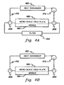
- FIGS. 4A & 5A depict alternate assemblies for filtering conditioned coolant within the thermal dissipation unit, for example, during fabrication of the unit.
- the system subassembly 195 of FIG. 3 is shown associated with an electronics module 190, which may be integrated with or coupled to the micro-scaled cooling structure 180.
- the subassembly includes two three-way valves 200, which are opened in this example to allow coolant flow through a filter 210 rather than through the micro-scaled cooling structure 180.
- the conditioned coolant pumped 175 through the heat exchanger, the third cooling loop 170 and filter 210 via the three-way valves 200, is purified to a desired level for a particular application.
- filter 210 can be any filtering mechanism designed to cleanse the conditioned coolant flowing through the third cooling loop 170 in a desired manner, and may include particulate filtering (resulting, e.g., from the manufacturing and assembly process), as well as chemical filtering (e.g., to remove undesired corrosive components from the coolant).
- valves 200 are either manually or automatically adjusted to remove filter 210 from the third cooling loop 170, thereby allowing the conditioned coolant to flow through the micro-scaled cooling structure 180 and heat exchanger 160 by means of pump 175 (see FIG. 4B ).
- FIG. 5A depicts an alternate method for filtering conditioned coolant within loop 170 of the cooling subassembly 195 of FIG. 3 .
- connect/disconnect couplings 220 are employed to connect a filter 210 to the third cooling loop 170.
- Filter 210 can again comprise any filtering mechanism for removing, for example, undesirable particulate and chemical components from the conditioned coolant flowing through the third cooling loop 170.
- Coolant is pumped 175 through the heat exchanger 160, the third cooling loop 170 and filter 210 for a sufficient period of time to achieve the desired level of coolant purity.
- filter 210 is removed and the micro-scaled cooling structure 180 is inserted into the third cooling loop, again using the couplings 220.
- an electronic module 190 is assumed to be integrated with or coupled to the micro-scaled cooling structure 180.
- FIGS. 6A-6C Various embodiments for coupling structure 180 to an electronic module are depicted in FIGS. 6A-6C and discussed further below.
- a cooling assembly which employs three distinct cooling loops.
- a first cooling loop and a second cooling loop are associated with a coolant distribution unit which includes a fluid-to-fluid heat exchanger to allow the transfer of heat from system coolant within the second cooling loop to facility coolant within the first cooling loop.
- One or more thermal dissipation units or cooling subassemblies are associated with one or more electronics subsystems of, for example, an electronics rack.
- Each thermal dissipation unit includes a respective second cooling loop and a third cooling loop, which in one example, comprises an isolated, closed loop flow path.
- the thermal dissipation unit further includes a second fluid-to-fluid heat exchanger which allows heat to be expelled from conditioned coolant within the third cooling loop to the system coolant within the second cooling loop for transfer to the coolant distribution unit.
- a second fluid-to-fluid heat exchanger which allows heat to be expelled from conditioned coolant within the third cooling loop to the system coolant within the second cooling loop for transfer to the coolant distribution unit.
- FIGS. 6A-6C depict various embodiments for coupling a micro-scaled cooling structure 180 to one or more heat generating components of an electronics subsystem.
- an electronic module 190 includes a substrate 191 having multiple integrated circuit chips 192 disposed thereon.
- a module lid 193 encases the integrated circuit chips within the module 190.
- Module 190 is shown mechanically coupled to a micro-scaled cooling structure 180 through which conditioned coolant (not shown) flows via an inlet 181 and outlet 184.
- Module lid 193 and micro-scaled cooling structure 180 are fabricated of materials appropriate for facilitating thermal transfer from integrated circuit chips 192 to the conditioned coolant flowing through the micro-scaled structure.
- the micro-scaled cooling structure 180 may be part of a thermal dissipation unit which is a field replaceable unit.
- connect/disconnect couplings may be employed in the second cooling loop to couple the system coolant to the newly replaced thermal dissipation unit without requiring opening of the third cooling loop containing the conditioned coolant flowing through the micro-scaled cooling structure 180.
- FIG. 6B depicts an alternate embodiment of a micro-scaled cooling structure coupled to a chip assembly, which is referred to herein as near-direct coolant immersion.
- cooling structure 180' couples to a substrate 191 having multiple integrated circuit chips 192 thereon.
- a multi-layer impermeable barrier 194 resides over the integrated circuit chips and protects the chips from the conditioned coolant flowing through the micro-scaled cooling structure 180'.
- Conditioned coolant flows onto the impermeable barrier 194 via micro-scaled orifices 183 in fluid communication with a supply manifold 182 receiving conditioned coolant via an inlet 181.
- Conditioned coolant flows from the integrated assembly via an outlet 184 in the micro-scaled cooling structure 180'.
- any type of coolant may be employed, with water being one example.
- liquid is in near-direct contact with the integrated circuit chips, but remains isolated therefrom.
- near-direct integrated cooling structure and module assemblies are described in greater detail in commonly assigned United States Patent No. US 6,587,345 entitled “Electronic Device Substrate Assembly With Impermeable Barrier And Method Of Making” and United States Patent Application No. 2004/0012914 A1 , entitled “Electronic Device Substrate Assembly With Multilayer Impermeable Barrier And Method Of Making", both of which are hereby incorporated herein by reference in their entirety.
- FIG. 6C depicts still another attachment embodiment for integrating a micro-scaled cooling structure with an integrated circuit assembly.
- This embodiment is referred to as direct coolant immersion since the conditioned coolant impinges directly onto the multiple integrated circuit chips 192 disposed on substrate 191.
- the micro-scaled cooling structure 180' again includes micro-scale orifices 183 which provide conditioned coolant from a supply manifold 182 in fluid communication with an inlet 181 coupled to the third cooling loop of the respective thermal dissipation unit.
- the micro-scaled cooling structure 180' in FIG. 6C includes an outlet 184, which is in fluid communication with the third cooling loop 170 of the thermal dissipation unit 195 of, for example, FIG. 3 .
Landscapes
- Engineering & Computer Science (AREA)
- Physics & Mathematics (AREA)
- Computer Hardware Design (AREA)
- Microelectronics & Electronic Packaging (AREA)
- Condensed Matter Physics & Semiconductors (AREA)
- General Physics & Mathematics (AREA)
- Power Engineering (AREA)
- General Engineering & Computer Science (AREA)
- Thermal Sciences (AREA)
- Cooling Or The Like Of Electrical Apparatus (AREA)
- Cooling Or The Like Of Semiconductors Or Solid State Devices (AREA)
- Motor Or Generator Cooling System (AREA)
Applications Claiming Priority (2)
| Application Number | Priority Date | Filing Date | Title |
|---|---|---|---|
| US11/008,711 US6973801B1 (en) | 2004-12-09 | 2004-12-09 | Cooling system and method employing a closed loop coolant path and micro-scaled cooling structure within an electronics subsystem of an electronics rack |
| PCT/EP2005/056581 WO2006061404A1 (en) | 2004-12-09 | 2005-12-07 | Cooling system and method |
Publications (2)
| Publication Number | Publication Date |
|---|---|
| EP1829441A1 EP1829441A1 (en) | 2007-09-05 |
| EP1829441B1 true EP1829441B1 (en) | 2008-04-02 |
Family
ID=35452409
Family Applications (1)
| Application Number | Title | Priority Date | Filing Date |
|---|---|---|---|
| EP05817223A Expired - Lifetime EP1829441B1 (en) | 2004-12-09 | 2005-12-07 | Cooling system and method |
Country Status (7)
| Country | Link |
|---|---|
| US (1) | US6973801B1 (enExample) |
| EP (1) | EP1829441B1 (enExample) |
| JP (1) | JP4511601B2 (enExample) |
| CN (1) | CN100556260C (enExample) |
| AT (1) | ATE391406T1 (enExample) |
| DE (1) | DE602005005859T2 (enExample) |
| WO (1) | WO2006061404A1 (enExample) |
Cited By (1)
| Publication number | Priority date | Publication date | Assignee | Title |
|---|---|---|---|---|
| EP4385294A4 (en) * | 2021-08-13 | 2025-09-10 | Jetcool Tech Inc | HOT-SPOT TARGETING AND CIRCULATING IMMERSION COOLING ASSEMBLY |
Families Citing this family (122)
| Publication number | Priority date | Publication date | Assignee | Title |
|---|---|---|---|---|
| US7836597B2 (en) | 2002-11-01 | 2010-11-23 | Cooligy Inc. | Method of fabricating high surface to volume ratio structures and their integration in microheat exchangers for liquid cooling system |
| US8464781B2 (en) | 2002-11-01 | 2013-06-18 | Cooligy Inc. | Cooling systems incorporating heat exchangers and thermoelectric layers |
| US7508672B2 (en) * | 2003-09-10 | 2009-03-24 | Qnx Cooling Systems Inc. | Cooling system |
| JP4468379B2 (ja) * | 2004-11-29 | 2010-05-26 | 三菱重工業株式会社 | 空気冷媒式冷凍加熱装置 |
| US8424885B2 (en) | 2005-12-22 | 2013-04-23 | Elliptical Mobile Solutions, LLC | Method and apparatus for an environmentally-protected electronic equipment enclosure |
| US7578337B2 (en) * | 2005-04-14 | 2009-08-25 | United States Thermoelectric Consortium | Heat dissipating device |
| US7298618B2 (en) * | 2005-10-25 | 2007-11-20 | International Business Machines Corporation | Cooling apparatuses and methods employing discrete cold plates compliantly coupled between a common manifold and electronics components of an assembly to be cooled |
| US7298617B2 (en) * | 2005-10-25 | 2007-11-20 | International Business Machines Corporation | Cooling apparatus and method employing discrete cold plates disposed between a module enclosure and electronics components to be cooled |
| US7992625B1 (en) | 2006-08-18 | 2011-08-09 | United States Thermoelectric Consortium | Fluid-operated heat transfer device |
| US7814965B1 (en) | 2005-10-27 | 2010-10-19 | United States Thermoelectric Consortium | Airflow heat dissipation device |
| US7365973B2 (en) | 2006-01-19 | 2008-04-29 | American Power Conversion Corporation | Cooling system and method |
| US8672732B2 (en) | 2006-01-19 | 2014-03-18 | Schneider Electric It Corporation | Cooling system and method |
| TW200810676A (en) * | 2006-03-30 | 2008-02-16 | Cooligy Inc | Multi device cooling |
| CA2653806C (en) | 2006-06-01 | 2014-06-03 | Exaflop Llc | Warm cooling for electronics |
| US9568206B2 (en) | 2006-08-15 | 2017-02-14 | Schneider Electric It Corporation | Method and apparatus for cooling |
| US8322155B2 (en) | 2006-08-15 | 2012-12-04 | American Power Conversion Corporation | Method and apparatus for cooling |
| US8327656B2 (en) | 2006-08-15 | 2012-12-11 | American Power Conversion Corporation | Method and apparatus for cooling |
| US20080043442A1 (en) * | 2006-08-16 | 2008-02-21 | Strickland Travis C | Computer system with thermal conduction |
| US7665325B2 (en) * | 2006-09-12 | 2010-02-23 | International Business Machines Corporation | Multi-fluid cooling system and method with freeze protection for cooling an electronic device |
| US7681404B2 (en) | 2006-12-18 | 2010-03-23 | American Power Conversion Corporation | Modular ice storage for uninterruptible chilled water |
| US8425287B2 (en) | 2007-01-23 | 2013-04-23 | Schneider Electric It Corporation | In-row air containment and cooling system and method |
| US8141620B1 (en) | 2007-02-26 | 2012-03-27 | United States Thermoelectric Consortium (USTC) | Method for conditioning a cooling loop of a heat exchange system |
| US7511959B2 (en) * | 2007-04-25 | 2009-03-31 | Hewlett-Packard Development Company, L.P. | Scalable computing apparatus |
| US7477514B2 (en) * | 2007-05-04 | 2009-01-13 | International Business Machines Corporation | Method of facilitating cooling of electronics racks of a data center employing multiple cooling stations |
| EP2147585B1 (en) | 2007-05-15 | 2016-11-02 | Schneider Electric IT Corporation | Method and system for managing facility power and cooling |
| US7602609B2 (en) * | 2007-05-31 | 2009-10-13 | Liebert Corporation | Cooling system and method of use |
| TW200912621A (en) * | 2007-08-07 | 2009-03-16 | Cooligy Inc | Method and apparatus for providing a supplemental cooling to server racks |
| US9943014B2 (en) | 2013-03-15 | 2018-04-10 | Coolit Systems, Inc. | Manifolded heat exchangers and related systems |
| US9453691B2 (en) | 2007-08-09 | 2016-09-27 | Coolit Systems, Inc. | Fluid heat exchange systems |
| US9496200B2 (en) | 2011-07-27 | 2016-11-15 | Coolit Systems, Inc. | Modular heat-transfer systems |
| US8746330B2 (en) | 2007-08-09 | 2014-06-10 | Coolit Systems Inc. | Fluid heat exchanger configured to provide a split flow |
| US20090229283A1 (en) * | 2007-08-24 | 2009-09-17 | Joseph Marsala | Method and apparatus for isothermal cooling of hard disk drive arrays using a pumped refrigerant loop |
| US7963119B2 (en) * | 2007-11-26 | 2011-06-21 | International Business Machines Corporation | Hybrid air and liquid coolant conditioning unit for facilitating cooling of one or more electronics racks of a data center |
| US8553416B1 (en) | 2007-12-21 | 2013-10-08 | Exaflop Llc | Electronic device cooling system with storage |
| CA2882794C (en) * | 2008-02-15 | 2017-08-22 | The Pnc Financial Services Group, Inc. | Systems and methods for computer equipment management |
| US20090225514A1 (en) | 2008-03-10 | 2009-09-10 | Adrian Correa | Device and methodology for the removal of heat from an equipment rack by means of heat exchangers mounted to a door |
| US8299604B2 (en) | 2008-08-05 | 2012-10-30 | Cooligy Inc. | Bonded metal and ceramic plates for thermal management of optical and electronic devices |
| US20100085708A1 (en) * | 2008-10-07 | 2010-04-08 | Liebert Corporation | High-efficiency, fluid-cooled ups converter |
| US7916483B2 (en) | 2008-10-23 | 2011-03-29 | International Business Machines Corporation | Open flow cold plate for liquid cooled electronic packages |
| US7885070B2 (en) * | 2008-10-23 | 2011-02-08 | International Business Machines Corporation | Apparatus and method for immersion-cooling of an electronic system utilizing coolant jet impingement and coolant wash flow |
| US7944694B2 (en) | 2008-10-23 | 2011-05-17 | International Business Machines Corporation | Liquid cooling apparatus and method for cooling blades of an electronic system chassis |
| US7983040B2 (en) | 2008-10-23 | 2011-07-19 | International Business Machines Corporation | Apparatus and method for facilitating pumped immersion-cooling of an electronic subsystem |
| US7961475B2 (en) | 2008-10-23 | 2011-06-14 | International Business Machines Corporation | Apparatus and method for facilitating immersion-cooling of an electronic subsystem |
| US7903404B2 (en) * | 2009-04-29 | 2011-03-08 | Hewlett-Packard Development Company, L.P. | Data centers |
| US8219362B2 (en) | 2009-05-08 | 2012-07-10 | American Power Conversion Corporation | System and method for arranging equipment in a data center |
| US8369090B2 (en) | 2009-05-12 | 2013-02-05 | Iceotope Limited | Cooled electronic system |
| CN105491858B (zh) * | 2009-05-12 | 2018-12-18 | 爱思欧托普有限公司 | 被冷却的电子系统 |
| US8081461B2 (en) * | 2009-06-25 | 2011-12-20 | International Business Machines Corporation | Cooling apparatus with thermally conductive porous material and jet impingement nozzle(s) extending therein |
| US8490419B2 (en) * | 2009-08-20 | 2013-07-23 | United States Thermoelectric Consortium | Interlocked jets cooling method and apparatus |
| US8522569B2 (en) | 2009-10-27 | 2013-09-03 | Industrial Idea Partners, Inc. | Utilization of data center waste heat for heat driven engine |
| US8189334B2 (en) | 2010-05-26 | 2012-05-29 | International Business Machines Corporation | Dehumidifying and re-humidifying cooling apparatus and method for an electronics rack |
| US9038406B2 (en) | 2010-05-26 | 2015-05-26 | International Business Machines Corporation | Dehumidifying cooling apparatus and method for an electronics rack |
| US7905096B1 (en) * | 2010-05-26 | 2011-03-15 | International Business Machines Corporation | Dehumidifying and re-humidifying air cooling for an electronics rack |
| US8144467B2 (en) | 2010-05-26 | 2012-03-27 | International Business Machines Corporation | Dehumidifying and re-humidifying apparatus and method for an electronics rack |
| US8345423B2 (en) | 2010-06-29 | 2013-01-01 | International Business Machines Corporation | Interleaved, immersion-cooling apparatuses and methods for cooling electronic subsystems |
| US8369091B2 (en) | 2010-06-29 | 2013-02-05 | International Business Machines Corporation | Interleaved, immersion-cooling apparatus and method for an electronic subsystem of an electronics rack |
| US8184436B2 (en) | 2010-06-29 | 2012-05-22 | International Business Machines Corporation | Liquid-cooled electronics rack with immersion-cooled electronic subsystems |
| US8179677B2 (en) | 2010-06-29 | 2012-05-15 | International Business Machines Corporation | Immersion-cooling apparatus and method for an electronic subsystem of an electronics rack |
| US8351206B2 (en) | 2010-06-29 | 2013-01-08 | International Business Machines Corporation | Liquid-cooled electronics rack with immersion-cooled electronic subsystems and vertically-mounted, vapor-condensing unit |
| US8514575B2 (en) | 2010-11-16 | 2013-08-20 | International Business Machines Corporation | Multimodal cooling apparatus for an electronic system |
| US8274790B2 (en) | 2010-11-16 | 2012-09-25 | International Business Machines Corporation | Automatically reconfigurable liquid-cooling apparatus for an electronics rack |
| US8688413B2 (en) | 2010-12-30 | 2014-04-01 | Christopher M. Healey | System and method for sequential placement of cooling resources within data center layouts |
| WO2014141162A1 (en) | 2013-03-15 | 2014-09-18 | Coolit Systems, Inc. | Sensors, multiplexed communication techniques, and related systems |
| US10365667B2 (en) | 2011-08-11 | 2019-07-30 | Coolit Systems, Inc. | Flow-path controllers and related systems |
| US8760863B2 (en) | 2011-10-31 | 2014-06-24 | International Business Machines Corporation | Multi-rack assembly with shared cooling apparatus |
| US8817474B2 (en) | 2011-10-31 | 2014-08-26 | International Business Machines Corporation | Multi-rack assembly with shared cooling unit |
| US20130112378A1 (en) * | 2011-11-04 | 2013-05-09 | Dell Products L.P. | System and Method for Cooling Information Handling Resources |
| EP2795489A4 (en) | 2011-12-22 | 2016-06-01 | Schneider Electric It Corp | ANALYSIS OF THE IMPACT OF TRANSITION EVENTS ON THE TEMPERATURE IN A DATA CENTER |
| AU2011383606A1 (en) | 2011-12-22 | 2014-07-17 | Schneider Electric It Corporation | System and method for prediction of temperature values in an electronics system |
| US9167728B2 (en) * | 2012-07-18 | 2015-10-20 | International Business Machines Corporation | Information technology equipment cooling method |
| US8964384B2 (en) * | 2012-07-27 | 2015-02-24 | Hewlett-Packard Development Company, L.P. | Component cooling |
| US20140048993A1 (en) * | 2012-08-17 | 2014-02-20 | Apple Inc. | Selective placement of coolant to undercut areas |
| US8925333B2 (en) | 2012-09-13 | 2015-01-06 | International Business Machines Corporation | Thermoelectric-enhanced air and liquid cooling of an electronic system |
| US9351431B2 (en) | 2012-10-11 | 2016-05-24 | International Business Machines Corporation | Cooling system with automated seasonal freeze protection |
| US12366870B2 (en) | 2013-03-15 | 2025-07-22 | Coolit Systems, Inc. | Flow-path controllers and related systems |
| US9648784B2 (en) | 2013-03-15 | 2017-05-09 | Inertech Ip Llc | Systems and assemblies for cooling server racks |
| US9713285B2 (en) | 2013-03-29 | 2017-07-18 | Hewlett Packard Enterprise Development Lp | Electronic apparatus having a cooling apparatus |
| TW201515563A (zh) * | 2013-10-08 | 2015-04-16 | Hon Hai Prec Ind Co Ltd | 散熱系統 |
| US10197310B2 (en) | 2014-06-20 | 2019-02-05 | Nortek Air Solutions Canada, Inc. | Systems and methods for managing conditions in enclosed space |
| US10168061B2 (en) * | 2014-11-11 | 2019-01-01 | Emerson Network Power S.R.L. | Conditioning system of the free cooling type for environments, method of operation of a said conditioning system, and apparatus for carrying out such method |
| WO2016076882A1 (en) | 2014-11-14 | 2016-05-19 | Hewlett Packard Enterprise Development Lp | Cooling rack |
| US11092349B2 (en) | 2015-05-15 | 2021-08-17 | Nortek Air Solutions Canada, Inc. | Systems and methods for providing cooling to a heat load |
| EP3985322B1 (en) | 2015-05-15 | 2024-11-06 | Nortek Air Solutions Canada, Inc. | Air conditioning system with a liquid to air membrane energy exchanger |
| US11026351B2 (en) * | 2015-09-25 | 2021-06-01 | Intel Corporation | Computing apparatus with closed cooling loop |
| US10834855B2 (en) | 2016-01-08 | 2020-11-10 | Nortek Air Solutions Canada, Inc. | Integrated make-up air system in 100% air recirculation system |
| EP3430327A1 (en) | 2016-03-16 | 2019-01-23 | Inertech IP LLC | System and methods utilizing fluid coolers and chillers to perform in-series heat rejection and trim cooling |
| US10049963B2 (en) * | 2016-04-18 | 2018-08-14 | Rolls-Royce Plc | Power electronics module |
| JP6907592B2 (ja) | 2017-02-28 | 2021-07-21 | 富士通株式会社 | 冷却装置及び電子機器システム |
| US11452243B2 (en) | 2017-10-12 | 2022-09-20 | Coolit Systems, Inc. | Cooling system, controllers and methods |
| DE202018102582U1 (de) | 2018-01-23 | 2018-05-22 | MEGWARE Computer Vertrieb und Service GmbH | Hochtemperatur-direktflüssigkeitsgekühltes Hochleistungsrechnersystem |
| US10681846B2 (en) | 2018-04-19 | 2020-06-09 | Google Llc | Cooling electronic devices in a data center |
| US10645847B2 (en) | 2018-04-20 | 2020-05-05 | Google Llc | Cooling electronic devices in a data center |
| US10966352B2 (en) | 2018-09-24 | 2021-03-30 | Google Llc | Cooling electronic devices in a data center |
| US10548239B1 (en) * | 2018-10-23 | 2020-01-28 | Google Llc | Cooling electronic devices in a data center |
| GB201916771D0 (en) | 2019-11-18 | 2020-01-01 | Iceotope Group Ltd | Heat sink for liquid cooling |
| US10548240B1 (en) | 2019-01-11 | 2020-01-28 | Google Llc | Cooling electronic devices in a data center |
| US11662037B2 (en) | 2019-01-18 | 2023-05-30 | Coolit Systems, Inc. | Fluid flow control valve for fluid flow systems, and methods |
| WO2020210587A1 (en) | 2019-04-10 | 2020-10-15 | Jetcool Technologies, Inc. | Thermal management of electronics using co-located microjet nozzles and electronic elements |
| EP3977832B1 (en) | 2019-04-14 | 2025-06-04 | Jetcool Technologies, Inc. | Direct contact fluid based cooling module |
| US11473860B2 (en) | 2019-04-25 | 2022-10-18 | Coolit Systems, Inc. | Cooling module with leak detector and related systems |
| WO2020257923A1 (en) * | 2019-06-27 | 2020-12-30 | Hypertechnologie Ciara Inc. | Microgap system for cooling electronics with direct contact |
| US11801733B2 (en) | 2019-09-25 | 2023-10-31 | Baidu Usa Llc | Liquid cooling loop design for high performance processors in harsh vehicle environment |
| GB201916763D0 (en) * | 2019-11-18 | 2020-01-01 | Iceotope Group Ltd | Nozzle arrangement and cooling module |
| US10959352B1 (en) * | 2020-01-03 | 2021-03-23 | Quanta Computer Inc. | Cooling system with floating cold plate with single pipes |
| US11212943B2 (en) | 2020-02-21 | 2021-12-28 | Nvidia Corporation | Universal pluggable datacenter cooling system |
| WO2021229365A1 (en) | 2020-05-11 | 2021-11-18 | Coolit Systems, Inc. | Liquid pumping units, and related systems and methods |
| WO2022060898A1 (en) | 2020-09-15 | 2022-03-24 | Jetcool Technologies Inc. | High temperature electronic device thermal management system |
| US12289871B2 (en) | 2020-09-15 | 2025-04-29 | Jetcool Technologies Inc. | High temperature electronic device thermal management system |
| US11211538B1 (en) | 2020-12-23 | 2021-12-28 | Joseph L. Pikulski | Thermal management system for electrically-powered devices |
| US11950396B2 (en) * | 2020-12-30 | 2024-04-02 | Nvidia Corporation | Intelligent swappable modular unit for local cooling loops in a datacenter cooling system |
| TW202236557A (zh) | 2021-01-20 | 2022-09-16 | 美商捷控技術有限公司 | 用於多晶電子組件之基板防流體的順應性冷卻組件 |
| US11903166B2 (en) * | 2021-02-01 | 2024-02-13 | Microsoft Technology Licensing, Llc | Systems and methods for immersion cooling with subcooled spray |
| US12082382B2 (en) * | 2021-04-23 | 2024-09-03 | Nvidia Corporation | Intelligent in-rack pump or compressor unit for datacenter cooling systems |
| US11812589B2 (en) * | 2021-05-12 | 2023-11-07 | Nvidia Corporation | Intelligent refrigerant distribution unit for datacenter cooling systems |
| US11725886B2 (en) | 2021-05-20 | 2023-08-15 | Coolit Systems, Inc. | Modular fluid heat exchange systems |
| US11627687B2 (en) * | 2021-06-22 | 2023-04-11 | Baidu Usa Llc | Multiple phase multiple system architecture |
| US20230142683A1 (en) | 2021-11-09 | 2023-05-11 | Hoffman Enclosures Inc. | Coolant Distribution Unit and Control System |
| US12289861B2 (en) | 2021-11-12 | 2025-04-29 | Jetcool Technologies Inc. | Liquid-in-liquid cooling system for electronic components |
| US20230180436A1 (en) * | 2021-12-08 | 2023-06-08 | Treis Blockchain, Llc | System for cooling electrical components and recycling heat |
| US12200914B2 (en) | 2022-01-24 | 2025-01-14 | Coolit Systems, Inc. | Smart components, systems and methods for transferring heat |
| TW202407925A (zh) | 2022-03-04 | 2024-02-16 | 美商捷控技術有限公司 | 用於電腦處理器及處理器組件之主動冷卻散熱蓋 |
| US12369282B2 (en) | 2023-07-26 | 2025-07-22 | Quanta Computer Inc. | Liquid cooling rack assembly for computing system and telecommunication system including the same |
Family Cites Families (22)
| Publication number | Priority date | Publication date | Assignee | Title |
|---|---|---|---|---|
| DE3032590A1 (de) * | 1980-08-27 | 1982-04-01 | Siemens AG, 1000 Berlin und 8000 München | Anordnung zur kuehlung einer gas- oder fluessigkeitsgekuehlten elektrischen maschine |
| JPS62119620A (ja) * | 1985-11-20 | 1987-05-30 | Fujitsu Ltd | 冷却水供給装置 |
| US5131233A (en) | 1991-03-08 | 1992-07-21 | Cray Computer Corporation | Gas-liquid forced turbulence cooling |
| SE505272C2 (sv) * | 1994-12-14 | 1997-07-28 | Ericsson Telefon Ab L M | Kylsystem för telekommunikationsutrustning |
| JP2874684B2 (ja) * | 1997-03-27 | 1999-03-24 | 日本電気株式会社 | プラグインユニットの放熱構造 |
| US5924482A (en) | 1997-10-29 | 1999-07-20 | Motorola, Inc. | Multi-mode, two-phase cooling module |
| US6019165A (en) | 1998-05-18 | 2000-02-01 | Batchelder; John Samuel | Heat exchange apparatus |
| US20020134544A1 (en) * | 2000-09-07 | 2002-09-26 | Thermotek, Inc. | Passive cooling system and method |
| US6408937B1 (en) | 2000-11-15 | 2002-06-25 | Sanjay K. Roy | Active cold plate/heat sink |
| US7225864B2 (en) * | 2001-02-08 | 2007-06-05 | Oriol Inc. | Multi-channel temperature control system for semiconductor processing facilities |
| US6604370B2 (en) | 2001-02-22 | 2003-08-12 | Hewlett-Packard Development Company, L.P. | Variably configured sprayjet cooling system |
| US6498725B2 (en) | 2001-05-01 | 2002-12-24 | Mainstream Engineering Corporation | Method and two-phase spray cooling apparatus |
| TW561226B (en) | 2001-09-25 | 2003-11-11 | Matsushita Electric Industrial Co Ltd | Ultra-thin pump and cooling system including the pump |
| US6587345B2 (en) | 2001-11-09 | 2003-07-01 | International Business Machines Corporation | Electronic device substrate assembly with impermeable barrier and method of making |
| US6628520B2 (en) * | 2002-02-06 | 2003-09-30 | Hewlett-Packard Development Company, L.P. | Method, apparatus, and system for cooling electronic components |
| US6625023B1 (en) | 2002-04-11 | 2003-09-23 | General Dynamics Land Systems, Inc. | Modular spray cooling system for electronic components |
| US6604571B1 (en) | 2002-04-11 | 2003-08-12 | General Dynamics Land Systems, Inc. | Evaporative cooling of electrical components |
| US6940712B2 (en) | 2002-07-17 | 2005-09-06 | International Business Machines Corporation | Electronic device substrate assembly with multilayer impermeable barrier and method of making |
| US6807056B2 (en) * | 2002-09-24 | 2004-10-19 | Hitachi, Ltd. | Electronic equipment |
| US7146822B2 (en) | 2002-12-30 | 2006-12-12 | Intel Corporation | Centrifugal liquid pump with perimeter magnetic drive |
| US7106590B2 (en) * | 2003-12-03 | 2006-09-12 | International Business Machines Corporation | Cooling system and method employing multiple dedicated coolant conditioning units for cooling multiple electronics subsystems |
| CN100338983C (zh) * | 2003-12-03 | 2007-09-19 | 国际商业机器公司 | 确保冷却多个电子设备子系统的冷却系统和方法 |
-
2004
- 2004-12-09 US US11/008,711 patent/US6973801B1/en not_active Expired - Lifetime
-
2005
- 2005-12-07 WO PCT/EP2005/056581 patent/WO2006061404A1/en not_active Ceased
- 2005-12-07 JP JP2007544912A patent/JP4511601B2/ja not_active Expired - Lifetime
- 2005-12-07 DE DE602005005859T patent/DE602005005859T2/de not_active Expired - Lifetime
- 2005-12-07 AT AT05817223T patent/ATE391406T1/de not_active IP Right Cessation
- 2005-12-07 CN CN200580042255.3A patent/CN100556260C/zh not_active Expired - Lifetime
- 2005-12-07 EP EP05817223A patent/EP1829441B1/en not_active Expired - Lifetime
Cited By (1)
| Publication number | Priority date | Publication date | Assignee | Title |
|---|---|---|---|---|
| EP4385294A4 (en) * | 2021-08-13 | 2025-09-10 | Jetcool Tech Inc | HOT-SPOT TARGETING AND CIRCULATING IMMERSION COOLING ASSEMBLY |
Also Published As
| Publication number | Publication date |
|---|---|
| DE602005005859T2 (de) | 2009-05-20 |
| CN101091424A (zh) | 2007-12-19 |
| EP1829441A1 (en) | 2007-09-05 |
| DE602005005859D1 (de) | 2008-05-15 |
| US6973801B1 (en) | 2005-12-13 |
| CN100556260C (zh) | 2009-10-28 |
| JP2008523599A (ja) | 2008-07-03 |
| ATE391406T1 (de) | 2008-04-15 |
| WO2006061404A1 (en) | 2006-06-15 |
| JP4511601B2 (ja) | 2010-07-28 |
Similar Documents
| Publication | Publication Date | Title |
|---|---|---|
| EP1829441B1 (en) | Cooling system and method | |
| US7272005B2 (en) | Multi-element heat exchange assemblies and methods of fabrication for a cooling system | |
| US7274566B2 (en) | Cooling apparatus for an electronics subsystem employing a coolant flow drive apparatus between coolant flow paths | |
| US7184269B2 (en) | Cooling apparatus and method for an electronics module employing an integrated heat exchange assembly | |
| US7298618B2 (en) | Cooling apparatuses and methods employing discrete cold plates compliantly coupled between a common manifold and electronics components of an assembly to be cooled | |
| US10070560B2 (en) | Drawer-level immersion-cooling with hinged, liquid-cooled heat sink | |
| US9253921B2 (en) | Coolant-conditioning unit with automated control of coolant flow valves | |
| US9743561B2 (en) | Liquid-cooled heat sink configured to facilitate drainage | |
| CN102342192B (zh) | 液冷式冷却装置、电子机架及其制造方法 | |
| US7673389B2 (en) | Cold plate apparatus and method of fabrication thereof with a controlled heat transfer characteristic between a metallurgically bonded tube and heat sink for facilitating cooling of an electronics component | |
| US9282678B2 (en) | Field-replaceable bank of immersion-cooled electronic components and separable heat sinks | |
| US8724322B2 (en) | Targeted liquid cooling for a system |
Legal Events
| Date | Code | Title | Description |
|---|---|---|---|
| PUAI | Public reference made under article 153(3) epc to a published international application that has entered the european phase |
Free format text: ORIGINAL CODE: 0009012 |
|
| 17P | Request for examination filed |
Effective date: 20070704 |
|
| AK | Designated contracting states |
Kind code of ref document: A1 Designated state(s): AT BE BG CH CY CZ DE DK EE ES FI FR GB GR HU IE IS IT LI LT LU LV MC NL PL PT RO SE SI SK TR |
|
| RIN1 | Information on inventor provided before grant (corrected) |
Inventor name: IYENGAR, MADHUSUDAN C/O IBM UK LIMITED IPL Inventor name: CHU, RICHARD Inventor name: SIMONS, ROBERT Inventor name: SCHMIDT, ROGER Inventor name: CAMPBELL, LEVI Inventor name: ELLSWORTH, MICHAEL |
|
| GRAP | Despatch of communication of intention to grant a patent |
Free format text: ORIGINAL CODE: EPIDOSNIGR1 |
|
| DAX | Request for extension of the european patent (deleted) | ||
| RIN1 | Information on inventor provided before grant (corrected) |
Inventor name: ELLSWORTH, MICHAEL Inventor name: CAMPBELL, LEVI Inventor name: SIMONS, ROBERT Inventor name: IYENGAR, MADHUSUDANC/O IBM UK LIMITED IPL Inventor name: SCHMIDT, ROGER Inventor name: CHU, RICHARD |
|
| GRAS | Grant fee paid |
Free format text: ORIGINAL CODE: EPIDOSNIGR3 |
|
| GRAA | (expected) grant |
Free format text: ORIGINAL CODE: 0009210 |
|
| AK | Designated contracting states |
Kind code of ref document: B1 Designated state(s): AT BE BG CH CY CZ DE DK EE ES FI FR GB GR HU IE IS IT LI LT LU LV MC NL PL PT RO SE SI SK TR |
|
| REG | Reference to a national code |
Ref country code: GB Ref legal event code: FG4D |
|
| REG | Reference to a national code |
Ref country code: CH Ref legal event code: EP Ref country code: IE Ref legal event code: FG4D |
|
| REF | Corresponds to: |
Ref document number: 602005005859 Country of ref document: DE Date of ref document: 20080515 Kind code of ref document: P |
|
| REG | Reference to a national code |
Ref country code: GB Ref legal event code: 746 Effective date: 20080506 |
|
| PG25 | Lapsed in a contracting state [announced via postgrant information from national office to epo] |
Ref country code: SI Free format text: LAPSE BECAUSE OF FAILURE TO SUBMIT A TRANSLATION OF THE DESCRIPTION OR TO PAY THE FEE WITHIN THE PRESCRIBED TIME-LIMIT Effective date: 20080402 |
|
| NLV1 | Nl: lapsed or annulled due to failure to fulfill the requirements of art. 29p and 29m of the patents act | ||
| PG25 | Lapsed in a contracting state [announced via postgrant information from national office to epo] |
Ref country code: PT Free format text: LAPSE BECAUSE OF FAILURE TO SUBMIT A TRANSLATION OF THE DESCRIPTION OR TO PAY THE FEE WITHIN THE PRESCRIBED TIME-LIMIT Effective date: 20080904 Ref country code: BG Free format text: LAPSE BECAUSE OF FAILURE TO SUBMIT A TRANSLATION OF THE DESCRIPTION OR TO PAY THE FEE WITHIN THE PRESCRIBED TIME-LIMIT Effective date: 20080702 Ref country code: ES Free format text: LAPSE BECAUSE OF FAILURE TO SUBMIT A TRANSLATION OF THE DESCRIPTION OR TO PAY THE FEE WITHIN THE PRESCRIBED TIME-LIMIT Effective date: 20080713 Ref country code: NL Free format text: LAPSE BECAUSE OF FAILURE TO SUBMIT A TRANSLATION OF THE DESCRIPTION OR TO PAY THE FEE WITHIN THE PRESCRIBED TIME-LIMIT Effective date: 20080402 Ref country code: FI Free format text: LAPSE BECAUSE OF FAILURE TO SUBMIT A TRANSLATION OF THE DESCRIPTION OR TO PAY THE FEE WITHIN THE PRESCRIBED TIME-LIMIT Effective date: 20080402 |
|
| PG25 | Lapsed in a contracting state [announced via postgrant information from national office to epo] |
Ref country code: PL Free format text: LAPSE BECAUSE OF FAILURE TO SUBMIT A TRANSLATION OF THE DESCRIPTION OR TO PAY THE FEE WITHIN THE PRESCRIBED TIME-LIMIT Effective date: 20080402 Ref country code: AT Free format text: LAPSE BECAUSE OF FAILURE TO SUBMIT A TRANSLATION OF THE DESCRIPTION OR TO PAY THE FEE WITHIN THE PRESCRIBED TIME-LIMIT Effective date: 20080402 Ref country code: LV Free format text: LAPSE BECAUSE OF FAILURE TO SUBMIT A TRANSLATION OF THE DESCRIPTION OR TO PAY THE FEE WITHIN THE PRESCRIBED TIME-LIMIT Effective date: 20080402 |
|
| ET | Fr: translation filed | ||
| PG25 | Lapsed in a contracting state [announced via postgrant information from national office to epo] |
Ref country code: IS Free format text: LAPSE BECAUSE OF FAILURE TO SUBMIT A TRANSLATION OF THE DESCRIPTION OR TO PAY THE FEE WITHIN THE PRESCRIBED TIME-LIMIT Effective date: 20080802 |
|
| PG25 | Lapsed in a contracting state [announced via postgrant information from national office to epo] |
Ref country code: SE Free format text: LAPSE BECAUSE OF FAILURE TO SUBMIT A TRANSLATION OF THE DESCRIPTION OR TO PAY THE FEE WITHIN THE PRESCRIBED TIME-LIMIT Effective date: 20080702 Ref country code: CZ Free format text: LAPSE BECAUSE OF FAILURE TO SUBMIT A TRANSLATION OF THE DESCRIPTION OR TO PAY THE FEE WITHIN THE PRESCRIBED TIME-LIMIT Effective date: 20080402 Ref country code: LT Free format text: LAPSE BECAUSE OF FAILURE TO SUBMIT A TRANSLATION OF THE DESCRIPTION OR TO PAY THE FEE WITHIN THE PRESCRIBED TIME-LIMIT Effective date: 20080402 Ref country code: DK Free format text: LAPSE BECAUSE OF FAILURE TO SUBMIT A TRANSLATION OF THE DESCRIPTION OR TO PAY THE FEE WITHIN THE PRESCRIBED TIME-LIMIT Effective date: 20080402 |
|
| PLBE | No opposition filed within time limit |
Free format text: ORIGINAL CODE: 0009261 |
|
| STAA | Information on the status of an ep patent application or granted ep patent |
Free format text: STATUS: NO OPPOSITION FILED WITHIN TIME LIMIT |
|
| PG25 | Lapsed in a contracting state [announced via postgrant information from national office to epo] |
Ref country code: RO Free format text: LAPSE BECAUSE OF FAILURE TO SUBMIT A TRANSLATION OF THE DESCRIPTION OR TO PAY THE FEE WITHIN THE PRESCRIBED TIME-LIMIT Effective date: 20080402 Ref country code: SK Free format text: LAPSE BECAUSE OF FAILURE TO SUBMIT A TRANSLATION OF THE DESCRIPTION OR TO PAY THE FEE WITHIN THE PRESCRIBED TIME-LIMIT Effective date: 20080402 Ref country code: BE Free format text: LAPSE BECAUSE OF FAILURE TO SUBMIT A TRANSLATION OF THE DESCRIPTION OR TO PAY THE FEE WITHIN THE PRESCRIBED TIME-LIMIT Effective date: 20080402 |
|
| 26N | No opposition filed |
Effective date: 20090106 |
|
| PG25 | Lapsed in a contracting state [announced via postgrant information from national office to epo] |
Ref country code: EE Free format text: LAPSE BECAUSE OF FAILURE TO SUBMIT A TRANSLATION OF THE DESCRIPTION OR TO PAY THE FEE WITHIN THE PRESCRIBED TIME-LIMIT Effective date: 20080402 |
|
| PG25 | Lapsed in a contracting state [announced via postgrant information from national office to epo] |
Ref country code: MC Free format text: LAPSE BECAUSE OF NON-PAYMENT OF DUE FEES Effective date: 20081231 |
|
| PG25 | Lapsed in a contracting state [announced via postgrant information from national office to epo] |
Ref country code: IT Free format text: LAPSE BECAUSE OF FAILURE TO SUBMIT A TRANSLATION OF THE DESCRIPTION OR TO PAY THE FEE WITHIN THE PRESCRIBED TIME-LIMIT Effective date: 20080402 |
|
| PG25 | Lapsed in a contracting state [announced via postgrant information from national office to epo] |
Ref country code: CY Free format text: LAPSE BECAUSE OF FAILURE TO SUBMIT A TRANSLATION OF THE DESCRIPTION OR TO PAY THE FEE WITHIN THE PRESCRIBED TIME-LIMIT Effective date: 20080402 |
|
| PG25 | Lapsed in a contracting state [announced via postgrant information from national office to epo] |
Ref country code: IE Free format text: LAPSE BECAUSE OF NON-PAYMENT OF DUE FEES Effective date: 20081208 |
|
| PG25 | Lapsed in a contracting state [announced via postgrant information from national office to epo] |
Ref country code: HU Free format text: LAPSE BECAUSE OF FAILURE TO SUBMIT A TRANSLATION OF THE DESCRIPTION OR TO PAY THE FEE WITHIN THE PRESCRIBED TIME-LIMIT Effective date: 20081003 Ref country code: LU Free format text: LAPSE BECAUSE OF NON-PAYMENT OF DUE FEES Effective date: 20081207 |
|
| REG | Reference to a national code |
Ref country code: CH Ref legal event code: PL |
|
| PG25 | Lapsed in a contracting state [announced via postgrant information from national office to epo] |
Ref country code: TR Free format text: LAPSE BECAUSE OF FAILURE TO SUBMIT A TRANSLATION OF THE DESCRIPTION OR TO PAY THE FEE WITHIN THE PRESCRIBED TIME-LIMIT Effective date: 20080402 |
|
| PG25 | Lapsed in a contracting state [announced via postgrant information from national office to epo] |
Ref country code: GR Free format text: LAPSE BECAUSE OF FAILURE TO SUBMIT A TRANSLATION OF THE DESCRIPTION OR TO PAY THE FEE WITHIN THE PRESCRIBED TIME-LIMIT Effective date: 20080703 Ref country code: LI Free format text: LAPSE BECAUSE OF NON-PAYMENT OF DUE FEES Effective date: 20091231 Ref country code: CH Free format text: LAPSE BECAUSE OF NON-PAYMENT OF DUE FEES Effective date: 20091231 |
|
| REG | Reference to a national code |
Ref country code: DE Ref legal event code: R082 Ref document number: 602005005859 Country of ref document: DE Representative=s name: DUSCHER, REINHARD, DIPL.-PHYS. DR.RER.NAT., DE Ref country code: DE Ref legal event code: R081 Ref document number: 602005005859 Country of ref document: DE Owner name: LENOVO INTERNATIONAL LIMITED, HK Free format text: FORMER OWNER: INTERNATIONAL BUSINESS MACHINES CORPORATION, ARMONK, N.Y., US |
|
| REG | Reference to a national code |
Ref country code: FR Ref legal event code: PLFP Year of fee payment: 11 |
|
| REG | Reference to a national code |
Ref country code: FR Ref legal event code: PLFP Year of fee payment: 12 |
|
| REG | Reference to a national code |
Ref country code: FR Ref legal event code: PLFP Year of fee payment: 13 |
|
| P01 | Opt-out of the competence of the unified patent court (upc) registered |
Effective date: 20230627 |
|
| PGFP | Annual fee paid to national office [announced via postgrant information from national office to epo] |
Ref country code: GB Payment date: 20241217 Year of fee payment: 20 |
|
| PGFP | Annual fee paid to national office [announced via postgrant information from national office to epo] |
Ref country code: FR Payment date: 20241227 Year of fee payment: 20 |
|
| PGFP | Annual fee paid to national office [announced via postgrant information from national office to epo] |
Ref country code: DE Payment date: 20241227 Year of fee payment: 20 |
|
| REG | Reference to a national code |
Ref country code: DE Ref legal event code: R071 Ref document number: 602005005859 Country of ref document: DE |