EP3977832B1 - Direct contact fluid based cooling module - Google Patents
Direct contact fluid based cooling module Download PDFInfo
- Publication number
- EP3977832B1 EP3977832B1 EP20791872.3A EP20791872A EP3977832B1 EP 3977832 B1 EP3977832 B1 EP 3977832B1 EP 20791872 A EP20791872 A EP 20791872A EP 3977832 B1 EP3977832 B1 EP 3977832B1
- Authority
- EP
- European Patent Office
- Prior art keywords
- fluid
- manifold
- direct
- cooling module
- based cooling
- Prior art date
- Legal status (The legal status is an assumption and is not a legal conclusion. Google has not performed a legal analysis and makes no representation as to the accuracy of the status listed.)
- Active
Links
Images


Classifications
-
- H—ELECTRICITY
- H01—ELECTRIC ELEMENTS
- H01L—SEMICONDUCTOR DEVICES NOT COVERED BY CLASS H10
- H01L23/00—Details of semiconductor or other solid state devices
- H01L23/34—Arrangements for cooling, heating, ventilating or temperature compensation ; Temperature sensing arrangements
- H01L23/46—Arrangements for cooling, heating, ventilating or temperature compensation ; Temperature sensing arrangements involving the transfer of heat by flowing fluids
- H01L23/473—Arrangements for cooling, heating, ventilating or temperature compensation ; Temperature sensing arrangements involving the transfer of heat by flowing fluids by flowing liquids
-
- H—ELECTRICITY
- H05—ELECTRIC TECHNIQUES NOT OTHERWISE PROVIDED FOR
- H05K—PRINTED CIRCUITS; CASINGS OR CONSTRUCTIONAL DETAILS OF ELECTRIC APPARATUS; MANUFACTURE OF ASSEMBLAGES OF ELECTRICAL COMPONENTS
- H05K7/00—Constructional details common to different types of electric apparatus
- H05K7/20—Modifications to facilitate cooling, ventilating, or heating
- H05K7/20218—Modifications to facilitate cooling, ventilating, or heating using a liquid coolant without phase change in electronic enclosures
- H05K7/20272—Accessories for moving fluid, for expanding fluid, for connecting fluid conduits, for distributing fluid, for removing gas or for preventing leakage, e.g. pumps, tanks or manifolds
-
- H—ELECTRICITY
- H01—ELECTRIC ELEMENTS
- H01L—SEMICONDUCTOR DEVICES NOT COVERED BY CLASS H10
- H01L23/00—Details of semiconductor or other solid state devices
- H01L23/34—Arrangements for cooling, heating, ventilating or temperature compensation ; Temperature sensing arrangements
- H01L23/40—Mountings or securing means for detachable cooling or heating arrangements ; fixed by friction, plugs or springs
- H01L23/4006—Mountings or securing means for detachable cooling or heating arrangements ; fixed by friction, plugs or springs with bolts or screws
-
- H—ELECTRICITY
- H01—ELECTRIC ELEMENTS
- H01L—SEMICONDUCTOR DEVICES NOT COVERED BY CLASS H10
- H01L23/00—Details of semiconductor or other solid state devices
- H01L23/34—Arrangements for cooling, heating, ventilating or temperature compensation ; Temperature sensing arrangements
- H01L23/46—Arrangements for cooling, heating, ventilating or temperature compensation ; Temperature sensing arrangements involving the transfer of heat by flowing fluids
- H01L23/473—Arrangements for cooling, heating, ventilating or temperature compensation ; Temperature sensing arrangements involving the transfer of heat by flowing fluids by flowing liquids
- H01L23/4735—Jet impingement
-
- H—ELECTRICITY
- H05—ELECTRIC TECHNIQUES NOT OTHERWISE PROVIDED FOR
- H05K—PRINTED CIRCUITS; CASINGS OR CONSTRUCTIONAL DETAILS OF ELECTRIC APPARATUS; MANUFACTURE OF ASSEMBLAGES OF ELECTRICAL COMPONENTS
- H05K7/00—Constructional details common to different types of electric apparatus
- H05K7/20—Modifications to facilitate cooling, ventilating, or heating
- H05K7/20709—Modifications to facilitate cooling, ventilating, or heating for server racks or cabinets; for data centers, e.g. 19-inch computer racks
- H05K7/20763—Liquid cooling without phase change
- H05K7/20772—Liquid cooling without phase change within server blades for removing heat from heat source
-
- H—ELECTRICITY
- H05—ELECTRIC TECHNIQUES NOT OTHERWISE PROVIDED FOR
- H05K—PRINTED CIRCUITS; CASINGS OR CONSTRUCTIONAL DETAILS OF ELECTRIC APPARATUS; MANUFACTURE OF ASSEMBLAGES OF ELECTRICAL COMPONENTS
- H05K1/00—Printed circuits
- H05K1/02—Details
- H05K1/0201—Thermal arrangements, e.g. for cooling, heating or preventing overheating
- H05K1/0203—Cooling of mounted components
- H05K1/0209—External configuration of printed circuit board adapted for heat dissipation, e.g. lay-out of conductors, coatings
-
- H—ELECTRICITY
- H05—ELECTRIC TECHNIQUES NOT OTHERWISE PROVIDED FOR
- H05K—PRINTED CIRCUITS; CASINGS OR CONSTRUCTIONAL DETAILS OF ELECTRIC APPARATUS; MANUFACTURE OF ASSEMBLAGES OF ELECTRICAL COMPONENTS
- H05K1/00—Printed circuits
- H05K1/18—Printed circuits structurally associated with non-printed electric components
- H05K1/181—Printed circuits structurally associated with non-printed electric components associated with surface mounted components
-
- H—ELECTRICITY
- H05—ELECTRIC TECHNIQUES NOT OTHERWISE PROVIDED FOR
- H05K—PRINTED CIRCUITS; CASINGS OR CONSTRUCTIONAL DETAILS OF ELECTRIC APPARATUS; MANUFACTURE OF ASSEMBLAGES OF ELECTRICAL COMPONENTS
- H05K5/00—Casings, cabinets or drawers for electric apparatus
- H05K5/06—Hermetically-sealed casings
- H05K5/061—Hermetically-sealed casings sealed by a gasket held between a removable cover and a body, e.g. O-ring, packing
Definitions
- the present invention relates to a direct-contact single-phase fluid-based cooling module for fluidly cooling an electronic component.
- This disclosure relates to cooling of electronic components.
- thermal paste to thermally attach these large heat sinks.
- thermal paste to attach heat sinks to electronic devices produces an assembly with an overall effectiveness that hinges on the durability and lifetime of the thermal paste that connects the heat sink to the processor's package. Degradation of this thermal paste over time can lead to reduced performance, or device failure.
- EP3188230A1 describes a liquid cooling system for cooling an electronic device.
- US 2006/0250774 A1 describes a cooling apparatus and method of fabrication.
- US 2014/0126150 A1 describes a heat dissipation lid.
- US 2006/0042825 A1 describes a structure and method of forming and cooling the structure.
- a direct-contact single-phase fluid-based cooling module for cooling an electronic component that is mounted to a printed circuit board (PCB).
- the cooling module includes a manifold comprising a fluid inlet that is fluidly coupled to a fluid outlet.
- the manifold is configured to be removably coupled to the PCB.
- the cooling module further comprises manifold mounting structures that are configured to removably couple the manifold to the PCB.
- the cooling module further comprises a separable fluid-tight seal between the manifold and the electronic component, wherein when a fluid is passed through the manifold the fluid directly contacts the electronic component.
- the manifold further comprises a fluid plenum that fluidly couples the fluid inlet and the fluid outlet, wherein the fluid plenum contacts the surface of the electronic component.
- the manifold further comprises a nozzle plate that defines a plurality of orifices that are configured to create jets that are directed at the surface of the electronic component. Orifices of the plurality of orifices are configured non-uniformly across the nozzle plate to provide more effective cooling for reduction of temperature gradients in the electronic component.
- manifold mounting structures are located outside the extent of the adjacent electronic component to be cooled. In an example fluid contacts only exterior surfaces of the electronic component. In an example the fluid passes from the inlet, within the electronic component, and to the outlet, for purposes of better heat transfer. In some examples the manifold mounting structures are configured to fix the manifold to a printed circuit board. In an example the manifold mounting structures are configured to fix the manifold to a processor accessory mount pattern of the printed circuit board.
- the nozzle plate divides the fluid plenum into an inlet plenum and an outlet plenum, wherein the fluid pressure is lower in the outlet plenum than it is in the inlet plenum.
- the nozzle plate further defines at least one outlet fluid passageway that is configured to conduct fluid from the outlet plenum toward the fluid outlet of the manifold.
- a perimeter can be drawn around the plurality of orifices without enclosing any of the outlet fluid passageways.
- the orifices contain chamfers on a surface of the plate.
- the orifices form microjet nozzles.
- the microjet nozzles direct the fluid in a direction substantially perpendicular to a surface of the nozzle plate, to create fluid flow with substantially high momentum in the perpendicular direction.
- the manifold is formed form a material having a low thermal conductivity.
- the fluid-tight seal is thermally non-conductive.
- the size and shape of each orifice from the plurality of orifices varies across the array.
- This disclosure describes the use of a structure (e.g., a mounting plate) with an integral fluid module designed to deliver coolant fluid in direct contact with the surface of a computer processor package.
- the structure is a mounting plate that is configured to form a leak-free seal against the processor package, while fastening to common accessory mounting features on a host printed circuit board for the processor.
- the disclosure further describes several non-limiting embodiments of the direct contact fluid-based cooling modules, including those for cooling the exterior surface of a computer processor package.
- Commonly available accessory mounts found on printed circuit boards can be used to introduce a compact way to deliver cooling fluid in direct contact with the exterior surface of a computer processor package, while maintaining modularity across many types of processor packages.
- Microjet cooling is a technique for cooling high-power devices that is characterized by fluid moving through a nozzle to form a small jet of fluid with substantially greater momentum in one direction than another. When this high-momentum fluid impacts a surface, it suppresses the thermal boundary layer at that surface, producing very high heat transfer at that spot.
- Microjet cooling technology has been demonstrated to produce heat transfer coefficients in excess of 200,000 W/m 2 K, more than ten times that of competing approaches (e.g., microchannels ⁇ 20,000 W/m 2 K). This allows the fluid to collect more heat, without the need for additional metal heat spreaders or thermal pastes.
- Microjet cooling is further described in US Patent Application Publication 2019/0013258 and International Patent Application Publication WO 2019/018597 .
- direct contact microjet cooling is configured within a fluid module, with modular mounts for computer CPUs.
- the assembly is fastened not to the processor, but to the printed circuit board that hosts the processor.
- a leak-free seal is formed between the fluid module and the processor, where direct contact fluid cooling by microjet impingement is produced on the surface of the processor package.
- This disclosure is not limited to the use of microjet cooling. Rather, the disclosure describes direct contact fluidic cooling of computer processors (CPUs, GPUs, FPGAs, ASICs, etc.) using a fluid module with modular mounts that fasten to the processor motherboard, while also forming a leak-free seal against at least one surface of the processor package.
- computer processors CPUs, GPUs, FPGAs, ASICs, etc.
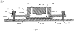
- Figure 1 shows a cross section of one embodiment of a direct contact fluid based cooling module for processors (100).
- a manifold (101) is disposed above a packaged computer processor (104).
- This packaged processor (104) is disposed on a printed circuit board (102), for example, by an array of pins (105).
- the manifold is configured with mounting holes or other features to allow fasteners (106) to fasten the manifold to a component or structure (here, the printed circuit board (102)) and not to mechanically affix to the processor (104).
- Such fastener attachment to the printed circuit board (102) may be accomplished using features (103) on or within the printed circuit board (102).
- Such features (103) may include, for example, holes with nuts, quarter-turn cam locks, or threaded inserts.
- the fasteners (106) may be configured for compatibility with standard processor mount specifications, for example, LGA-2011, LGA-1366, or LGA-2011, or common processor accessory mount patterns, for example, 80 mm square patterns. Of course, other methods are possible.
- the specific method of fastening the manifold (101) to the printed circuit board (102) is carefully selected to mate with existing circuit board features (103) for each processor technology.
- threaded screws (106) or quarter-turn fasteners may be used as the fastening method.
- the fastener may also include features to pre-load the manifold against the processor package, for example with compression springs (107) disposed between the manifold surface and the fastener bearing surface.
- the manifold When fastened to the printed circuit board (102), the manifold forms one or more leak-free seals (108) against a surface of the processor package.
- a leak-free seal is illustrated to contain fluid within the plenum (110) formed between the manifold and the processor surface (111).
- the one or more leak-free seals formed with the processor package may be accomplished by, for example, O-rings, gaskets, or elastomeric materials.
- a source of pressurized fluid is supplied to the manifold.
- the manifold includes one or more fluid inlets (109) to accept this source of pressurized fluid.
- the fluid fills and traverses internal cavity (110) before exiting the manifold through one or more exit ports (112). While flowing from inlet (109) to outlet (112), the fluid is in direct contact with, and flows over, processor surface (111). Heat is then transferred between the device surface and the fluid. This heat transfer may be used to cool the processor, without a need for thermal pastes or greases, or an additional large, finned heat sink.
- Manifold (101) may also include internal ribs or fins (113) for increased heat transfer area or fluid flow control. Such ribs or fins (113) may extend from the manifold into the fluid, or all the way to the device surface.
- a single-phase fluid is administered.
- This fluid may be any suitable coolant, including air, water, ethylene glycol, propylene glycol, ethanol, R134A, ammonia, or any other fluid. A combination of two or more of these fluids may also be used.
- the inlet (109) and outlet (112) may be of any type. They may also, for example, provide transmission to/from other components that require cooling. Such other components may be in neighboring parts of the assembly and may utilize transmission via tubing to other parts of the system.
- the inlet and outlet may interface with a fitting (e.g. barb, quick disconnect, compression), tubing, a manifold, or any other suitable method of interfacing fluids.
- Figure 2 shows a top view of one installation with a direct contact fluid manifold (201) disposed on a printed circuit board (202).
- the fluid manifold (201) is affixed to the circuit board by mechanical fasteners (206) and complementary features on the circuit board (not in view).
- the processor package (203) may be that, for example, of a CPU, GPU, ASIC, or FPGA.
- Also disposed on the circuit board (202), for example, may be other components (204) or electrical traces (205) that are not in mechanical or fluidic communication with the fluid manifold.
- a processor package In a volume between the fluid manifold (201) and the printed circuit board (202), there exists a processor package (203).
- the fluid manifold is in contact with at least one surface of the processor package and forms a leak-free seal.
- the fluid manifold does not mechanically fasten or affix to the processor package. This minimizes mechanical stress on the electrical component and simplifies the mounting architecture by instead leveraging standard mechanical mounting specifications for processor accessories that are found on many circuit boards.
- Figure 3 shows an isometric view of one possible embodiment of a direct contact fluid manifold for processors (300).
- the manifold is comprised of a center portion (306) which includes features for inlet and exit fluid plena (not shown due to viewing angle).
- a mounting flange (301) Extending beyond the central fluid plena portion (306) is a mounting flange (301) whose size is designed to conform to existing accessory mount patterns.
- Such mount patterns may be, for example, 80 mm square bolt patterns.
- Fastening to the accessory mount patterns may be accomplished using mechanical fasteners (302) which may be, for example, mechanical screws, quarter turn fasteners, or bolts.
- compression springs (303) may be disposed between the mount plate and the fastener to provide a compressive pre-load between the fluid manifold and the processor package, without requiring bearing of the fastener head (302) against the fluid manifold flange (301). This may be useful to prevent over-stressing the processor package by over-torqueing mechanical fasteners.
- other features may also be used including, for example, spacers, standoffs, shoulder screws, or binding barrels.
- Modular, direct contact fluid manifolds may be built from a variety of materials including, for example, metals, ceramics, and plastics.
- Fluid inlets/outlets may be of any typical form including, for example, barbed fittings, quick disconnects, press-to-connect fittings, or tubing pigtails.
- a single-phase fluid is administered to the fluid manifold.
- This fluid may be any suitable coolant, including air, water, ethylene glycol, propylene glycol, ethanol, R134A, ammonia, or any other fluid. A combination of two or more of these fluids may also be used.
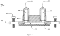
- Figure 4 shows a cross sectional view of a direct contact fluid manifold for processors (300).
- the manifold (401) brings cooling fluid in direct contact with the exterior surface (407) of the packaged processor (402).
- the manifold does not mechanically affix to the packaged processor (402).
- fasteners (302) mechanically affix the manifold to a circuit board (not shown).
- Fasteners (302) may be of many types as previously described.
- sealing features (403) e.g., an o-ring
- sealing features (403) e.g., an o-ring
- Cooling fluid is supplied by an external source of pressurized fluid. Fluid enters the manifold through one or more inlet ports (304) and fills the inlet plenum (406). Fluid then travels to a reservoir in contact with a surface (407) on the packaged processor (402). This reservoir is bounded by some combination of the manifold (401), one or more surface (407) of the processor, and seals (403). At the surface (407) of the processor (402), heat is transferred from the processor to the fluid. Cooling fluid then exits the manifold by traversing the exit plenum (408) and exiting the manifold through one or more exit ports (305).
- Figure 5 shows a bottom view of one embodiment of a direct contact fluid manifold for processors (500).
- the bottom view illustrates a possible configuration of the areas wetted by the fluid.
- the manifold (501) includes a center portion (503) that is wetted by fluid. Fluid enters and fills the wetted portion (503) through one or more fluid inlets (502), and later exits through one or more exit ports (505). Between inlet (502) and exit (505), in the wetted portion (503) may also be disposed features for enhancing the heat transfer. Such features may be area enhancements including, for example, fins or ribs (504).
- One or more seals (506) is disposed on the lower surface of the manifold (501) to aid in creating a leak-free barrier between the wetted portions (503) and the exterior.
- Figure 6 illustrates another embodiment of the fluid manifold with modular mounts for processors, where the fluid inlet and outlet are not in communication through the manifold.
- the manifold (601) may be disposed on a processor package (602) that includes internal flow channels (607) for the purpose of better cooling. Fluid enters the assembly (600) through one or more inlet ports (605) and fills an inlet plenum (606).
- the fluid in the inlet plenum (606) and the outlet plenum (608) are not in direct communication through the manifold (601). Instead, the fluid is passed through flow channels (607) within the interior of the processor package (602). This allows fluid to move between the inlet plenum (606) and the outlet plenum (608) before exiting through one or more exit ports (609).
- Seals (603) now serve to separate inlet fluid from outlet fluid, and from leaking to the exterior of the overall assembly.
- the manifold (601) is still mechanically affixed to a circuit board or other substrate (not shown) by fasteners (604) outside the extent of the processor (602), and not directly fastened to the processor.
- leak-free seals (603) are formed between the manifold (601) and the processor (602).
- Figure 7 shows a bottom view of one embodiment of a direct contact fluid manifold for processors (700). Fluid enters the manifold (701) through one or more inlet ports (702), filling the inlet plenum (703). This inlet plenum (703) is a wetted surface and is in communication with a surface of the processor, which would also be wetted by fluid.
- Seals (704) form a barrier between the inlet plenum (703) and the outlet plenum (705).
- the fluid passes through flow channels or conduits within the processor package, for example the channels (607) shown in Figure 6 .
- fluid fills the outlet plenum (705) and exits the manifold through one or more exit ports (706).
- Seals (704) also create a leak-free barrier between the outlet plenum (705) and the exterior of the assembly.
- Fasteners (707) affix the manifold (701) to the assembly, but outside the extents of the processor.
- the direct contact fluid manifold does not have to be a monolithic part. Assemblies may allow for the addition of heat transfer enhancing features to be included within the manifold. Such heat transfer enhancing features may include, for example, microjet cooling.
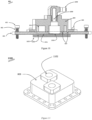
- Figure 8 illustrates a multiple-part direct contact fluid module assembly with internal microjet cooling features (800).
- the multiple-part assembly (800) of Figure 8 is comprised of a microjet mount plate (801), a reservoir cap (803), inlet and exit ports (805), and mechanical fasteners (802) to affix to the circuit board's accessory mounts. Fasteners (804) may also be used to attach different parts within the assembly (800).
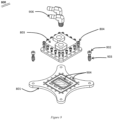
- Figure 9 depicts an exploded view of the fluid module assembly (800) such as that discussed in Figure 8 .
- a microjet mount plate (801) forms the primary mounting interface with the circuit board, for example, by bolts (802) which may have pre-loading components (903).
- a reservoir cap (803) creates a distinct inlet plenum and a distinct outlet plenum in communication with the microjet mount plate (801).
- the reservoir cap (803) and microjet mount plate (801) may be attached, for example, by fasteners (804).
- Fluid fittings (906) may be used for fluid conveyance into and out of the assembly.
- Gaskets (904) are used for establishing fluidic seals.
- Figure 10 shows a cross sectional view of one embodiment of a direct contact fluid module for processors (800). This embodiment features a multiple-part assembly that is also configured with direct contact microjet cooling of the processor.
- a microjet mount plate (801) forms part of the assembly along with a reservoir cap (803).
- the microjet mount plate and reservoir cap may be attached, for example, with mechanical fasteners (804).
- At least two internal volumes are formed by the reservoir cap and the microjet mount plate. At least one internal volume is filled with fluid from an inlet (1008).
- This inlet plenum (1009) contains higher-pressure inlet fluid.
- a microjet nozzle plate (1010) separates the higher-pressure inlet plenum (1009) from a lower-pressure outlet plenum (1012).
- the microjet nozzle plate (1010) is comprised of one or more orifices. The size of these orifices is carefully designed to balance pressure drop with heat transfer performance but may be, for example, 200 micrometers in diameter.
- the orifices may be circular in cross section or may be other shapes.
- the cooling fluid forms microjets directed at the surface (1011) of the packaged processor (1002). Fluid strikes the heat transfer surface (1011) of the packaged processor and fills the outlet plenum (1012). During this impingement, heat is transferred from the processor to the fluid. This process provides direct contact between the cooling fluid and an outer surface of the processor package. This approach eliminates the need for thermally conductive greases, a smooth heat transfer surface, and any additional conductive layers.
- Seals (1005 and 904) are disposed on and within the fluid module assembly. These seals separate inlet from outlet fluid and serve to create a leak-free barrier between fluid contained within the fluid module and the exterior. Seals may be of several types, including O-rings, gaskets, or elastomeric compounds. In this embodiment, the fluid directly contacts the surface of the processor package (1002) but does not penetrate within the processor package, as it may in other embodiments.
- the microjet mount plate (801) is affixed outside the extents of the processor (1002). Such installation may be by bolts (802) with pre-loading elements (903) or by other techniques. Mechanical fastening may be done to a printed circuit board, for example, to the board's accessory mounts. In all embodiments, the microjet mount plate (801) does not mechanically fasten to the processor package (1002) but does form a leak-free seal against at least one surface (1011) of the processor package (1002).
- Figure 11 illustrates an isometric view of one possible assembly (1100) comprising a reservoir cap (803) that may be used in a multiple-part fluid module assembly.
- a reservoir cap (803) that may be used in a multiple-part fluid module assembly.
- Within the reservoir cap (803) are formed at least two separate fluid plena. In the minimal case, these plena would act as part of an inlet plenum and an outlet plenum.
- Means of fluid ingress and egress may also be included on the cap, for example fluid ports (1102) for fittings, tubes, or other adapters.
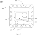
- Figure 12 shows a bottom view of an example of an assembly (1100) comprising a reservoir cap (803). At least two plena (1203, 1204) are formed within the reservoir cap.
- Inlet fluid for example, may enter through inlet port (1202) and fill the inlet plenum (1203). After passing through the microjet nozzle plate, the fluid fills an outlet plenum (1204) before being exhausted through one or more exit ports (1205).
- the reservoir cap (803) may be affixed to the microjet mount plate through a fastener pattern (1206). Seals are formed on sealing surfaces (1207) using gaskets (904).
- Figure 13 shows an isometric view of one example of an assembly (1300) comprising a microjet mount plate (801).
- Assembly (1300) is one part of a direct contact fluid module for processors.
- the fluid module may include a microjet mount plate (801) to increase the heat transfer performance of the assembly.
- the microjet mount plate (801) may include features, such as mechanical fasteners (802), that affix the fluid module to the circuit board or other assembly fixture.
- the inlet plenum (1203) contains higher-pressure fluid.
- One or more orifices on a microjet nozzle plate (1303) separate the inlet plenum from the outlet plenum. These orifices form the fluid microjets to produce direct contact fluid cooling on the processor located in proximity to the fluid module. After the transfer of heat to the microjet fluid, the fluid traverses the outlet plenum (1204). Seals (1005) create a leak-free barrier between the microjet mount plate and the adjacent processor surface.
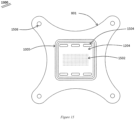
- Figure 14 shows a top view of a microjet mount plate instantiation (1300).
- Fluid may be supplied from a reservoir cap (803), forming at least two plena.
- An inlet plenum (1203) directs fluid through a microjet nozzle plate (1010), forming microjets that strike a surface of a processor package (1011) disposed beneath the microjet mount plate (801). During this process, heat is transferred to the fluid, which is then routed back up into one or more outlet plenum (1204).
- Seals (904) separate the inlet plenum (1203) from the outlet plenum (1204) and form a leak-free seal to the exterior. Multiple seals may be used, as shown in Figure 14 .
- microjet mount plate (801) is shown, in one example of a fluid module with integral microjet cooling (1500). This lower surface is the surface in proximity to the processor being cooled. Fluid passes through the microjet mount plate (801) by way of one or more microjet nozzles (1502) and fills the outlet plenum (1204). Fluid issuing from these nozzles impinges upon the direct contact surface of the processor, transferring heat and cooling the electronic device. This fluid then traverses the outlet plenum, moving through the microjet mount plate through outlet plenum passages (1504). The entire interior volume (that is, outlet plenum 1204) is wetted with cooling fluid in direct contact with a surface of the processor package.
- the microjet mount plate is affixed to a circuit board, for example, by a mechanical fastener pattern (1506) outside the extents of the processor.
- the microjet mount plate forms a leak-free seal using gaskets (1005) against the surface of the processor package but does not mechanically affix to the surface of the processor package.
- FIG 16 shows how the module depicted in Figures 9-15 would integrate into an assembly (1600) from an exploded isometric view.
- a heat generating element (1002) such as a computer processor, is disposed on a surface (1602), which may be the surface of a PCB or motherboard.
- Direct fluid contact cooling module (800) is attached to attachment features (1603), which are separate from the heat generating element (1002), via an attachment mechanism (802) such as pre-loaded fasteners.
- cooling fluid enters through inlet (1008), passes through the direct contact cooling module (800) to directly contact heat generating element (1002), and is exhausted through the outlet (1608). Fluid is contained between the direct contact cooling module (800) and heat generating element (1002) via a seal disposed on the underside of the direct contact cooling module (800) (obscured in image).
- Figures 17-20 depict another example of a direct contact cooling module.
- Figure 17A shows an isometric view
- Fig. 17B not forming part of the invention, a bottom view of a cooling housing (1701) forming part of a direct contact cooling module (2001).
- Cooling housing (1701) consists of an inlet port (1702) and an outlet port (1703), and a sealing lip (1704) to be used along with clamping plate (1901) ( Fig. 19 ) in transmitting force to create a fluid tight seal.
- the cooling housing (1704) has microjet nozzles (1705), in fluid communication with inlet port (1702), and outlet plenum passages (1706), in fluid communication with outlet port (1703).
- Figure 18 shows a partial isometric cross sectional view of the cooling housing (1701).
- an inlet port (1702) (obscured by cross section) is in fluid communication with microjet nozzles 1705, through which fluid passes to impact the surface of a heat generating electronic component (2004) ( Fig. 20 ).
- Fluid is exhausted through outlet plenum passages (1706) in fluid communication with the outlet port (1703).
- a sealing mechanism (1707) for example a gasket, o-ring, adhesive, or other, is disposed on the lower surface of the cooling housing (1701) to form a seal against the surface of a heat generating electronic component (2004).
- a sealing lip (1704) is present to accept a force if needed, for example via clamping plate (1901), in administering the sealing mechanism (1707).
- FIG 19 shows an embodiment of a clamping plate (1900) forming part of direct contact cooling module (2001).
- the clamping plate (1901) has a cutout (1902) meant to fit around a cooling housing (1701) so that the clamping plate (1901) can mate with cooling housing lip (1704).
- Clamping plate (1901) has at least one mechanism (1903) to accept a fastener or other attachment feature (2006).
- FIG 20 shows how the direct contact cooling module (2001), comprised of a cooling housing (1701) and a clamping plate (1901) as depicted in Figures 17-19 , would integrate into an assembly (2000) with an exploded isometric view.
- a heat generating element (2004) such as a computer processor, is disposed on a surface (2002), which may be the surface of a PCB or motherboard.
- Direct fluid contact cooling module (2001) is attached to attachment features (2003), which are separate from the heat generating element (2004), via an attachment mechanism (2006) such as pre-loaded fasteners.
- cooling fluid enters through inlet (2007), passes through the direct contact cooling module (2001) to directly contact heat generating element (2004), and is exhausted through the outlet (2008). Fluid is contained between the direct contact cooling module 2001 and heat generating element (1604) via a seal (1707) disposed on the underside of the cooling housing (1701) (obscured in image).
- Direct contact cooling modules (1601) and (2001) are example embodiments, of which the present invention is not limited to specific features or forms described. There may be direct contact cooling modules containing different methods of: forming the fluidic seal, attaching to the PCB or substrate, administering fluid onto the heat generating component, forming direct contact cooling modules, administering fluid in and out of the direct contact cooling module, establishing fluid communication within different parts of the direct contact cooling module, and others.
- Direct contact fluid modules may be of multiple pieces, or may be of a single unitary structure.
- Seals may be formed via o-rings, gaskets, adhesives, soldering, brazing, welding, or other permanent and non-permanent sealing mechanisms.
- PCB attachment may be done via fasteners, brackets, clamps, threaded rods and wingnuts, rivets, or other attachment mechanisms.
- Fluid may be administered directly onto the device surface to which the seal is made in a variety of different ways, including external contact of the surface, penetration into the surface, passing through the surface entirely, or other fluid disposing mechanisms to accomplish cooling.
- Fluidic supply and exhaust may be accomplished by way of fluid fittings, fluid conduits, direct tube attachment, an accompanying fluid manifold, or other fluid delivery techniques.
- inlet passageways and outlet passageways to deliver and exhaust fluid from the surface of the heat generating device
- microjet nozzles large non-restrictive inlet passageways, circular exit passageways, non-circular exit passageways, single exit passageways, a plurality of exit passageways, and other fluidic passageway configurations. Differences are not limited to those listed, and will be apparent to those skilled in the art without departing from the scope of the present invention.
- the microjet nozzles may be disposed in arrays so as to provide cooling for electronic devices of a range of different sizes. Such devices may contain length scales that range from 5-50mm, for example. Therefore, the size, location, and distribution of nozzles are carefully chosen to provide adequate cooling of the entire device.
- the nozzles may be disposed in linear arrays, circular arrays, or any other pattern that serves to help cover the surface of the heat-generating devices.
- the nozzles may be far apart or close together, details of which are carefully chosen in balancing thermofluidic considerations such as, for example, heat transfer and pressure drop.
- the heat may not be generated uniformly across the device surface to be cooled. Such sections of the surface where more heat is being generated are therefore more prone to increases in temperature, sometimes referred to as "hot spots". In these cases, it may be advantageous to concentrate nozzles nearer to the hot spots of higher heat generation, while having more sparsity in the array where there is lower or no heat generation. This allows for improved cooling efficiency, as better cooling occurs using the same amount of fluid flow, compared to a case where nozzles are uniformly disposed on the nozzle plate.
- each individual nozzle may vary across the array to balance tradeoffs of, for example, pressure, flow rate, and heat transfer, with the heat generating character of the electronic device. For example, a set of jets with lower heat transfer capability may be administered around areas of low heat generation, while jets with high heat transfer capability may be administered near hot spots.
- Figures 21A and 21B illustrate one possible implementation for matching hot spots on the device with the microjet-cooled direct contact fluid module.
- the heat generating device (2101) Fig. 21A may have one or more areas (2102) within it that are higher heat dissipation than the rest of the device.
- the microjet nozzle plate (2103) Fig. 21B may have an array of nozzles for cooling the device (2101). It may be beneficial to have a non-uniform distribution of nozzles, where nozzles may be arranged in a non-uniform way (2104) to provide better cooling to device hot spots (2102). In other areas, nozzle distribution may, for example, be more sparse (2105) where there is lower heat load, or they may be shaped or sized differently (2106). These non-uniform arrangements may produce more uniform temperatures on the device. This reduces the presence of thermal gradients across devices with non-uniform heat dissipations.
- the shape of the nozzle specifically can be carefully chosen to optimize thermofluidic properties, such as pressure drop, flow rate, and heat transfer capability.
- Figures 22A and 22B show one example, where a jet nozzle plate (2201) of thickness (2202) has an array of microjet nozzles (2203). By taking a cross section of the nozzle plate (2201), as in Fig. 22B , the nozzle shape becomes visible. By including a chamfered edge (2204) on the jet nozzles (2203), enhanced fluid flow can result by reducing pressure drop with minimal impact on fluid flow and heat transfer. Note that the geometric features of the chamfer such as angle, depth, and diameter are chosen to produce an optimal desired result.
- a fluid module provides direct fluid contact cooling of processors.
- the fluid module features mounts that are configured to avoid mechanical fastening to the processor package while still forming a leak-free seal with a surface on the processor package. Mechanical fastening is done outside the extents of the processor, for example with existing circuit board mounts.
- This approach provides direct contact fluid cooling, minimizes mechanical stress on the processor package, and leverages common printed circuit board accessory mounting features.
- the direct contact fluid module reduces the thermal path for heat that is generated by the processor, using the processor's own surface or surfaces as the heat transfer interface. Direct contact fluid modules are designed to be used with many commonly available processor packages on printed circuit boards with accessory mounting patterns.
- the present disclosure discusses a method of thermal management of computer processors by direct fluid-contact cooling.
- the fluid module is disposed over a computer processor.
- the module attachment produces a leak-free seal between the module and a surface of the processor but does not mechanically fasten to the processor.
- Coolant fluid passes within the module, making direct contact with at least one surface of the processor.
- fluid contact with the processor may be in the form of impinging microjets formed by the module.
- fluid contact may not be limited to an external processor surface, but may occur with coolant flowing through passages within the processor.
- heat is transferred from the processor to the fluid making direct contact with the surface(s) of the packaged processor. The fluid then exits the module.
Landscapes
- Engineering & Computer Science (AREA)
- Microelectronics & Electronic Packaging (AREA)
- Physics & Mathematics (AREA)
- Computer Hardware Design (AREA)
- Condensed Matter Physics & Semiconductors (AREA)
- General Physics & Mathematics (AREA)
- Power Engineering (AREA)
- Thermal Sciences (AREA)
- General Engineering & Computer Science (AREA)
- Cooling Or The Like Of Electrical Apparatus (AREA)
- Cooling Or The Like Of Semiconductors Or Solid State Devices (AREA)
Description
- This application claims priority of Provisional Patent Application
62/833,745, filed on April 14, 2019 - The present invention relates to a direct-contact single-phase fluid-based cooling module for fluidly cooling an electronic component.
- This disclosure relates to cooling of electronic components.
- Fueled by data, machine learning, virtual reality, and artificial intelligence, the demand for processing power continues to increase. Modern data centers, for instance, host racks of hundreds or thousands of individual processors (e.g., CPUs, GPUs, or ASICs). In this quest for greater computational power, advances in fabrication processes have allowed chip designers to build smaller processors with higher power density. With this increase in power density comes the need to remove the heat that is dissipated from these devices.
- Current approaches to cooling computer processors involve the attachment of a metal heat sink (liquid- or air-cooled) to the processor package by using a thermal paste and then fastening the metal heat sink to standard mounting patterns located on the circuit board that hosts the processor. These strategies have been effective but suffer from performance that cannot keep pace with processor power advancements. Further, these solutions require large, heavy, expensive metal heat sinks to help dissipate the heat. Their large size and weight can stress the processor package and circuit board. Continued growth of these heat sinks further limits the achievable packing density of processors in data centers, computer cases, and application-specific printed circuit boards.
- Traditional approaches also use a thermal paste to thermally attach these large heat sinks. Using thermal paste to attach heat sinks to electronic devices produces an assembly with an overall effectiveness that hinges on the durability and lifetime of the thermal paste that connects the heat sink to the processor's package. Degradation of this thermal paste over time can lead to reduced performance, or device failure.
-
EP3188230A1 describes a liquid cooling system for cooling an electronic device.US 2006/0250774 A1 describes a cooling apparatus and method of fabrication.US 2014/0126150 A1 describes a heat dissipation lid.US 2006/0042825 A1 describes a structure and method of forming and cooling the structure. - It would, therefore, be useful to have a processor heat sink that: had greater thermal performance; came in a compact package size; eliminated the need for thermal paste; and could be used with existing and future processor mechanical mount specifications. The invention is set out in the appended set of claims.
- In one aspect, a direct-contact single-phase fluid-based cooling module is provided for cooling an electronic component that is mounted to a printed circuit board (PCB). The cooling module includes a manifold comprising a fluid inlet that is fluidly coupled to a fluid outlet. The manifold is configured to be removably coupled to the PCB. The cooling module further comprises manifold mounting structures that are configured to removably couple the manifold to the PCB. The cooling module further comprises a separable fluid-tight seal between the manifold and the electronic component, wherein when a fluid is passed through the manifold the fluid directly contacts the electronic component. The manifold further comprises a fluid plenum that fluidly couples the fluid inlet and the fluid outlet, wherein the fluid plenum contacts the surface of the electronic component. The manifold further comprises a nozzle plate that defines a plurality of orifices that are configured to create jets that are directed at the surface of the electronic component. Orifices of the plurality of orifices are configured non-uniformly across the nozzle plate to provide more effective cooling for reduction of temperature gradients in the electronic component.
- Some examples include one of the above and/or below features, or any combination thereof. In an example the manifold mounting structures are located outside the extent of the adjacent electronic component to be cooled. In an example fluid contacts only exterior surfaces of the electronic component. In an example the fluid passes from the inlet, within the electronic component, and to the outlet, for purposes of better heat transfer. In some examples the manifold mounting structures are configured to fix the manifold to a printed circuit board. In an example the manifold mounting structures are configured to fix the manifold to a processor accessory mount pattern of the printed circuit board.
- Some examples include one of the above and/or below features, or any combination thereof. In an example the manifold mounting structures comprise a pre-loading component to produce a robust seal on the electronic component. In an example the direct-contact fluid-based cooling module further includes a compressible sealing element between the manifold and the electronic component, to facilitate the fluid-tight seal. In an example the manifold further comprises internal ribs or fins that increase a surface area of the manifold that is exposed to the fluid or enhance fluid flow, for enhancing heat transfer. In an example the inlet and outlet are in fluid communication with fluid fittings. In an example the inlet and outlet are in fluid communication with fluid conduits.
- Some examples include one of the above and/or below features, or any combination thereof. In an example the nozzle plate divides the fluid plenum into an inlet plenum and an outlet plenum, wherein the fluid pressure is lower in the outlet plenum than it is in the inlet plenum. In an example the nozzle plate further defines at least one outlet fluid passageway that is configured to conduct fluid from the outlet plenum toward the fluid outlet of the manifold. In an example a perimeter can be drawn around the plurality of orifices without enclosing any of the outlet fluid passageways. In some examples the orifices contain chamfers on a surface of the plate. In an example the orifices form microjet nozzles. In an example the microjet nozzles direct the fluid in a direction substantially perpendicular to a surface of the nozzle plate, to create fluid flow with substantially high momentum in the perpendicular direction. In an example, the manifold is formed form a material having a low thermal conductivity. In another example, the fluid-tight seal is thermally non-conductive. In another example, the size and shape of each orifice from the plurality of orifices varies across the array.
- For a better understanding of the present disclosure, reference is made to the accompanying drawings, in which:
-
FIG. 1 shows a cross sectional view of a direct contact fluid based cooling module, not forming part of the invention, disposed on a CPU and attached to the CPU motherboard. -
FIG. 2 shows a top view of a direct contact fluid based cooling module, disposed on a CPU and attached to the CPU motherboard. -
FIG. 3 shows an isometric view of one embodiment of a direct contact fluid based cooling module for delivering fluid to the surface of a CPU package. -
FIG. 4 shows a cross sectional view of a direct contact fluid based cooling module, not forming part of the invention, where cooling fluid is delivered to contact a CPU package's exterior surface. -
FIG. 5 shows a bottom view of a direct contact fluid based cooling module, not forming part of the invention, where the fluid-filled cavity in contact with the CPU package may have cooling or flow enhancing features. -
FIG. 6 shows a cross sectional view of the direct contact fluid based cooling module, not forming part of the invention, where fluid is supplied to the CPU package for delivery within the CPU package. -
FIG. 7 shows a bottom view of one embodiment of a direct contact fluid based cooling module for processors, where the supply/receive reservoirs are separate to provide/receive coolant fluid to/from the CPU package. -
FIG. 8 shows an isometric view of another embodiment of a direct contact fluid based cooling module which contains internal features to produce high performance microjet cooling on the exterior surface of a CPU package. -
FIG. 9 shows an exploded view of one embodiment of a direct contact fluid based cooling module which contains internal features to produce high performance microjet cooling on the exterior surface of a CPU package. -
FIG. 10 shows a cross sectional view of one embodiment of a direct contact fluid based cooling module with microjet cooling of the exterior surface of a CPU package. -
FIG. 11 shows a reservoir cap that may comprise one segment of a direct contact fluid based cooling module for processors. -
FIG. 12 shows a bottom view of the reservoir cap ofFigure 11 , illustrating the separate inlet and outlet fluid reservoir sections. -
FIG. 13 shows an isometric view of a microjet mounting plate, not forming part of the invention, that may comprise one segment of a direct contact fluid based cooling module for processors. -
FIG. 14 shows a top view of a microjet mounting plate, not forming part of the invention, with microjet cooling features. -
FIG. 15 shows a bottom view of a microjet mounting plate, not forming part of the invention, with microjet cooling features. -
FIG. 16 shows an isometric exploded assembly view depicting a microjet direct contact fluid module interfacing with the electronic device and mounting board. -
FIGs. 17A and 17B show a microjet direct contact fluid module, not forming part of the invention, with the microjet features built into the reservoir cap, in isometric and bottom views. -
FIG. 18 shows a cross sectional view taken along line 18-18,Fig. 17A , of a reservoir cap in an alternative microjet direct contact fluid module not forming part of the invention. -
FIG. 19 shows an isometric view of a clamping plate used in an alternative embodiment to attach to the mounting pattern and create a seal. -
FIG. 20 shows an isometric exploded assembly view of an alternative embodiment. -
FIGs. 21A and21B show how embodiments of the direct contact fluid module containing microjets may be distributed so as to provide non-uniform cooling. -
FIGs. 22A and 22B show how embodiments of the direct contact fluid module, not forming part of the invention, containing microjets may be configured to have chamfers for improved fluid performance, whereFig. 22B is a cross-section taken alongline 22B-22B,Fig. 22A . - This disclosure describes the use of a structure (e.g., a mounting plate) with an integral fluid module designed to deliver coolant fluid in direct contact with the surface of a computer processor package. In an example the structure is a mounting plate that is configured to form a leak-free seal against the processor package, while fastening to common accessory mounting features on a host printed circuit board for the processor. The disclosure further describes several non-limiting embodiments of the direct contact fluid-based cooling modules, including those for cooling the exterior surface of a computer processor package. Commonly available accessory mounts found on printed circuit boards can be used to introduce a compact way to deliver cooling fluid in direct contact with the exterior surface of a computer processor package, while maintaining modularity across many types of processor packages.
- Many computer processor assemblies involve a packaged semiconductor device that is installed onto a printed circuit board. Encapsulating this semiconductor device is a cover that may serve several purposes including mechanical protection and heat transfer. Regarding heat transfer, this cover is oftentimes insufficient by itself to dissipate the heat from the processor, and a large, finned, metal heat sink is then attached. This approach leads to complex, low performance, large overall implementations.
- Yet other approaches involve liquid cooling of the computer processor. Here, the greater heat transfer abilities of liquids are exploited, traditionally by passing the cooling liquid through a finned, conductive metal heat exchanger that is attached to the processor by a thermal paste or epoxy. These approaches , too, include the separate, large heat sinks of other approaches, but use a pressurized liquid instead of air as the cooling medium. This leads to more capable thermal solutions, but still uses a large, expensive, metal package that relies on thermal paste to couple the thermal management solution to the device.
- As opposed to a separate liquid heat exchanger, direct contact cooling as disclosed herein can provide high performance cooling without the need for thermal pastes. Microjet cooling, for example, is a technique for cooling high-power devices that is characterized by fluid moving through a nozzle to form a small jet of fluid with substantially greater momentum in one direction than another. When this high-momentum fluid impacts a surface, it suppresses the thermal boundary layer at that surface, producing very high heat transfer at that spot. Microjet cooling technology has been demonstrated to produce heat transfer coefficients in excess of 200,000 W/m2K, more than ten times that of competing approaches (e.g., microchannels ≈ 20,000 W/m2K). This allows the fluid to collect more heat, without the need for additional metal heat spreaders or thermal pastes. Microjet cooling is further described in
US Patent Application Publication 2019/0013258 and International Patent Application PublicationWO 2019/018597 . - In one non-limiting aspect of the present disclosure, direct contact microjet cooling is configured within a fluid module, with modular mounts for computer CPUs. In an example the assembly is fastened not to the processor, but to the printed circuit board that hosts the processor. During the installation, a leak-free seal is formed between the fluid module and the processor, where direct contact fluid cooling by microjet impingement is produced on the surface of the processor package. This approach yields high-performance cooling in a compact size, eliminates the need for thermal pastes, and does not fasten to the individual processor but instead to existing mounting features on many printed circuit boards, thus achieving greater modularity.
- This disclosure is not limited to the use of microjet cooling. Rather, the disclosure describes direct contact fluidic cooling of computer processors (CPUs, GPUs, FPGAs, ASICs, etc.) using a fluid module with modular mounts that fasten to the processor motherboard, while also forming a leak-free seal against at least one surface of the processor package.
-
Figure 1 , not forming part of the invention, shows a cross section of one embodiment of a direct contact fluid based cooling module for processors (100). A manifold (101) is disposed above a packaged computer processor (104). This packaged processor (104) is disposed on a printed circuit board (102), for example, by an array of pins (105). Of course, other methods of attaching the processor (104) to the circuit board (102) may be used, including a combination of different methods. The manifold is configured with mounting holes or other features to allow fasteners (106) to fasten the manifold to a component or structure (here, the printed circuit board (102)) and not to mechanically affix to the processor (104). Such fastener attachment to the printed circuit board (102) may be accomplished using features (103) on or within the printed circuit board (102). Such features (103) may include, for example, holes with nuts, quarter-turn cam locks, or threaded inserts. For widespread applicability and modularity, the fasteners (106) may be configured for compatibility with standard processor mount specifications, for example, LGA-2011, LGA-1366, or LGA-2011, or common processor accessory mount patterns, for example, 80 mm square patterns. Of course, other methods are possible. - The specific method of fastening the manifold (101) to the printed circuit board (102) is carefully selected to mate with existing circuit board features (103) for each processor technology. For example, threaded screws (106) or quarter-turn fasteners may be used as the fastening method. The fastener may also include features to pre-load the manifold against the processor package, for example with compression springs (107) disposed between the manifold surface and the fastener bearing surface.
- When fastened to the printed circuit board (102), the manifold forms one or more leak-free seals (108) against a surface of the processor package. In
Figure 1 , a leak-free seal is illustrated to contain fluid within the plenum (110) formed between the manifold and the processor surface (111). The one or more leak-free seals formed with the processor package may be accomplished by, for example, O-rings, gaskets, or elastomeric materials. - In operation, a source of pressurized fluid is supplied to the manifold. The manifold includes one or more fluid inlets (109) to accept this source of pressurized fluid. The fluid fills and traverses internal cavity (110) before exiting the manifold through one or more exit ports (112). While flowing from inlet (109) to outlet (112), the fluid is in direct contact with, and flows over, processor surface (111). Heat is then transferred between the device surface and the fluid. This heat transfer may be used to cool the processor, without a need for thermal pastes or greases, or an additional large, finned heat sink. Manifold (101) may also include internal ribs or fins (113) for increased heat transfer area or fluid flow control. Such ribs or fins (113) may extend from the manifold into the fluid, or all the way to the device surface.
- In use, a single-phase fluid is administered. This fluid may be any suitable coolant, including air, water, ethylene glycol, propylene glycol, ethanol, R134A, ammonia, or any other fluid. A combination of two or more of these fluids may also be used.
- The inlet (109) and outlet (112) may be of any type. They may also, for example, provide transmission to/from other components that require cooling. Such other components may be in neighboring parts of the assembly and may utilize transmission via tubing to other parts of the system. The inlet and outlet may interface with a fitting (e.g. barb, quick disconnect, compression), tubing, a manifold, or any other suitable method of interfacing fluids.
-
Figure 2 shows a top view of one installation with a direct contact fluid manifold (201) disposed on a printed circuit board (202). The fluid manifold (201) is affixed to the circuit board by mechanical fasteners (206) and complementary features on the circuit board (not in view). Disposed on the printed circuit board (202), and between the circuit board and the fluid manifold (201), is a processor package (203). The processor package (203) may be that, for example, of a CPU, GPU, ASIC, or FPGA. Also disposed on the circuit board (202), for example, may be other components (204) or electrical traces (205) that are not in mechanical or fluidic communication with the fluid manifold. - In a volume between the fluid manifold (201) and the printed circuit board (202), there exists a processor package (203). The fluid manifold is in contact with at least one surface of the processor package and forms a leak-free seal. However, the fluid manifold does not mechanically fasten or affix to the processor package. This minimizes mechanical stress on the electrical component and simplifies the mounting architecture by instead leveraging standard mechanical mounting specifications for processor accessories that are found on many circuit boards.
-
Figure 3 shows an isometric view of one possible embodiment of a direct contact fluid manifold for processors (300). The manifold is comprised of a center portion (306) which includes features for inlet and exit fluid plena (not shown due to viewing angle). Extending beyond the central fluid plena portion (306) is a mounting flange (301) whose size is designed to conform to existing accessory mount patterns. Such mount patterns may be, for example, 80 mm square bolt patterns. Fastening to the accessory mount patterns may be accomplished using mechanical fasteners (302) which may be, for example, mechanical screws, quarter turn fasteners, or bolts. - Other features may be included to aid the mechanical fastening of the fluid manifold to the circuit board. For example, compression springs (303) may be disposed between the mount plate and the fastener to provide a compressive pre-load between the fluid manifold and the processor package, without requiring bearing of the fastener head (302) against the fluid manifold flange (301). This may be useful to prevent over-stressing the processor package by over-torqueing mechanical fasteners. Of course, other features may also be used including, for example, spacers, standoffs, shoulder screws, or binding barrels.
- Because the cooling is accomplished through direct contact between the fluid and the device to be cooled, effective heat transfer can be achieved even with manifolds constructed from materials that are not thermally conductive. Modular, direct contact fluid manifolds may be built from a variety of materials including, for example, metals, ceramics, and plastics.
- In operation, fluid is supplied to the fluid manifold by one or more fluid inlets (304), while the fluid is exhausted through one or more fluid outlets (305). Fluid inlets/outlets may be of any typical form including, for example, barbed fittings, quick disconnects, press-to-connect fittings, or tubing pigtails.
- A single-phase fluid is administered to the fluid manifold. This fluid may be any suitable coolant, including air, water, ethylene glycol, propylene glycol, ethanol, R134A, ammonia, or any other fluid. A combination of two or more of these fluids may also be used.
-
Figure 4 , not forming part of the invention, shows a cross sectional view of a direct contact fluid manifold for processors (300). The manifold (401) brings cooling fluid in direct contact with the exterior surface (407) of the packaged processor (402). The manifold does not mechanically affix to the packaged processor (402). Instead, fasteners (302) mechanically affix the manifold to a circuit board (not shown). Fasteners (302) may be of many types as previously described. During the mechanical fastening, sealing features (403) (e.g., an o-ring) disposed on the manifold form a leak-free seal between the manifold (401) and the packaged processor (402). - Cooling fluid is supplied by an external source of pressurized fluid. Fluid enters the manifold through one or more inlet ports (304) and fills the inlet plenum (406). Fluid then travels to a reservoir in contact with a surface (407) on the packaged processor (402). This reservoir is bounded by some combination of the manifold (401), one or more surface (407) of the processor, and seals (403). At the surface (407) of the processor (402), heat is transferred from the processor to the fluid. Cooling fluid then exits the manifold by traversing the exit plenum (408) and exiting the manifold through one or more exit ports (305).
-
Figure 5 , not forming part of the invention, shows a bottom view of one embodiment of a direct contact fluid manifold for processors (500). The bottom view illustrates a possible configuration of the areas wetted by the fluid. The manifold (501) includes a center portion (503) that is wetted by fluid. Fluid enters and fills the wetted portion (503) through one or more fluid inlets (502), and later exits through one or more exit ports (505). Between inlet (502) and exit (505), in the wetted portion (503) may also be disposed features for enhancing the heat transfer. Such features may be area enhancements including, for example, fins or ribs (504). One or more seals (506) is disposed on the lower surface of the manifold (501) to aid in creating a leak-free barrier between the wetted portions (503) and the exterior. - While the fluid path between the inlet and outlet have been shown as a continuous reservoir in
Figure 4 , this disclosure is not limited to such configurations. For example,Figure 6 illustrates another embodiment of the fluid manifold with modular mounts for processors, where the fluid inlet and outlet are not in communication through the manifold. - As shown in
Figure 6 , not forming part of the invention, with assembly (600) the manifold (601) may be disposed on a processor package (602) that includes internal flow channels (607) for the purpose of better cooling. Fluid enters the assembly (600) through one or more inlet ports (605) and fills an inlet plenum (606). Here, however, the fluid in the inlet plenum (606) and the outlet plenum (608) are not in direct communication through the manifold (601). Instead, the fluid is passed through flow channels (607) within the interior of the processor package (602). This allows fluid to move between the inlet plenum (606) and the outlet plenum (608) before exiting through one or more exit ports (609). Seals (603) now serve to separate inlet fluid from outlet fluid, and from leaking to the exterior of the overall assembly. Notably, the manifold (601) is still mechanically affixed to a circuit board or other substrate (not shown) by fasteners (604) outside the extent of the processor (602), and not directly fastened to the processor. However, leak-free seals (603) are formed between the manifold (601) and the processor (602). -
Figure 7 shows a bottom view of one embodiment of a direct contact fluid manifold for processors (700). Fluid enters the manifold (701) through one or more inlet ports (702), filling the inlet plenum (703). This inlet plenum (703) is a wetted surface and is in communication with a surface of the processor, which would also be wetted by fluid. - Seals (704) form a barrier between the inlet plenum (703) and the outlet plenum (705). To traverse between the inlet plenum (703) and the outlet plenum (705), the fluid passes through flow channels or conduits within the processor package, for example the channels (607) shown in
Figure 6 . After passing through the interior of the processor package and being returned to the manifold, fluid fills the outlet plenum (705) and exits the manifold through one or more exit ports (706). Seals (704) also create a leak-free barrier between the outlet plenum (705) and the exterior of the assembly. Fasteners (707) affix the manifold (701) to the assembly, but outside the extents of the processor. - The direct contact fluid manifold does not have to be a monolithic part. Assemblies may allow for the addition of heat transfer enhancing features to be included within the manifold. Such heat transfer enhancing features may include, for example, microjet cooling.
Figure 8 illustrates a multiple-part direct contact fluid module assembly with internal microjet cooling features (800). - The multiple-part assembly (800) of
Figure 8 is comprised of a microjet mount plate (801), a reservoir cap (803), inlet and exit ports (805), and mechanical fasteners (802) to affix to the circuit board's accessory mounts. Fasteners (804) may also be used to attach different parts within the assembly (800). -
Figure 9 depicts an exploded view of the fluid module assembly (800) such as that discussed inFigure 8 . A microjet mount plate (801) forms the primary mounting interface with the circuit board, for example, by bolts (802) which may have pre-loading components (903). A reservoir cap (803) creates a distinct inlet plenum and a distinct outlet plenum in communication with the microjet mount plate (801). The reservoir cap (803) and microjet mount plate (801) may be attached, for example, by fasteners (804). Fluid fittings (906) may be used for fluid conveyance into and out of the assembly. Gaskets (904) are used for establishing fluidic seals. -
Figure 10 shows a cross sectional view of one embodiment of a direct contact fluid module for processors (800). This embodiment features a multiple-part assembly that is also configured with direct contact microjet cooling of the processor. - A microjet mount plate (801) forms part of the assembly along with a reservoir cap (803). The microjet mount plate and reservoir cap may be attached, for example, with mechanical fasteners (804). At least two internal volumes are formed by the reservoir cap and the microjet mount plate. At least one internal volume is filled with fluid from an inlet (1008). This inlet plenum (1009) contains higher-pressure inlet fluid. A microjet nozzle plate (1010) separates the higher-pressure inlet plenum (1009) from a lower-pressure outlet plenum (1012). The microjet nozzle plate (1010) is comprised of one or more orifices. The size of these orifices is carefully designed to balance pressure drop with heat transfer performance but may be, for example, 200 micrometers in diameter. The orifices may be circular in cross section or may be other shapes.
- As fluid passes through the microjet nozzle plate (1010), the cooling fluid forms microjets directed at the surface (1011) of the packaged processor (1002). Fluid strikes the heat transfer surface (1011) of the packaged processor and fills the outlet plenum (1012). During this impingement, heat is transferred from the processor to the fluid. This process provides direct contact between the cooling fluid and an outer surface of the processor package. This approach eliminates the need for thermally conductive greases, a smooth heat transfer surface, and any additional conductive layers.
- Seals (1005 and 904) are disposed on and within the fluid module assembly. These seals separate inlet from outlet fluid and serve to create a leak-free barrier between fluid contained within the fluid module and the exterior. Seals may be of several types, including O-rings, gaskets, or elastomeric compounds. In this embodiment, the fluid directly contacts the surface of the processor package (1002) but does not penetrate within the processor package, as it may in other embodiments.
- In all embodiments, the microjet mount plate (801) is affixed outside the extents of the processor (1002). Such installation may be by bolts (802) with pre-loading elements (903) or by other techniques. Mechanical fastening may be done to a printed circuit board, for example, to the board's accessory mounts. In all embodiments, the microjet mount plate (801) does not mechanically fasten to the processor package (1002) but does form a leak-free seal against at least one surface (1011) of the processor package (1002).
-
Figure 11 illustrates an isometric view of one possible assembly (1100) comprising a reservoir cap (803) that may be used in a multiple-part fluid module assembly. Within the reservoir cap (803) are formed at least two separate fluid plena. In the minimal case, these plena would act as part of an inlet plenum and an outlet plenum. Means of fluid ingress and egress may also be included on the cap, for example fluid ports (1102) for fittings, tubes, or other adapters. -
Figure 12 shows a bottom view of an example of an assembly (1100) comprising a reservoir cap (803). At least two plena (1203, 1204) are formed within the reservoir cap. Inlet fluid, for example, may enter through inlet port (1202) and fill the inlet plenum (1203). After passing through the microjet nozzle plate, the fluid fills an outlet plenum (1204) before being exhausted through one or more exit ports (1205). The reservoir cap (803) may be affixed to the microjet mount plate through a fastener pattern (1206). Seals are formed on sealing surfaces (1207) using gaskets (904). -
Figure 13 , not forming part of the invention, shows an isometric view of one example of an assembly (1300) comprising a microjet mount plate (801). Assembly (1300) is one part of a direct contact fluid module for processors. The fluid module may include a microjet mount plate (801) to increase the heat transfer performance of the assembly. The microjet mount plate (801) may include features, such as mechanical fasteners (802), that affix the fluid module to the circuit board or other assembly fixture. - Within the extent of the microjet mount plate (801) exists an inlet plenum (1203), which may be supplied fluid from, for example, the reservoir cap (803). The inlet plenum (1203) contains higher-pressure fluid. One or more orifices on a microjet nozzle plate (1303) separate the inlet plenum from the outlet plenum. These orifices form the fluid microjets to produce direct contact fluid cooling on the processor located in proximity to the fluid module. After the transfer of heat to the microjet fluid, the fluid traverses the outlet plenum (1204). Seals (1005) create a leak-free barrier between the microjet mount plate and the adjacent processor surface.
-
Figure 14 , not forming part of the invention, shows a top view of a microjet mount plate instantiation (1300). Fluid may be supplied from a reservoir cap (803), forming at least two plena. An inlet plenum (1203) directs fluid through a microjet nozzle plate (1010), forming microjets that strike a surface of a processor package (1011) disposed beneath the microjet mount plate (801). During this process, heat is transferred to the fluid, which is then routed back up into one or more outlet plenum (1204). - Seals (904) separate the inlet plenum (1203) from the outlet plenum (1204) and form a leak-free seal to the exterior. Multiple seals may be used, as shown in
Figure 14 . - In
Figure 15 , not forming part of the invention, the lower surface of microjet mount plate (801) is shown, in one example of a fluid module with integral microjet cooling (1500). This lower surface is the surface in proximity to the processor being cooled. Fluid passes through the microjet mount plate (801) by way of one or more microjet nozzles (1502) and fills the outlet plenum (1204). Fluid issuing from these nozzles impinges upon the direct contact surface of the processor, transferring heat and cooling the electronic device. This fluid then traverses the outlet plenum, moving through the microjet mount plate through outlet plenum passages (1504). The entire interior volume (that is, outlet plenum 1204) is wetted with cooling fluid in direct contact with a surface of the processor package. The microjet mount plate is affixed to a circuit board, for example, by a mechanical fastener pattern (1506) outside the extents of the processor. The microjet mount plate forms a leak-free seal using gaskets (1005) against the surface of the processor package but does not mechanically affix to the surface of the processor package. -
Figure 16 shows how the module depicted inFigures 9-15 would integrate into an assembly (1600) from an exploded isometric view. A heat generating element (1002), such as a computer processor, is disposed on a surface (1602), which may be the surface of a PCB or motherboard. Direct fluid contact cooling module (800) is attached to attachment features (1603), which are separate from the heat generating element (1002), via an attachment mechanism (802) such as pre-loaded fasteners. In operation, cooling fluid enters through inlet (1008), passes through the direct contact cooling module (800) to directly contact heat generating element (1002), and is exhausted through the outlet (1608). Fluid is contained between the direct contact cooling module (800) and heat generating element (1002) via a seal disposed on the underside of the direct contact cooling module (800) (obscured in image). -
Figures 17-20 depict another example of a direct contact cooling module.Figure 17A , not forming part of the invention, shows an isometric view andFig. 17B , not forming part of the invention, a bottom view of a cooling housing (1701) forming part of a direct contact cooling module (2001). Cooling housing (1701) consists of an inlet port (1702) and an outlet port (1703), and a sealing lip (1704) to be used along with clamping plate (1901) (Fig. 19 ) in transmitting force to create a fluid tight seal. The cooling housing (1704) has microjet nozzles (1705), in fluid communication with inlet port (1702), and outlet plenum passages (1706), in fluid communication with outlet port (1703). -
Figure 18 , not forming part of the invention, shows a partial isometric cross sectional view of the cooling housing (1701). In operation, an inlet port (1702) (obscured by cross section) is in fluid communication withmicrojet nozzles 1705, through which fluid passes to impact the surface of a heat generating electronic component (2004) (Fig. 20 ). Fluid is exhausted through outlet plenum passages (1706) in fluid communication with the outlet port (1703). A sealing mechanism (1707), for example a gasket, o-ring, adhesive, or other, is disposed on the lower surface of the cooling housing (1701) to form a seal against the surface of a heat generating electronic component (2004). A sealing lip (1704) is present to accept a force if needed, for example via clamping plate (1901), in administering the sealing mechanism (1707). -
Figure 19 shows an embodiment of a clamping plate (1900) forming part of direct contact cooling module (2001). The clamping plate (1901) has a cutout (1902) meant to fit around a cooling housing (1701) so that the clamping plate (1901) can mate with cooling housing lip (1704). Clamping plate (1901) has at least one mechanism (1903) to accept a fastener or other attachment feature (2006). -
Figure 20 shows how the direct contact cooling module (2001), comprised of a cooling housing (1701) and a clamping plate (1901) as depicted inFigures 17-19 , would integrate into an assembly (2000) with an exploded isometric view. A heat generating element (2004), such as a computer processor, is disposed on a surface (2002), which may be the surface of a PCB or motherboard. Direct fluid contact cooling module (2001) is attached to attachment features (2003), which are separate from the heat generating element (2004), via an attachment mechanism (2006) such as pre-loaded fasteners. In operation, cooling fluid enters through inlet (2007), passes through the direct contact cooling module (2001) to directly contact heat generating element (2004), and is exhausted through the outlet (2008). Fluid is contained between the directcontact cooling module 2001 and heat generating element (1604) via a seal (1707) disposed on the underside of the cooling housing (1701) (obscured in image). - Direct contact cooling modules (1601) and (2001) are example embodiments, of which the present invention is not limited to specific features or forms described. There may be direct contact cooling modules containing different methods of: forming the fluidic seal, attaching to the PCB or substrate, administering fluid onto the heat generating component, forming direct contact cooling modules, administering fluid in and out of the direct contact cooling module, establishing fluid communication within different parts of the direct contact cooling module, and others.
- Direct contact fluid modules may be of multiple pieces, or may be of a single unitary structure. Seals may be formed via o-rings, gaskets, adhesives, soldering, brazing, welding, or other permanent and non-permanent sealing mechanisms. PCB attachment may be done via fasteners, brackets, clamps, threaded rods and wingnuts, rivets, or other attachment mechanisms. Fluid may be administered directly onto the device surface to which the seal is made in a variety of different ways, including external contact of the surface, penetration into the surface, passing through the surface entirely, or other fluid disposing mechanisms to accomplish cooling. Fluidic supply and exhaust may be accomplished by way of fluid fittings, fluid conduits, direct tube attachment, an accompanying fluid manifold, or other fluid delivery techniques. There may be different layouts of inlet passageways and outlet passageways to deliver and exhaust fluid from the surface of the heat generating device, such as microjet nozzles, large non-restrictive inlet passageways, circular exit passageways, non-circular exit passageways, single exit passageways, a plurality of exit passageways, and other fluidic passageway configurations. Differences are not limited to those listed, and will be apparent to those skilled in the art without departing from the scope of the present invention.
- In certain embodiments, the microjet nozzles may be disposed in arrays so as to provide cooling for electronic devices of a range of different sizes. Such devices may contain length scales that range from 5-50mm, for example. Therefore, the size, location, and distribution of nozzles are carefully chosen to provide adequate cooling of the entire device. The nozzles may be disposed in linear arrays, circular arrays, or any other pattern that serves to help cover the surface of the heat-generating devices. The nozzles may be far apart or close together, details of which are carefully chosen in balancing thermofluidic considerations such as, for example, heat transfer and pressure drop.
- In certain electronic devices, the heat may not be generated uniformly across the device surface to be cooled. Such sections of the surface where more heat is being generated are therefore more prone to increases in temperature, sometimes referred to as "hot spots". In these cases, it may be advantageous to concentrate nozzles nearer to the hot spots of higher heat generation, while having more sparsity in the array where there is lower or no heat generation. This allows for improved cooling efficiency, as better cooling occurs using the same amount of fluid flow, compared to a case where nozzles are uniformly disposed on the nozzle plate.
- In addition to the distribution of nozzles, the size and shape of each individual nozzle may vary across the array to balance tradeoffs of, for example, pressure, flow rate, and heat transfer, with the heat generating character of the electronic device. For example, a set of jets with lower heat transfer capability may be administered around areas of low heat generation, while jets with high heat transfer capability may be administered near hot spots.
-
Figures 21A and21B illustrate one possible implementation for matching hot spots on the device with the microjet-cooled direct contact fluid module. The heat generating device (2101)Fig. 21A may have one or more areas (2102) within it that are higher heat dissipation than the rest of the device. The microjet nozzle plate (2103)Fig. 21B may have an array of nozzles for cooling the device (2101). It may be beneficial to have a non-uniform distribution of nozzles, where nozzles may be arranged in a non-uniform way (2104) to provide better cooling to device hot spots (2102). In other areas, nozzle distribution may, for example, be more sparse (2105) where there is lower heat load, or they may be shaped or sized differently (2106). These non-uniform arrangements may produce more uniform temperatures on the device. This reduces the presence of thermal gradients across devices with non-uniform heat dissipations. - In these and other embodiments, the shape of the nozzle specifically can be carefully chosen to optimize thermofluidic properties, such as pressure drop, flow rate, and heat transfer capability.
Figures 22A and 22B , not forming part of the invention, show one example, where a jet nozzle plate (2201) of thickness (2202) has an array of microjet nozzles (2203). By taking a cross section of the nozzle plate (2201), as inFig. 22B , the nozzle shape becomes visible. By including a chamfered edge (2204) on the jet nozzles (2203), enhanced fluid flow can result by reducing pressure drop with minimal impact on fluid flow and heat transfer. Note that the geometric features of the chamfer such as angle, depth, and diameter are chosen to produce an optimal desired result. - As part of this disclosure, a fluid module provides direct fluid contact cooling of processors. The fluid module features mounts that are configured to avoid mechanical fastening to the processor package while still forming a leak-free seal with a surface on the processor package. Mechanical fastening is done outside the extents of the processor, for example with existing circuit board mounts. This approach provides direct contact fluid cooling, minimizes mechanical stress on the processor package, and leverages common printed circuit board accessory mounting features. The direct contact fluid module reduces the thermal path for heat that is generated by the processor, using the processor's own surface or surfaces as the heat transfer interface. Direct contact fluid modules are designed to be used with many commonly available processor packages on printed circuit boards with accessory mounting patterns.
- In one example, the present disclosure discusses a method of thermal management of computer processors by direct fluid-contact cooling. First, the fluid module is disposed over a computer processor. The module attachment produces a leak-free seal between the module and a surface of the processor but does not mechanically fasten to the processor. Coolant fluid passes within the module, making direct contact with at least one surface of the processor. In certain embodiments, fluid contact with the processor may be in the form of impinging microjets formed by the module. In certain other embodiments, fluid contact may not be limited to an external processor surface, but may occur with coolant flowing through passages within the processor. In every embodiment, heat is transferred from the processor to the fluid making direct contact with the surface(s) of the packaged processor. The fluid then exits the module.
Claims (20)
- A direct-contact single-phase fluid-based cooling module (100) for fluidly cooling an electronic component (104) that is mounted to a printed circuit board, PCB (102), the cooling module (100) comprising:a manifold (101) comprising a fluid inlet (109) that is fluidly coupled to a fluid outlet (112), wherein the manifold (101) is configured to be removably coupled to the PCB (102);manifold mounting structures (106) that are configured to removably couple the manifold (101) to the PCB (102); anda separable fluid-tight seal (108) between the manifold (101) and a surface (111) of the electronic component (104);wherein when a fluid is passed through the manifold (101) the fluid directly contacts the electronic component (104),wherein the manifold (101) further comprises a fluid plenum (110) that fluidly couples the fluid inlet (109) and the fluid outlet (112), and wherein fluid in the fluid plenum (110) contacts the surface (111) of the electronic component (104),wherein the manifold (101) further comprises a nozzle plate (1010) that defines a plurality of orifices (1502) that are configured to create jets that are directed at the surface (111) of the electronic component (104),characterized in that orifices (2105, 2106) of the plurality of orifices (1502) are configured non-uniformly across the nozzle plate (1010), to provide more effective cooling for reduction of temperature gradients in the electronic component (104).
- The direct-contact single-phase fluid-based cooling module (100) of claim 1, wherein the manifold mounting structures (106) are located outside the extent of the adjacent electronic component (104) to be cooled.
- The direct-contact single-phase fluid-based cooling module (100) of claim 1, wherein fluid contacts only exterior surfaces (111) of the electronic component (104).
- The direct-contact single-phase fluid-based cooling module (100) of claim 1, wherein the fluid passes from the fluid inlet (109), within the electronic component (104), and to the fluid outlet (112), for purposes of better heat transfer.
- The direct-contact single-phase fluid-based cooling module (100) of claim 1, wherein the manifold mounting structures (106) are configured to fix the manifold (101) to the PCB (102).
- The direct-contact single-phase fluid-based cooling module (100) of claim 5, wherein the manifold mounting structures (106) are configured to fix the manifold (101) to a processor accessory mount pattern of the PCB (102).
- The direct-contact single-phase fluid-based cooling module (100) of claim 1, wherein the manifold mounting structures (106) comprise a pre-loading component to produce a robust seal on the electronic component (104).
- The direct-contact single-phase fluid-based cooling module (110) of claim 1, further comprising a compressible sealing element between the manifold (101) and the electronic component (104), to facilitate the fluid-tight seal (108).
- The direct-contact single-phase fluid-based cooling module (100) of claim 1, wherein the nozzle plate (1010) divides the fluid plenum (110) into an inlet (109) plenum (110) and an outlet (112) plenum (110), wherein the fluid pressure is lower in the outlet (112) plenum (110) than it is in the inlet (109) plenum (110).
- The direct-contact single-phase fluid-based cooling module (100) of claim 9, wherein the nozzle plate (1010) further defines at least one outlet (112) fluid passageway that is configured to conduct fluid from the outlet (112) plenum (110) toward the fluid outlet (112) of the manifold (101).
- The direct-contact single-phase fluid-based cooling module (100) of claim 10, wherein a perimeter can be drawn around the plurality of orifices (1502) without enclosing any of the outlet (112) fluid passageways.
- The direct-contact single-phase fluid-based cooling module (100) of claim 1, wherein orifices (1502) of the plurality of orifices (1502) include a chamfered edge (2204) on a surface (111) of the nozzle plate (1010).
- The direct-contact single-phase fluid-based cooling module (100) of claim 1, wherein orifices (1502) of the plurality of orifices (1502) form microjet nozzles (1705).
- The direct-contact single-phase fluid-based cooling module (100) of claim 13, where the microjet nozzles direct the fluid in a direction substantially perpendicular to a surface (111) of the nozzle plate (1010), to create fluid flow with substantially high momentum in the perpendicular direction.
- The direct-contact single-phase fluid-based cooling module (100) of claim 1, wherein the manifold (101) further comprises internal ribs or fins that increase a surface (111) area of the manifold (101) that is exposed to the fluid or enhance fluid flow, for enhancing heat transfer.
- The direct-contact single-phase fluid-based cooling module (100) of claim 1, wherein the inlet (109) and outlet (112) are in fluid communication with fluid fittings.
- The direct-contact single-phase fluid-based cooling module (100) of claim 1, wherein the inlet (109) and outlet (112) are in fluid communication with fluid conduits.
- The direct-contact single-phase fluid-based cooling module (100) of claim 1, wherein the manifold (101) is formed from a material having a low thermal conductivity.
- The direct-contact single-phase fluid-based cooling module (100) of claim 1, wherein the fluid-tight seal (108) is thermally non-conductive.
- The direct-contact single-phase fluid-based cooling module (100) of any preceding claim, wherein the size and shape of each orifice (1502) from the plurality of orifices (1502) varies across an array of microjet nozzles (2203).
Priority Applications (1)
| Application Number | Priority Date | Filing Date | Title |
|---|---|---|---|
| EP24217752.5A EP4498428A3 (en) | 2019-04-14 | 2020-04-10 | Direct contact fluid based cooling module |
Applications Claiming Priority (2)
| Application Number | Priority Date | Filing Date | Title |
|---|---|---|---|
| US201962833745P | 2019-04-14 | 2019-04-14 | |
| PCT/US2020/027589 WO2020214493A1 (en) | 2019-04-14 | 2020-04-10 | Direct contact fluid based cooling module |
Related Child Applications (2)
| Application Number | Title | Priority Date | Filing Date |
|---|---|---|---|
| EP24217752.5A Division EP4498428A3 (en) | 2019-04-14 | 2020-04-10 | Direct contact fluid based cooling module |
| EP24217752.5A Division-Into EP4498428A3 (en) | 2019-04-14 | 2020-04-10 | Direct contact fluid based cooling module |
Publications (3)
| Publication Number | Publication Date |
|---|---|
| EP3977832A1 EP3977832A1 (en) | 2022-04-06 |
| EP3977832A4 EP3977832A4 (en) | 2023-07-26 |
| EP3977832B1 true EP3977832B1 (en) | 2025-06-04 |
Family
ID=72838382
Family Applications (2)
| Application Number | Title | Priority Date | Filing Date |
|---|---|---|---|
| EP24217752.5A Pending EP4498428A3 (en) | 2019-04-14 | 2020-04-10 | Direct contact fluid based cooling module |
| EP20791872.3A Active EP3977832B1 (en) | 2019-04-14 | 2020-04-10 | Direct contact fluid based cooling module |
Family Applications Before (1)
| Application Number | Title | Priority Date | Filing Date |
|---|---|---|---|
| EP24217752.5A Pending EP4498428A3 (en) | 2019-04-14 | 2020-04-10 | Direct contact fluid based cooling module |
Country Status (4)
| Country | Link |
|---|---|
| US (3) | US11191184B2 (en) |
| EP (2) | EP4498428A3 (en) |
| CN (1) | CN113994772B (en) |
| WO (1) | WO2020214493A1 (en) |
Families Citing this family (39)
| Publication number | Priority date | Publication date | Assignee | Title |
|---|---|---|---|---|
| US12029008B2 (en) * | 2019-04-11 | 2024-07-02 | The Penn State Research Foundation | Hybrid microjet liquid-cooled heat spreader |
| US11382241B2 (en) * | 2019-09-25 | 2022-07-05 | Baidu Usa Llc | Cooling devices for edge computing and heterogeneous computing electronics hardware |
| US12315782B2 (en) * | 2020-05-20 | 2025-05-27 | Google Llc | Spring loaded compliant coolant distribution manifold for direct liquid cooled modules |
| US11600548B2 (en) * | 2020-05-29 | 2023-03-07 | Google Llc | Methods and heat distribution devices for thermal management of chip assemblies |
| GB2601357B (en) * | 2020-11-27 | 2023-02-01 | Nexalus Ltd | Modular thermal heat sink device |
| US11211538B1 (en) | 2020-12-23 | 2021-12-28 | Joseph L. Pikulski | Thermal management system for electrically-powered devices |
| US11175102B1 (en) * | 2021-04-15 | 2021-11-16 | Chilldyne, Inc. | Liquid-cooled cold plate |
| US11729944B2 (en) * | 2021-05-21 | 2023-08-15 | Quanta Computer Inc. | Cold plate with anti-clogging mechanism |
| DE102021114001A1 (en) * | 2021-05-31 | 2022-12-01 | EKWB d.o.o. | Cooling arrangement for a computer module |
| TWI808532B (en) * | 2021-11-10 | 2023-07-11 | 英業達股份有限公司 | Cooling liquid flow control device |
| TW202407925A (en) * | 2022-03-04 | 2024-02-16 | 美商捷控技術有限公司 | Actively cooled heat-dissipation lids for computer processors and processor assemblies |
| CN114594837B (en) * | 2022-03-14 | 2024-04-16 | 英业达科技有限公司 | CPU liquid cooling plate |
| CN116963452A (en) * | 2022-04-15 | 2023-10-27 | 富联精密电子(天津)有限公司 | Liquid leakage isolation device and electronic equipment |
| JP2023166889A (en) * | 2022-05-10 | 2023-11-22 | パナソニックIpマネジメント株式会社 | Cooling device |
| TWI795300B (en) | 2022-05-31 | 2023-03-01 | 大陸商深圳興奇宏科技有限公司 | Error-unlocking protection structure for heat dissipation base seat |
| DE102022113642A1 (en) | 2022-05-31 | 2023-11-30 | Rolls-Royce Deutschland Ltd & Co Kg | PCB assembly |
| TWI822094B (en) * | 2022-06-08 | 2023-11-11 | 力晶積成電子製造股份有限公司 | Manufacturing method of semiconductor structure |
| US20230420337A1 (en) * | 2022-06-27 | 2023-12-28 | Taiwan Semiconductor Manufacturing Co., Ltd. | Cooling Cover and Packaged Semiconductor Device Including the Same |
| US12191233B2 (en) | 2022-07-28 | 2025-01-07 | Adeia Semiconductor Bonding Technologies Inc. | Embedded cooling systems and methods of manufacturing embedded cooling systems |
| WO2024091967A1 (en) * | 2022-10-24 | 2024-05-02 | Strategic Thermal Labs, Llc | Environmentally hardened cold plate for use in liquid cooling of electronic devices |
| WO2024091972A2 (en) * | 2022-10-24 | 2024-05-02 | Strategic Thermal Labs, Llc | Smart rack liquid cooling manifold system having integrated controller(s) providing server-level liquid telemetry monitoring, rack liquid flow control, and datacenter communicaton |
| CN120604339A (en) | 2022-12-23 | 2025-09-05 | 美商艾德亚半导体接合科技有限公司 | Embedded Cooling Systems for Advanced Device Packaging |
| CN120457540A (en) | 2022-12-29 | 2025-08-08 | 美商艾德亚半导体接合科技有限公司 | Embedded cooling assembly for advanced device package and method of manufacturing the same |
| WO2024145475A1 (en) | 2022-12-31 | 2024-07-04 | Adeia Semiconductor Bonding Technologies Inc. | Embedded liquid cooling |
| US12341083B2 (en) | 2023-02-08 | 2025-06-24 | Adeia Semiconductor Bonding Technologies Inc. | Electronic device cooling structures bonded to semiconductor elements |
| TW202516697A (en) | 2023-03-31 | 2025-04-16 | 美商艾德亞半導體接合科技有限公司 | Integrated cooling assemblies including backside power/ground delivery and methods of manufacturing the same |
| US20240332128A1 (en) * | 2023-03-31 | 2024-10-03 | Adeia Semiconductor Bonding Technologies Inc. | Embedded cooling systems for device packages and methods of cooling packaged devices |
| US20240387323A1 (en) | 2023-05-17 | 2024-11-21 | Adeia Semiconductor Bonding Technologies Inc. | Integrated cooling assemblies including signal redistribution and methods of manufacturing the same |
| US12191234B2 (en) | 2023-05-17 | 2025-01-07 | Adeia Semiconductor Bonding Technologies Inc. | Integrated cooling assemblies for advanced device packaging and methods of manufacturing the same |
| JP2025527057A (en) * | 2023-07-18 | 2025-08-18 | ジェットクール テクノロジーズ,インコーポレイテッド | Internal Recirculating Cooling Module |
| US12283490B1 (en) | 2023-12-21 | 2025-04-22 | Adeia Semiconductor Bonding Technologies Inc. | Integrated cooling assemblies for advanced device packaging and methods of manufacturing the same |
| US12368087B2 (en) * | 2023-12-26 | 2025-07-22 | Adeia Semiconductor Bonding Technologies Inc. | Embedded cooling systems for advanced device packaging and methods of manufacturing the same |
| US20250240878A1 (en) * | 2024-01-19 | 2025-07-24 | Cisco Technology, Inc. | Liquid Cooling Using PCB Through Holes |
| US12322677B1 (en) | 2024-02-07 | 2025-06-03 | Adeia Semiconductor Bonding Technologies Inc. | Fluid channel geometry optimizations to improve cooling efficiency |
| US12336141B1 (en) | 2024-03-29 | 2025-06-17 | Adeia Semiconductor Bonding Technologies Inc. | Cold plate cavity designs for improved thermal performance |
| US12176264B1 (en) | 2024-03-29 | 2024-12-24 | Adeia Semiconductor Bonding Technologies Inc. | Manifold designs for embedded liquid cooling in a package |
| US12500138B2 (en) | 2024-04-17 | 2025-12-16 | Adeia Semiconductor Bonding Technologies Inc. | Cooling channel shape with substantially constant cross sectional area |
| US12266545B1 (en) | 2024-05-24 | 2025-04-01 | Adeia Semiconductor Bonding Technologies Inc. | Structures and methods for integrated cold plate in XPUs and memory |
| US12412808B1 (en) | 2024-12-20 | 2025-09-09 | Adeia Semiconductor Bonding Technologies Inc. | Cold plate and manifold integration for high reliability |
Family Cites Families (143)
| Publication number | Priority date | Publication date | Assignee | Title |
|---|---|---|---|---|
| US236519A (en) | 1881-01-11 | Hamilton Mark K | Receptable | |
| US3765728A (en) | 1972-03-06 | 1973-10-16 | Fiat Spa | Piping for vehicular braking systems with brake fluid recirculation |
| US3841671A (en) | 1973-10-30 | 1974-10-15 | Gen Motors Corp | Coaxial fluid lines with plug-in connector assemblies |
| US3980112A (en) | 1975-03-21 | 1976-09-14 | Dayco Corporation | Conduit assembly for conveying volatile fluids |
| US4062572A (en) | 1976-08-30 | 1977-12-13 | Inner-Tite, A Division Of Yara Engineering Corporation | Transition fittings |
| US4090539A (en) | 1976-11-10 | 1978-05-23 | The B. F. Goodrich Company | Anti-pollution service station assembly |
| FR2572491B1 (en) | 1984-10-31 | 1987-07-03 | Aerospatiale | SYSTEM FOR THE INDIVIDUAL COMMUNICATION WITH THE OUTSIDE OF TWO CONTIGUOUS ENCLOSURES AND HEART PROSTHESIS PROVIDED WITH SUCH A SYSTEM |
| DE3603721C2 (en) | 1985-08-20 | 1994-11-17 | Smc Kk | Coupling for multiple passage line |
| US4922971A (en) | 1986-09-23 | 1990-05-08 | Dayco Products, Inc. | Hose assembly, clip therefor and method of making the same |
| EP0268251B1 (en) | 1986-11-18 | 1990-12-27 | Smc Corporation | Tube joint for use with multi-walled tube assembly |
| JP2708495B2 (en) | 1988-09-19 | 1998-02-04 | 株式会社日立製作所 | Semiconductor cooling device |
| US5088005A (en) | 1990-05-08 | 1992-02-11 | Sundstrand Corporation | Cold plate for cooling electronics |
| JPH06342990A (en) | 1991-02-04 | 1994-12-13 | Internatl Business Mach Corp <Ibm> | Integrated cooling system |
| US5547231A (en) | 1991-04-04 | 1996-08-20 | Sharp; Bruce R. | Fittings for use with double wall pipeline systems having support fins |
| EP0516478A2 (en) | 1991-05-30 | 1992-12-02 | Nec Corporation | Cooling structure for integrated circuits |
| US5263536A (en) | 1991-07-19 | 1993-11-23 | Thermo Electron Technologies Corp. | Miniature heat exchanger |
| GB2261042A (en) | 1991-11-01 | 1993-05-05 | Guest John D | Improvements in or relating to tube couplings for co-axial tubing |
| JPH05136305A (en) | 1991-11-08 | 1993-06-01 | Hitachi Ltd | Heating element cooling device |
| DE69321501T2 (en) | 1992-02-10 | 1999-03-04 | Nec Corp., Tokio/Tokyo | Cooling device for components with electronic circuits |
| US5249358A (en) | 1992-04-28 | 1993-10-05 | Minnesota Mining And Manufacturing Company | Jet impingment plate and method of making |
| JPH06104358A (en) | 1992-09-04 | 1994-04-15 | Hitachi Ltd | Electronic device cooled by liquid |
| US5316075A (en) | 1992-12-22 | 1994-05-31 | Hughes Aircraft Company | Liquid jet cold plate for impingement cooling |
| US5687993A (en) | 1994-10-31 | 1997-11-18 | Hyclone Laboratories | Dual containment system for transferring sterile fluids to and from a container |
| US5720325A (en) | 1994-11-23 | 1998-02-24 | Gilbarco, Inc. | Coaxial hose assembly for vapor assist fuel dispensing system |
| US5611373A (en) | 1995-04-27 | 1997-03-18 | Handy & Harman Automotive Group, Inc. | Laminated fuel line and connector |
| US5999404A (en) * | 1998-10-14 | 1999-12-07 | Sun Microsystems, Inc. | Spray cooled module with removable spray cooled sub-module |
| US6729383B1 (en) * | 1999-12-16 | 2004-05-04 | The United States Of America As Represented By The Secretary Of The Navy | Fluid-cooled heat sink with turbulence-enhancing support pins |
| US7241423B2 (en) | 2000-02-03 | 2007-07-10 | Cellular Process Chemistry, Inc. | Enhancing fluid flow in a stacked plate microreactor |
| US6546951B1 (en) | 2000-06-05 | 2003-04-15 | John G. Armenia | Appliance safety hose |
| US6366462B1 (en) | 2000-07-18 | 2002-04-02 | International Business Machines Corporation | Electronic module with integral refrigerant evaporator assembly and control system therefore |
| US7512894B1 (en) | 2000-09-11 | 2009-03-31 | International Business Machines Corporation | Pictorial-based user interface management of computer hardware components |
| US6459581B1 (en) * | 2000-12-19 | 2002-10-01 | Harris Corporation | Electronic device using evaporative micro-cooling and associated methods |
| US6550263B2 (en) * | 2001-02-22 | 2003-04-22 | Hp Development Company L.L.P. | Spray cooling system for a device |
| US6550815B2 (en) | 2001-08-14 | 2003-04-22 | Itt Manufacturing Enterprises, Inc. | Coaxial quick connector |
| US7035104B2 (en) * | 2002-08-06 | 2006-04-25 | Mudawar Thermal Systems Inc. | Apparatus for heat transfer and critical heat flux enhancement |
| US6866299B2 (en) | 2002-08-20 | 2005-03-15 | Husky Corporation, A Missouri Corporation | Slurpie hose connection |
| US7159414B2 (en) * | 2002-09-27 | 2007-01-09 | Isothermal Systems Research Inc. | Hotspot coldplate spray cooling system |
| AU2003286855A1 (en) | 2002-11-01 | 2004-06-07 | Cooligy, Inc. | Method and apparatus for achieving temperature uniformity and hot spot cooling in a heat producing device |
| JP3778910B2 (en) * | 2003-12-15 | 2006-05-24 | 株式会社ソニー・コンピュータエンタテインメント | Electronic device cooling apparatus, electronic device cooling method, and electronic device cooling control program |
| US6952346B2 (en) | 2004-02-24 | 2005-10-04 | Isothermal Systems Research, Inc | Etched open microchannel spray cooling |
| DE202005003832U1 (en) | 2004-03-26 | 2005-05-12 | Ebm-Papst St. Georgen Gmbh & Co. Kg | heat absorber |
| US7265976B1 (en) * | 2004-04-19 | 2007-09-04 | Isothermal Systems Research, Inc. | Microchannel thermal management system |
| FR2874100B1 (en) * | 2004-08-04 | 2006-09-29 | Saint Gobain | ELECTROCHEMICAL SYSTEM COMPRISING AT LEAST ONE PARTIAL MARGIN AREA |
| US7434308B2 (en) * | 2004-09-02 | 2008-10-14 | International Business Machines Corporation | Cooling of substrate using interposer channels |
| US7149087B2 (en) | 2004-09-08 | 2006-12-12 | Thermal Corp. | Liquid cooled heat sink with cold plate retention mechanism |
| US6973801B1 (en) | 2004-12-09 | 2005-12-13 | International Business Machines Corporation | Cooling system and method employing a closed loop coolant path and micro-scaled cooling structure within an electronics subsystem of an electronics rack |
| EP1891672A2 (en) | 2005-03-22 | 2008-02-27 | Bharat Heavy Electricals Lilmited | Selectively grooved cold plate for electronics cooling |
| US7277283B2 (en) | 2005-05-06 | 2007-10-02 | International Business Machines Corporation | Cooling apparatus, cooled electronic module and methods of fabrication thereof employing an integrated coolant inlet and outlet manifold |
| US7233494B2 (en) * | 2005-05-06 | 2007-06-19 | International Business Machines Corporation | Cooling apparatus, cooled electronic module and methods of fabrication thereof employing an integrated manifold and a plurality of thermally conductive fins |
| US7516776B2 (en) | 2005-05-19 | 2009-04-14 | International Business Machines Corporation | Microjet module assembly |
| US20070017659A1 (en) * | 2005-06-29 | 2007-01-25 | International Business Machines Corporation | Heat spreader |
| US7298617B2 (en) | 2005-10-25 | 2007-11-20 | International Business Machines Corporation | Cooling apparatus and method employing discrete cold plates disposed between a module enclosure and electronics components to be cooled |
| US20070121299A1 (en) | 2005-11-30 | 2007-05-31 | International Business Machines Corporation | Heat transfer apparatus, cooled electronic module and methods of fabrication thereof employing thermally conductive composite fins |
| US7272005B2 (en) | 2005-11-30 | 2007-09-18 | International Business Machines Corporation | Multi-element heat exchange assemblies and methods of fabrication for a cooling system |
| US7537047B2 (en) * | 2006-03-23 | 2009-05-26 | Foxconn Technology Co., Ltd. | Liquid-cooling heat sink |
| US7536870B2 (en) | 2006-03-30 | 2009-05-26 | International Business Machines Corporation | High power microjet cooler |
| US7597135B2 (en) | 2006-05-23 | 2009-10-06 | Coolit Systems Inc. | Impingement cooled heat sink with low pressure drop |
| US7511957B2 (en) | 2006-05-25 | 2009-03-31 | International Business Machines Corporation | Methods for fabricating a cooled electronic module employing a thermally conductive return manifold structure sealed to the periphery of a surface to be cooled |
| US7787248B2 (en) * | 2006-06-26 | 2010-08-31 | International Business Machines Corporation | Multi-fluid cooling system, cooled electronics module, and methods of fabrication thereof |
| US7362574B2 (en) * | 2006-08-07 | 2008-04-22 | International Business Machines Corporation | Jet orifice plate with projecting jet orifice structures for direct impingement cooling apparatus |
| US7884468B2 (en) | 2007-07-30 | 2011-02-08 | GM Global Technology Operations LLC | Cooling systems for power semiconductor devices |
| US9453691B2 (en) | 2007-08-09 | 2016-09-27 | Coolit Systems, Inc. | Fluid heat exchange systems |
| EP2036980A1 (en) * | 2007-09-14 | 2009-03-18 | Gruber, Jens | Down regulation of gene expression using virus-like particles charged with nucleic acid |
| NL1034420C2 (en) | 2007-09-24 | 2009-03-26 | Thales Nederland Bv | Directly injected forced convection cooling for electronics. |
| US7866173B2 (en) | 2008-02-28 | 2011-01-11 | International Business Machines Corporation | Variable performance server system and method of operation |
| US8944151B2 (en) | 2008-05-28 | 2015-02-03 | International Business Machines Corporation | Method and apparatus for chip cooling |
| WO2009147871A1 (en) | 2008-06-02 | 2009-12-10 | 東京エレクトロン株式会社 | Fluid heater, manufacturing method thereof, substrate processing device equipped with a fluid heater, and substrate processing method |
| US8266802B2 (en) | 2008-06-18 | 2012-09-18 | International Business Machines Corporation | Cooling apparatus and method of fabrication thereof with jet impingement structure integrally formed on thermally conductive pin fins |
| US7731079B2 (en) | 2008-06-20 | 2010-06-08 | International Business Machines Corporation | Cooling apparatus and method of fabrication thereof with a cold plate formed in situ on a surface to be cooled |
| WO2010019517A1 (en) | 2008-08-11 | 2010-02-18 | Green Revolution Cooling, Inc. | Liquid submerged, horizontal computer server rack and systems and methods of cooling such a server rack |
| US7916483B2 (en) | 2008-10-23 | 2011-03-29 | International Business Machines Corporation | Open flow cold plate for liquid cooled electronic packages |
| CN102414813B (en) * | 2009-04-29 | 2014-04-09 | 惠普开发有限公司 | Printed circuit board cooling assembly |
| US20100276026A1 (en) | 2009-05-04 | 2010-11-04 | Parker-Hannifin Corporation | Hose-in-hose termination fitting |
| US8369090B2 (en) | 2009-05-12 | 2013-02-05 | Iceotope Limited | Cooled electronic system |
| US8081461B2 (en) | 2009-06-25 | 2011-12-20 | International Business Machines Corporation | Cooling apparatus with thermally conductive porous material and jet impingement nozzle(s) extending therein |
| US7885074B2 (en) * | 2009-06-25 | 2011-02-08 | International Business Machines Corporation | Direct jet impingement-assisted thermosyphon cooling apparatus and method |
| TW201128154A (en) * | 2010-02-12 | 2011-08-16 | Micro Base Technology Corp | Cooling and heat-dissipation system, and cooling device thereof |
| US9252069B2 (en) | 2010-08-31 | 2016-02-02 | Teledyne Scientific & Imaging, Llc | High power module cooling system |
| US8659896B2 (en) * | 2010-09-13 | 2014-02-25 | Toyota Motor Engineering & Manufacturing North America, Inc. | Cooling apparatuses and power electronics modules |
| US8391008B2 (en) | 2011-02-17 | 2013-03-05 | Toyota Motor Engineering & Manufacturing North America, Inc. | Power electronics modules and power electronics module assemblies |
| US9901008B2 (en) | 2014-10-27 | 2018-02-20 | Ebullient, Inc. | Redundant heat sink module |
| US9848509B2 (en) * | 2011-06-27 | 2017-12-19 | Ebullient, Inc. | Heat sink module |
| EP2820725A4 (en) | 2012-03-02 | 2016-04-27 | Logos Technologies Llc | SYSTEMS AND METHODS FOR COOLING DISK LASERS |
| US9521787B2 (en) | 2012-04-04 | 2016-12-13 | International Business Machines Corporation | Provisioning cooling elements for chillerless data centers |
| US9445529B2 (en) | 2012-05-23 | 2016-09-13 | International Business Machines Corporation | Liquid cooled data center design selection |
| US8934250B2 (en) | 2012-09-26 | 2015-01-13 | International Business Machines Corporation | Immersion-cooling of selected electronic component(s) mounted to printed circuit board |
| US9165857B2 (en) * | 2012-11-08 | 2015-10-20 | Intel Corporation | Heat dissipation lid having direct liquid contact conduits |
| US8912643B2 (en) | 2012-12-10 | 2014-12-16 | General Electric Company | Electronic device cooling with microjet impingement and method of assembly |
| US9460985B2 (en) | 2013-01-04 | 2016-10-04 | Toyota Motor Engineering & Manufacturing North America, Inc. | Cooling apparatuses having a jet orifice surface with alternating vapor guide channels |
| US9484283B2 (en) | 2013-01-04 | 2016-11-01 | Toyota Motor Engineering & Manufacturing North America Inc. | Modular jet impingement cooling apparatuses with exchangeable jet plates |
| US10653044B2 (en) | 2013-01-10 | 2020-05-12 | International Business Machines Corporation | Energy efficiency based control for a cooling system |
| US9247672B2 (en) * | 2013-01-21 | 2016-01-26 | Parker-Hannifin Corporation | Passively controlled smart microjet cooling array |
| US20140293542A1 (en) | 2013-03-30 | 2014-10-02 | Jan Vetrovec | Thermal mgmt. device for high-heat flux electronics |
| CN109582109A (en) | 2013-03-07 | 2019-04-05 | 贝斯莱尔科技有限公司 | Data center's control method and system |
| US10270220B1 (en) | 2013-03-13 | 2019-04-23 | Science Research Laboratory, Inc. | Methods and systems for heat flux heat removal |
| US8921992B2 (en) | 2013-03-14 | 2014-12-30 | Raytheon Company | Stacked wafer with coolant channels |
| US9042100B2 (en) * | 2013-03-14 | 2015-05-26 | Aavid Thermalloy, Llc | System and method for cooling heat generating components |
| US8981556B2 (en) | 2013-03-19 | 2015-03-17 | Toyota Motor Engineering & Manufacturing North America, Inc. | Jet impingement cooling apparatuses having non-uniform jet orifice sizes |
| US20140352937A1 (en) | 2013-06-03 | 2014-12-04 | Nathanael Draht | Injection plate for microstructure water cooling units for an electrical or electronic component |
| DE102013106217A1 (en) | 2013-06-14 | 2014-12-18 | Voss Automotive Gmbh | Cable connector and cable set for fluidic media |
| US9131631B2 (en) | 2013-08-08 | 2015-09-08 | Toyota Motor Engineering & Manufacturing North America, Inc. | Jet impingement cooling apparatuses having enhanced heat transfer assemblies |
| US9357675B2 (en) | 2013-10-21 | 2016-05-31 | International Business Machines Corporation | Pump-enhanced, immersion-cooling of electronic component(s) |
| US9310859B2 (en) | 2013-11-12 | 2016-04-12 | International Business Machines Corporation | Liquid cooling of multiple components on a circuit board |
| US9655283B2 (en) | 2014-06-30 | 2017-05-16 | Microsoft Technology Licensing, Llc | Submerged datacenter |
| US9653378B2 (en) | 2014-08-04 | 2017-05-16 | National Center For Advanced Packaging Co., Ltd. | Heat dissipation solution for advanced chip packages |
| US10184699B2 (en) | 2014-10-27 | 2019-01-22 | Ebullient, Inc. | Fluid distribution unit for two-phase cooling system |
| US9852963B2 (en) | 2014-10-27 | 2017-12-26 | Ebullient, Inc. | Microprocessor assembly adapted for fluid cooling |
| US9345169B1 (en) * | 2014-11-18 | 2016-05-17 | International Business Machines Corporation | Liquid-cooled heat sink assemblies |
| US10231357B2 (en) | 2015-03-20 | 2019-03-12 | International Business Machines Corporation | Two-phase cooling with ambient cooled condensor |
| WO2016165843A1 (en) | 2015-04-13 | 2016-10-20 | Abb Technology Ag | Power electronics module |
| US9559038B2 (en) * | 2015-04-30 | 2017-01-31 | Deere & Company | Package for a semiconductor device |
| US10306802B1 (en) | 2015-08-28 | 2019-05-28 | Lockheed Martin Corporation | Micro jet impingement heat sink |
| WO2017059382A1 (en) | 2015-09-30 | 2017-04-06 | Microfabrica Inc. | Micro heat transfer arrays, micro cold plates, and thermal management systems for cooling semiconductor devices, and methods for using and making such arrays, plates, and systems |
| US9638477B1 (en) | 2015-10-13 | 2017-05-02 | Caterpillar, Inc. | Sealless cooling device having manifold and turbulator |
| US9622379B1 (en) | 2015-10-29 | 2017-04-11 | International Business Machines Corporation | Drawer-level immersion-cooling with hinged, liquid-cooled heat sink |
| US9941189B2 (en) | 2015-12-21 | 2018-04-10 | International Business Machines Corporation | Counter-flow expanding channels for enhanced two-phase heat removal |
| EP3188230B1 (en) * | 2015-12-30 | 2020-09-02 | IMEC vzw | Liquid cooling of electronic devices |
| US20170347487A1 (en) | 2016-05-25 | 2017-11-30 | Andreas Rudnicki | Reverse flow microstructure water cooling unit with included pump for cooling of an electrical or electronic component |
| JP6720752B2 (en) | 2016-07-25 | 2020-07-08 | 富士通株式会社 | Immersion cooling device, immersion cooling system, and method of controlling immersion cooling device |
| US10770372B2 (en) * | 2016-09-23 | 2020-09-08 | Altera Corporation | Fluid routing devices and methods for cooling integrated circuit packages |
| US9894801B1 (en) * | 2016-10-31 | 2018-02-13 | International Business Machines Corporation | Cold plate |
| WO2018085199A1 (en) | 2016-11-01 | 2018-05-11 | Massachusetts Institute Of Technology | Thermal management of rf devices using embedded microjet arrays |
| GB2559180B (en) | 2017-01-30 | 2020-09-09 | Yasa Ltd | Semiconductor cooling arrangement |
| US10228735B2 (en) | 2017-06-29 | 2019-03-12 | Intel Corporation | Methods of direct cooling of packaged devices and structures formed thereby |
| US10665529B2 (en) * | 2017-07-21 | 2020-05-26 | Massachusetts Institute Of Technology | Modular microjet cooling of packaged electronic components |
| US10512152B2 (en) | 2017-07-21 | 2019-12-17 | Massachusetts Institute Of Technology | Device array backframe with integral manifolding for high performance fluid cooling |
| EP4199076A1 (en) | 2017-09-06 | 2023-06-21 | Iceotope Group Limited | Heat sink, heat sink arrangement and module for liquid immersion cooling |
| TWI694240B (en) | 2017-12-15 | 2020-05-21 | 雙鴻科技股份有限公司 | Coolant distribution unit |
| US10356950B2 (en) | 2017-12-18 | 2019-07-16 | Ge Aviation Systems, Llc | Avionics heat exchanger |
| KR102352930B1 (en) | 2017-12-20 | 2022-01-20 | 생-고뱅 퍼포먼스 플라스틱스 코포레이션 | Double Containment Fittings and Double Containment Fittings Assemblies |
| KR20190077920A (en) | 2017-12-26 | 2019-07-04 | 주식회사 케이씨텍 | Treating substrate chamber |
| US10426062B1 (en) | 2018-04-12 | 2019-09-24 | Microsoft Technology Licensing, Llc | High pressure, energy efficient data center |
| US10681846B2 (en) | 2018-04-19 | 2020-06-09 | Google Llc | Cooling electronic devices in a data center |
| US11201102B2 (en) | 2018-05-10 | 2021-12-14 | International Business Machines Corporation | Module lid with embedded two-phase cooling and insulating layer |
| US11439037B2 (en) | 2018-05-22 | 2022-09-06 | Intel Corporation | Jet vectoring fluid impingement cooling using pivoting nozzles |
| US10667427B2 (en) | 2018-07-05 | 2020-05-26 | Baidu Usa Llc | Immersion cooling system for data centers |
| US10533809B1 (en) | 2018-07-06 | 2020-01-14 | Keysight Technologies, Inc. | Cooling apparatus and methods of use |
| US10976119B2 (en) | 2018-07-30 | 2021-04-13 | The Boeing Company | Heat transfer devices and methods of transfering heat |
| US10966352B2 (en) | 2018-09-24 | 2021-03-30 | Google Llc | Cooling electronic devices in a data center |
| US10561040B1 (en) | 2018-10-08 | 2020-02-11 | Hewlett Packard Enterprise Development Lp | Flexible gasket seal for direct liquid cooling of electronic devices |
| US11515232B2 (en) | 2019-04-09 | 2022-11-29 | Intel Corporation | Liquid cooling through conductive interconnect |
| CA3140764C (en) | 2019-06-27 | 2025-06-10 | Hypertechnologie Ciara Inc. | Microgap system for cooling electronics with direct contact |
| US12057370B2 (en) | 2020-05-11 | 2024-08-06 | Intel Corporation | Vacuum modulated two phase cooling loop efficiency and parallelism enhancement |
-
2020
- 2020-04-10 WO PCT/US2020/027589 patent/WO2020214493A1/en not_active Ceased
- 2020-04-10 EP EP24217752.5A patent/EP4498428A3/en active Pending
- 2020-04-10 EP EP20791872.3A patent/EP3977832B1/en active Active
- 2020-04-10 CN CN202080042246.9A patent/CN113994772B/en active Active
- 2020-05-13 US US15/931,220 patent/US11191184B2/en active Active
-
2021
- 2021-11-24 US US17/534,900 patent/US11844193B2/en active Active
-
2024
- 2024-03-22 US US18/613,449 patent/US20250056759A1/en active Pending
Also Published As
| Publication number | Publication date |
|---|---|
| WO2020214493A1 (en) | 2020-10-22 |
| US11844193B2 (en) | 2023-12-12 |
| EP3977832A1 (en) | 2022-04-06 |
| CN113994772A (en) | 2022-01-28 |
| US11191184B2 (en) | 2021-11-30 |
| CN113994772B (en) | 2023-05-16 |
| EP4498428A2 (en) | 2025-01-29 |
| US20250056759A1 (en) | 2025-02-13 |
| US20220338375A1 (en) | 2022-10-20 |
| US20200352053A1 (en) | 2020-11-05 |
| EP3977832A4 (en) | 2023-07-26 |
| EP4498428A3 (en) | 2025-05-07 |
Similar Documents
| Publication | Publication Date | Title |
|---|---|---|
| EP3977832B1 (en) | Direct contact fluid based cooling module | |
| US11277937B2 (en) | Re-entrant flow cold plate | |
| CN118891598B (en) | Active cooling heat sink cover for computer processor and processor assembly | |
| US11594470B2 (en) | Modular microjet cooling of packaged electronic components | |
| US20220117115A1 (en) | Multi-Material, Variable Heat Flux Cold Plate | |
| US12274024B2 (en) | Cooling device for cooling components of a circuit board | |
| WO2020210579A1 (en) | Microjet-cooled flanges for electronic devices | |
| US8210243B2 (en) | Structure and apparatus for cooling integrated circuits using cooper microchannels | |
| US20090213541A1 (en) | Cooling Plate Assembly with Fixed and Articulated Interfaces, and Method for Producing Same | |
| CN110325018B (en) | Avionics cooling module | |
| US9553038B2 (en) | Semiconductor cooling apparatus | |
| US20080002363A1 (en) | Direct liquid jet impingement module for high heat flux electronics packages | |
| JP2016147429A (en) | Inkjet head |
Legal Events
| Date | Code | Title | Description |
|---|---|---|---|
| STAA | Information on the status of an ep patent application or granted ep patent |
Free format text: STATUS: THE INTERNATIONAL PUBLICATION HAS BEEN MADE |
|
| PUAI | Public reference made under article 153(3) epc to a published international application that has entered the european phase |
Free format text: ORIGINAL CODE: 0009012 |
|
| STAA | Information on the status of an ep patent application or granted ep patent |
Free format text: STATUS: REQUEST FOR EXAMINATION WAS MADE |
|
| 17P | Request for examination filed |
Effective date: 20220207 |
|
| AK | Designated contracting states |
Kind code of ref document: A1 Designated state(s): AL AT BE BG CH CY CZ DE DK EE ES FI FR GB GR HR HU IE IS IT LI LT LU LV MC MK MT NL NO PL PT RO RS SE SI SK SM TR |
|
| DAV | Request for validation of the european patent (deleted) | ||
| DAX | Request for extension of the european patent (deleted) | ||
| A4 | Supplementary search report drawn up and despatched |
Effective date: 20230626 |
|
| P01 | Opt-out of the competence of the unified patent court (upc) registered |
Effective date: 20230615 |
|
| RIC1 | Information provided on ipc code assigned before grant |
Ipc: H01L 23/40 20060101ALI20230620BHEP Ipc: H01L 23/473 20060101ALI20230620BHEP Ipc: F28D 15/00 20060101ALI20230620BHEP Ipc: F28C 3/00 20060101ALI20230620BHEP Ipc: H05K 7/20 20060101AFI20230620BHEP |
|
| STAA | Information on the status of an ep patent application or granted ep patent |
Free format text: STATUS: EXAMINATION IS IN PROGRESS |
|
| 17Q | First examination report despatched |
Effective date: 20240612 |
|
| 17Q | First examination report despatched |
Effective date: 20240626 |
|
| GRAP | Despatch of communication of intention to grant a patent |
Free format text: ORIGINAL CODE: EPIDOSNIGR1 |
|
| STAA | Information on the status of an ep patent application or granted ep patent |
Free format text: STATUS: GRANT OF PATENT IS INTENDED |
|
| INTG | Intention to grant announced |
Effective date: 20241212 |
|
| GRAS | Grant fee paid |
Free format text: ORIGINAL CODE: EPIDOSNIGR3 |
|
| GRAA | (expected) grant |
Free format text: ORIGINAL CODE: 0009210 |
|
| STAA | Information on the status of an ep patent application or granted ep patent |
Free format text: STATUS: THE PATENT HAS BEEN GRANTED |
|
| AK | Designated contracting states |
Kind code of ref document: B1 Designated state(s): AL AT BE BG CH CY CZ DE DK EE ES FI FR GB GR HR HU IE IS IT LI LT LU LV MC MK MT NL NO PL PT RO RS SE SI SK SM TR |
|
| REG | Reference to a national code |
Ref country code: GB Ref legal event code: FG4D |
|
| REG | Reference to a national code |
Ref country code: CH Ref legal event code: EP |
|
| REG | Reference to a national code |
Ref country code: DE Ref legal event code: R096 Ref document number: 602020052352 Country of ref document: DE |
|
| REG | Reference to a national code |
Ref country code: IE Ref legal event code: FG4D |
|
| REG | Reference to a national code |
Ref country code: NL Ref legal event code: MP Effective date: 20250604 |
|
| PG25 | Lapsed in a contracting state [announced via postgrant information from national office to epo] |
Ref country code: FI Free format text: LAPSE BECAUSE OF FAILURE TO SUBMIT A TRANSLATION OF THE DESCRIPTION OR TO PAY THE FEE WITHIN THE PRESCRIBED TIME-LIMIT Effective date: 20250604 Ref country code: ES Free format text: LAPSE BECAUSE OF FAILURE TO SUBMIT A TRANSLATION OF THE DESCRIPTION OR TO PAY THE FEE WITHIN THE PRESCRIBED TIME-LIMIT Effective date: 20250604 |
|
| REG | Reference to a national code |
Ref country code: LT Ref legal event code: MG9D |
|
| PG25 | Lapsed in a contracting state [announced via postgrant information from national office to epo] |
Ref country code: GR Free format text: LAPSE BECAUSE OF FAILURE TO SUBMIT A TRANSLATION OF THE DESCRIPTION OR TO PAY THE FEE WITHIN THE PRESCRIBED TIME-LIMIT Effective date: 20250905 Ref country code: NO Free format text: LAPSE BECAUSE OF FAILURE TO SUBMIT A TRANSLATION OF THE DESCRIPTION OR TO PAY THE FEE WITHIN THE PRESCRIBED TIME-LIMIT Effective date: 20250904 |
|
| PG25 | Lapsed in a contracting state [announced via postgrant information from national office to epo] |
Ref country code: PL Free format text: LAPSE BECAUSE OF FAILURE TO SUBMIT A TRANSLATION OF THE DESCRIPTION OR TO PAY THE FEE WITHIN THE PRESCRIBED TIME-LIMIT Effective date: 20250604 |
|
| PG25 | Lapsed in a contracting state [announced via postgrant information from national office to epo] |
Ref country code: BG Free format text: LAPSE BECAUSE OF FAILURE TO SUBMIT A TRANSLATION OF THE DESCRIPTION OR TO PAY THE FEE WITHIN THE PRESCRIBED TIME-LIMIT Effective date: 20250604 |
|
| PG25 | Lapsed in a contracting state [announced via postgrant information from national office to epo] |
Ref country code: HR Free format text: LAPSE BECAUSE OF FAILURE TO SUBMIT A TRANSLATION OF THE DESCRIPTION OR TO PAY THE FEE WITHIN THE PRESCRIBED TIME-LIMIT Effective date: 20250604 |
|
| PG25 | Lapsed in a contracting state [announced via postgrant information from national office to epo] |
Ref country code: RS Free format text: LAPSE BECAUSE OF FAILURE TO SUBMIT A TRANSLATION OF THE DESCRIPTION OR TO PAY THE FEE WITHIN THE PRESCRIBED TIME-LIMIT Effective date: 20250904 |
|
| PG25 | Lapsed in a contracting state [announced via postgrant information from national office to epo] |
Ref country code: LV Free format text: LAPSE BECAUSE OF FAILURE TO SUBMIT A TRANSLATION OF THE DESCRIPTION OR TO PAY THE FEE WITHIN THE PRESCRIBED TIME-LIMIT Effective date: 20250604 |
|
| PG25 | Lapsed in a contracting state [announced via postgrant information from national office to epo] |
Ref country code: NL Free format text: LAPSE BECAUSE OF FAILURE TO SUBMIT A TRANSLATION OF THE DESCRIPTION OR TO PAY THE FEE WITHIN THE PRESCRIBED TIME-LIMIT Effective date: 20250604 |
|
| PG25 | Lapsed in a contracting state [announced via postgrant information from national office to epo] |
Ref country code: PT Free format text: LAPSE BECAUSE OF FAILURE TO SUBMIT A TRANSLATION OF THE DESCRIPTION OR TO PAY THE FEE WITHIN THE PRESCRIBED TIME-LIMIT Effective date: 20251006 |
|
| REG | Reference to a national code |
Ref country code: AT Ref legal event code: MK05 Ref document number: 1801619 Country of ref document: AT Kind code of ref document: T Effective date: 20250604 |