EP1829176B1 - Überspannungs-schutzeinrichtung mit verbesserter trennung und entsprechendes verfahren - Google Patents
Überspannungs-schutzeinrichtung mit verbesserter trennung und entsprechendes verfahren Download PDFInfo
- Publication number
- EP1829176B1 EP1829176B1 EP05814818A EP05814818A EP1829176B1 EP 1829176 B1 EP1829176 B1 EP 1829176B1 EP 05814818 A EP05814818 A EP 05814818A EP 05814818 A EP05814818 A EP 05814818A EP 1829176 B1 EP1829176 B1 EP 1829176B1
- Authority
- EP
- European Patent Office
- Prior art keywords
- isolating
- electrodes
- spark gap
- protection device
- detection means
- Prior art date
- Legal status (The legal status is an assumption and is not a legal conclusion. Google has not performed a legal analysis and makes no representation as to the accuracy of the status listed.)
- Not-in-force
Links
Images

Classifications
-
- H—ELECTRICITY
- H01—ELECTRIC ELEMENTS
- H01T—SPARK GAPS; OVERVOLTAGE ARRESTERS USING SPARK GAPS; SPARKING PLUGS; CORONA DEVICES; GENERATING IONS TO BE INTRODUCED INTO NON-ENCLOSED GASES
- H01T1/00—Details of spark gaps
- H01T1/12—Means structurally associated with spark gap for recording operation thereof
-
- H—ELECTRICITY
- H01—ELECTRIC ELEMENTS
- H01T—SPARK GAPS; OVERVOLTAGE ARRESTERS USING SPARK GAPS; SPARKING PLUGS; CORONA DEVICES; GENERATING IONS TO BE INTRODUCED INTO NON-ENCLOSED GASES
- H01T1/00—Details of spark gaps
- H01T1/14—Means structurally associated with spark gap for protecting it against overload or for disconnecting it in case of failure
Definitions
- the present invention relates to the general technical field of equipment protection devices or electrical installations against overvoltages, including transient overvoltages due to lightning.
- the present invention relates more particularly to a protection device against overvoltages due in particular to a lightning strike intended to be connected to an electrical installation and comprising at least two electrodes defining an inter-electrode space forming a spark gap.
- the invention also relates to a method for electrically isolating a surge protection device intended to be connected to an electrical installation and comprising at least two electrodes delimiting an inter-electrode space forming a spark gap.
- a low-voltage protection device using the technology of spark gaps, such as spark gap arrester.
- This device is generally associated in series with a complementary external cut-off device, able to isolate the protection device against overvoltages of the electrical installation when a current of excessively high current passes through it.
- overcurrent protection devices such as circuit breakers. These devices thus make it possible to isolate the overvoltage protection device, while avoiding the opening of the other general breaking devices of the electrical installation, in order to ensure continuity of service of the power supply.
- the surge arrester and the circuit breaker are sometimes located at a distance from each other and the impedance of the connecting conductors is often difficult, if not impossible to calculate precisely, which can lead to errors and an underestimation of the actual level of protection of the electrical installation.
- the document DE-C-554 319 discloses an overvoltage protection device according to the preamble of claim 1 and a method of electrical isolation, according to the preamble of claim 20.
- the objects assigned to the invention therefore aim to propose a new device for protecting an electrical installation against overvoltages that do not have the drawbacks listed above and that, in the event of a failure, to be definitively disconnected from the electrical installation. .
- Another object of the invention is to propose a new device for protecting an electrical installation against overvoltages having a good reliability of disconnection.
- Another object of the invention is to propose a new device for protecting an electrical installation against overvoltages which is particularly easy to use, thus limiting the risk of error for the operator.
- Another object of the invention is to propose a new device for protecting an electrical installation against overvoltages having a compact, robust and inexpensive construction structure.
- Another object of the invention is to provide a new device for protecting an electrical installation against overvoltages whose manufacture requires only standard components, and which can be obtained easily without fundamentally modifying the overall structure of the protective devices. spark gap known.
- Another object of the invention is to propose a new device for protecting an electrical installation against overvoltages whose operating state can be easily monitored.
- the objects assigned to the invention are also intended to propose a new method of electrical insulation of a protection device of an electrical installation against overvoltages allowing, in a simple way and using standard components, to effectively isolate the device in case of failure of the latter.
- Another object of the invention is to propose a new method of electrical insulation of a protection device of an electrical installation against overvoltages allowing a close monitoring of the operating state of the device.
- the overvoltage protection device according to the invention is intended to be connected bypass (or parallel) on the equipment or electrical installation to be protected.
- electrical installation refers to any type of device or network that is susceptible to voltage disturbances, including transient overvoltages due to lightning.
- the overvoltage protection device according to the invention is advantageously intended to be disposed between a phase of the installation to be protected and the earth. It is also conceivable, without departing from the scope of the invention, that the protection device, instead of being connected bypass between a phase and the earth, is connected between the neutral and the earth, between the phase and neutral, or between two phases (case of a differential protection).
- FIG. 1 An exemplary embodiment of a protection device 1 according to the invention is illustrated on the figure 1 .
- the protection device 1 is advantageously in the form of a spark gap arrester.
- the protective device 1 thus comprises at least two electrodes, for example a first electrode 2 and a second electrode 3 delimiting an inter-electrode gap 4 forming a spark gap.
- the first and second electrodes 2, 3 can thus advantageously form the main electrodes of the spark gap.
- the protection device 1 according to the invention also advantageously comprises connecting branches 5, 6 to the electrical installation or to the power supply network, making it possible to electrically connect the protection device 1 to the electrical installation (not shown) to protect.
- the electrodes 2, 3 and the connecting branches 5, 6 can advantageously be formed by one and the same conductive part, for example metal. All of these elements is advantageously mounted within an insulating casing 7.
- the housing 7 may constitute a module (or cartridge) plug-in on a base, thereby facilitating the introduction or removal of the protective device 1 by the operator.
- the inter-electrode space 4 is filled, at least partially, with a gas, preferably with air so as to form a dielectric medium between the electrodes 2, 3.
- the inter-electrode space 4 form in this case an air gap.
- the protective device 1 is based on the technology of air gaps.
- the protective device 1 according to the invention uses encapsulated spark gap technology, the air then being replaced by a gas, for example a rare gas maintained under controlled pressure.
- Such spark gaps undergo, during their lifetime, degradation. This degradation can be gradual or abrupt, especially the spark gap is used intensively or repeatedly, with a high frequency. Several phenomena, specific to the gaps, can lead to this degradation of the protective device.
- an electric arc 15, corresponding to the ionization of the gas located in the inter-electrode space 4 is formed. between the electrodes 2, 3 and flows, for example to earth, the current corresponding to the overvoltage.
- the protective device 1 then deflects the current and allows to preserve the electrical installation.
- the electric arc can cause erosion of the electrodes 2, 3, tearing metal particles on the surface thereof. These metal particles are then likely to be deposited at another place in the inter-electrode space, thus creating a conductive pollution within the spark gap. This pollution can lead, when important, to a failure of the spark gap, several evolutions then being possible until the end of life of the spark gap.
- the metal particles can be deposited on the surface of the dielectric lamella, thus forming a conductive deposit between the electrodes.
- This conductive deposit gradually forms a metal bridge between the electrodes, short-circuiting the spark gap.
- a large short-circuit current can then flow, by conduction, to the surface of the dielectric lamella, thus causing significant heating of the spark gap.
- the protection device should be disconnected as soon as possible and replaced, since it is no longer able to properly protect the electrical installation.
- the end of life of the spark gap is random, so that it is particularly difficult, if not impossible, to predict in advance its replacement.
- the protection device 1 comprises detection means 8, sensitive to the state of the spark gap and able to detect a malfunction of this last.
- the detection means are designed to detect a possible failure of the behavior of the spark gap, resulting, for example, in a heating excessive of the latter.
- the detection means 8 are advantageously sensitive to excessive heating of the spark gap, which may occur when the spark gap is faulty.
- the detection means 8 are sensitive to the temperature, and are advantageously located near the spark gap to detect as soon as possible an abnormal heating of the latter, regardless of the heating of a possible circuit associated tripping electronics, or other breaking means, of the circuit breaker type, located near the protection device 1.
- the protective device 1 of the electrical installation should be disconnected as soon as possible and then replaced.
- the protection device 1 comprises disconnection means 9, able to ensure, under the control of the detection means 8, isolation of the device of the invention. protection 1 vis-à-vis the electrical installation when a failure of the spark gap is detected.
- the detection means 8 being directly sensitive to the state of heating of the spark gap, they are designed to trigger the disconnection means 9 when the temperature of the spark gap exceeds a predetermined threshold value.
- the isolation of the spark gap is immediate, which in particular limits the risk of fire.
- the disconnection means 9 are formed by movable insulating means 10 capable of coming, under the control of the detection means 8, that is to say when a failure of the spark gap is detected by these, position themselves between the electrodes 2, 3 to increase the isolation between them.
- the insulating means 10 are adapted to increase the electrical isolation capacitances of the inter-electrode space 4, and therefore the energy required for an electric arc to be formed between the electrodes 2, 3.
- the protection device 1 according to the invention also makes it possible to avoid using a complex additional cut-off device, such as a circuit breaker.
- the insulating means 10 are formed by an insulating piece 11 mounted movably within the housing 7 so as to be able to move between the electrodes 2, 3 in order to increase the isolation distance between the latter when a failure, and in particular a heating of the spark gap, is detected by the detection means 8.
- isolation distance here refers to the distance that the electric arc must travel to electrically connect the electrodes 2, 3. It exists, when the spark gap is operational, that is to say non-degraded , a so-called “functional " isolation distance, which corresponds substantially to the width of the inter-electrode gap 4 necessary for an electric arc to start when an overvoltage reaching or exceeding a predetermined threshold value occurs.
- the insulating part 11 is therefore advantageously designed to increase the isolation distance between the electrodes 2, 3, so that the latter exceeds the above-mentioned functional isolation distance.
- the protective device 1 is advantageously dimensioned so that this energy is never reached in the usual operating conditions of the spark gap, which ensures the electrical insulation of the latter.
- the width of the inter-electrode space is not necessarily constant and can vary along the electrodes 2, 3.
- the electrodes 2, 3 can advantageously have a V shape, the V hollow, which has the distance the weakest isolation, then advantageously forming the ignition zone 40 of the electric arc.
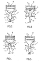
- the insulating part 11 is advantageously mounted movably between a first position (illustrated on the figure 2 ) in which it allows the free operation of the protective device 1, and in particular the formation of an electric arc 15 in the inter-electrode space 4, more precisely in the priming zone 40, and a second position (illustrated on the figure 3 ) in which it increases the isolation distance between the electrodes 2, 3, thus preventing the maintenance or rebooting of the electric arc, and ensuring simultaneously the final disconnection of the protective device 1 vis-à-vis the electrical installation.
- the insulating part 11 is mounted mobile in translation between its first and second positions, under the constraint of an actuating means, and preferably under the constraint of an elastic return means 12 of the spring type.
- the electrodes 2, 3 comprise parallel branches 2A, 3A spaced apart from one another and forming a slideway 13 in which the insulating part 11 is slidable under the stress exerted by the elastic return means 12.
- the second position of the insulating part 11 may advantageously be defined by a stop member B against the displacement thereof.
- said abutment B may be located, at least partially, within the inter-electrode space 4, so that the insulating part 11, after having been released, continues its race until it meets said abutment B in said inter-electrode space 4.
- the insulating part 11 is advantageously maintained by the detection means 8, which are for example formed by a fuse element 14, fixed relative to the housing 7 and for example secured to the latter.
- the fuse element 14 is preferably located near and preferably in physical contact with the insulating part 11, so as to detect, by conduction, the heating of the latter.
- the fuse element 14 is preferably formed by a calibrated tin-lead alloy to break or melt beyond the usual operating temperatures of the spark gap.
- the fuse element 14 is advantageously electrically isolated from the electrodes 2, 3, for example by interposition of a dielectric material.
- the detection means 8 are preferably mounted within the protective device 1 so as to release the disconnection means 9, and in particular the insulating means 10 (for example the insulating part 11) when a malfunction of the spark gap is detected.
- the insulating means 10, in particular the insulating part 11, are held directly or indirectly by the fuse element 14, such that the melting or breaking of the latter causes the release of the insulating means 10.
- the element fuse 14 and the insulating means 10 are thus advantageously mounted relative to each other so that the fuse element 14 forms a stop against the displacement of the insulating means 10 under the action of the restoring force F exerted by the elastic return means 12.
- the restoring force F exerted by the elastic return means 12 is directed towards the inter-electrode space 4, so as to push the insulating part 11 deeper inside the inter-electrode space 4 when a spark gap failure is detected.
- the insulating part 11 can form, in its first position, an insulating initiation aid to control the initiation of the electric arc 15 between the electrodes 2, 3.
- the insulating part 11 then allows better to control the level of protection of protection device 1 compared to devices without a booster auxiliary.
- an overvoltage greater than the trigger threshold of the spark gap occurs, an electric arc 15 is initiated between the electrodes 2, 3, along the surface S of the insulating piece 11 located at the interface with the gas.
- the insulating element 11 and the priming aid may be arranged superimposed between the parallel branches 2A, 3A, electrodes 2, 3.
- the priming aid is preferably fixed and the insulating part 11 is mobile. so as to be able to assume its function of isolation of the protective device 1.
- the insulating part 11 and the priming aid are preferably formed by an insulating material such as ceramic.
- the protective device 1 advantageously comprises an insulating ignition aid 16 which, in the operative position, is arranged between the electrodes 2, 3 so as to better control and control the initiation of an electric arc 15 between the electrodes.
- the electric arc 15 is then formed in the air, along the surface S 'of the priming aid 16.
- the priming aid 16 is advantageously mounted movably between its functional position (illustrated in FIG. figure 4 ) and a withdrawal position (shown on the figure 5 ) in which it is located outside the inter-electrode space 4.
- a current significant short circuit flows between the electrodes 2, 3, along the ignition auxiliary 16, which has the effect of significantly increasing the temperature of the spark gap, and therefore, by conduction, that of the ignition aid 16.
- the elastic return means 12 ' is designed to exert a restoring force F' directed in the direction opposite to the inter-electrode space 4 so as to ensure the withdrawal of the priming aid 16.
- the means of resilient return 12 'is thus designed to move from an extension configuration, illustrated on the figure 4 , to a rest configuration illustrated on the figure 5 .
- the insulating means 10 are advantageously formed by a gas, and for example by the air G located inside the housing 7 and able to be substituted, in the inter-electrode space 4, for the ignition aid 16 when the latter comes into its position of withdrawal illustrated on the figure 5 .
- the used priming aid 16 and the conductive deposit 18 are removed simultaneously from the inter-electrode space 4, and replaced by the gas.
- the gas, whose insulating capacity is greater (lower dielectric constant) than the priming aid 16, thus effectively ensures the isolation of the electrodes 2, 3 relative to each other.
- the protective device 1 may advantageously comprise indicating means (not shown) of the state of the spark gap.
- These indication means are advantageously functionally connected to the detection means, and preferably mechanically connected, directly or indirectly, to the insulating piece 11 or to the triggering aid 16.
- the indication means can be formed by a separate piece of the insulating part 11 or the triggering auxiliary 16, capable of moving opposite a window in the housing 7, when a failure of the spark gap is detected. It is also conceivable to provide a protection device 1 in which the indication means and the insulating part 11 (or the priming aid 16) are formed by one and the same piece.
- the protective device 1 advantageously comprises a breaking chamber 20, formed by an arrangement of metal splitting plates 21 located at the end of the inter-electrode space. 4 opposite to the priming zone 40.
- the interrupting chamber 20 thus ensures the cutting of the electric arc into a plurality of elementary arcs, so as to allow its extinction.
- the electric arc 15, initially formed in the priming zone 40 propagates, thanks to the V shape of the electrodes 2, 3, to the interrupting chamber 20 where it goes out.
- the displacement of the latter inside the inter-electrode space 4 in the direction of of the breaking chamber 20, has the effect of causing an elongation of the electric arc 15 and to drive the latter to the breaking chamber 20, thus accelerating its extinction.
- the breaking chamber 20 will be arranged, at least partially, on the path of the insulating part 11, so that the latter will stop when its end comes into contact with said breaking chamber 20, for example at a or several fractionating plates 21.
- the interrupting chamber 20 will preferably form the abutment B which defines the second position of the insulating part 11.
- the present invention also relates to a method of electrical insulation of a protection device 1 of an electrical installation against overvoltages comprising at least two electrodes 2, 3 delimiting an inter-electrode gap 4 forming a spark gap.
- the method comprises a step (a) for detecting a malfunction of the spark gap, followed, if a failure is detected, with a step (b) of disconnection of the spark gap vis-à-vis the electrical installation.
- the step (a) of detection comprises a phase of detection of the heating of the spark gap.
- the step (b) of disconnection advantageously comprises a phase of interposition of insulating means 10 between the electrodes 2, 3 of the protection device 1 so as to increase the isolation between the latter, thus ensuring the electrical isolation the protection device 1 vis-à-vis the electrical installation.
- the interposition phase advantageously comprises a phase of increasing the isolation distance between the electrodes 2, 3 with the aid of an insulating part 11.
- the interposition phase comprises a phase of displacement of the insulating part 11 in the inter-electrode space 4.
- a variant of this method which can be implemented when the protection device 1 comprises an insulating initiation aid 16, arranged between the electrodes 2, 3, consists in carrying out, during the interposition phase, a substitution of the ignition auxiliary 16 by a gas, in particular air, the gas then forming the insulating means 10.
- the isolation method according to the invention further comprises a step (c) of indicating to a third party, for example to an operator, that the protective device 1 is faulty and that it is necessary to make his change.
- the insulating part 11, respectively the priming aid 16 are arranged to allow the initiation of an electric arc 15 along the surface S, S 'between the electrodes 2, 3.
- the electric arc 15 then allows to flow, for example to earth, the current generated by the overvoltage.
- This electric arc 15 can lead, gradually or rapidly, depending on the intensity and duration of the voltage disturbances, to an erosion of the surface of the electrodes 2, 3, thus causing the formation of a conductive pollution in the internal space.
- This conductive pollution is reflected in particular by the formation of a conductive deposit 18 on the surface S or S '. In this case, there is conduction of a large current along the conductive deposit 18, resulting in excessive heating of the spark gap and the insulating part 11 (respectively of the priming aid 16).
- This excessive heating is then transmitted, for example by conduction, to the fuse element 14 which, when the temperature exceeds a predetermined critical value, begins to melt (or to break).
- the fusion (or rupture) of the fuse element 14 then releases the insulating means 10, for example the insulating part 11 or the gas, which then penetrate inside the inter-electrode space 4, interposing between the electrodes 2, 3 so as to increase the isolation, and for example the isolation distance, between them.
- the electric arc 15 elongates, then is driven to the interrupting chamber 20 where it extinguishes. Since the energy required for the formation of a new electric arc is particularly high because of the large isolation distance between the electrodes 2, 3, the protection device 1 is then isolated, so that effective and definitive, of the electrical installation.
- the invention therefore ensures, in the event of failure of the spark gap, a quick and reliable disconnection of the protection device 1 vis-à-vis the electrical installation, without disturbing the latter.
- protection device 1 can be in the form of an interchangeable cartridge, thus facilitating its handling by a non-expert user.
- Another advantage of the protective device 1 according to the invention is that it is not resettable and therefore constitutes a safer device than the devices of the prior art.
- the protection device 1 according to the invention also makes it possible to immediately report to the user any malfunction, thus enabling its rapid replacement.
- the invention finds its industrial application in the manufacture of devices for protecting electrical installations against overvoltages.
Landscapes
- Emergency Protection Circuit Devices (AREA)
- Cable Accessories (AREA)
- Thermistors And Varistors (AREA)
Claims (25)
- Schutzvorrichtung gegen insbesondere durch Blitzschlag bedingte Überspannungen, die dafür bestimmt ist, an eine Elektroinstallation angeschlossen zu werden, welche wenigstens zwei Elektroden (2, 3) umfasst, die einen einen Entlader bildenden Zwischenelektrodenraum (4) begrenzen, so wie:- Erfassungsmittel (8), die gegenüber dem Zustand des Entladers empfindlich sind und geeignet sind eine Funktionsstörung des letzteren zu erfassen, und- Mittel zum Abtrennen (9), die in Abhängigkeit von den Erfassungsmitteln (8) geeignet sind die Isolierung der Schutzvorrichtung (1) gegenüber der Elektroinstallation sicherzustellen, wenn ein Störfall des Entladers von den Erfassungsmitteln (8) erfasst wird, dadurch gekennzeichnet, dass die Mittel zum Abtrennen (9) von Isoliermitteln (10) gebildet werden, die geeignet sind in Abhängigkeit von den Erfassungsmitteln (8) zwischen den Elektroden (2, 3) positioniert zu werden, mit dem Ziel die Isolierung letzterer zu erhöhen.
- Vorrichtung nach Anspruch 1, dadurch gekennzeichnet, dass die Erfassungsmittel (8) gegenüber einer Erwärmung des Entladers empfindlich sind.
- Vorrichtung nach Anspruch 1 oder 2, dadurch gekennzeichnet, dass die Isoliermittel (10) von einem beweglichen Isolierstück (11) gebildet werden, das geeignet ist zwischen den Elektroden (2, 3) in der Art verschoben zu werden, dass die Trennstrecke zwischen letzteren erhöht wird.
- Vorrichtung nach Anspruch 3, dadurch gekennzeichnet, dass das Isolierstück (11) beweglich zwischen einer ersten Position angebracht ist, in der der ungehinderte Betrieb der Schutzvorrichtung (1) zugelassen wird, und einer zweiten Position, in der es die Trennstrecke zwischen den Elektroden (2, 3) erhöht, was folglich die Abtrennung der Schutzvorrichtung (1) von der Elektroinstallation sicherstellt.
- Vorrichtung nach Anspruch 4, dadurch gekennzeichnet, dass das Isolierstück (11) beweglich in der Verschiebung zwischen seiner ersten und seiner zweiten Position angebracht ist, zum Beispiel unter der Spannung eines Mittels für die elastische Rückstellung (12).
- Vorrichtung nach einem der Ansprüche 3 bis 5, dadurch gekennzeichnet, dass das Isolierstück (11) von den Erfassungsmitteln (8) in seiner ersten Position gehalten wird.
- Vorrichtung nach einem der vorhergehenden Ansprüche, dadurch gekennzeichnet, dass sie ein isolierendes Zündungshilfsmittel (16) umfasst, das in der funktionellen Position zwischen den Elektroden (2, 3) in der Art angeordnet ist, dass es die Zündung eines Lichtbogens (15) zwischen den Elektroden (2, 3) beherrscht.
- Vorrichtung nach den Ansprüchen 3 und 7, dadurch gekennzeichnet, dass das Isolierstück (11) von dem Zündungshilfsmittel (16) gebildet wird.
- Vorrichtung nach Anspruch 7, dadurch gekennzeichnet, dass das Zündungshilfsmittel (16) beweglich zwischen seiner funktionellen Position und einer Rückzugsposition angebracht ist, in welcher es sich außerhalb des Zwischenelektrodenraums (4) befindet.
- Vorrichtung nach Anspruch 9, dadurch gekennzeichnet, dass die Isoliermittel (10) von einem Gas gebildet werden, zum Beispiel von Luft, das geeignet ist das Zündungshilfsmittel (16) in dem Zwischenelektrodenraum (4) zu ersetzen, wenn letzteres in seine Rückzugsposition kommt.
- Vorrichtung nach Anspruch 1, dadurch gekennzeichnet, dass die Erfassungsmittel (8) inmitten der Schutzvorrichtung (1) in der Art angebracht sind, dass sie die Isoliermittel (10) freisetzen, wenn eine Funktionsstörung des Entladers erfasst wird.
- Vorrichtung nach einem der vorhergehenden Ansprüche, dadurch gekennzeichnet, dass die Erfassungsmittel (8) von einem schmelzbaren Element (14) gebildet werden.
- Vorrichtung nach einem der Ansprüche 1 bis 12, dadurch gekennzeichnet, dass die Isoliermittel (10) direkt oder indirekt von dem schmelzbaren Element (14) gehalten werden, so dass das Schmelzen oder das Brechen des schmelzbaren Elements (14) die Freisetzung der Isoliermittel (10) hervorruft.
- Vorrichtung nach Anspruch 2 und einem der Ansprüche 3 oder 7, dadurch gekennzeichnet, dass sich die Erfassungsmittel (8) in der Nähe des Isolierstücks (11) und/oder des Zündungshilfsmittels (16) in der Art befinden, dass sie eine Erwärmung letzterer erfassen.
- Vorrichtung nach einem der vorhergehenden Ansprüche, dadurch gekennzeichnet, dass sie Mittel zum Anzeigen des Zustands des Entladers umfasst.
- Vorrichtung nach Anspruch 15, dadurch gekennzeichnet, dass die Mittel zum Anzeigen funktionell mit den Erfassungsmitteln (8) verbunden sind.
- Vorrichtung nach den Ansprüchen 3 und 16, dadurch gekennzeichnet, dass die Mittel zum Anzeigen mechanisch mit dem Isolierstück (11) verbunden sind.
- Vorrichtung nach einem der Ansprüche 4 oder 5, dadurch gekennzeichnet, dass die zweite Position des Isolierstücks (11) von einem Element definiert wird, dass einen Anschlag (B) gegen eine Verschiebung desselben bildet.
- Vorrichtung nach Anspruch 18, dadurch gekennzeichnet, dass sie eine Funkenkammer (20) umfasst und dass die Funkenkammer den Anschlag (B) bildet, der die zweite Position des Isolierstücks (11) definiert.
- Verfahren des elektrischen Isolierens einer Schutzvorrichtung (1) gegen Überspannungen, die dafür bestimmt ist an einer Elektroinstallation angeschlossen zu werden, und die wenigstens zwei Elektroden (2, 3) umfasst, die einen einen Entlader bildenden Zwischenelektrodenraum (4) begrenzen, wobei das Verfahren nacheinander folgendes umfasst:- einen Schritt (a), in dem eine Funktionsstörung des Entladers erfasst wird,- einen Schritt (b), in dem der Entlader von der Elektroinstallation abgetrennt wird, wenn ein Störfall im Lauf des Schritts (a) erfasst wird,dadurch gekennzeichnet, dass der Schritt des Abtrennens (b) eine Phase des Einführens der Isoliermittel (10) zwischen die Elektroden der Schutzvorrichtung (1) in der Art umfasst, dass die Isolierung zwischen letzteren erhöht wird, was daher die elektrische Isolierung der Schutzvorrichtung (1) gegenüber der Elektroinstallation sicherstellt.
- Verfahren nach Anspruch 20, dadurch gekennzeichnet, dass der Schritt des Erfassens (a) eine Phase umfasst, in der eine Erwärmung des Entladers erfasst wird.
- Verfahren nach Anspruch 20, dadurch gekennzeichnet, dass die Phase des Einführens eine Phase der Erhöhung der Trennstrecke zwischen den Elektroden (2, 3) umfasst.
- Verfahren nach Anspruch 20, dadurch gekennzeichnet, dass die Phase des Einführens eine Phase der Verschiebung des Isolierstücks (11) in dem Zwischenelektrodenraum (4) umfasst, um die Trennstrecke zwischen den Elektroden (2, 3) zu erhöhen.
- Verfahren nach Anspruch 20, dadurch gekennzeichnet, dass die Schutzvorrichtung (1) ein isolierendes Zündungshilfsmittel (16) umfasst, das zwischen den Elektroden (2, 3) angeordnet ist, und dass die Phase des Einführens eine Phase des Ersetzens des Zündungshilfsmittels (16) durch ein Gas, zum Beispiel Luft, umfasst, wobei das Gas dann die Isoliermittel (10) bildet.
- Verfahren nach einem der Ansprüche 20 bis 24, dadurch gekennzeichnet, dass es einen dritten Schritt des Anzeigens (c), dass die Schutzvorrichtung (1) gestört ist, umfasst.
Applications Claiming Priority (2)
| Application Number | Priority Date | Filing Date | Title |
|---|---|---|---|
| FR0411376A FR2877155B1 (fr) | 2004-10-25 | 2004-10-25 | Dispositif de protection contre les surtensions a deconnexion amelioree et procede correspondant |
| PCT/FR2005/002657 WO2006045947A1 (fr) | 2004-10-25 | 2005-10-25 | Dispositif de protection contre les surtensions a deconnexion amelioree et procede correspondant |
Publications (2)
| Publication Number | Publication Date |
|---|---|
| EP1829176A1 EP1829176A1 (de) | 2007-09-05 |
| EP1829176B1 true EP1829176B1 (de) | 2010-06-02 |
Family
ID=34950187
Family Applications (1)
| Application Number | Title | Priority Date | Filing Date |
|---|---|---|---|
| EP05814818A Not-in-force EP1829176B1 (de) | 2004-10-25 | 2005-10-25 | Überspannungs-schutzeinrichtung mit verbesserter trennung und entsprechendes verfahren |
Country Status (5)
| Country | Link |
|---|---|
| EP (1) | EP1829176B1 (de) |
| AT (1) | ATE470255T1 (de) |
| DE (1) | DE602005021693D1 (de) |
| FR (1) | FR2877155B1 (de) |
| WO (1) | WO2006045947A1 (de) |
Cited By (1)
| Publication number | Priority date | Publication date | Assignee | Title |
|---|---|---|---|---|
| WO2012016743A1 (de) | 2010-08-04 | 2012-02-09 | Dehn + Söhne Gmbh + Co. Kg | Hörnerfunkenstrecke mit deionkammer |
Families Citing this family (1)
| Publication number | Priority date | Publication date | Assignee | Title |
|---|---|---|---|---|
| DE102012112543A1 (de) | 2012-12-18 | 2014-06-18 | Epcos Ag | Funkenstreckenanordnung und Verfahren zur Sicherung einer Funkenstreckenanordnung |
Family Cites Families (4)
| Publication number | Priority date | Publication date | Assignee | Title |
|---|---|---|---|---|
| DE554319C (de) * | 1932-07-06 | Emag Elek Zitaets Akt Ges | Loeschfunkenableiter mit Schutzschalter | |
| CH79255A (de) * | 1918-05-07 | 1918-10-16 | Oerlikon Maschf | Schutzvorrichtung gegen Überspannungen in elektrischen Anlagen |
| JP2570182B2 (ja) * | 1994-06-30 | 1997-01-08 | 日本電気株式会社 | 直流電源用避雷管 |
| US6430019B1 (en) * | 1998-06-08 | 2002-08-06 | Ferraz S.A. | Circuit protection device |
-
2004
- 2004-10-25 FR FR0411376A patent/FR2877155B1/fr not_active Expired - Fee Related
-
2005
- 2005-10-25 AT AT05814818T patent/ATE470255T1/de not_active IP Right Cessation
- 2005-10-25 EP EP05814818A patent/EP1829176B1/de not_active Not-in-force
- 2005-10-25 DE DE602005021693T patent/DE602005021693D1/de active Active
- 2005-10-25 WO PCT/FR2005/002657 patent/WO2006045947A1/fr active Application Filing
Cited By (6)
| Publication number | Priority date | Publication date | Assignee | Title |
|---|---|---|---|---|
| WO2012016743A1 (de) | 2010-08-04 | 2012-02-09 | Dehn + Söhne Gmbh + Co. Kg | Hörnerfunkenstrecke mit deionkammer |
| DE102011102257A1 (de) | 2010-08-04 | 2012-02-09 | Dehn + Söhne Gmbh + Co. Kg | Hörnerfunkenstrecke mit Deionkammer |
| CN103069672A (zh) * | 2010-08-04 | 2013-04-24 | 德恩及索恩两合股份有限公司 | 具有消电离室的角形火花隙 |
| CN103069672B (zh) * | 2010-08-04 | 2014-07-09 | 德恩及索恩两合股份有限公司 | 具有消电离室的角形火花隙 |
| DE102011102257B4 (de) * | 2010-08-04 | 2016-05-19 | Dehn + Söhne Gmbh + Co. Kg | Hörnerfunkenstrecke mit Deionkammer |
| DE102011123020B3 (de) * | 2010-08-04 | 2016-10-27 | Dehn + Söhne Gmbh + Co. Kg | Hörnerfunkenstrecke mit Deionkammer |
Also Published As
| Publication number | Publication date |
|---|---|
| DE602005021693D1 (de) | 2010-07-15 |
| FR2877155A1 (fr) | 2006-04-28 |
| FR2877155B1 (fr) | 2008-09-26 |
| EP1829176A1 (de) | 2007-09-05 |
| ATE470255T1 (de) | 2010-06-15 |
| WO2006045947A1 (fr) | 2006-05-04 |
Similar Documents
| Publication | Publication Date | Title |
|---|---|---|
| EP2375426B1 (de) | Varistor, der eine Elektrode mit einem vorstehenden Teil umfasst, der einen Kontakt bildet und Blitzableiter, der einen solchen Varistor umfasst | |
| EP2375425B1 (de) | Schutzvorrichtung gegen vorübergehende überlastspannung mit verbessertem thermoabschalter | |
| EP3459100B1 (de) | Schaltervorrichtung zur verbindung mit einem elektrischen stromkreis | |
| EP1743346B1 (de) | Überspannungsschutzeinrichtung mit lichtbogenlöschelementen | |
| EP1447831B1 (de) | Schutzvorrichtung gegen Blitzüberspannungen | |
| EP3991191B1 (de) | Elektrischer schutzschalter | |
| FR2848353A1 (fr) | Dispositif de protection contre des surtensions | |
| FR3023988A3 (de) | ||
| EP2513942A1 (de) | Anordnung für den schutz vor stromstössen | |
| EP1815569B1 (de) | Überspannungsschutzeinrichtung mit verbesserter trennung | |
| EP1102371A1 (de) | Blitzableitervorrichtung für Niederspannungsnetz | |
| EP1829176B1 (de) | Überspannungs-schutzeinrichtung mit verbesserter trennung und entsprechendes verfahren | |
| WO2006072737A2 (fr) | Appareil de protection d'une installation electrique a capacite de coupure amelioree | |
| EP1803137B1 (de) | Überspannungsschutzeinrichtung mit bogenschneidmitteln und entsprechendes verfahren | |
| EP1953788B1 (de) | Vorrichtung zum Schutz gegen Überspannungen mit beweglicher Elektrode und Entriegelungssystem der Verbindungsunterbrechungsvorrichtung | |
| EP0064016B1 (de) | Schutzsystem gegen Spannungsvorkommen an metallischen Strukturen | |
| WO2006059011A1 (fr) | Dispositif de protection d’une installation electrique, procede et utilisation correspondants | |
| EP1961087B1 (de) | Vorrichtung für den schutz gegen überspannungen mit verbesserter sicherheit und zugehöriges herstellungsverfahren | |
| EP0027061A1 (de) | Blitzableitervorrichtung, welche ein äusserliches Kurzschliessen erlaubt, und entsprechende Schutzeinheit | |
| EP1698029B1 (de) | Überspannungsschutzvorrichtung mit klemmanordnung | |
| FR2484695A1 (fr) | Parafoudre permettant une mise en court-circuit exterieure |
Legal Events
| Date | Code | Title | Description |
|---|---|---|---|
| PUAI | Public reference made under article 153(3) epc to a published international application that has entered the european phase |
Free format text: ORIGINAL CODE: 0009012 |
|
| 17P | Request for examination filed |
Effective date: 20070518 |
|
| AK | Designated contracting states |
Kind code of ref document: A1 Designated state(s): AT BE BG CH CY CZ DE DK EE ES FI FR GB GR HU IE IS IT LI LT LU LV MC NL PL PT RO SE SI SK TR |
|
| RIN1 | Information on inventor provided before grant (corrected) |
Inventor name: LINDEPERG, HERVE Inventor name: MAURICE, LOUIS, BERNARD, CLAUDE Inventor name: SERRIE, GERARD |
|
| DAX | Request for extension of the european patent (deleted) | ||
| GRAP | Despatch of communication of intention to grant a patent |
Free format text: ORIGINAL CODE: EPIDOSNIGR1 |
|
| GRAS | Grant fee paid |
Free format text: ORIGINAL CODE: EPIDOSNIGR3 |
|
| GRAA | (expected) grant |
Free format text: ORIGINAL CODE: 0009210 |
|
| AK | Designated contracting states |
Kind code of ref document: B1 Designated state(s): AT BE BG CH CY CZ DE DK EE ES FI FR GB GR HU IE IS IT LI LT LU LV MC NL PL PT RO SE SI SK TR |
|
| REG | Reference to a national code |
Ref country code: GB Ref legal event code: FG4D Free format text: NOT ENGLISH |
|
| REG | Reference to a national code |
Ref country code: CH Ref legal event code: EP |
|
| REG | Reference to a national code |
Ref country code: IE Ref legal event code: FG4D Free format text: LANGUAGE OF EP DOCUMENT: FRENCH |
|
| REF | Corresponds to: |
Ref document number: 602005021693 Country of ref document: DE Date of ref document: 20100715 Kind code of ref document: P |
|
| REG | Reference to a national code |
Ref country code: NL Ref legal event code: VDEP Effective date: 20100602 |
|
| PG25 | Lapsed in a contracting state [announced via postgrant information from national office to epo] |
Ref country code: SE Free format text: LAPSE BECAUSE OF FAILURE TO SUBMIT A TRANSLATION OF THE DESCRIPTION OR TO PAY THE FEE WITHIN THE PRESCRIBED TIME-LIMIT Effective date: 20100602 Ref country code: LT Free format text: LAPSE BECAUSE OF FAILURE TO SUBMIT A TRANSLATION OF THE DESCRIPTION OR TO PAY THE FEE WITHIN THE PRESCRIBED TIME-LIMIT Effective date: 20100602 |
|
| LTIE | Lt: invalidation of european patent or patent extension |
Effective date: 20100602 |
|
| PG25 | Lapsed in a contracting state [announced via postgrant information from national office to epo] |
Ref country code: AT Free format text: LAPSE BECAUSE OF FAILURE TO SUBMIT A TRANSLATION OF THE DESCRIPTION OR TO PAY THE FEE WITHIN THE PRESCRIBED TIME-LIMIT Effective date: 20100602 Ref country code: SI Free format text: LAPSE BECAUSE OF FAILURE TO SUBMIT A TRANSLATION OF THE DESCRIPTION OR TO PAY THE FEE WITHIN THE PRESCRIBED TIME-LIMIT Effective date: 20100602 Ref country code: LV Free format text: LAPSE BECAUSE OF FAILURE TO SUBMIT A TRANSLATION OF THE DESCRIPTION OR TO PAY THE FEE WITHIN THE PRESCRIBED TIME-LIMIT Effective date: 20100602 Ref country code: FI Free format text: LAPSE BECAUSE OF FAILURE TO SUBMIT A TRANSLATION OF THE DESCRIPTION OR TO PAY THE FEE WITHIN THE PRESCRIBED TIME-LIMIT Effective date: 20100602 |
|
| PG25 | Lapsed in a contracting state [announced via postgrant information from national office to epo] |
Ref country code: GR Free format text: LAPSE BECAUSE OF FAILURE TO SUBMIT A TRANSLATION OF THE DESCRIPTION OR TO PAY THE FEE WITHIN THE PRESCRIBED TIME-LIMIT Effective date: 20100903 Ref country code: CY Free format text: LAPSE BECAUSE OF FAILURE TO SUBMIT A TRANSLATION OF THE DESCRIPTION OR TO PAY THE FEE WITHIN THE PRESCRIBED TIME-LIMIT Effective date: 20100602 Ref country code: PL Free format text: LAPSE BECAUSE OF FAILURE TO SUBMIT A TRANSLATION OF THE DESCRIPTION OR TO PAY THE FEE WITHIN THE PRESCRIBED TIME-LIMIT Effective date: 20100602 |
|
| REG | Reference to a national code |
Ref country code: IE Ref legal event code: FD4D |
|
| PG25 | Lapsed in a contracting state [announced via postgrant information from national office to epo] |
Ref country code: NL Free format text: LAPSE BECAUSE OF FAILURE TO SUBMIT A TRANSLATION OF THE DESCRIPTION OR TO PAY THE FEE WITHIN THE PRESCRIBED TIME-LIMIT Effective date: 20100602 Ref country code: EE Free format text: LAPSE BECAUSE OF FAILURE TO SUBMIT A TRANSLATION OF THE DESCRIPTION OR TO PAY THE FEE WITHIN THE PRESCRIBED TIME-LIMIT Effective date: 20100602 Ref country code: IE Free format text: LAPSE BECAUSE OF FAILURE TO SUBMIT A TRANSLATION OF THE DESCRIPTION OR TO PAY THE FEE WITHIN THE PRESCRIBED TIME-LIMIT Effective date: 20100602 |
|
| PG25 | Lapsed in a contracting state [announced via postgrant information from national office to epo] |
Ref country code: IS Free format text: LAPSE BECAUSE OF FAILURE TO SUBMIT A TRANSLATION OF THE DESCRIPTION OR TO PAY THE FEE WITHIN THE PRESCRIBED TIME-LIMIT Effective date: 20101002 Ref country code: PT Free format text: LAPSE BECAUSE OF FAILURE TO SUBMIT A TRANSLATION OF THE DESCRIPTION OR TO PAY THE FEE WITHIN THE PRESCRIBED TIME-LIMIT Effective date: 20101004 Ref country code: RO Free format text: LAPSE BECAUSE OF FAILURE TO SUBMIT A TRANSLATION OF THE DESCRIPTION OR TO PAY THE FEE WITHIN THE PRESCRIBED TIME-LIMIT Effective date: 20100602 Ref country code: SK Free format text: LAPSE BECAUSE OF FAILURE TO SUBMIT A TRANSLATION OF THE DESCRIPTION OR TO PAY THE FEE WITHIN THE PRESCRIBED TIME-LIMIT Effective date: 20100602 Ref country code: CZ Free format text: LAPSE BECAUSE OF FAILURE TO SUBMIT A TRANSLATION OF THE DESCRIPTION OR TO PAY THE FEE WITHIN THE PRESCRIBED TIME-LIMIT Effective date: 20100602 |
|
| PLBE | No opposition filed within time limit |
Free format text: ORIGINAL CODE: 0009261 |
|
| STAA | Information on the status of an ep patent application or granted ep patent |
Free format text: STATUS: NO OPPOSITION FILED WITHIN TIME LIMIT |
|
| PG25 | Lapsed in a contracting state [announced via postgrant information from national office to epo] |
Ref country code: DK Free format text: LAPSE BECAUSE OF FAILURE TO SUBMIT A TRANSLATION OF THE DESCRIPTION OR TO PAY THE FEE WITHIN THE PRESCRIBED TIME-LIMIT Effective date: 20100602 |
|
| BERE | Be: lapsed |
Owner name: ABB FRANCE Effective date: 20101031 |
|
| 26N | No opposition filed |
Effective date: 20110303 |
|
| PG25 | Lapsed in a contracting state [announced via postgrant information from national office to epo] |
Ref country code: MC Free format text: LAPSE BECAUSE OF NON-PAYMENT OF DUE FEES Effective date: 20101031 |
|
| REG | Reference to a national code |
Ref country code: CH Ref legal event code: PL |
|
| REG | Reference to a national code |
Ref country code: DE Ref legal event code: R097 Ref document number: 602005021693 Country of ref document: DE Effective date: 20110302 |
|
| PG25 | Lapsed in a contracting state [announced via postgrant information from national office to epo] |
Ref country code: LI Free format text: LAPSE BECAUSE OF NON-PAYMENT OF DUE FEES Effective date: 20101031 Ref country code: CH Free format text: LAPSE BECAUSE OF NON-PAYMENT OF DUE FEES Effective date: 20101031 |
|
| PG25 | Lapsed in a contracting state [announced via postgrant information from national office to epo] |
Ref country code: BE Free format text: LAPSE BECAUSE OF NON-PAYMENT OF DUE FEES Effective date: 20101031 |
|
| PG25 | Lapsed in a contracting state [announced via postgrant information from national office to epo] |
Ref country code: HU Free format text: LAPSE BECAUSE OF FAILURE TO SUBMIT A TRANSLATION OF THE DESCRIPTION OR TO PAY THE FEE WITHIN THE PRESCRIBED TIME-LIMIT Effective date: 20101203 Ref country code: LU Free format text: LAPSE BECAUSE OF NON-PAYMENT OF DUE FEES Effective date: 20101025 Ref country code: BG Free format text: LAPSE BECAUSE OF FAILURE TO SUBMIT A TRANSLATION OF THE DESCRIPTION OR TO PAY THE FEE WITHIN THE PRESCRIBED TIME-LIMIT Effective date: 20100602 |
|
| PG25 | Lapsed in a contracting state [announced via postgrant information from national office to epo] |
Ref country code: TR Free format text: LAPSE BECAUSE OF FAILURE TO SUBMIT A TRANSLATION OF THE DESCRIPTION OR TO PAY THE FEE WITHIN THE PRESCRIBED TIME-LIMIT Effective date: 20100602 |
|
| PG25 | Lapsed in a contracting state [announced via postgrant information from national office to epo] |
Ref country code: BG Free format text: LAPSE BECAUSE OF FAILURE TO SUBMIT A TRANSLATION OF THE DESCRIPTION OR TO PAY THE FEE WITHIN THE PRESCRIBED TIME-LIMIT Effective date: 20100902 |
|
| PG25 | Lapsed in a contracting state [announced via postgrant information from national office to epo] |
Ref country code: ES Free format text: LAPSE BECAUSE OF FAILURE TO SUBMIT A TRANSLATION OF THE DESCRIPTION OR TO PAY THE FEE WITHIN THE PRESCRIBED TIME-LIMIT Effective date: 20100913 |
|
| REG | Reference to a national code |
Ref country code: DE Ref legal event code: R082 Ref document number: 602005021693 Country of ref document: DE Representative=s name: KUHNEN & WACKER PATENT- UND RECHTSANWALTSBUERO, DE |
|
| REG | Reference to a national code |
Ref country code: DE Ref legal event code: R081 Ref document number: 602005021693 Country of ref document: DE Owner name: ABB FRANCE, FR Free format text: FORMER OWNER: ABB FRANCE, RUEIL-MALMAISON, FR Effective date: 20140331 Ref country code: DE Ref legal event code: R082 Ref document number: 602005021693 Country of ref document: DE Representative=s name: KUHNEN & WACKER PATENT- UND RECHTSANWALTSBUERO, DE Effective date: 20140331 |
|
| PGFP | Annual fee paid to national office [announced via postgrant information from national office to epo] |
Ref country code: DE Payment date: 20141022 Year of fee payment: 10 Ref country code: GB Payment date: 20141021 Year of fee payment: 10 Ref country code: FR Payment date: 20141022 Year of fee payment: 10 |
|
| PGFP | Annual fee paid to national office [announced via postgrant information from national office to epo] |
Ref country code: IT Payment date: 20141027 Year of fee payment: 10 |
|
| REG | Reference to a national code |
Ref country code: DE Ref legal event code: R119 Ref document number: 602005021693 Country of ref document: DE |
|
| GBPC | Gb: european patent ceased through non-payment of renewal fee |
Effective date: 20151025 |
|
| PG25 | Lapsed in a contracting state [announced via postgrant information from national office to epo] |
Ref country code: DE Free format text: LAPSE BECAUSE OF NON-PAYMENT OF DUE FEES Effective date: 20160503 Ref country code: GB Free format text: LAPSE BECAUSE OF NON-PAYMENT OF DUE FEES Effective date: 20151025 Ref country code: IT Free format text: LAPSE BECAUSE OF NON-PAYMENT OF DUE FEES Effective date: 20151025 |
|
| REG | Reference to a national code |
Ref country code: FR Ref legal event code: ST Effective date: 20160630 |
|
| PG25 | Lapsed in a contracting state [announced via postgrant information from national office to epo] |
Ref country code: FR Free format text: LAPSE BECAUSE OF NON-PAYMENT OF DUE FEES Effective date: 20151102 |