EP1829176B1 - Improved-disconnection overvoltage protection device and corresponding method - Google Patents
Improved-disconnection overvoltage protection device and corresponding method Download PDFInfo
- Publication number
- EP1829176B1 EP1829176B1 EP05814818A EP05814818A EP1829176B1 EP 1829176 B1 EP1829176 B1 EP 1829176B1 EP 05814818 A EP05814818 A EP 05814818A EP 05814818 A EP05814818 A EP 05814818A EP 1829176 B1 EP1829176 B1 EP 1829176B1
- Authority
- EP
- European Patent Office
- Prior art keywords
- isolating
- electrodes
- spark gap
- protection device
- detection means
- Prior art date
- Legal status (The legal status is an assumption and is not a legal conclusion. Google has not performed a legal analysis and makes no representation as to the accuracy of the status listed.)
- Not-in-force
Links
Images

Classifications
-
- H—ELECTRICITY
- H01—ELECTRIC ELEMENTS
- H01T—SPARK GAPS; OVERVOLTAGE ARRESTERS USING SPARK GAPS; SPARKING PLUGS; CORONA DEVICES; GENERATING IONS TO BE INTRODUCED INTO NON-ENCLOSED GASES
- H01T1/00—Details of spark gaps
- H01T1/12—Means structurally associated with spark gap for recording operation thereof
-
- H—ELECTRICITY
- H01—ELECTRIC ELEMENTS
- H01T—SPARK GAPS; OVERVOLTAGE ARRESTERS USING SPARK GAPS; SPARKING PLUGS; CORONA DEVICES; GENERATING IONS TO BE INTRODUCED INTO NON-ENCLOSED GASES
- H01T1/00—Details of spark gaps
- H01T1/14—Means structurally associated with spark gap for protecting it against overload or for disconnecting it in case of failure
Definitions
- the present invention relates to the general technical field of equipment protection devices or electrical installations against overvoltages, including transient overvoltages due to lightning.
- the present invention relates more particularly to a protection device against overvoltages due in particular to a lightning strike intended to be connected to an electrical installation and comprising at least two electrodes defining an inter-electrode space forming a spark gap.
- the invention also relates to a method for electrically isolating a surge protection device intended to be connected to an electrical installation and comprising at least two electrodes delimiting an inter-electrode space forming a spark gap.
- a low-voltage protection device using the technology of spark gaps, such as spark gap arrester.
- This device is generally associated in series with a complementary external cut-off device, able to isolate the protection device against overvoltages of the electrical installation when a current of excessively high current passes through it.
- overcurrent protection devices such as circuit breakers. These devices thus make it possible to isolate the overvoltage protection device, while avoiding the opening of the other general breaking devices of the electrical installation, in order to ensure continuity of service of the power supply.
- the surge arrester and the circuit breaker are sometimes located at a distance from each other and the impedance of the connecting conductors is often difficult, if not impossible to calculate precisely, which can lead to errors and an underestimation of the actual level of protection of the electrical installation.
- the document DE-C-554 319 discloses an overvoltage protection device according to the preamble of claim 1 and a method of electrical isolation, according to the preamble of claim 20.
- the objects assigned to the invention therefore aim to propose a new device for protecting an electrical installation against overvoltages that do not have the drawbacks listed above and that, in the event of a failure, to be definitively disconnected from the electrical installation. .
- Another object of the invention is to propose a new device for protecting an electrical installation against overvoltages having a good reliability of disconnection.
- Another object of the invention is to propose a new device for protecting an electrical installation against overvoltages which is particularly easy to use, thus limiting the risk of error for the operator.
- Another object of the invention is to propose a new device for protecting an electrical installation against overvoltages having a compact, robust and inexpensive construction structure.
- Another object of the invention is to provide a new device for protecting an electrical installation against overvoltages whose manufacture requires only standard components, and which can be obtained easily without fundamentally modifying the overall structure of the protective devices. spark gap known.
- Another object of the invention is to propose a new device for protecting an electrical installation against overvoltages whose operating state can be easily monitored.
- the objects assigned to the invention are also intended to propose a new method of electrical insulation of a protection device of an electrical installation against overvoltages allowing, in a simple way and using standard components, to effectively isolate the device in case of failure of the latter.
- Another object of the invention is to propose a new method of electrical insulation of a protection device of an electrical installation against overvoltages allowing a close monitoring of the operating state of the device.
- the overvoltage protection device according to the invention is intended to be connected bypass (or parallel) on the equipment or electrical installation to be protected.
- electrical installation refers to any type of device or network that is susceptible to voltage disturbances, including transient overvoltages due to lightning.
- the overvoltage protection device according to the invention is advantageously intended to be disposed between a phase of the installation to be protected and the earth. It is also conceivable, without departing from the scope of the invention, that the protection device, instead of being connected bypass between a phase and the earth, is connected between the neutral and the earth, between the phase and neutral, or between two phases (case of a differential protection).
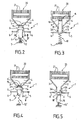
- FIG. 1 An exemplary embodiment of a protection device 1 according to the invention is illustrated on the figure 1 .
- the protection device 1 is advantageously in the form of a spark gap arrester.
- the protective device 1 thus comprises at least two electrodes, for example a first electrode 2 and a second electrode 3 delimiting an inter-electrode gap 4 forming a spark gap.
- the first and second electrodes 2, 3 can thus advantageously form the main electrodes of the spark gap.
- the protection device 1 according to the invention also advantageously comprises connecting branches 5, 6 to the electrical installation or to the power supply network, making it possible to electrically connect the protection device 1 to the electrical installation (not shown) to protect.
- the electrodes 2, 3 and the connecting branches 5, 6 can advantageously be formed by one and the same conductive part, for example metal. All of these elements is advantageously mounted within an insulating casing 7.
- the housing 7 may constitute a module (or cartridge) plug-in on a base, thereby facilitating the introduction or removal of the protective device 1 by the operator.
- the inter-electrode space 4 is filled, at least partially, with a gas, preferably with air so as to form a dielectric medium between the electrodes 2, 3.
- the inter-electrode space 4 form in this case an air gap.
- the protective device 1 is based on the technology of air gaps.
- the protective device 1 according to the invention uses encapsulated spark gap technology, the air then being replaced by a gas, for example a rare gas maintained under controlled pressure.
- Such spark gaps undergo, during their lifetime, degradation. This degradation can be gradual or abrupt, especially the spark gap is used intensively or repeatedly, with a high frequency. Several phenomena, specific to the gaps, can lead to this degradation of the protective device.
- an electric arc 15, corresponding to the ionization of the gas located in the inter-electrode space 4 is formed. between the electrodes 2, 3 and flows, for example to earth, the current corresponding to the overvoltage.
- the protective device 1 then deflects the current and allows to preserve the electrical installation.
- the electric arc can cause erosion of the electrodes 2, 3, tearing metal particles on the surface thereof. These metal particles are then likely to be deposited at another place in the inter-electrode space, thus creating a conductive pollution within the spark gap. This pollution can lead, when important, to a failure of the spark gap, several evolutions then being possible until the end of life of the spark gap.
- the metal particles can be deposited on the surface of the dielectric lamella, thus forming a conductive deposit between the electrodes.
- This conductive deposit gradually forms a metal bridge between the electrodes, short-circuiting the spark gap.
- a large short-circuit current can then flow, by conduction, to the surface of the dielectric lamella, thus causing significant heating of the spark gap.
- the protection device should be disconnected as soon as possible and replaced, since it is no longer able to properly protect the electrical installation.
- the end of life of the spark gap is random, so that it is particularly difficult, if not impossible, to predict in advance its replacement.
- the protection device 1 comprises detection means 8, sensitive to the state of the spark gap and able to detect a malfunction of this last.
- the detection means are designed to detect a possible failure of the behavior of the spark gap, resulting, for example, in a heating excessive of the latter.
- the detection means 8 are advantageously sensitive to excessive heating of the spark gap, which may occur when the spark gap is faulty.
- the detection means 8 are sensitive to the temperature, and are advantageously located near the spark gap to detect as soon as possible an abnormal heating of the latter, regardless of the heating of a possible circuit associated tripping electronics, or other breaking means, of the circuit breaker type, located near the protection device 1.
- the protective device 1 of the electrical installation should be disconnected as soon as possible and then replaced.
- the protection device 1 comprises disconnection means 9, able to ensure, under the control of the detection means 8, isolation of the device of the invention. protection 1 vis-à-vis the electrical installation when a failure of the spark gap is detected.
- the detection means 8 being directly sensitive to the state of heating of the spark gap, they are designed to trigger the disconnection means 9 when the temperature of the spark gap exceeds a predetermined threshold value.
- the isolation of the spark gap is immediate, which in particular limits the risk of fire.
- the disconnection means 9 are formed by movable insulating means 10 capable of coming, under the control of the detection means 8, that is to say when a failure of the spark gap is detected by these, position themselves between the electrodes 2, 3 to increase the isolation between them.
- the insulating means 10 are adapted to increase the electrical isolation capacitances of the inter-electrode space 4, and therefore the energy required for an electric arc to be formed between the electrodes 2, 3.
- the protection device 1 according to the invention also makes it possible to avoid using a complex additional cut-off device, such as a circuit breaker.
- the insulating means 10 are formed by an insulating piece 11 mounted movably within the housing 7 so as to be able to move between the electrodes 2, 3 in order to increase the isolation distance between the latter when a failure, and in particular a heating of the spark gap, is detected by the detection means 8.
- isolation distance here refers to the distance that the electric arc must travel to electrically connect the electrodes 2, 3. It exists, when the spark gap is operational, that is to say non-degraded , a so-called “functional " isolation distance, which corresponds substantially to the width of the inter-electrode gap 4 necessary for an electric arc to start when an overvoltage reaching or exceeding a predetermined threshold value occurs.
- the insulating part 11 is therefore advantageously designed to increase the isolation distance between the electrodes 2, 3, so that the latter exceeds the above-mentioned functional isolation distance.
- the protective device 1 is advantageously dimensioned so that this energy is never reached in the usual operating conditions of the spark gap, which ensures the electrical insulation of the latter.
- the width of the inter-electrode space is not necessarily constant and can vary along the electrodes 2, 3.
- the electrodes 2, 3 can advantageously have a V shape, the V hollow, which has the distance the weakest isolation, then advantageously forming the ignition zone 40 of the electric arc.
- the insulating part 11 is advantageously mounted movably between a first position (illustrated on the figure 2 ) in which it allows the free operation of the protective device 1, and in particular the formation of an electric arc 15 in the inter-electrode space 4, more precisely in the priming zone 40, and a second position (illustrated on the figure 3 ) in which it increases the isolation distance between the electrodes 2, 3, thus preventing the maintenance or rebooting of the electric arc, and ensuring simultaneously the final disconnection of the protective device 1 vis-à-vis the electrical installation.
- the insulating part 11 is mounted mobile in translation between its first and second positions, under the constraint of an actuating means, and preferably under the constraint of an elastic return means 12 of the spring type.
- the electrodes 2, 3 comprise parallel branches 2A, 3A spaced apart from one another and forming a slideway 13 in which the insulating part 11 is slidable under the stress exerted by the elastic return means 12.
- the second position of the insulating part 11 may advantageously be defined by a stop member B against the displacement thereof.
- said abutment B may be located, at least partially, within the inter-electrode space 4, so that the insulating part 11, after having been released, continues its race until it meets said abutment B in said inter-electrode space 4.
- the insulating part 11 is advantageously maintained by the detection means 8, which are for example formed by a fuse element 14, fixed relative to the housing 7 and for example secured to the latter.
- the fuse element 14 is preferably located near and preferably in physical contact with the insulating part 11, so as to detect, by conduction, the heating of the latter.
- the fuse element 14 is preferably formed by a calibrated tin-lead alloy to break or melt beyond the usual operating temperatures of the spark gap.
- the fuse element 14 is advantageously electrically isolated from the electrodes 2, 3, for example by interposition of a dielectric material.
- the detection means 8 are preferably mounted within the protective device 1 so as to release the disconnection means 9, and in particular the insulating means 10 (for example the insulating part 11) when a malfunction of the spark gap is detected.
- the insulating means 10, in particular the insulating part 11, are held directly or indirectly by the fuse element 14, such that the melting or breaking of the latter causes the release of the insulating means 10.
- the element fuse 14 and the insulating means 10 are thus advantageously mounted relative to each other so that the fuse element 14 forms a stop against the displacement of the insulating means 10 under the action of the restoring force F exerted by the elastic return means 12.
- the restoring force F exerted by the elastic return means 12 is directed towards the inter-electrode space 4, so as to push the insulating part 11 deeper inside the inter-electrode space 4 when a spark gap failure is detected.
- the insulating part 11 can form, in its first position, an insulating initiation aid to control the initiation of the electric arc 15 between the electrodes 2, 3.
- the insulating part 11 then allows better to control the level of protection of protection device 1 compared to devices without a booster auxiliary.
- an overvoltage greater than the trigger threshold of the spark gap occurs, an electric arc 15 is initiated between the electrodes 2, 3, along the surface S of the insulating piece 11 located at the interface with the gas.
- the insulating element 11 and the priming aid may be arranged superimposed between the parallel branches 2A, 3A, electrodes 2, 3.
- the priming aid is preferably fixed and the insulating part 11 is mobile. so as to be able to assume its function of isolation of the protective device 1.
- the insulating part 11 and the priming aid are preferably formed by an insulating material such as ceramic.
- the protective device 1 advantageously comprises an insulating ignition aid 16 which, in the operative position, is arranged between the electrodes 2, 3 so as to better control and control the initiation of an electric arc 15 between the electrodes.
- the electric arc 15 is then formed in the air, along the surface S 'of the priming aid 16.
- the priming aid 16 is advantageously mounted movably between its functional position (illustrated in FIG. figure 4 ) and a withdrawal position (shown on the figure 5 ) in which it is located outside the inter-electrode space 4.
- a current significant short circuit flows between the electrodes 2, 3, along the ignition auxiliary 16, which has the effect of significantly increasing the temperature of the spark gap, and therefore, by conduction, that of the ignition aid 16.
- the elastic return means 12 ' is designed to exert a restoring force F' directed in the direction opposite to the inter-electrode space 4 so as to ensure the withdrawal of the priming aid 16.
- the means of resilient return 12 'is thus designed to move from an extension configuration, illustrated on the figure 4 , to a rest configuration illustrated on the figure 5 .
- the insulating means 10 are advantageously formed by a gas, and for example by the air G located inside the housing 7 and able to be substituted, in the inter-electrode space 4, for the ignition aid 16 when the latter comes into its position of withdrawal illustrated on the figure 5 .
- the used priming aid 16 and the conductive deposit 18 are removed simultaneously from the inter-electrode space 4, and replaced by the gas.
- the gas, whose insulating capacity is greater (lower dielectric constant) than the priming aid 16, thus effectively ensures the isolation of the electrodes 2, 3 relative to each other.
- the protective device 1 may advantageously comprise indicating means (not shown) of the state of the spark gap.
- These indication means are advantageously functionally connected to the detection means, and preferably mechanically connected, directly or indirectly, to the insulating piece 11 or to the triggering aid 16.
- the indication means can be formed by a separate piece of the insulating part 11 or the triggering auxiliary 16, capable of moving opposite a window in the housing 7, when a failure of the spark gap is detected. It is also conceivable to provide a protection device 1 in which the indication means and the insulating part 11 (or the priming aid 16) are formed by one and the same piece.
- the protective device 1 advantageously comprises a breaking chamber 20, formed by an arrangement of metal splitting plates 21 located at the end of the inter-electrode space. 4 opposite to the priming zone 40.
- the interrupting chamber 20 thus ensures the cutting of the electric arc into a plurality of elementary arcs, so as to allow its extinction.
- the electric arc 15, initially formed in the priming zone 40 propagates, thanks to the V shape of the electrodes 2, 3, to the interrupting chamber 20 where it goes out.
- the displacement of the latter inside the inter-electrode space 4 in the direction of of the breaking chamber 20, has the effect of causing an elongation of the electric arc 15 and to drive the latter to the breaking chamber 20, thus accelerating its extinction.
- the breaking chamber 20 will be arranged, at least partially, on the path of the insulating part 11, so that the latter will stop when its end comes into contact with said breaking chamber 20, for example at a or several fractionating plates 21.
- the interrupting chamber 20 will preferably form the abutment B which defines the second position of the insulating part 11.
- the present invention also relates to a method of electrical insulation of a protection device 1 of an electrical installation against overvoltages comprising at least two electrodes 2, 3 delimiting an inter-electrode gap 4 forming a spark gap.
- the method comprises a step (a) for detecting a malfunction of the spark gap, followed, if a failure is detected, with a step (b) of disconnection of the spark gap vis-à-vis the electrical installation.
- the step (a) of detection comprises a phase of detection of the heating of the spark gap.
- the step (b) of disconnection advantageously comprises a phase of interposition of insulating means 10 between the electrodes 2, 3 of the protection device 1 so as to increase the isolation between the latter, thus ensuring the electrical isolation the protection device 1 vis-à-vis the electrical installation.
- the interposition phase advantageously comprises a phase of increasing the isolation distance between the electrodes 2, 3 with the aid of an insulating part 11.
- the interposition phase comprises a phase of displacement of the insulating part 11 in the inter-electrode space 4.
- a variant of this method which can be implemented when the protection device 1 comprises an insulating initiation aid 16, arranged between the electrodes 2, 3, consists in carrying out, during the interposition phase, a substitution of the ignition auxiliary 16 by a gas, in particular air, the gas then forming the insulating means 10.
- the isolation method according to the invention further comprises a step (c) of indicating to a third party, for example to an operator, that the protective device 1 is faulty and that it is necessary to make his change.
- the insulating part 11, respectively the priming aid 16 are arranged to allow the initiation of an electric arc 15 along the surface S, S 'between the electrodes 2, 3.
- the electric arc 15 then allows to flow, for example to earth, the current generated by the overvoltage.
- This electric arc 15 can lead, gradually or rapidly, depending on the intensity and duration of the voltage disturbances, to an erosion of the surface of the electrodes 2, 3, thus causing the formation of a conductive pollution in the internal space.
- This conductive pollution is reflected in particular by the formation of a conductive deposit 18 on the surface S or S '. In this case, there is conduction of a large current along the conductive deposit 18, resulting in excessive heating of the spark gap and the insulating part 11 (respectively of the priming aid 16).
- This excessive heating is then transmitted, for example by conduction, to the fuse element 14 which, when the temperature exceeds a predetermined critical value, begins to melt (or to break).
- the fusion (or rupture) of the fuse element 14 then releases the insulating means 10, for example the insulating part 11 or the gas, which then penetrate inside the inter-electrode space 4, interposing between the electrodes 2, 3 so as to increase the isolation, and for example the isolation distance, between them.
- the electric arc 15 elongates, then is driven to the interrupting chamber 20 where it extinguishes. Since the energy required for the formation of a new electric arc is particularly high because of the large isolation distance between the electrodes 2, 3, the protection device 1 is then isolated, so that effective and definitive, of the electrical installation.
- the invention therefore ensures, in the event of failure of the spark gap, a quick and reliable disconnection of the protection device 1 vis-à-vis the electrical installation, without disturbing the latter.
- protection device 1 can be in the form of an interchangeable cartridge, thus facilitating its handling by a non-expert user.
- Another advantage of the protective device 1 according to the invention is that it is not resettable and therefore constitutes a safer device than the devices of the prior art.
- the protection device 1 according to the invention also makes it possible to immediately report to the user any malfunction, thus enabling its rapid replacement.
- the invention finds its industrial application in the manufacture of devices for protecting electrical installations against overvoltages.
Abstract
Description
La présente invention se rapporte au domaine technique général des dispositifs de protection d'équipements ou d'installations électriques contre les surtensions, et notamment les surtensions transitoires dues à la foudre.The present invention relates to the general technical field of equipment protection devices or electrical installations against overvoltages, including transient overvoltages due to lightning.
La présente invention concerne plus particulièrement un dispositif de protection contre les surtensions dues notamment à un impact de foudre destiné à être raccordé à une installation électrique et comprenant au moins deux électrodes délimitant un espace inter-électrodes formant éclateur.The present invention relates more particularly to a protection device against overvoltages due in particular to a lightning strike intended to be connected to an electrical installation and comprising at least two electrodes defining an inter-electrode space forming a spark gap.
L'invention concerne également un procédé d'isolation électrique d'un dispositif de protection contre les surtensions destiné à être raccordé à une installation électrique et comprenant au moins deux électrodes délimitant un espace inter-électrodes formant éclateur.The invention also relates to a method for electrically isolating a surge protection device intended to be connected to an electrical installation and comprising at least two electrodes delimiting an inter-electrode space forming a spark gap.
Il est connu d'utiliser, pour protéger une installation électrique contre les surtensions, un dispositif de protection basse tension utilisant la technologie des éclateurs, du genre parafoudre à éclateur. Ce dispositif est généralement associé en série avec un organe de coupure externe complémentaire, apte à isoler le dispositif de protection contre les surtensions de l'installation électrique lorsqu'il est traversé par un courant d'intensité trop élevée.It is known to use, to protect an electrical installation against overvoltages, a low-voltage protection device using the technology of spark gaps, such as spark gap arrester. This device is generally associated in series with a complementary external cut-off device, able to isolate the protection device against overvoltages of the electrical installation when a current of excessively high current passes through it.
Parmi les organes de coupures connus, on utilise le plus souvent des dispositifs de protection contre les surintensités, tels que les disjoncteurs. Ces appareils permettent ainsi d'isoler le dispositif de protection contre les surtensions, tout en évitant l'ouverture des autres organes de coupure générale de l'installation électrique, afin d'assurer une continuité de service de l'alimentation électrique.Among the known cutting members, it is most often used overcurrent protection devices, such as circuit breakers. These devices thus make it possible to isolate the overvoltage protection device, while avoiding the opening of the other general breaking devices of the electrical installation, in order to ensure continuity of service of the power supply.
De tels montages, s'ils permettent d'optimiser le fonctionnement de l'installation électrique tout en garantissant la tenue aux surtensions, souffrent néanmoins d'inconvénients non négligeables liés tout d'abord à la complexité du choix des différents composants.Such assemblies, while they make it possible to optimize the operation of the electrical installation while guaranteeing the resistance to overvoltages, nevertheless suffer from considerable disadvantages related first of all to the complexity of the choice of the various components.
Il s'avère en effet difficile, avec les montages connus, de maîtriser et d'optimiser le niveau de protection de l'installation électrique. En particulier, de tels montages impliquent généralement de prendre en compte, pour parvenir au niveau de protection de l'installation souhaité, non seulement le niveau de protection du parafoudre mais également l'impédance propre du disjoncteur.It is indeed difficult, with the known assemblies, to control and optimize the level of protection of the electrical installation. In particular, such assemblies generally involve taking into account, in order to achieve the level of protection of the desired installation, not only the protection level of the arrester but also the own impedance of the circuit breaker.
En outre, le parafoudre et le disjoncteur sont parfois situés à distance l'un de l'autre et l'impédance des conducteurs les reliant est souvent difficile, sinon impossible à calculer précisément, ce qui peut conduire à des erreurs et à une mésestimation du niveau de protection réel de l'installation électrique.In addition, the surge arrester and the circuit breaker are sometimes located at a distance from each other and the impedance of the connecting conductors is often difficult, if not impossible to calculate precisely, which can lead to errors and an underestimation of the actual level of protection of the electrical installation.
Un autre inconvénient des montages connus provient du caractère réarmable des disjoncteurs classiquement utilisés, qui peut induire une confusion dans l'esprit de l'utilisateur. Ainsi, lorsqu'à la suite d'une surintensité, le disjoncteur se déclenche, l'utilisateur conservé la possibilité de réarmer, par exemple manuellement, le disjoncteur, sans prendre en considération la possibilité que le dispositif de protection contre les surtensions soit défaillant, en raison notamment de l'intensité de la surtension subie. L'installation apparaît alors protégée aux yeux de l'utilisateur, alors que le dispositif de protection contre les surtensions est fortement dégradé, et n'est plus en mesure d'assumer sa fonction de protection. Ainsi, l'utilisateur court le risque qu'une nouvelle surtension détériore l'équipement électrique non protégé.Another disadvantage of known assemblies comes from the resettable nature of the circuit breakers conventionally used, which can induce confusion in the mind of the user. Thus, when, as a result of an overcurrent, the circuit breaker trips, the user retains the possibility of rearming, for example manually, the circuit breaker, without taking into consideration the possibility that the surge protection device is faulty, due in particular to the intensity of the overvoltage. The installation will appear protected in the eyes of the user, while the surge protection device is severely degraded, and is no longer able to assume its protective function. Thus, the user runs the risk that a new overvoltage deteriorates unprotected electrical equipment.
Encore un autre inconvénient des montages connus provient de la complexité technique, de l'encombrement et des coûts de fabrication importants générés par l'association d'un parafoudre et d'un disjoncteur .Yet another disadvantage of the known assemblies comes from the technical complexity, the size and significant manufacturing costs generated by the combination of a surge arrester and a circuit breaker.
Le document
Les objets assignés à l'invention visent par conséquent à proposer un nouveau dispositif de protection d'une installation électrique contre les surtensions ne présentant pas les inconvénients énumérés précédemment et susceptible, en cas de défaillance, d'être déconnecté définitivement de l'installation électrique.The objects assigned to the invention therefore aim to propose a new device for protecting an electrical installation against overvoltages that do not have the drawbacks listed above and that, in the event of a failure, to be definitively disconnected from the electrical installation. .
Un autre objet de l'invention vise à proposer un nouveau dispositif de protection d'une installation électrique contre les surtensions présentant une bonne fiabilité de déconnexion.Another object of the invention is to propose a new device for protecting an electrical installation against overvoltages having a good reliability of disconnection.
Un autre objet de l'invention vise à proposer un nouveau dispositif de protection d'une installation électrique contre les surtensions qui soit particulièrement facile à utiliser, limitant ainsi le risque d'erreur pour l'opérateur.Another object of the invention is to propose a new device for protecting an electrical installation against overvoltages which is particularly easy to use, thus limiting the risk of error for the operator.
Un autre objet de l'invention vise à proposer un nouveau dispositif de protection d'une installation électrique contre les surtensions présentant une structure constructive compacte, robuste et peu coûteuse.Another object of the invention is to propose a new device for protecting an electrical installation against overvoltages having a compact, robust and inexpensive construction structure.
Un autre objet de l'invention vise à proposer un nouveau dispositif de protection d'une installation électrique contre les surtensions dont la fabrication ne nécessite que des composants standards, et susceptible d'être obtenu facilement sans modifier fondamentalement la structure globale des dispositifs de protection à éclateur connus.Another object of the invention is to provide a new device for protecting an electrical installation against overvoltages whose manufacture requires only standard components, and which can be obtained easily without fundamentally modifying the overall structure of the protective devices. spark gap known.
Un autre objet de l'invention vise à proposer un nouveau dispositif de protection d'une installation électrique contre les surtensions dont l'état de fonctionnement peut être facilement surveillé.Another object of the invention is to propose a new device for protecting an electrical installation against overvoltages whose operating state can be easily monitored.
Les objets assignés à l'invention visent également à proposer un nouveau procédé d'isolation électrique d'un dispositif de protection d'une installation électrique contre les surtensions permettant, de façon simple et à l'aide de composants standards, d'isoler efficacement le dispositif en cas de défaillance de ce dernier.The objects assigned to the invention are also intended to propose a new method of electrical insulation of a protection device of an electrical installation against overvoltages allowing, in a simple way and using standard components, to effectively isolate the device in case of failure of the latter.
Un autre objet de l'invention vise à proposer un nouveau procédé d'isolation électrique d'un dispositif de protection d'une installation électrique contre les surtensions permettant d'effectuer une surveillance étroite de l'état de fonctionnement du dispositif.Another object of the invention is to propose a new method of electrical insulation of a protection device of an electrical installation against overvoltages allowing a close monitoring of the operating state of the device.
Les objets assignés à l'invention sont atteints à l'aide d'un dispositif de protection contre les surtensions dues notamment à un impact de foudre destiné à être raccordé à une installation électrique, lequel comprend au moins deux électrodes délimitant un espace inter-électrodes formant éclateur, ainsi que :
- des moyens de détection, sensibles à l'état de l'éclateur et aptes à détecter un dysfonctionnement de ce dernier, et
- des moyens de déconnexion, aptes à assurer, sous la dépendance des moyens de détection, l'isolement du dispositif de protection vis-à-vis de l'installation électrique lorsqu'une défaillance de l'éclateur est détectée par les moyens de détection.
- detection means, sensitive to the state of the spark gap and able to detect a malfunction thereof, and
- disconnection means, adapted to ensure, under the control of the detection means, the isolation of the protective device vis-à-vis of the electrical installation when a failure of the spark gap is detected by the detection means.
Les objets assignés à l'invention sont également atteints à l'aide d'un procédé d'isolation électrique d'un dispositif de protection contre les surtensions destiné à être raccordé à une installation électrique et comprenant au moins deux électrodes délimitant un espace inter-électrodes formant éclateur, ledit procédé comportant successivement :
- une étape (a) de détection d'un dysfonctionnement de l'éclateur,
- une étape (b) de déconnexion de l'éclateur vis-à-vis de l'installation électrique lorsqu'une défaillance est détectée au cours de l'étape (a),
- a step (a) of detecting a malfunction of the spark gap,
- a step (b) of disconnection of the spark gap vis-à-vis the electrical installation when a failure is detected during step (a),
D'autres particularités et avantages de l'invention apparaîtront plus en détails à la lecture de la description qui suit, ainsi qu'à l'aide des dessins annexés donnés à titre purement illustratif et non limitatif, parmi lesquels:
- La
figure 1 illustre, selon une vue en coupe, un dispositif de protection contre les surtensions conforme à l'invention. - La
figure 2 illustre, selon une vue schématique, un premier mode de réalisation du dispositif de protection contre les surtensions conforme à l'invention dans sa position de service. - La
figure 3 illustre, selon une vue schématique, le dispositif de protection illustré sur lafigure 2 dans sa position déconnectée. - La
figure 4 illustre, selon une vue schématique, un deuxième mode de réalisation du dispositif de protection conforme à l'invention dans sa position de service. - La
figure 5 illustre, selon une vue schématique, le dispositif de protection illustré sur lafigure 4 dans sa position déconnectée.
- The
figure 1 illustrates, in a sectional view, a protective device against overvoltages according to the invention. - The
figure 2 illustrates, in a schematic view, a first embodiment of the overvoltage protection device according to the invention in its service position. - The
figure 3 illustrates, in a schematic view, the protective device illustrated on thefigure 2 in its disconnected position. - The
figure 4 illustrates, in a schematic view, a second embodiment of the protective device according to the invention in its service position. - The
figure 5 illustrates, in a schematic view, the protective device illustrated on thefigure 4 in its disconnected position.
Le dispositif de protection contre les surtensions conforme à l'invention est destiné à être branché en dérivation (ou en parallèle) sur l'équipement ou l'installation électrique à protéger. L'expression « installation électrique » fait référence à tout type d'appareil ou réseau susceptible de subir des perturbations de tension, notamment des surtensions transitoires dues à la foudre.The overvoltage protection device according to the invention is intended to be connected bypass (or parallel) on the equipment or electrical installation to be protected. The term " electrical installation" refers to any type of device or network that is susceptible to voltage disturbances, including transient overvoltages due to lightning.
Le dispositif de protection contre les surtensions conforme à l'invention est avantageusement destiné à être disposé entre une phase de l'installation à protéger et la terre. Il est par ailleurs envisageable, sans pour autant sortir du cadre de l'invention, que le dispositif de protection, au lieu d'être branché en dérivation entre une phase et la terre, soit branché entre le neutre et la terre, entre la phase et le neutre, ou encore entre deux phases (cas d'une protection différentielle).The overvoltage protection device according to the invention is advantageously intended to be disposed between a phase of the installation to be protected and the earth. It is also conceivable, without departing from the scope of the invention, that the protection device, instead of being connected bypass between a phase and the earth, is connected between the neutral and the earth, between the phase and neutral, or between two phases (case of a differential protection).
Un exemple de réalisation d'un dispositif de protection 1 conforme à l'invention est illustré sur la
Tel qu'illustré sur la
Le dispositif de protection 1 conforme à l'invention comporte également, avantageusement, des branches de raccordement 5, 6 à l'installation électrique ou au réseau d'alimentation électrique, permettant de connecter électriquement le dispositif de protection 1 à l'installation électrique (non représentée) à protéger.The protection device 1 according to the invention also advantageously comprises connecting
Tel que cela est illustré sur les
De façon préférentielle, l'espace inter-électrodes 4 est rempli, au moins partiellement, avec un gaz, de préférence avec de l'air de manière à former un milieu diélectrique entre les électrodes 2, 3. L'espace inter-électrodes 4 forme dans ce cas un éclateur à air. Dans la suite de la description, on considère que le dispositif de protection 1 est basé sur la technologie des éclateurs à air. Il est toutefois bien évidemment envisageable, sans sortir du cadre de l'invention, que le dispositif de protection 1 conforme à l'invention utilise la technologie des éclateurs encapsulés, l'air étant alors remplacé par un gaz, par exemple un gaz rare maintenu sous une pression contrôlée.Preferably, the
De tels éclateurs, qu'ils soient de type à air ou encapsulés, subissent, au cours de leur vie, une dégradation. Cette dégradation peut être progressive ou brutale, notamment l'éclateur est utilisé de façon intensive ou répétée, avec une fréquence élevée. Plusieurs phénomènes, propres aux éclateurs, peuvent conduire à cette dégradation du dispositif de protection.Such spark gaps, whether air-type or encapsulated, undergo, during their lifetime, degradation. This degradation can be gradual or abrupt, especially the spark gap is used intensively or repeatedly, with a high frequency. Several phenomena, specific to the gaps, can lead to this degradation of the protective device.
Ainsi, lorsqu'une surtension se produit, dépassant une valeur seuil prédéterminée correspondant à la tension seuil de déclenchement de l'éclateur, un arc électrique 15, correspondant à l'ionisation du gaz situé dans l'espace inter-électrodes 4, se forme entre les électrodes 2, 3 et écoule, par exemple à la terre, le courant correspondant à la surtension. Le dispositif de protection 1 dévie alors le courant et permet de préserver l'installation électrique. Cependant, en cas de surtension d'amplitude trop importante, ou de fonctionnement répété ou prolongé du dispositif de protection 1, l'arc électrique peut provoquer une érosion des électrodes 2, 3, par arrachement de particules métalliques sur la surface de ces dernières. Ces particules métalliques sont alors susceptibles de se déposer à un autre endroit dans l'espace inter-électrodes, créant ainsi une pollution conductrice au sein de l'éclateur. Cette pollution peut conduire, lorsqu'elle est importante, à une défaillance de l'éclateur, plusieurs évolutions étant alors possibles jusqu'à la fin de vie de l'éclateur.Thus, when an overvoltage occurs, exceeding a predetermined threshold value corresponding to the trigger threshold voltage of the spark gap, an
Tout d'abord, si l'éclateur est pourvu d'un auxiliaire d'amorçage isolant, se présentant par exemple sous la forme d'une lamelle diélectrique interposée entre les électrodes, les particules métalliques peuvent se déposer sur la surface de la lamelle diélectrique, formant ainsi un dépôt conducteur entre les électrodes. Ce dépôt conducteur forme progressivement un pont métallique entre les électrodes, court-circuitant l'éclateur. Un courant de court-circuit important peut alors s'écouler, par conduction, à la surface de la lamelle diélectrique, entraînant alors un échauffement important de l'éclateur.Firstly, if the spark gap is provided with an insulating initiation aid, for example in the form of a dielectric lamella interposed between the electrodes, the metal particles can be deposited on the surface of the dielectric lamella, thus forming a conductive deposit between the electrodes. This conductive deposit gradually forms a metal bridge between the electrodes, short-circuiting the spark gap. A large short-circuit current can then flow, by conduction, to the surface of the dielectric lamella, thus causing significant heating of the spark gap.
En l'absence d'auxiliaire d'amorçage isolant, l'arrachement des particules métalliques à la surface des électrodes peut conduire :
- soit à une dégradation du niveau de protection de l'éclateur, en raison de l'augmentation non maîtrisée de la tension seuil de déclenchement de l'éclateur,
- soit à la formation d'un chemin conducteur préférentiel entre les électrodes, provenant de la formation d'un pont conducteur partiel ou total entre les électrodes. Dans ce dernier cas, on observe également le passage d'un courant important le long de ce pont, entraînant un échauffement anormal de l'éclateur.
- either a degradation of the level of protection of the spark gap, due to the uncontrolled increase of the threshold voltage of triggering of the spark gap,
- or to the formation of a preferential conductive path between the electrodes, resulting from the formation of a partial or total conductive bridge between the electrodes. In the latter case, we also observe the passage of a large current along this bridge, causing abnormal heating of the spark gap.
Lorsque ce phénomène se produit, il convient de déconnecter, le plus rapidement possible, le dispositif de protection et de le remplacer, puisqu'il n'est plus en mesure de protéger correctement l'installation électrique.
Cependant, la fin de vie de l'éclateur est aléatoire, de telle sorte qu'il est particulièrement difficile, sinon impossible, de prévoir à l'avance son remplacement.When this occurs, the protection device should be disconnected as soon as possible and replaced, since it is no longer able to properly protect the electrical installation.
However, the end of life of the spark gap is random, so that it is particularly difficult, if not impossible, to predict in advance its replacement.
C'est la raison pour laquelle, selon une caractéristique essentielle de l'invention, le dispositif de protection 1 conforme à l'invention comporte des moyens de détection 8, sensibles à l'état de l'éclateur et aptes à détecter un dysfonctionnement de ce dernier. En d'autres termes, les moyens de détection sont conçus pour détecter une éventuelle défaillance du comportement de l'éclateur, entraînant, par exemple, un échauffement excessif de ce dernier.This is the reason why, according to an essential characteristic of the invention, the protection device 1 according to the invention comprises detection means 8, sensitive to the state of the spark gap and able to detect a malfunction of this last. In other words, the detection means are designed to detect a possible failure of the behavior of the spark gap, resulting, for example, in a heating excessive of the latter.
Plus précisément, les moyens de détection 8 sont avantageusement sensibles à un échauffement excessif de l'éclateur, susceptible de se produire lorsque l'éclateur est défaillant. En d'autres termes, les moyens de détection 8 sont sensibles à la température, et sont avantageusement situés à proximité de l'éclateur pour détecter le plus rapidement possible un échauffement anormal de ce dernier, indépendamment de l'échauffement d'un éventuel circuit électronique de déclenchement associé, ou d'autres moyens de coupure, du type disjoncteurs, situés à proximité du dispositif de protection 1.More specifically, the detection means 8 are advantageously sensitive to excessive heating of the spark gap, which may occur when the spark gap is faulty. In other words, the detection means 8 are sensitive to the temperature, and are advantageously located near the spark gap to detect as soon as possible an abnormal heating of the latter, regardless of the heating of a possible circuit associated tripping electronics, or other breaking means, of the circuit breaker type, located near the protection device 1.
Lorsqu'une défaillance de l'éclateur est détectée, il convient de déconnecter, le plus rapidement possible, le dispositif de protection 1 de l'installation électrique, puis de le remplacer.When a failure of the spark gap is detected, the protective device 1 of the electrical installation should be disconnected as soon as possible and then replaced.
A cet effet, et selon une caractéristique essentielle de l'invention, le dispositif de protection 1 conforme à l'invention comporte des moyens de déconnexion 9, aptes à assurer, sous la dépendance des moyens de détection 8, d'isolement du dispositif de protection 1 vis-à-vis de l'installation électrique lorsqu'une défaillance de l'éclateur est détectée.For this purpose, and according to an essential characteristic of the invention, the protection device 1 according to the invention comprises disconnection means 9, able to ensure, under the control of the detection means 8, isolation of the device of the invention. protection 1 vis-à-vis the electrical installation when a failure of the spark gap is detected.
Ainsi, les moyens de détection 8 étant directement sensibles à l'état d'échauffement de l'éclateur, ils sont conçus de manière à déclencher les moyens de déconnexion 9 lorsque la température de l'éclateur dépasse une valeur seuil prédéterminée. L'isolement de l'éclateur est immédiat, ce qui permet notamment de limiter les risques d'incendie.Thus, the detection means 8 being directly sensitive to the state of heating of the spark gap, they are designed to trigger the disconnection means 9 when the temperature of the spark gap exceeds a predetermined threshold value. The isolation of the spark gap is immediate, which in particular limits the risk of fire.
Avantageusement, les moyens de déconnexion 9 sont formés par des moyens isolants 10 déplaçables aptes à venir, sous la dépendance des moyens de détection 8, c'est-à-dire lorsqu'une défaillance de l'éclateur est détectée par ces derniers, se positionner entre les électrodes 2, 3 en vue d'augmenter l'isolement entre ces dernières. En d'autres termes, les moyens isolants 10 sont adaptés pour augmenter les capacités d'isolement électrique de l'espace inter-électrodes 4, et donc l'énergie nécessaire pour qu'un arc électrique se forme entre les électrodes 2, 3.Advantageously, the disconnection means 9 are formed by movable insulating means 10 capable of coming, under the control of the detection means 8, that is to say when a failure of the spark gap is detected by these, position themselves between the
Ainsi, en maîtrisant la conception des moyens isolants 10, et la qualité de l'isolement créé entre les électrodes 2, 3, il est possible de garantir l'isolation électrique du dispositif de protection 1 pour des conditions d'utilisation données.Thus, by controlling the design of the insulating
Outre sa compacité, le dispositif de protection 1 conforme à l'invention permet en outre d'éviter d'avoir recours à un organe de coupure supplémentaire complexe, tel qu'un disjoncteur. Les moyens isolants 10 conformes à l'invention, associés aux moyens de détection 8, permettent donc d'assurer une déconnexion rapide et fiable du dispositif de protection 1 en cas de défaillance de ce dernier.In addition to its compactness, the protection device 1 according to the invention also makes it possible to avoid using a complex additional cut-off device, such as a circuit breaker. The insulating means 10 according to the invention, associated with the detection means 8, thus make it possible to ensure a quick and reliable disconnection of the protection device 1 in case of failure of the latter.
Plusieurs modes de réalisation du dispositif de protection 1 conforme à l'invention vont maintenant être décrits en se référant aux
Selon un premier mode de réalisation de l'invention, illustré sur les
L'expression « distance d'isolement » fait ici référence à la distance que doit parcourir l'arc électrique pour relier électriquement les électrodes 2, 3. Il existe, lorsque l'éclateur est opérationnel, c'est-à-dire non dégradé, une distance d'isolement dite « fonctionnelle », qui correspond, sensiblement à la largeur de l'espace inter-électrodes 4 nécessaire pour qu'un arc électrique s'amorce lorsque une surtension atteignant ou dépassant une valeur seuil prédéterminée se produit. La pièce isolante 11 est par conséquent avantageusement conçue pour augmenter la distance d'isolement entre les électrodes 2, 3, de telle sorte que cette dernière dépasse la distance d'isolement fonctionnelle susmentionnée.The expression " isolation distance " here refers to the distance that the electric arc must travel to electrically connect the
Ainsi, lorsque la pièce isolante 11 vient, tel que cela est illustré sur les
La largeur de l'espace inter-électrodes n'est pas nécessairement constante et peut varier le long des électrodes 2, 3. Ainsi, les électrodes 2, 3 peuvent avantageusement présenter une forme en V, le creux du V, qui présente la distance d'isolement la plus faible, formant alors avantageusement la zone d'amorçage 40 de l'arc électrique.The width of the inter-electrode space is not necessarily constant and can vary along the
La pièce isolante 11 est avantageusement montée mobile entre une première position (illustrée sur la
Avantageusement, la pièce isolante 11 est montée mobile en translation entre sa première et sa deuxième positions, sous la contrainte d'un moyen d'actionnement, et de préférence sous la contrainte d'un moyen de rappel élastique 12, du genre ressort. Selon l'exemple de réalisation illustré sur les
De plus, la deuxième position de la pièce isolante 11 peut avantageusement être définie par un élément formant butée B à l'encontre du déplacement de celle-ci. En particulier, ladite butée B peut être située, au moins partiellement, au sein de l'espace inter-électrodes 4, de sorte que la pièce isolante 11, après avoir été libérée, poursuive sa course jusqu'à rencontrer ladite butée B dans ledit espace inter-électrodes 4.In addition, the second position of the insulating
Dans sa première position illustrée sur la
Avantageusement, les moyens de détection 8 sont préférentiellement montés au sein du dispositif de protection 1 de manière à libérer les moyens de déconnexion 9, et notamment les moyens isolants 10 (par exemple la pièce isolante 11) lorsqu'un dysfonctionnement de l'éclateur est détecté.Advantageously, the detection means 8 are preferably mounted within the protective device 1 so as to release the disconnection means 9, and in particular the insulating means 10 (for example the insulating part 11) when a malfunction of the spark gap is detected.
De façon préférentielle, les moyens isolants 10, notamment la pièce isolante 11, sont maintenus directement ou indirectement par l'élément fusible 14, de telle sorte que la fusion ou la rupture de ce dernier entraîne la libération des moyens isolants 10. L'élément fusible 14 et les moyens isolants 10 sont ainsi avantageusement montés l'un par rapport aux autres de telle manière que l'élément fusible 14 forme une butée à l'encontre du déplacement des moyens isolants 10 sous l'action de la force de rappel F exercée par le moyen de rappel élastique 12. Selon la variante de réalisation illustrée sur les
De façon particulièrement avantageuse, la pièce isolante 11 peut former, dans sa première position, un auxiliaire d'amorçage isolant permettant de maîtriser l'amorçage de l'arc électrique 15 entre les électrodes 2, 3. La pièce isolante 11 permet alors de mieux maîtriser le niveau de protection du dispositif de protection 1 par rapport aux dispositifs dépourvus d'auxiliaire d'amorçage. En particulier, si une surtension d'amplitude supérieure à la valeur seuil de déclenchement de l'éclateur se produit, un arc électrique 15 s'amorce entre les électrodes 2, 3, le long de la surface S de la pièce isolante 11 située à l'interface avec le gaz.Particularly advantageously, the insulating
Il est néanmoins bien évidemment envisageable de réaliser un dispositif de protection 1 pourvu d'un auxiliaire d'amorçage indépendant, distinct de la pièce isolante 11. Selon cette variante, non représentée aux figures, la pièce isolante 11 et l'auxiliaire d'amorçage peuvent par exemple être disposés de façon superposée entre les branches parallèles 2A, 3A, des électrodes 2, 3. Dans ce cas, l'auxiliaire d'amorçage est préférentiellement fixe et la pièce isolante 11 mobile de manière à pouvoir assumer sa fonction d'isolement du dispositif de protection 1. La pièce isolante 11 et l'auxiliaire d'amorçage sont préférentiellement formés par un matériau isolant tel que la céramique.Nevertheless, it is of course conceivable to provide a protection device 1 provided with an independent priming aid, distinct from the insulating
Selon un deuxième mode de réalisation de l'invention, illustré aux
L'auxiliaire d'amorçage 16 est avantageusement monté mobile entre sa position fonctionnelle (illustrée sur la
Les moyens de détection 8, notamment l'élément fusible 14, situés avantageusement à proximité et de préférence en contact physique avec l'auxiliaire d'amorçage 16 détectent alors, par conduction, l'échauffement de ce dernier et libèrent, par fusion ou rupture, l'auxiliaire d'amorçage 16. Ce dernier se trouve alors ramené, sous l'action d'un moyen de rappel élastique 12', vers sa position de retrait illustrée sur la
Dans ce mode de réalisation, les moyens isolants 10 sont avantageusement formés par un gaz , et par exemple par l'air G situé à l'intérieur du boîtier 7 et apte à se substituer, dans l'espace inter-électrodes 4, à l'auxiliaire d'amorçage 16 lorsque ce dernier vient dans sa position de retrait illustrée sur la
Quel que soit le mode de réalisation utilisé, le dispositif de protection 1 conforme à l'invention peut avantageusement comporter des moyens d'indication (non représentés) de l'état de l'éclateur. Ces moyens d'indication sont avantageusement reliés fonctionnellement aux moyens de détection, et préférentiellement reliés mécaniquement, directement ou indirectement, à la pièce isolante 11 ou à l'auxiliaire de déclenchement 16. Les moyens d'indication peuvent être formés par une pièce distincte de la pièce isolante 11 ou de l'auxiliaire de déclenchement 16, susceptible de se déplacer en regard d'une fenêtre ménagée dans le boîtier 7, lorsqu'une défaillance de l'éclateur est détectée. Il est également envisageable de réaliser un dispositif de protection 1 dans lequel les moyens d'indication et la pièce isolante 11 (ou l'auxiliaire d'amorçage 16) sont formés par une seule et même pièce.Whatever the embodiment used, the protective device 1 according to the invention may advantageously comprise indicating means (not shown) of the state of the spark gap. These indication means are advantageously functionally connected to the detection means, and preferably mechanically connected, directly or indirectly, to the insulating
De façon classique et connue en tant que telle, le dispositif de protection 1 conforme à l'invention comporte avantageusement une chambre de coupure 20, formée par un agencement de plaques de fractionnement métalliques 21 situé à l'extrémité de l'espace inter-électrodes 4 opposée à la zone d'amorçage 40. La chambre de coupure 20 permet ainsi d'assurer le découpage de l'arc électrique en une pluralité d'arcs élémentaires, de manière à permettre son extinction.In a conventional manner and known as such, the protective device 1 according to the invention advantageously comprises a breaking
En particulier, dans le cas du premier mode de réalisation de l'invention illustré sur les
Selon une réalisation particulièrement avantageuse de l'invention illustrée sur la
La présente invention concerne également un procédé d'isolation électrique d'un dispositif de protection 1 d'une installation électrique contre les surtensions comprenant au moins deux électrodes 2, 3 délimitant un espace inter-électrodes 4 formant éclateur. Selon l'invention, le procédé comporte une étape (a) de détection d'un dysfonctionnement de l'éclateur, suivie, si une défaillance est détectée, d'une étape (b) de déconnexion de l'éclateur vis-à-vis de l'installation électrique.The present invention also relates to a method of electrical insulation of a protection device 1 of an electrical installation against overvoltages comprising at least two
De façon particulièrement avantageuse, l'étape (a) de détection comporte une phase de détection de l'échauffement de l'éclateur. Par ailleurs, l'étape (b) de déconnexion comporte avantageusement une phase d'interposition de moyens isolants 10 entre les électrodes 2, 3 du dispositif de protection 1 de manière à augmenter l'isolement entre ces dernières, assurant ainsi l'isolation électrique du dispositif de protection 1 vis-à-vis de l'installation électrique.In a particularly advantageous manner, the step (a) of detection comprises a phase of detection of the heating of the spark gap. Moreover, the step (b) of disconnection advantageously comprises a phase of interposition of insulating
La phase d'interposition comporte avantageusement une phase d'augmentation de la distance d'isolement entre les électrodes 2, 3 à l'aide d'une pièce isolante 11. A cet effet, la phase d'interposition comporte une phase de déplacement de la pièce isolante 11 dans l'espace inter-électrodes 4.The interposition phase advantageously comprises a phase of increasing the isolation distance between the
Une variante de ce procédé, susceptible d'être mise en oeuvre lorsque le dispositif de protection 1 comporte un auxiliaire d'amorçage 16 isolant, disposé entre les électrodes 2, 3, consiste à procéder, lors de la phase d'interposition, à une substitution de l'auxiliaire d'amorçage 16 par un gaz, notamment de l'air, le gaz formant alors les moyens isolants 10.A variant of this method, which can be implemented when the protection device 1 comprises an
De façon particulièrement avantageuse, le procédé d'isolation conforme à l'invention comprend en outre une étape (c) d'indication à un tiers, par exemple à un opérateur, que le dispositif de protection 1 est défaillant et qu'il est nécessaire de procéder à son changement.Particularly advantageously, the isolation method according to the invention further comprises a step (c) of indicating to a third party, for example to an operator, that the protective device 1 is faulty and that it is necessary to make his change.
Le fonctionnement du dispositif de protection conforme à l'invention va maintenant être décrit en se référant aux
Dans la configuration fonctionnelle illustrée sur les
Cette pollution conductrice se traduit notamment par la formation d'un dépôt conducteur 18 sur la surface S ou S'. Dans ce cas, il y a conduction d'un courant important le long du dépôt conducteur 18, entraînant un échauffement excessif de l'éclateur et de la pièce isolante 11 (respectivement de l'auxiliaire d'amorçage 16).This conductive pollution is reflected in particular by the formation of a
Cet échauffement excessif est alors transmis, par exemple par conduction, à l'élément fusible 14 qui, lorsque la température dépasse une valeur critique prédéterminée, commence à fondre (ou à se rompre). La fusion (ou la rupture) de l'élément fusible 14 libère ensuite les moyens isolants 10, par exemple la pièce isolante 11 ou le gaz, qui viennent alors pénétrer à l'intérieur de l'espace inter-électrodes 4, s'interposant entre les électrodes 2, 3 de manière à augmenter l'isolement, et par exemple la distance d'isolement, entre ces dernières.This excessive heating is then transmitted, for example by conduction, to the fuse element 14 which, when the temperature exceeds a predetermined critical value, begins to melt (or to break). The fusion (or rupture) of the fuse element 14 then releases the insulating
Si les moyens isolants 10 sont formés par la pièce isolante 11, l'arc électrique 15 s'allonge, puis est chassé vers la chambre de coupure 20 où il s'éteint. L'énergie nécessaire pour la formation d'un nouvel arc électrique étant particulièrement élevée en raison de la distance d'isolement importante entre les électrodes 2, 3, le dispositif de protection 1 est alors isolé, de façon efficace et définitive, de l'installation électrique.If the insulating
L'invention permet donc d'assurer, en cas de défaillance de l'éclateur, une déconnexion rapide et fiable du dispositif de protection 1 vis-à-vis de l'installation électrique, sans perturber cette dernière.The invention therefore ensures, in the event of failure of the spark gap, a quick and reliable disconnection of the protection device 1 vis-à-vis the electrical installation, without disturbing the latter.
Un autre avantage du dispositif de protection 1 conforme à l'invention est qu'il peut se présenter sous la forme d'une cartouche interchangeable, facilitant ainsi sa manipulation par un utilisateur non expert.Another advantage of the protection device 1 according to the invention is that it can be in the form of an interchangeable cartridge, thus facilitating its handling by a non-expert user.
Un autre avantage du dispositif de protection 1 conforme à l'invention est qu'il n'est pas réarmable et constitue en conséquence un dispositif plus sûr que les dispositifs de l'art antérieur.Another advantage of the protective device 1 according to the invention is that it is not resettable and therefore constitutes a safer device than the devices of the prior art.
Le dispositif de protection 1 conforme à l'invention permet également de signaler immédiatement à l'utilisateur tout dysfonctionnement, permettant ainsi son remplacement rapide.The protection device 1 according to the invention also makes it possible to immediately report to the user any malfunction, thus enabling its rapid replacement.
L'invention trouve son application industrielle dans la fabrication de dispositifs de protection d'installations électriques contre les surtensions.The invention finds its industrial application in the manufacture of devices for protecting electrical installations against overvoltages.
Claims (25)
- Device for protection against overvoltages caused in particular by a lightning strike, adapted to be connected to an electrical installation and including at least two electrodes (2, 3) delimiting an inter-electrode space (4) forming a spark gap, and:- detection means (8) responsive to the state of the spark gap and able to detect a malfunction thereof, and- disconnection means (9) adapted to ensure, under the control of the detection means (8), the isolation of the protection device (1) from the electrical installation if failure of the spark gap is detected by the detection means (8),characterised in that the disconnection means (9) are formed by insulating means (10) adapted, under the control of the detection means (8), to assume a position between the electrodes (2, 3) so as to increase the insulation between the latter.
- Device according to claim 1, characterised in that the detection means (8) are responsive to heating of the spark gap.
- Device according to claim 1 or 2, characterised in that the isolating means (10) are formed by an isolating moving part (11) adapted to move between the electrodes (2, 3) to increase the isolating distance between the latter.
- Device according to claim 3, characterised in that the isolating part (11) is mounted mobile between a first position in which it allows free operation of the protection device (1) and a second position in which it increases the isolating distance between the electrodes (2, 3), thereby disconnecting the protection device (1) from the electrical installation.
- Device according to claim 4, characterised in that the isolating part (11) is mounted movable in translation between its first and second positions, for example under the action of return elastic means (12).
- Device according to any of claims 3 to 5,
characterised in that the isolating part (11) is retained in its first position by the detection means (8). - Device according to any of the preceding claims,
characterised in that it includes an isolating striking auxiliary (16) which, in a functional position, is disposed between the electrodes (2, 3) to control the striking of an electrical arc (15) between the electrodes (2, 3). - Device according to claims 3 and 7, characterised in that the isolating part (11) is formed by the striking auxiliary.
- Device according to claim 7, characterised in that the striking auxiliary (16) is mounted movable between its functional position and a retracted position in which it is outside the inter-electrode space (4).
- Device according to claim 9, characterised in that the isolating means (10) are formed by a gas, for example air, that can replace, in the inter-electrode space (4), the striking auxiliary (16) when the latter reaches its retracted position.
- Device according to claim 1, characterised in that the detection means (8) are mounted in the protection device (1) to release the isolating means (10) if a malfunction of the spark gap is detected.
- Device according to any of the preceding claims,
characterised in that the detection means (8) are formed by a fusible element (14). - Device according to claims 1 and 12,
characterised in that the isolating means (10) are retained directly or indirectly by the fusible member (14) so that fusion or rupture of the fusible member (14) leads to the release of the isolating means (10). - Device according to claim 2 and either claim 3 or claim 7, characterised in that the detection means (8) are situated in the vicinity of the isolating part (11) and/or the striking auxiliary (16) to detect heating thereof.
- Device according to any of the preceding claims,
characterised in that it includes means for indicating the state of the spark gap. - Device according to claim 15, characterised in that the indication means are functionally connected to the detection means (8).
- Device according to claims 3 and 16,
characterised in that the indication means are mechanically connected to the isolating part (11). - Device according to either of claims 4 or 5,
characterised in that the second position of the isolating part (11) is defined by a member forming an abutment (B) opposing movement thereof. - Device according to claim 18, characterised in that it includes a break chamber (20) and in that said break chamber forms the abutment (B) that defines the second position of the isolating part (11).
- Method for electrically isolating a protection device (1) against overvoltages adapted to be connected to an electrical installation and including at least two electrodes (2, 3) delimiting an inter-electrode space (4) forming a spark gap, said method including in succession:- a step (a) of detecting a malfunction of the spark gap,- a step (b) of disconnecting the spark gap from the electrical installation if failure is detected during the step (a),characterised in that the disconnection step (b) includes a phase of interposing isolating means (10) between the electrodes of the protection device (1) to increase the isolation between the latter, thereby electrically isolating the protection device (1) from the electrical installation.
- Method according to claim 20, characterised in that the step (a) of detecting includes a phase of detection of heating of the spark gap.
- Method according to claim 20, characterised in that the interposition phase includes a phase of increasing the isolating distance between the electrodes (2, 3).
- Method according to claim 20, characterised in that the interposition phase includes a phase of movement of an isolating part (11) in the inter-electrode space (4) to increase the isolating distance between the electrodes (2, 3).
- Method according to claim 20, characterised in that the protection device (1) includes an isolating striking auxiliary (16) disposed between the electrodes (2, 3) and in that the interposition phase includes a phase of substitution of a gas, for example air, for the striking auxiliary (16) the gas then forming the isolating means (10).
- Method according to any of claims 20 to 24,
characterised in that it includes a step (c) of indicating to third parties that the protection device (1) is faulty.
Applications Claiming Priority (2)
| Application Number | Priority Date | Filing Date | Title |
|---|---|---|---|
| FR0411376A FR2877155B1 (en) | 2004-10-25 | 2004-10-25 | IMPROVED DISCONNECTION OVERVOLTAGE PROTECTION DEVICE AND CORRESPONDING METHOD |
| PCT/FR2005/002657 WO2006045947A1 (en) | 2004-10-25 | 2005-10-25 | Improved-disconnection overvoltage protection device and corresponding method |
Publications (2)
| Publication Number | Publication Date |
|---|---|
| EP1829176A1 EP1829176A1 (en) | 2007-09-05 |
| EP1829176B1 true EP1829176B1 (en) | 2010-06-02 |
Family
ID=34950187
Family Applications (1)
| Application Number | Title | Priority Date | Filing Date |
|---|---|---|---|
| EP05814818A Not-in-force EP1829176B1 (en) | 2004-10-25 | 2005-10-25 | Improved-disconnection overvoltage protection device and corresponding method |
Country Status (5)
| Country | Link |
|---|---|
| EP (1) | EP1829176B1 (en) |
| AT (1) | ATE470255T1 (en) |
| DE (1) | DE602005021693D1 (en) |
| FR (1) | FR2877155B1 (en) |
| WO (1) | WO2006045947A1 (en) |
Cited By (1)
| Publication number | Priority date | Publication date | Assignee | Title |
|---|---|---|---|---|
| DE102011102257A1 (en) | 2010-08-04 | 2012-02-09 | Dehn + Söhne Gmbh + Co. Kg | Horn spark gap with deion chamber |
Families Citing this family (1)
| Publication number | Priority date | Publication date | Assignee | Title |
|---|---|---|---|---|
| DE102012112543A1 (en) * | 2012-12-18 | 2014-06-18 | Epcos Ag | Spark gap arrangement and method for securing a spark gap arrangement |
Family Cites Families (4)
| Publication number | Priority date | Publication date | Assignee | Title |
|---|---|---|---|---|
| DE554319C (en) * | 1932-07-06 | Emag Elek Zitaets Akt Ges | Extinguishing spark arrester with circuit breaker | |
| CH79255A (en) * | 1918-05-07 | 1918-10-16 | Oerlikon Maschf | Protection device against overvoltages in electrical systems |
| JP2570182B2 (en) * | 1994-06-30 | 1997-01-08 | 日本電気株式会社 | Surge arrester for DC power supply |
| US6430019B1 (en) * | 1998-06-08 | 2002-08-06 | Ferraz S.A. | Circuit protection device |
-
2004
- 2004-10-25 FR FR0411376A patent/FR2877155B1/en not_active Expired - Fee Related
-
2005
- 2005-10-25 DE DE602005021693T patent/DE602005021693D1/en active Active
- 2005-10-25 WO PCT/FR2005/002657 patent/WO2006045947A1/en active Application Filing
- 2005-10-25 EP EP05814818A patent/EP1829176B1/en not_active Not-in-force
- 2005-10-25 AT AT05814818T patent/ATE470255T1/en not_active IP Right Cessation
Cited By (6)
| Publication number | Priority date | Publication date | Assignee | Title |
|---|---|---|---|---|
| DE102011102257A1 (en) | 2010-08-04 | 2012-02-09 | Dehn + Söhne Gmbh + Co. Kg | Horn spark gap with deion chamber |
| WO2012016743A1 (en) | 2010-08-04 | 2012-02-09 | Dehn + Söhne Gmbh + Co. Kg | Horn spark gap with a deion chamber |
| CN103069672A (en) * | 2010-08-04 | 2013-04-24 | 德恩及索恩两合股份有限公司 | Angular spark gap with deionization chamber |
| CN103069672B (en) * | 2010-08-04 | 2014-07-09 | 德恩及索恩两合股份有限公司 | Angular spark gap with deionization chamber |
| DE102011102257B4 (en) * | 2010-08-04 | 2016-05-19 | Dehn + Söhne Gmbh + Co. Kg | Horn spark gap with deion chamber |
| DE102011123020B3 (en) * | 2010-08-04 | 2016-10-27 | Dehn + Söhne Gmbh + Co. Kg | Horn spark gap with deion chamber |
Also Published As
| Publication number | Publication date |
|---|---|
| FR2877155B1 (en) | 2008-09-26 |
| EP1829176A1 (en) | 2007-09-05 |
| WO2006045947A1 (en) | 2006-05-04 |
| FR2877155A1 (en) | 2006-04-28 |
| ATE470255T1 (en) | 2010-06-15 |
| DE602005021693D1 (en) | 2010-07-15 |
Similar Documents
| Publication | Publication Date | Title |
|---|---|---|
| EP2375426B1 (en) | Varistor including an electrode with jag portion forming a pole and lightning including such a varistor | |
| EP2375425B1 (en) | Device for protecting against surge voltages with enhanced thermal disconnector | |
| EP3459100B1 (en) | Breaker device intended to be linked to an electrical circuit | |
| EP1743346B1 (en) | Surge voltage protection device with arc-breaking means | |
| EP1447831B1 (en) | Device for protecting against overvoltage due to lightning | |
| FR2848353A1 (en) | Protection against overvoltages for protection of electrical transmission or machines against lightning, uses bimetallic strip adjacent to overvoltage varistor device to release contactor when temperature is to high | |
| FR3023988A3 (en) | ||
| EP2513942A1 (en) | Assembly for protecting against power surges | |
| EP1815569B1 (en) | Overvoltage-protection device with improved disconnection | |
| EP1102371A1 (en) | Surge arrester device for low voltage net | |
| EP1829176B1 (en) | Improved-disconnection overvoltage protection device and corresponding method | |
| EP1842269A2 (en) | Electrical installation protection device with improved interrupting capacity | |
| EP1803137B1 (en) | Overvoltage protection device provided with arc cutting means and corresponding method | |
| EP1953788B1 (en) | Device for protecting against voltage surges with a mobile electrode with system for unlocking the disconnection device | |
| EP0064016B1 (en) | Protection system against voltage occurrence on metallic structures | |
| WO2006059011A1 (en) | Device for protecting an electrical installation, corresponding method and use | |
| EP1961087B1 (en) | Device for protection against overvoltages having improved safety and corresponding method of manufacture | |
| EP0027061A1 (en) | Lightning arrester device allowing an external short-circuiting and corresponding protection assembly | |
| EP1698029B1 (en) | Tightening device for protecting against overloads | |
| FR2484695A1 (en) | Gas filled lightning arrester with external short-circuit - imposed by spring conductor making contact with electrode after melting of spacer |
Legal Events
| Date | Code | Title | Description |
|---|---|---|---|
| PUAI | Public reference made under article 153(3) epc to a published international application that has entered the european phase |
Free format text: ORIGINAL CODE: 0009012 |
|
| 17P | Request for examination filed |
Effective date: 20070518 |
|
| AK | Designated contracting states |
Kind code of ref document: A1 Designated state(s): AT BE BG CH CY CZ DE DK EE ES FI FR GB GR HU IE IS IT LI LT LU LV MC NL PL PT RO SE SI SK TR |
|
| RIN1 | Information on inventor provided before grant (corrected) |
Inventor name: LINDEPERG, HERVE Inventor name: MAURICE, LOUIS, BERNARD, CLAUDE Inventor name: SERRIE, GERARD |
|
| DAX | Request for extension of the european patent (deleted) | ||
| GRAP | Despatch of communication of intention to grant a patent |
Free format text: ORIGINAL CODE: EPIDOSNIGR1 |
|
| GRAS | Grant fee paid |
Free format text: ORIGINAL CODE: EPIDOSNIGR3 |
|
| GRAA | (expected) grant |
Free format text: ORIGINAL CODE: 0009210 |
|
| AK | Designated contracting states |
Kind code of ref document: B1 Designated state(s): AT BE BG CH CY CZ DE DK EE ES FI FR GB GR HU IE IS IT LI LT LU LV MC NL PL PT RO SE SI SK TR |
|
| REG | Reference to a national code |
Ref country code: GB Ref legal event code: FG4D Free format text: NOT ENGLISH |
|
| REG | Reference to a national code |
Ref country code: CH Ref legal event code: EP |
|
| REG | Reference to a national code |
Ref country code: IE Ref legal event code: FG4D Free format text: LANGUAGE OF EP DOCUMENT: FRENCH |
|
| REF | Corresponds to: |
Ref document number: 602005021693 Country of ref document: DE Date of ref document: 20100715 Kind code of ref document: P |
|
| REG | Reference to a national code |
Ref country code: NL Ref legal event code: VDEP Effective date: 20100602 |
|
| PG25 | Lapsed in a contracting state [announced via postgrant information from national office to epo] |
Ref country code: SE Free format text: LAPSE BECAUSE OF FAILURE TO SUBMIT A TRANSLATION OF THE DESCRIPTION OR TO PAY THE FEE WITHIN THE PRESCRIBED TIME-LIMIT Effective date: 20100602 Ref country code: LT Free format text: LAPSE BECAUSE OF FAILURE TO SUBMIT A TRANSLATION OF THE DESCRIPTION OR TO PAY THE FEE WITHIN THE PRESCRIBED TIME-LIMIT Effective date: 20100602 |
|
| LTIE | Lt: invalidation of european patent or patent extension |
Effective date: 20100602 |
|
| PG25 | Lapsed in a contracting state [announced via postgrant information from national office to epo] |
Ref country code: AT Free format text: LAPSE BECAUSE OF FAILURE TO SUBMIT A TRANSLATION OF THE DESCRIPTION OR TO PAY THE FEE WITHIN THE PRESCRIBED TIME-LIMIT Effective date: 20100602 Ref country code: SI Free format text: LAPSE BECAUSE OF FAILURE TO SUBMIT A TRANSLATION OF THE DESCRIPTION OR TO PAY THE FEE WITHIN THE PRESCRIBED TIME-LIMIT Effective date: 20100602 Ref country code: LV Free format text: LAPSE BECAUSE OF FAILURE TO SUBMIT A TRANSLATION OF THE DESCRIPTION OR TO PAY THE FEE WITHIN THE PRESCRIBED TIME-LIMIT Effective date: 20100602 Ref country code: FI Free format text: LAPSE BECAUSE OF FAILURE TO SUBMIT A TRANSLATION OF THE DESCRIPTION OR TO PAY THE FEE WITHIN THE PRESCRIBED TIME-LIMIT Effective date: 20100602 |
|
| PG25 | Lapsed in a contracting state [announced via postgrant information from national office to epo] |
Ref country code: GR Free format text: LAPSE BECAUSE OF FAILURE TO SUBMIT A TRANSLATION OF THE DESCRIPTION OR TO PAY THE FEE WITHIN THE PRESCRIBED TIME-LIMIT Effective date: 20100903 Ref country code: CY Free format text: LAPSE BECAUSE OF FAILURE TO SUBMIT A TRANSLATION OF THE DESCRIPTION OR TO PAY THE FEE WITHIN THE PRESCRIBED TIME-LIMIT Effective date: 20100602 Ref country code: PL Free format text: LAPSE BECAUSE OF FAILURE TO SUBMIT A TRANSLATION OF THE DESCRIPTION OR TO PAY THE FEE WITHIN THE PRESCRIBED TIME-LIMIT Effective date: 20100602 |
|
| REG | Reference to a national code |
Ref country code: IE Ref legal event code: FD4D |
|
| PG25 | Lapsed in a contracting state [announced via postgrant information from national office to epo] |
Ref country code: NL Free format text: LAPSE BECAUSE OF FAILURE TO SUBMIT A TRANSLATION OF THE DESCRIPTION OR TO PAY THE FEE WITHIN THE PRESCRIBED TIME-LIMIT Effective date: 20100602 Ref country code: EE Free format text: LAPSE BECAUSE OF FAILURE TO SUBMIT A TRANSLATION OF THE DESCRIPTION OR TO PAY THE FEE WITHIN THE PRESCRIBED TIME-LIMIT Effective date: 20100602 Ref country code: IE Free format text: LAPSE BECAUSE OF FAILURE TO SUBMIT A TRANSLATION OF THE DESCRIPTION OR TO PAY THE FEE WITHIN THE PRESCRIBED TIME-LIMIT Effective date: 20100602 |
|
| PG25 | Lapsed in a contracting state [announced via postgrant information from national office to epo] |
Ref country code: IS Free format text: LAPSE BECAUSE OF FAILURE TO SUBMIT A TRANSLATION OF THE DESCRIPTION OR TO PAY THE FEE WITHIN THE PRESCRIBED TIME-LIMIT Effective date: 20101002 Ref country code: PT Free format text: LAPSE BECAUSE OF FAILURE TO SUBMIT A TRANSLATION OF THE DESCRIPTION OR TO PAY THE FEE WITHIN THE PRESCRIBED TIME-LIMIT Effective date: 20101004 Ref country code: RO Free format text: LAPSE BECAUSE OF FAILURE TO SUBMIT A TRANSLATION OF THE DESCRIPTION OR TO PAY THE FEE WITHIN THE PRESCRIBED TIME-LIMIT Effective date: 20100602 Ref country code: SK Free format text: LAPSE BECAUSE OF FAILURE TO SUBMIT A TRANSLATION OF THE DESCRIPTION OR TO PAY THE FEE WITHIN THE PRESCRIBED TIME-LIMIT Effective date: 20100602 Ref country code: CZ Free format text: LAPSE BECAUSE OF FAILURE TO SUBMIT A TRANSLATION OF THE DESCRIPTION OR TO PAY THE FEE WITHIN THE PRESCRIBED TIME-LIMIT Effective date: 20100602 |
|
| PLBE | No opposition filed within time limit |
Free format text: ORIGINAL CODE: 0009261 |
|
| STAA | Information on the status of an ep patent application or granted ep patent |
Free format text: STATUS: NO OPPOSITION FILED WITHIN TIME LIMIT |
|
| PG25 | Lapsed in a contracting state [announced via postgrant information from national office to epo] |
Ref country code: DK Free format text: LAPSE BECAUSE OF FAILURE TO SUBMIT A TRANSLATION OF THE DESCRIPTION OR TO PAY THE FEE WITHIN THE PRESCRIBED TIME-LIMIT Effective date: 20100602 |
|
| BERE | Be: lapsed |
Owner name: ABB FRANCE Effective date: 20101031 |
|
| 26N | No opposition filed |
Effective date: 20110303 |
|
| PG25 | Lapsed in a contracting state [announced via postgrant information from national office to epo] |
Ref country code: MC Free format text: LAPSE BECAUSE OF NON-PAYMENT OF DUE FEES Effective date: 20101031 |
|
| REG | Reference to a national code |
Ref country code: CH Ref legal event code: PL |
|
| REG | Reference to a national code |
Ref country code: DE Ref legal event code: R097 Ref document number: 602005021693 Country of ref document: DE Effective date: 20110302 |
|
| PG25 | Lapsed in a contracting state [announced via postgrant information from national office to epo] |
Ref country code: LI Free format text: LAPSE BECAUSE OF NON-PAYMENT OF DUE FEES Effective date: 20101031 Ref country code: CH Free format text: LAPSE BECAUSE OF NON-PAYMENT OF DUE FEES Effective date: 20101031 |
|
| PG25 | Lapsed in a contracting state [announced via postgrant information from national office to epo] |
Ref country code: BE Free format text: LAPSE BECAUSE OF NON-PAYMENT OF DUE FEES Effective date: 20101031 |
|
| PG25 | Lapsed in a contracting state [announced via postgrant information from national office to epo] |
Ref country code: HU Free format text: LAPSE BECAUSE OF FAILURE TO SUBMIT A TRANSLATION OF THE DESCRIPTION OR TO PAY THE FEE WITHIN THE PRESCRIBED TIME-LIMIT Effective date: 20101203 Ref country code: LU Free format text: LAPSE BECAUSE OF NON-PAYMENT OF DUE FEES Effective date: 20101025 Ref country code: BG Free format text: LAPSE BECAUSE OF FAILURE TO SUBMIT A TRANSLATION OF THE DESCRIPTION OR TO PAY THE FEE WITHIN THE PRESCRIBED TIME-LIMIT Effective date: 20100602 |
|
| PG25 | Lapsed in a contracting state [announced via postgrant information from national office to epo] |
Ref country code: TR Free format text: LAPSE BECAUSE OF FAILURE TO SUBMIT A TRANSLATION OF THE DESCRIPTION OR TO PAY THE FEE WITHIN THE PRESCRIBED TIME-LIMIT Effective date: 20100602 |
|
| PG25 | Lapsed in a contracting state [announced via postgrant information from national office to epo] |
Ref country code: BG Free format text: LAPSE BECAUSE OF FAILURE TO SUBMIT A TRANSLATION OF THE DESCRIPTION OR TO PAY THE FEE WITHIN THE PRESCRIBED TIME-LIMIT Effective date: 20100902 |
|
| PG25 | Lapsed in a contracting state [announced via postgrant information from national office to epo] |
Ref country code: ES Free format text: LAPSE BECAUSE OF FAILURE TO SUBMIT A TRANSLATION OF THE DESCRIPTION OR TO PAY THE FEE WITHIN THE PRESCRIBED TIME-LIMIT Effective date: 20100913 |
|
| REG | Reference to a national code |
Ref country code: DE Ref legal event code: R082 Ref document number: 602005021693 Country of ref document: DE Representative=s name: KUHNEN & WACKER PATENT- UND RECHTSANWALTSBUERO, DE |
|
| REG | Reference to a national code |
Ref country code: DE Ref legal event code: R081 Ref document number: 602005021693 Country of ref document: DE Owner name: ABB FRANCE, FR Free format text: FORMER OWNER: ABB FRANCE, RUEIL-MALMAISON, FR Effective date: 20140331 Ref country code: DE Ref legal event code: R082 Ref document number: 602005021693 Country of ref document: DE Representative=s name: KUHNEN & WACKER PATENT- UND RECHTSANWALTSBUERO, DE Effective date: 20140331 |
|
| PGFP | Annual fee paid to national office [announced via postgrant information from national office to epo] |
Ref country code: DE Payment date: 20141022 Year of fee payment: 10 Ref country code: GB Payment date: 20141021 Year of fee payment: 10 Ref country code: FR Payment date: 20141022 Year of fee payment: 10 |
|
| PGFP | Annual fee paid to national office [announced via postgrant information from national office to epo] |
Ref country code: IT Payment date: 20141027 Year of fee payment: 10 |
|
| REG | Reference to a national code |
Ref country code: DE Ref legal event code: R119 Ref document number: 602005021693 Country of ref document: DE |
|
| GBPC | Gb: european patent ceased through non-payment of renewal fee |
Effective date: 20151025 |
|
| PG25 | Lapsed in a contracting state [announced via postgrant information from national office to epo] |
Ref country code: DE Free format text: LAPSE BECAUSE OF NON-PAYMENT OF DUE FEES Effective date: 20160503 Ref country code: GB Free format text: LAPSE BECAUSE OF NON-PAYMENT OF DUE FEES Effective date: 20151025 Ref country code: IT Free format text: LAPSE BECAUSE OF NON-PAYMENT OF DUE FEES Effective date: 20151025 |
|
| REG | Reference to a national code |
Ref country code: FR Ref legal event code: ST Effective date: 20160630 |
|
| PG25 | Lapsed in a contracting state [announced via postgrant information from national office to epo] |
Ref country code: FR Free format text: LAPSE BECAUSE OF NON-PAYMENT OF DUE FEES Effective date: 20151102 |