EP1829068B1 - Procede et dispositif pour le fonctionnement sur d'un appareil de commutation - Google Patents
Procede et dispositif pour le fonctionnement sur d'un appareil de commutation Download PDFInfo
- Publication number
- EP1829068B1 EP1829068B1 EP05850489.5A EP05850489A EP1829068B1 EP 1829068 B1 EP1829068 B1 EP 1829068B1 EP 05850489 A EP05850489 A EP 05850489A EP 1829068 B1 EP1829068 B1 EP 1829068B1
- Authority
- EP
- European Patent Office
- Prior art keywords
- contact
- switching
- control magnet
- disconnection
- switching device
- Prior art date
- Legal status (The legal status is an assumption and is not a legal conclusion. Google has not performed a legal analysis and makes no representation as to the accuracy of the status listed.)
- Expired - Lifetime
Links
Images


Classifications
-
- H—ELECTRICITY
- H01—ELECTRIC ELEMENTS
- H01H—ELECTRIC SWITCHES; RELAYS; SELECTORS; EMERGENCY PROTECTIVE DEVICES
- H01H1/00—Contacts
- H01H1/12—Contacts characterised by the manner in which co-operating contacts engage
-
- H—ELECTRICITY
- H01—ELECTRIC ELEMENTS
- H01H—ELECTRIC SWITCHES; RELAYS; SELECTORS; EMERGENCY PROTECTIVE DEVICES
- H01H1/00—Contacts
- H01H1/0015—Means for testing or for inspecting contacts, e.g. wear indicator
-
- G—PHYSICS
- G01—MEASURING; TESTING
- G01R—MEASURING ELECTRIC VARIABLES; MEASURING MAGNETIC VARIABLES
- G01R31/00—Arrangements for testing electric properties; Arrangements for locating electric faults; Arrangements for electrical testing characterised by what is being tested not provided for elsewhere
- G01R31/327—Testing of circuit interrupters, switches or circuit-breakers
-
- H—ELECTRICITY
- H01—ELECTRIC ELEMENTS
- H01H—ELECTRIC SWITCHES; RELAYS; SELECTORS; EMERGENCY PROTECTIVE DEVICES
- H01H3/00—Mechanisms for operating contacts
-
- H—ELECTRICITY
- H01—ELECTRIC ELEMENTS
- H01H—ELECTRIC SWITCHES; RELAYS; SELECTORS; EMERGENCY PROTECTIVE DEVICES
- H01H3/00—Mechanisms for operating contacts
- H01H3/001—Means for preventing or breaking contact-welding
-
- H—ELECTRICITY
- H01—ELECTRIC ELEMENTS
- H01H—ELECTRIC SWITCHES; RELAYS; SELECTORS; EMERGENCY PROTECTIVE DEVICES
- H01H1/00—Contacts
- H01H1/12—Contacts characterised by the manner in which co-operating contacts engage
- H01H1/14—Contacts characterised by the manner in which co-operating contacts engage by abutting
- H01H1/20—Bridging contacts
-
- H—ELECTRICITY
- H01—ELECTRIC ELEMENTS
- H01H—ELECTRIC SWITCHES; RELAYS; SELECTORS; EMERGENCY PROTECTIVE DEVICES
- H01H71/00—Details of the protective switches or relays covered by groups H01H73/00 - H01H83/00
- H01H71/04—Means for indicating condition of the switching device
- H01H2071/044—Monitoring, detection or measuring systems to establish the end of life of the switching device, can also contain other on-line monitoring systems, e.g. for detecting mechanical failures
Definitions
- switching devices in particular low-voltage switchgear, the current paths between an electrical supply device and consumers and thus their operating currents can be switched.
- the connected consumers can be reliably switched on and off.
- a low-voltage electrical switching device such as a contactor, a circuit breaker or a compact starter, for switching the current paths on one or more so-called main contacts, which can be controlled by one or more control magnets.
- the main contacts consist of a movable contact bridge and fixed contact pieces, to which the consumer and the supply device are connected.
- a corresponding on or off signal is given to the control magnets, whereupon they act with their armature so on the movable contact bridges that the contact bridges perform a relative movement with respect to the fixed contacts and either close the current paths to be switched or to open.
- contact surfaces are made of materials such as silver alloys, both at these locations are applied to the contact bridge and the contact pieces and have a certain thickness.
- the thickness of the materials applied to the contact surfaces will decrease.
- the switching path between the contact surfaces of the contact bridge and the contact pieces is longer, which ultimately reduces the contact force when closing.
- the contacts will not close properly. Due to the resulting power interruptions or else by an increased switch-on bounce, it can then come to a contact heating and thus to an increasing melting of the contact material, which in turn can lead to a welding of the contact surfaces of the main contacts.
- the switching device can no longer switch off the load safely. This is how a welded one becomes Contact despite the turn-off signal at least the current path with the welded main contact continue to remain energized or live, and thus the consumer is not completely disconnected from the supply device. Since the consumer thus remains in a non-safe state, the switching device represents a potential source of error.
- a disadvantage of these objects is that when a welded main contact the underlying switching device, as mentioned above, the consumer does not turn off safely. It remains at least the current path with the welded main contact further current or live, so that the consumer is not completely separated from the supply device.
- the switching device thus represents a potential source of error.
- the object of the present invention is to identify such potential sources of error and to react accordingly.
- the present invention thus makes it possible, with little effort, to detect contact welding when it is turned off and thus to prevent operation of the switching device that is no longer safe, and to react accordingly.
- the safe operation of a switching device such as a contactor, a circuit breaker or a compact feeder, and in particular the safe operation of a three-pole switching device is guaranteed. Safe operation is ensured, in particular, because in a particular case it is ensured with certainty that no current path remains energized or live.
- the exceeding of the opening point is detected by measuring a current in a current path to be switched by the main contact, the opening point not being exceeded if the measured current is greater than a current provided after switching off.
- Exceeding the opening point can also be detected by measuring a voltage drop across a main contact , wherein the opening point is not exceeded when the voltage drop is smaller than a voltage drop provided after switching off.
- the opening point can be detected by a state of means operatively connected to the contact bridge, wherein the detected opening point is not exceeded, if these means remain after switching off in this state, which does not correspond to the predetermined state after opening. This is e.g. in a welding at least one main contact of the case.
- control magnet is energized only in the presence of a switching command for actuating at least one main contact when the electric storage element has reached a minimum state of charge.
- the minimum state of charge is dimensioned such that after switching off the control unit and in particular after removal of the switching voltage for electrical excitation of the control magnet of the switching device, the evaluation and control unit electrically powered and optionally can still start the tripping operation.
- a release agent is kept in an energized state actively in the activated state of the control magnet to prevent the triggering of the contact breaking means.
- an anchor or with the armature in a mechanically operative connection component of the control magnet prevents the release of the release agent.
- a preloaded spring of a spring accumulator can be prevented by the release agent from relaxing.
- the release means also has a return means, such as a return spring, which after removal of the power supply to maintain the active state excited this safely in a passive de-energized state transferred.
- the energy released by the return means then releases the much larger stored energy in the contact breaker. Once stored, this stored energy is converted into a mechanical impulse that ultimately breaks up the welded main contact.
- the release means is de-energized in time before switching on the control magnet when switching on. Moreover, when the control magnet is switched off, it is de-energized before the release agent.
- the release means is a lifting or submersible magnet.
- the contact breaker means includes a spring accumulator, such as a spring breaker. a cylindrical compression spring, on.
- the further switching operation is interrupted by opening a switching element arranged in series with the main contact in the current path.
- the method for determining the remaining service life of switching contacts can consist of the temporal detection of predetermined discrete positions of the magnet armature of the control magnet or of components operatively connected to the armature and determination of the velocity and average acceleration of the armature or component the position measurement is made. On the other hand, it may consist in the measurement of the switch-on of the switching contacts during their closing movement.
- the measured speed with the position sensor can be used v to set the drive iteratively to a predetermined speed or to limit the speed to a predetermined interval.
- the control parameters with each switching on of the drive with a predetermined parameter step in the direction of higher speed as long as the speed is less than the setpoint or below the target range.
- the control parameters can be set in the direction of a lower speed with a predetermined parameter step as long as the speed is greater than the setpoint value or above the setpoint range. This ensures that the contacts close after reaching the speed setting with the specified speed.
- Another possibility according to the invention is the detection of the moving contact mass by means of a force sensor.
- This power surge is determined over a given period of time after the Ausschaltkommando the drive as a force-time integral and undergoes a decrease of about 10%, for example, with a loss of material, for example, 10%.
- the minimum value of the remaining mass of contact material is in this case linked to a corresponding minimum value of the moving contact mass, which according to empirical values includes the loss of contact carrier material.
- the force sensor can be arranged between the magnet armature and the mechanical coupling member which opens the moving contact.
- the auxiliary electrical energy to the force sensor and its measurement signal to the monitoring unit can be passed through resilient contact members.
- a respective switching position of the armature or a component in operative connection with the armature can be effected, for example, by means of capacitance measurement of a measuring capacitor.
- the measuring capacitor has two capacitor plates, which can move relative to each other according to the armature movement. The resulting different Capacitor plate spacing for to change the capacitance of the measuring capacitor.
- a charging current pulse can be fed into the measuring capacitor with a constant voltage source.
- the current-time integral of the charging current pulse is proportional to the capacitance change and it can be calculated with the other capacitor data from the current contact pressure. If the pressure value reaches a minimum value, the switching device is put out of operation by the monitoring unit.
- the change in capacitance it can alternatively be detected whether the movable contact bridge of the at least one main contact, which is in a mechanically operative connection with the armature, has exceeded an opening point, in particular after switching off.
- the opening point can be determined by calculation from the change in capacitance or from the time value that is required to charge the measuring capacitor. If this time value exceeds a predetermined value, the measuring capacitor plate spacing must be very small, and it can be assumed that the armature and the contact bridge connected thereto no longer has opened. In this case, it can be assumed that there is a welding of at least one main contact. The further operation of the switching device is then interrupted.
- the contact opening speed v depends sensitively on the contact pressure D, since, for example, in the case of a magnetic drive, the magnet armature and the coupled mechanical components move from the rest position (closed position) with an approximately constant acceleration b.
- v ⁇ 2 db and thus approximately v ⁇ ⁇ D , and thus approximately v ⁇ ⁇ D.
- the equation includes the armature acceleration b, the plate spacing d at the time of the opening shock, the plate area A, the constant voltage U and the capacitor current imax at the time t0. If imax 2 falls below a predetermined minimum value, then the switching device is put out of operation by the monitoring unit.
- the closing speed of the moving contact is practically independent of the wear-related loss of mass of the moving contact because of the dominant moving mass of the switching device drive (armature). Under otherwise identical conditions, the closing speed is therefore always the same. However, the closing speed will increase with decreasing contact pressure, since the magnetic forces reach a considerable size with a small armature air gap and significantly accelerate the anchor.
- the mass change of the moving contact plays in the spring-mass system of BewegCountmasse and contact force during contact bounce a role and can be approximated by timing the bounce process.
- the possible decrease in the contact force with the contact erosion can be taken into account in the evaluation of the contact bounce.
- F K is the contact force and T is the takeoff time of the first bounce lift.
- the armature closing speed v of the magnetic drive after the contact contact depends sensitively on the contact pressure D, since increasingly larger magnetic forces act on the armature with a decreasing armature air gap.
- the speed (magnitude) is determined as described above on a suitable measuring capacitor, namely by:
- the operational switch-off that is to say in particular after a switch-off signal for opening the three main contacts of a three-pole switching device
- this is done by checking whether the movable contact bridges have covered a certain opening path when opening, which is greater than a predetermined in advance and thus predetermined opening point. If the detected opening path of one of the contact bridges is also after the expiry of a likewise predetermined period of time after opening still below this opening point, it can be assumed that a contact welding, so that the further operation of the switching device must be interrupted.
- the interrogation of the OFF position can be performed at each switching operation, e.g. by a positively driven contact looped into the control circuit or by current measuring devices, e.g. by means of current transformers.
- the query may e.g. also be optical, magnetic, inductive or capacitive.
- the evaluation and control is preferably carried out by an electronic control unit, such as e.g. by a microcontroller, which is queried after or during the turn-off, whether the current paths have been opened or whether there is still a current flow at the contact point after switching off.
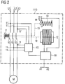
- the control magnet 12 After de-energizing the control magnet 12 is also checked by an evaluation device 15 by means of the electrodes 11 and 11 ', whether the contact bridges have exceeded the predetermined opening point.
- an evaluation device 15 To measure a voltage drop across the main contacts 10 are in the present embodiment for each current path L1-L3 two electrodes 11 and 11 ', once before the main contact 10 and once after the main contact 10, is provided. According to the invention, a voltage test on the main contacts 10 is then made by the evaluation device 15 via the electrodes 11 and 11 'after the main contacts 10 have been switched off. If the voltage drop across one of the main contacts 10 is too small, this is an indication that it has not opened far enough. That is, the opening distance traveled by the contact bridge when it is turned off has not exceeded the predetermined value, and there is a high probability of welding.
- the evaluation device 15 is connected via an unspecified connection with the control device 16. If such an error is detected by the evaluation device 15, it is forwarded to the control device 16, whereupon it interrupts at least one of the control lines.
- a trigger mechanism 14 is activated in the present embodiment, with a spring energy storage device 13 is unlatched.
- spring energy storage 13 may be, for example, already known of circuit breakers or compact starters switching locks.
- Such a switch lock then strikes by means of a mechanical operative connection 19 with high force on the non-opened main contacts 10 of the switching points of the switching device 110 in order to break the welded main contacts 10.
- the force of the spring accumulator 13 must be dimensioned correspondingly large.
- the spring accumulator 13 then either remains in the unlatched position and can not be reset, or the spring accumulator 13 has a mechanism by means of which the spring 13 again stretched and the trigger mechanism 14 can be latched again. Since the resetting of the mechanism 13 and 14 can only be done manually, a user is made aware of the accident and must accordingly, for example, by an exchange of the switching device 110, respond to it.
- only one current sensor per flow path can be provided. Then it is detected by the current measurement in each of the current paths, whether the opening point has been exceeded after switching off. If it has been detected on the basis of the current measurement that an exceeding of the opening point has not occurred, the further operation of the switching device is interrupted.
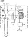
- FIG. 4 shows a third embodiment of the device according to the invention.
- a further switching element 39 ' is provided for interrupting the further operation, which is arranged in the individual current paths L1-L3 in series with the actual switching main contacts 30.
- the evaluation device 35 recognizes by means of the electrodes 31 and 31 'too low a voltage drop at this main contact 30.
- the evaluation device 35 causes a trigger mechanism 34 is activated and thus a spring energy storage 33 is unlatched.
- This spring energy storage 33 acts on the operative connection 39 on the switching element 39 'and opens it.
- the current paths L1-L3 are safely and independently of whether the main contacts 30 are open or closed, interrupted, and the further operation of the switching device 310 is prevented.
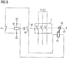
- FIG. 5 shows a fourth embodiment of the device according to the invention.
- the device has an auxiliary contact as Switch monitoring means 45 which is connected in series with a normally closed contact 41 of a control magnet 42 and electromagnetic drive 42.
- the normally closed contact 41 is, as shown, when you turn on, that is, upon energization of the control solenoid 42, opened.
- an actuator 44 is connected, which in the energized or energized state an opening means 46, such as a force accumulator or, as in FIG. 5 shown, can trigger a key lock.
- the control magnet 42 actuates a contact lever 43 via a drive lever 43, which can open and close the main contacts 1, wherein the main contacts 1 are closed in proper operation in the energized state of the control magnet 42, in which a contact load spring 40, the main contacts 1 closes.
- the auxiliary contact 45 is mechanically connected by means of an auxiliary contact slide 48 and the contact slide 43 with the main contacts 1, so that this is the switching state of the main contacts 1 to the auxiliary contact 45 "mirrored", that is transmitted.
- the mechanical connection is made such that in the case of welding at least one main contact 1 and the auxiliary contact 45 is closed or remains closed.
- the switch monitoring means 45 is brought into a first state when the main contacts 1 are closed when the device is switched on.
- the normally closed contact 41 is opened.
- the NC contact 41 is closed and the switch monitoring means 45 is opened.
- the switching monitoring means 45 remains after switching off in this first state, when at least one of the main contacts 1 is welded.
- the actuator 44 can now be energized.
- the actuator 44 may, for example, a Be lifting magnet, which then in the energized case, the breaking means 46, such as a spring memory, releases or the switching mechanism 46 triggers.
- the breaking means 46 such as a spring memory
- the switching voltage is usually “taken away", that is to say that the switching voltage for the electrical supply, in particular of the control magnet, is interrupted, it is advantageous if the switching voltage is reduced by means of an electrical storage element, e.g. a capacitor, is buffered.
- the capacitor voltage can be separated by a diode from the switching voltage.
- the switching device can be used particularly advantageously in a compact starter, in which both the contact opening during operational closing and a disconnection in the event of overcurrent are effected only by a main contact arrangement.
- FIG. 7 shows a fifth embodiment of the device according to the invention in detail.
- a switching mechanism 46 with an integrated spring memory as a force element for breaking a welded main contact 1 shown.
- the combined switching mechanism 46 acts in the case of a triggering via two rams 47, 51 which are mechanically in operative connection with each other, for example, directly on the movable contact bridge.
- a welded main contact 1 can be broken thereby.
- An actuator 44 as a trigger unit is connected by means of an exemplary rotatably mounted lever 52 to the switching mechanism 46.
- the actuator 44 is preferably a plunger anchor or a solenoid. To trigger the actuator 44 is supplied with power. This is done in an analogous manner as in the device according to FIG. 5 and FIG.
- the normally closed contact 41 and the release means 45 designed as a switching contact are actuated correctly with respect to one another in terms of time.
- opening the normally closed contact 41 opens in time before closing the release means 45 and when closing the normally closed contact 41 temporally after the opening of the release means 45 closes.
- the switching voltage for switching on and off of the switching device which is applied to the electrical terminals A3 and A4 for energizing the excitation coil 56 of the control magnet 42, are buffered via a diode for voltage decoupling and a downstream capacitor. Thereby is a sufficient electrical energy for triggering the force element 46 and the switching mechanism 46 upon removal of the switching voltage for switching off the device in case of failure available.
- the course of the magnetic field MF1 originating from the permanent magnets 68 is shown as a dot-dash line.
- the course of the resulting from the permanent magnet 68 magnetic field MF2 for the ON position of the electromagnetic drive 60 is located. In the latter case, there is no way with a low magnetic resistance for the magnetic field MF2 via the outer yoke 64, so that inevitably forms a stray magnetic field around the respective permanent magnet 68.
- a change in the magnetic flux, in particular outside the exciter coil 66 and in particular outside the inner yoke 65 of the electromagnetic drive 60 surrounding the exciter coil 66, can now be detected by means of a suitable measuring means.
- a particularly advantageous measuring coil 62 is wound around a leg of the outer yoke 64.
- a magnetic field sensor such as a Hall sensor, can be used. Starting from the OFF position, the magnetic flux MF1 flows through the measuring coil 62 stationary. If the armature 60 suddenly moves to the left in the ON position, the course of the magnetic flux also changes abruptly in such a way that a stray field MF2, as shown in FIG FIG.
- a particular advantage here is that even creeping wear of the drive mechanism of the electromagnetic drive 60 can be determined, which then lead to slower switching operations with a lower induction voltage u i .
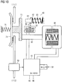
- the essential aspect of the device according to FIG. 10 is that an energy buffering occurs during operation, so that when you turn off and thus after removal of the power supply, the electrical supply of an evaluation and control unit can be guaranteed for a minimum time to optionally trigger a contact breaker and / or switch lock in the presence of a welded main contact or released.
- the control solenoid 92 shown actuates when actuated to turn on the switching device an armature 97 which is in a mechanical operative connection with a contact slide 73, which in turn acts on a contact bridge 74.
- the contact bridge 74 then bridges as a movable line piece, the fixed line sections of the current paths L1-L3.
- contact load spring 75 When switching on the control magnet 92 a biased in the off state of the switching device contact load spring 75 is released, which then presses the contact bridge 74 against the fixed line sections of the current paths L1-L3 and contacted.
- a welded main contact 1 and a switching mechanism can be controlled, which is designed to construct a welded main contact 1 usually can.
- Reference numeral 93 denotes means for detecting at least one welded main contact 1.
- the means are used according to the invention for detecting whether the movable contact bridge 74 of the at least one main contact 1 has exceeded an opening point after switching off.
- the means 93 is a current sensor, in particular a 3-fold current sensor for detecting the current flow in the main current paths L1-L3 of a 3-pole switching device.
- the current sensor 93 is connected via a connecting line for outputting a measured current value to the evaluation and control unit 91.
- the further operation of the switching device is interrupted when the opening point is not exceeded after a predetermined period of time.
- the release means 95 is, for example, an actuator in the form of a lifting or submersible magnet whose actuator armature 96 releases the release means 80 in the form of a spring accumulator.
- the inductance of the electromagnetic drive and thus the OFF position of the main contacts 1 could be determined via a metrological feedback. Or it could be via an auxiliary switch, such as a mirror contact according to IEC 60947-4-1, which is electrically connected to the evaluation and control unit 91, be determined whether the main contacts have opened 1. If it is determined that the main contacts 1 are not open, the energy store 94 is discharged via the release means 95.
- the current transformer (s) 93 could be dimensioned to be larger enough that the energy needed to operate the evaluation and control unit 91 and to trigger the release means 95 can be tapped off via the current transformers 93 from the main current paths L1-L3.
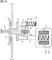
- FIG. 12 shows the seventh embodiment of the device according to the invention with closed main contacts 1.
- the excitation coil of the control magnet 72 via the electrical Connections A5, A6 energized.
- the armature 77 moves in the example of FIG. 12 to the right and relieves the contact slide 73. By this relief and by the relaxation of the preloaded contact load spring 75 now closes the contact bridge 74, the main contacts. 1
- the release means 85 for the contact breaker means 80 and at the same time a few moments thereafter the control magnet 72 is energized.
- the return spring of the release means 85 continues to be actively biased.
- the actuation delay of the control magnet 72 relative to the release means 85 can be done for example by mechanical damping means which act only for the switch-on.
- electrical damping means in the field circuit of the control magnet 72 can be used, such as a series connected to the excitation coil of the control magnet 72 throttle.
- Actuator armature 86 now does not release the contact break-up means 80, although armature 77 of control magnet 72 releases the stop or retention function as a result of the actuation which now begins.
- FIG. 12 shows due to the actuation of the armature 77 to the connector 76, a gap of a few millimeters, due to the new state of the Switching contacts 1 sets. This gap is reduced with the wear of the contact material.
- the end of the actuator armature 86 which lies opposite the locking tooth, now faces the connecting piece 76.
- the connecting piece 76 has a recess 78 in the region of the actuator armature 86, irrespective of whether the main contacts 1 are new or already worn.
- the recess 78 is dimensioned such that when the release means 86, ie the actuator designed as a lifting or submersible magnet, drops off, the contact opening means 80 is reliably released.
- the connecting piece 76 could also have a constant cross-section over its entire length corresponding to the dimensions of the connecting piece 76 in the end region.
- FIG. 13 shows the seventh embodiment of the device according to the invention with a welded main contact 1 with not yet released Kunststoffetzbrechsch 80.
- the switching off of the control unit is usually carried out in that the switching voltage at the terminals A5 and A6 of the control magnet 72 is interrupted or removed.
- the switching voltage also feeds the release means 85 via the terminals A7 and A8, so that after removal of the switching voltage, this also drops.
- the exciter circuits of the control magnet 72 and the release means 85 may also be connected in series.
- the switching device now detects or checks whether the movable contact bridge 74 of the at least one main contact 1 has exceeded an opening point after switching off.
- the predetermined period of time may be, for example, 100 ms.
- the release means 85 preferably decelerates when it is switched off relative to the control magnet 72, so that the armature 77 can again assume the stop and retention function for the actuator armature 86 when it is switched off.
- the further operation of the switching device is interrupted after the predetermined period of time, when the anchor 77 is no longer actuated due to a welded main contact 1, so that he could still "catch” the already falling actuator anchor 86.
- the release agent 85 now drops completely, thereby releasing the contact breaker 80.
- the fall-off delay on turning off the actuator 85 may be e.g. take place by means of mechanical damping systems or by means of an electric freewheeling circuit with a freewheeling diode in the excitation circuit of the actuator 85.
- the freewheeling circuit maintains the magnetization of the magnetic circuit of the actuator 85 for the predetermined period of time.
- the exciter circuit of the control magnet 72 can be electrically attenuated by means of a relatively high-impedance resistor, so that very quickly the magnetic energy in the magnetic circuit of the control magnet 72 can be reduced.
- the spring force of the spring of the contact breaker 80 is dimensioned so that it can overcome the required Aufbrechkraft in addition to the opposite spring force of the contact load spring 75. Re-closing the main contacts 1 is no longer possible. The operation of the switching device is thus interrupted.
- the contact break-up means 80 may also include a mechanism, not shown, which allows to tension the released spring 83 and the release means 85 again. This reset of the mechanism can be done manually, for example.
Landscapes
- Physics & Mathematics (AREA)
- General Physics & Mathematics (AREA)
- Keying Circuit Devices (AREA)
- Driving Mechanisms And Operating Circuits Of Arc-Extinguishing High-Tension Switches (AREA)
Claims (41)
- Procédé pour le fonctionnement sûr d'un appareil de commutation comportant au moins un contact principal pouvant être enclenché et coupé et qui comporte des pièces de contact et un pont de contact mobile, et au moins un aimant de commande qui comporte un induit mobile, l'induit agissant de manière telle sur le pont de contact, à l'enclenchement et à la coupure, que le contact principal correspondant s'ouvre et se ferme,
comportant les étapes suivantes :a) reconnaître si le pont de contact mobile de l'au moins un contact principal a dépassé un point d'ouverture après la coupure,
caractérisé par uneb) interruption de la poursuite du fonctionnement de l'appareil de commutation et activation d'un moyen de forçage du contact en ouverture (46 ; 80) si le point d'ouverture n'est pas dépassé après une durée de temps spécifiée. - Procédé selon la revendication 1, caractérisé en ce que le dépassement du point d'ouverture est reconnu par une mesure d'un courant dans une voie de passage du courant à commuter par le contact principal, le point d'ouverture n'étant pas dépassé si le courant mesuré est supérieur à un courant prévu après la coupure.
- Procédé selon la revendication 1, caractérisé en ce que le dépassement du point d'ouverture est reconnu par une mesure d'une chute de tension via un contact principal, le point d'ouverture n'étant pas dépassé si la chute de tension est inférieure à une chute de tension prévue après la coupure.
- Procédé selon la revendication 1, caractérisé en ce que le dépassement du point d'ouverture est reconnu par une mesure d'une inductance de l'aimant de commande, le point d'ouverture n'étant pas dépassé si l'inductance présente, après la coupure, une valeur qui ne correspond pas à la valeur spécifiée après l'ouverture.
- Procédé selon la revendication 1, caractérisé en ce que le point d'ouverture est reconnu par un état de moyens en liaison active avec le pont de contact, le point d'ouverture reconnu n'étant pas dépassé si ces moyens restent, après la coupure, dans cet état qui ne correspond pas à l'état spécifié après la coupure.
- Procédé selon la revendication 5, caractérisé en ce que :- un contact auxiliaire (45) se ferme à l'enclenchement ou pour l'enclenchement d'un aimant de commande (42) ;- un contact d'ouverture (41) s'ouvre à l'enclenchement de l'aimant de commande (42) et- un moyen de libération (44) monté en série avec les contacts de commutation (41, 45) et qui déclenche le moyen de forçage du contact en ouverture (46) si le contact auxiliaire (45) reste resp. est resté à l'état fermé à la coupure.
- Procédé selon la revendication 6, caractérisé en ce que les contacts de commutation (41, 45) sont réalisés de telle sorte que le contact auxiliaire (45) se ferme à l'enclenchement après que le contact d'ouverture (41) s'est ouvert et en ce que le contact d'ouverture (41) se ferme à la coupure après que le contact auxiliaire (45) s'est ouvert.
- Procédé selon la revendication 5, caractérisé en ce que :- un contact auxiliaire s'ouvre à l'enclenchement ou pour l'enclenchement d'un aimant de commande (42) ;- un contact de fermeture se ferme à l'enclenchement de l'aimant de commande (42) et- un moyen de libération déclenche le moyen de forçage du contact en ouverture (46) si le contact auxiliaire reste resp. est resté à l'état ouvert à la coupure par évaluation de l'état de commutation respectivement ouvert desdits contacts de commutation.
- Procédé selon la revendication 8, caractérisé en ce que lesdits contacts de commutation sont réalisés de telle sorte que le contact auxiliaire s'ouvre à l'enclenchement après que le contact de fermeture s'est fermé et en ce que le contact de fermeture s'ouvre à la coupure après que le contact auxiliaire s'est fermé.
- Procédé selon la revendication 1, caractérisé en ce qu'une modification du flux magnétique du circuit magnétique de l'aimant de commande (60) est mesurée lors d'une commande de commutation, le point d'ouverture étant dépassé si, à la coupure de l'aimant de commande (60), la modification du flux magnétique a dépassé une valeur de comparaison spécifiée.
- Procédé selon la revendication 10, caractérisé en ce que la modification du flux magnétique est mesurée au moyen d'une bobine d'induction (62).
- Procédé selon la revendication 1, caractérisé en ce que l'alimentation électrique pour une unité d'évaluation et de commande (91) de l'appareil de commutation est maintenue au moyen d'un élément d'accumulation électrique (94) pour un temps minimum pour reconnaître, par une technique de mesure, une présence d'un contact principal soudé (1) et pour commander resp. libérer, le cas échéant, le moyen de forçage du contact en ouverture (80) et/ou un verrou de commutation.
- Procédé selon la revendication 12, caractérisé en ce que l'aimant de commande (92), en présence d'un ordre de commutation, n'est excité pour actionner au moins un contact principal (1) que si l'élément d'accumulation électrique (94) a atteint un état de charge minimum.
- Procédé selon la revendication 1, caractérisé en ce que- à l'état enclenché de l'aimant de commande (72), un moyen de libération (95) est maintenu activement dans un état excité pour empêcher le déclenchement du moyen de forçage du contact en ouverture (80) et- à la coupure, le moyen de libération (85) et l'aimant de commande (72) sont désexcités, un induit (77) ou un composant de l'aimant de commande (72) en liaison mécanique active avec l'induit (77) empêchant alors le déclenchement du moyen de libération (85).
- Procédé selon la revendication 14, caractérisé en ce que, à l'enclenchement, le moyen de libération (85) est excité avant l'aimant de commande (72) et en ce que, à la coupure, l'aimant de commande (72) est désexcité avant le moyen de libération (85).
- Procédé selon la revendication 14 ou 15, caractérisé en ce que le moyen de libération (85) est un aimant de levage ou un aimant plongeant.
- Procédé selon l'une des revendications 14 à 16, caractérisé en ce que le moyen de forçage du contact en ouverture (80) comporte un accumulateur à ressort.
- Procédé selon l'une des revendications précédentes, caractérisé en ce que la poursuite du fonctionnement est interrompue par ouverture d'un élément de commutation monté en série avec le contact principal (1) dans la voie de passage du courant (L1-L3).
- Procédé selon l'une des revendications précédentes, caractérisé en ce que la poursuite du fonctionnement est interrompue par interruption d'au moins une ligne de commande pour la commande de l'aimant de commande.
- Dispositif pour le fonctionnement sûr d'un appareil de commutation, l'appareil de commutation comprenant au moins un contact principal pouvant être enclenché et coupé et comportant des pièces de contact et un pont de contact mobile, et au moins un aimant de commande comportant un induit mobile, et l'induit, à l'enclenchement et à la coupure, agissant de manière telle sur le pont de contact que le contact principal correspondant peut se fermer et s'ouvrir, avec :- des premiers moyens pour reconnaître si un point d'ouverture du pont de contact de l'au moins un contact principal a été dépassé,caractérisé par
d'autres moyens qui interrompent la poursuite du fonctionnement de l'appareil de commutation et activent un moyen de forçage du contact en ouverture (46 ; 80) lorsque les moyens, après la coupure, reconnaissent que le point d'ouverture n'est pas dépassé après une durée de temps spécifiée. - Dispositif selon la revendication 20, caractérisé en ce que les premiers moyens comprennent un capteur de courant qui mesure le courant dans une voie de passage du courant à commuter par le contact principal.
- Dispositif selon la revendication 20, caractérisé en ce que les premiers moyens comprennent deux électrodes, la première et la deuxième électrode étant agencées de telle sorte qu'il est possible de déduire une chute de tension via le contact principal.
- Dispositif selon la revendication 20, caractérisé en ce que les premiers moyens comprennent un moyen de détection d'une inductance qui mesure l'inductance de l'aimant de commande.
- Dispositif selon la revendication 20, caractérisé en ce que les premiers moyens comprennent une mécanique d'ouverture qui est en liaison active avec le pont de contact et peut se mettre dans un premier et un deuxième état.
- Dispositif selon la revendication 24, caractérisé en ce que :- il est prévu un contact auxiliaire (45) qui se ferme à l'enclenchement de l'aimant de commande (42) resp. qui se ferme pour l'enclenchement de l'aimant de commande (42) ;- un contact d'ouverture (41) est prévu et est réalisé de telle sorte que celui-ci s'ouvre à l'enclenchement de l'aimant de commande (42) et- il est prévu un moyen de libération (44) qui est monté en série avec les contacts de commutation (41, 45) et qui déclenche le moyen de forçage du contact en ouverture (46) lorsque le contact auxiliaire (45), à la coupure, reste resp. est resté à l'état fermé.
- Dispositif selon la revendication 25, caractérisé en ce que les contacts de commutation (41,45) sont réalisés de telle sorte que le contact auxiliaire (45) se ferme à l'enclenchement après que le contact d'ouverture (41) s'est ouvert et en ce que le contact d'ouverture (41) se ferme à la coupure après que le contact auxiliaire (45) s'est ouvert.
- Dispositif selon la revendication 24, caractérisé en ce que :- il est prévu un contact auxiliaire qui s'ouvre à l'enclenchement de l'aimant de commande (42) resp. qui s'ouvre pour l'enclenchement de l'aimant de commande (42) ;- un contact de fermeture est prévu et est réalisé de telle sorte que celui-ci se ferme à l'enclenchement de l'aimant de commande (42) et- il est prévu un moyen de libération qui déclenche le moyen de forçage du contact en ouverture (46), lorsque le contact auxiliaire, à la coupure, reste resp. est resté à l'état ouvert, par évaluation, par des moyens d'évaluation, de l'état de commutation respectivement ouvert desdits contacts de commutation.
- Dispositif selon la revendication 27, caractérisé en ce que les contacts de commutation sont réalisés de telle sorte que le contact auxiliaire s'ouvre à l'enclenchement après que le contact de fermeture s'est fermé et en ce que le contact de fermeture s'ouvre à la coupure après que le contact auxiliaire s'est fermé.
- Dispositif selon la revendication 20, caractérisé en ce qu'est prévu un moyen de détection d'une modification du flux magnétique du circuit magnétique de l'aimant de commande (60) en cas de commande de commutation, le point d'ouverture étant dépassé si, à la coupure de l'aimant de commande (60), la modification du flux magnétique a dépassé une valeur de comparaison spécifiée.
- Dispositif selon la revendication 29, caractérisé en ce que la modification du flux magnétique peut être mesurée au moyen d'une bobine d'induction (62).
- Dispositif selon la revendication 20, caractérisé en ce qu'est prévu un élément d'accumulation électrique (94) pour maintenir l'alimentation électrique pour une unité d'évaluation et de commande (91) de l'appareil de commutation pour un temps minimum pour reconnaître, par une technique de mesure, une présence d'un contact principal soudé (1) et pour commander resp. libérer, le cas échéant, le moyen de forçage du contact en ouverture (80) et/ou un verrou de commutation.
- Dispositif selon la revendication 31, caractérisé en ce que sont prévus des moyens (91) qui, en présence d'un ordre de commutation, n'excitent l'aimant de commande (92) pour actionner au moins un contact principal (1) que si l'élément d'accumulation électrique (94) a atteint un état de charge minimum.
- Dispositif selon la revendication 20, caractérisé en ce que :- il est prévu un moyen de libération (85) qui, à l'état enclenché de l'aimant de commande (72), est maintenu activement dans un état excité pour empêcher le déclenchement du moyen de forçage du contact en ouverture (80) et- à la coupure, le moyen de libération (85) et l'aimant de commande (72) sont désexcités, un induit (77) ou un composant de l'aimant de commande (72) en liaison mécanique active avec l'induit (77) empêchant alors le déclenchement du moyen de libération (85).
- Dispositif selon la revendication 33, caractérisé en ce que sont prévus des moyens qui, à l'enclenchement, désexcitent le moyen de libération (85) avant l'aimant de commande (72) dans le temps et qui, à la coupure, désexcitent l'aimant de commande (72) avant le moyen de libération (85) dans le temps.
- Dispositif selon la revendication 33 ou 34, caractérisé en ce que le moyen de libération (85) est un aimant de levage ou un aimant plongeant.
- Dispositif selon l'une des revendications 33 à 35, caractérisé en ce que le moyen de forçage du contact en ouverture (80) comporte un accumulateur à ressort.
- Dispositif selon l'une des revendications 20 à 36, caractérisé en ce que les autres moyens comprennent un dispositif d'évaluation qui, pour interrompre la poursuite du fonctionnement, ouvre un élément de commutation monté en série avec le contact principal dans la voie de passage du courant.
- Dispositif selon l'une des revendications 20 à 37, caractérisé en ce que les autres moyens comprennent un dispositif de commande pour commander l'aimant de commande, lequel dispositif interrompt la ligne de commande vers l'aimant de commande pour interrompre la poursuite du fonctionnement.
- Appareil de commutation qui exécute le procédé selon l'une des revendications 1 à 19 pour la commutation sûre de consommateurs, l'appareil de commutation étant un contacteur ou un disjoncteur ou une dérivation compacte.
- Appareil de commutation pour la commutation sûre de consommateurs avec un dispositif selon l'une des revendications 20 à 38, l'appareil de commutation étant un contacteur ou un disjoncteur ou une dérivation compacte.
- Appareil de commutation selon la revendication 39 ou 40, caractérisé en ce que l'appareil de commutation est un l'appareil de commutation tripolaire avec trois contacts principaux pour enclencher et couper trois voies de passage du courant avec un aimant de commande.
Applications Claiming Priority (3)
| Application Number | Priority Date | Filing Date | Title |
|---|---|---|---|
| DE102004062266A DE102004062266A1 (de) | 2004-12-23 | 2004-12-23 | Verfahren und Vorrichtung zum sicheren Betrieb eines Schaltgerätes |
| DE102004062267A DE102004062267A1 (de) | 2004-12-23 | 2004-12-23 | Verfahren und Vorrichtung zum sicheren Betrieb eines Schaltgerätes |
| PCT/EP2005/057109 WO2006069970A1 (fr) | 2004-12-23 | 2005-12-22 | Procede et dispositif pour le fonctionnement sur d'un appareil de commutation |
Publications (2)
| Publication Number | Publication Date |
|---|---|
| EP1829068A1 EP1829068A1 (fr) | 2007-09-05 |
| EP1829068B1 true EP1829068B1 (fr) | 2018-09-12 |
Family
ID=36013180
Family Applications (1)
| Application Number | Title | Priority Date | Filing Date |
|---|---|---|---|
| EP05850489.5A Expired - Lifetime EP1829068B1 (fr) | 2004-12-23 | 2005-12-22 | Procede et dispositif pour le fonctionnement sur d'un appareil de commutation |
Country Status (7)
| Country | Link |
|---|---|
| US (1) | US7692522B2 (fr) |
| EP (1) | EP1829068B1 (fr) |
| JP (1) | JP5188812B2 (fr) |
| KR (1) | KR100927490B1 (fr) |
| CN (1) | CN101084561B (fr) |
| BR (1) | BRPI0519197A2 (fr) |
| WO (1) | WO2006069970A1 (fr) |
Cited By (3)
| Publication number | Priority date | Publication date | Assignee | Title |
|---|---|---|---|---|
| DE102020210206B3 (de) | 2020-08-12 | 2022-01-20 | Siemens Aktiengesellschaft | Ansteuerschaltung für einen elektromagnetischen Aktor, Verfahren zum Ansteuern eines elektromagnetischen Aktors sowie Mittelspannungsleistungsschalter mit einem elektromagneti-schen Aktor und der Ansteuerschaltung |
| DE102021208400A1 (de) | 2021-08-03 | 2023-02-09 | Siemens Aktiengesellschaft | Vakuumschaltanordnung und Verfahren zum Trennen verschweißter Kontakte einer Vakuumschaltanordnung |
| WO2023237394A1 (fr) * | 2022-06-09 | 2023-12-14 | Siemens Energy Global GmbH & Co. KG | Contacteur pour ouvrir et fermer un trajet de courant |
Families Citing this family (47)
| Publication number | Priority date | Publication date | Assignee | Title |
|---|---|---|---|---|
| DE102004062267A1 (de) | 2004-12-23 | 2006-07-13 | Siemens Ag | Verfahren und Vorrichtung zum sicheren Betrieb eines Schaltgerätes |
| DE102004062266A1 (de) * | 2004-12-23 | 2006-07-13 | Siemens Ag | Verfahren und Vorrichtung zum sicheren Betrieb eines Schaltgerätes |
| CN101316742B (zh) * | 2005-10-13 | 2011-02-09 | Trw汽车美国有限责任公司 | 控制车辆中的可致动约束系统的装置 |
| DE102006055007A1 (de) * | 2006-11-22 | 2008-05-29 | Abb Ag | Installationsschaltgerät mit einer Doppelunterbrechung |
| CN101902025B (zh) * | 2009-05-31 | 2013-03-20 | 西门子公司 | 一种电路安全防护的方法和装置 |
| US8552728B2 (en) * | 2009-11-30 | 2013-10-08 | Utility Relay Co., Ltd. | Sluggish circuit breaker detection system and method |
| JP5029731B2 (ja) * | 2010-07-08 | 2012-09-19 | 富士電機機器制御株式会社 | 電磁接触器 |
| JP5307779B2 (ja) | 2010-08-31 | 2013-10-02 | 富士電機機器制御株式会社 | 電磁開閉器 |
| CN102005343B (zh) * | 2010-10-22 | 2015-01-14 | 国家电网公司 | 防接点粘连的断路器 |
| JP2012199115A (ja) * | 2011-03-22 | 2012-10-18 | Panasonic Corp | 電磁開閉装置 |
| DE102011081773A1 (de) | 2011-08-30 | 2013-02-28 | Siemens Aktiengesellschaft | Verfahren zum Betreiben eines elektrischen Geräts sowie Leistungsschalter |
| JP6206697B2 (ja) * | 2012-11-30 | 2017-10-04 | 富士電機機器制御株式会社 | 電磁開閉器 |
| FR3011673B1 (fr) * | 2013-10-08 | 2015-12-11 | Schneider Electric Ind Sas | Dispositif de commutation et procede de detection d'un defaut d'un tel dispositif de commutation |
| US10109444B2 (en) * | 2013-12-17 | 2018-10-23 | Siemens Aktiengesellschaft | Electronic module for protecting a HVDC converter from current surges of energy discharges from a capacitor of the converter |
| DE102014206366B4 (de) * | 2014-04-03 | 2022-08-04 | Siemens Aktiengesellschaft | Verfahren zur Prüfung eines Selbsthaltemagneten eines Schalters und Prüfeinrichtung für den Selbsthaltemagneten |
| JP6202200B2 (ja) * | 2014-05-20 | 2017-09-27 | 富士電機機器制御株式会社 | 電磁接触器 |
| US11170956B2 (en) | 2014-06-25 | 2021-11-09 | Te Connectivity Germany Gmbh | Switching arrangement |
| DE102014212132A1 (de) * | 2014-06-25 | 2015-12-31 | Te Connectivity Germany Gmbh | Schaltanordnung |
| CN104599901B (zh) * | 2015-02-03 | 2017-05-10 | 珠海格力电器股份有限公司 | 用于接触器的检测电路 |
| CN106257295B (zh) * | 2015-06-19 | 2023-09-12 | 浙江正泰电器股份有限公司 | 断路器 |
| AU2016277616B2 (en) * | 2015-12-23 | 2021-05-27 | Schneider Electric Industries Sas | A method for detecting a fault in a recloser |
| US10111540B2 (en) * | 2016-03-17 | 2018-10-30 | Fasteners For Retail, Inc. | Actuator with time delay |
| FR3054369B1 (fr) | 2016-07-20 | 2022-05-27 | Zodiac Aero Electric | Contacteur electromagnetique dote de moyens de detection de la position ouverte ou fermee de commutateurs commandes |
| US10332698B2 (en) * | 2016-12-21 | 2019-06-25 | Eaton Intelligent Power Limited | System and method for monitoring contact life of a circuit interrupter |
| KR102201347B1 (ko) * | 2017-06-15 | 2021-01-08 | 주식회사 엘지화학 | 배터리 모듈과 이를 포함하는 배터리 팩 및 자동차 |
| KR102201342B1 (ko) * | 2017-07-06 | 2021-01-08 | 주식회사 엘지화학 | 배터리 모듈과 이를 포함하는 배터리 팩 및 자동차 |
| FR3069064B1 (fr) * | 2017-07-13 | 2022-02-11 | Schneider Electric Ind Sas | Dispositif de commutation electrique et procede de detection d'usure associe |
| JP6819527B2 (ja) * | 2017-09-22 | 2021-01-27 | ブラザー工業株式会社 | 検出装置及び工作機械 |
| GB2569978B (en) | 2018-01-05 | 2020-07-01 | Apollo Fire Detectors Ltd | Relay protection |
| DE102018110919A1 (de) * | 2018-05-07 | 2019-11-07 | Tdk Electronics Ag | Schaltvorrichtung |
| JP2020004848A (ja) * | 2018-06-28 | 2020-01-09 | 日本電産トーソク株式会社 | ソレノイド装置 |
| FR3087273B1 (fr) * | 2018-10-15 | 2020-11-06 | Schneider Electric Ind Sas | Dispositif de mesure et appareil de commutation electrique |
| FR3093227B1 (fr) * | 2019-02-21 | 2021-02-12 | Schneider Electric Ind Sas | Dispositif de commande de contacts d’une ampoule à vide pour appareil de connexion électrique |
| CN110676092B (zh) * | 2019-10-18 | 2025-02-28 | 中国铁道科学研究院集团有限公司 | 基于开关设备多路反馈信号的控制系统 |
| BR112022007861B1 (pt) * | 2019-12-05 | 2023-03-14 | S&C Electric Company | Métodos para operar um conjunto de comutador, para realizar uma operação de teste de fuga de religamento e para realizar uma operação de teste de pulso de baixa energia, e, sistema para usar um conjunto de comutador |
| US11403906B2 (en) * | 2020-01-15 | 2022-08-02 | Fasteners For Retail, Inc. | Actuator with locking mechanism |
| CN111722103B (zh) * | 2020-06-08 | 2023-05-09 | 国网辽宁省电力有限公司电力科学研究院 | 一种252kV GIS隔离开关速度及行程的计算方法 |
| CN111916309A (zh) * | 2020-08-13 | 2020-11-10 | 国网河南省电力公司灵宝市供电公司 | 一种无塔上水器压力开关保护装置 |
| GB2598358A (en) * | 2020-08-28 | 2022-03-02 | Eaton Intelligent Power Ltd | Contactor and method for observing a contactor |
| DE102020124802A1 (de) | 2020-09-23 | 2022-03-24 | Te Connectivity Germany Gmbh | Schaltanordnung und Verfahren zum Messen einer Position einer Kontaktbrücke in einer Schaltanordnung |
| CN115144744A (zh) * | 2022-08-03 | 2022-10-04 | 阳光电源股份有限公司 | 逆变器及其交流侧开关失效检测方法 |
| FR3151133B1 (fr) * | 2023-07-13 | 2025-06-13 | Schneider Electric Ind Sas | Procédé de détection d’une dégradation d'un appareil de commutation comprenant un actionneur électromagnétique |
| FR3151130B1 (fr) * | 2023-07-13 | 2025-06-13 | Schneider Electric Ind Sas | Procédé de détection d’une dégradation d'un appareil de commutation |
| CN118150135B (zh) * | 2023-12-29 | 2024-12-03 | 扬州新概念电气有限公司 | 一种断路器机械特性测试方法、测试装置及测试系统 |
| WO2026008439A1 (fr) * | 2024-07-02 | 2026-01-08 | Eaton Intelligent Power Limited | Procédé de détermination d'usure de contact d'un dispositif de commutation, et dispositif de commutation |
| US20260011512A1 (en) * | 2024-07-05 | 2026-01-08 | Te Connectivity Solutions Gmbh | Power Switching Device with Self Diagnostic Capability |
| CN118795326B (zh) * | 2024-09-14 | 2025-01-24 | 国网上海市电力公司 | 手车断路器状态在线监测方法及装置 |
Family Cites Families (17)
| Publication number | Priority date | Publication date | Assignee | Title |
|---|---|---|---|---|
| DE3540460A1 (de) * | 1985-11-14 | 1987-05-21 | Siemens Ag | Elektromagnetisches schaltgeraet |
| US5243291A (en) * | 1991-10-11 | 1993-09-07 | Shinkoh Electric Co., Ltd. | Electromagnetic contactor deposition detecting apparatus which detects load current and switch current |
| CA2093064C (fr) * | 1992-06-10 | 1998-08-11 | Dennis W. Waggamon | Circuit de controle d'etat |
| DE4427006A1 (de) | 1994-07-29 | 1996-02-01 | Siemens Ag | Verfahren zur Bestimmung der Restlebensdauer von Kontakten in Schaltgeräten und zugehörige Anordnung |
| JP3358330B2 (ja) * | 1994-10-06 | 2002-12-16 | 日本精工株式会社 | 電動パワーステアリング装置の制御装置 |
| JP3427520B2 (ja) * | 1994-10-14 | 2003-07-22 | 日本精工株式会社 | 電動パワーステアリング装置の制御装置 |
| SE515261C2 (sv) * | 1995-06-12 | 2001-07-09 | Abb Research Ltd | Kontaktorutrustning |
| DE19603310A1 (de) * | 1996-01-31 | 1997-08-07 | Siemens Ag | Verfahren zur Bestimmung der Restlebensdauer von Kontakten in Schaltgeräten und zugehörige Anordnung |
| JPH09259724A (ja) * | 1996-03-26 | 1997-10-03 | Matsushita Electric Works Ltd | 負荷制御装置 |
| US5754387A (en) * | 1996-06-13 | 1998-05-19 | Eaton Corporation | Method of monitoring contactor operation |
| DZ2952A1 (fr) * | 1998-12-01 | 2004-03-15 | Schneider Electric Ind Sa | Conacteur électromécanique logeant dans un corps un électroaimant et un porte-contacts mobile. |
| US5917394A (en) * | 1998-12-01 | 1999-06-29 | Fuchs; Michael J | Solenoid switch modified for higher current passage |
| CN1252768C (zh) * | 1999-12-03 | 2006-04-19 | 西门子公司 | 带有受控驱动装置的电磁开关设备以及相应方法和电路 |
| DE10148155A1 (de) * | 2001-09-28 | 2003-04-24 | Moeller Gmbh | Anordnung zur Überwachung von Motorstartern |
| US6958671B2 (en) * | 2001-11-15 | 2005-10-25 | Square D Company | Electrical contactor with positive temperature coefficient resistivity element |
| JP2004055497A (ja) * | 2002-07-24 | 2004-02-19 | Mitsuba Corp | 高電圧大電流用電磁継電器 |
| DE102004062267A1 (de) | 2004-12-23 | 2006-07-13 | Siemens Ag | Verfahren und Vorrichtung zum sicheren Betrieb eines Schaltgerätes |
-
2005
- 2005-12-22 KR KR1020077016499A patent/KR100927490B1/ko not_active Expired - Fee Related
- 2005-12-22 JP JP2007547537A patent/JP5188812B2/ja not_active Expired - Fee Related
- 2005-12-22 CN CN2005800437898A patent/CN101084561B/zh not_active Expired - Fee Related
- 2005-12-22 US US11/793,697 patent/US7692522B2/en active Active
- 2005-12-22 BR BRPI0519197-1A patent/BRPI0519197A2/pt not_active IP Right Cessation
- 2005-12-22 WO PCT/EP2005/057109 patent/WO2006069970A1/fr not_active Ceased
- 2005-12-22 EP EP05850489.5A patent/EP1829068B1/fr not_active Expired - Lifetime
Non-Patent Citations (1)
| Title |
|---|
| None * |
Cited By (4)
| Publication number | Priority date | Publication date | Assignee | Title |
|---|---|---|---|---|
| DE102020210206B3 (de) | 2020-08-12 | 2022-01-20 | Siemens Aktiengesellschaft | Ansteuerschaltung für einen elektromagnetischen Aktor, Verfahren zum Ansteuern eines elektromagnetischen Aktors sowie Mittelspannungsleistungsschalter mit einem elektromagneti-schen Aktor und der Ansteuerschaltung |
| DE102021208400A1 (de) | 2021-08-03 | 2023-02-09 | Siemens Aktiengesellschaft | Vakuumschaltanordnung und Verfahren zum Trennen verschweißter Kontakte einer Vakuumschaltanordnung |
| DE102021208400B4 (de) | 2021-08-03 | 2024-07-11 | Siemens Aktiengesellschaft | Vakuumschaltanordnung und Verfahren zum Trennen verschweißter Kontakte einer Vakuumschaltanordnung |
| WO2023237394A1 (fr) * | 2022-06-09 | 2023-12-14 | Siemens Energy Global GmbH & Co. KG | Contacteur pour ouvrir et fermer un trajet de courant |
Also Published As
| Publication number | Publication date |
|---|---|
| JP2008525950A (ja) | 2008-07-17 |
| CN101084561B (zh) | 2010-05-26 |
| BRPI0519197A2 (pt) | 2008-12-30 |
| US7692522B2 (en) | 2010-04-06 |
| EP1829068A1 (fr) | 2007-09-05 |
| KR20070088796A (ko) | 2007-08-29 |
| WO2006069970A1 (fr) | 2006-07-06 |
| KR100927490B1 (ko) | 2009-11-17 |
| US20080036561A1 (en) | 2008-02-14 |
| CN101084561A (zh) | 2007-12-05 |
| JP5188812B2 (ja) | 2013-04-24 |
Similar Documents
| Publication | Publication Date | Title |
|---|---|---|
| EP1829068B1 (fr) | Procede et dispositif pour le fonctionnement sur d'un appareil de commutation | |
| EP1829067B1 (fr) | Procede et dispositif pour assurer la securite de fonctionnement d'un appareil de distribution | |
| EP2864995B1 (fr) | Contacteur avec verrou de commutation électromagnétique | |
| EP1628317B1 (fr) | Disjoncteur avec indication des fonctions de déclenchement courant de surcharge ou court-circuit et procédé correspondant | |
| EP1089308B1 (fr) | Dispositif pour la fermeture et la coupure d'un circuit de puissance | |
| EP3284097B1 (fr) | Élément de commutation à fermeture rapide | |
| EP1829066B1 (fr) | Procede et dispositif pour assurer la securite de fonctionnement d'un appareil de distribution | |
| DE112005003109B4 (de) | Verfahren und Vorrichtung zum sicheren Betrieb eines Schaltgerätes | |
| DE102021210273A1 (de) | Verfahren zur Bestimmung eines Öffnungszeitpunkts eines Schalters | |
| DE971476C (de) | Elektrischer Selbstschalter mit Fehlerstromausloesung | |
| EP2059942B1 (fr) | Appareil de commutation, notamment dispositif d'amorçage compact | |
| DE102004062267A1 (de) | Verfahren und Vorrichtung zum sicheren Betrieb eines Schaltgerätes | |
| EP2680293B1 (fr) | Mécanisme de déclenchement | |
| WO2008000200A1 (fr) | Procédé et dispositif permettant de faire fonctionner une unité de commutation de manière sûre | |
| DE10005825C2 (de) | Elektrischer Niederspannungsschalter | |
| DE102011079593A1 (de) | Elektromechanisches Schutzschaltgerät | |
| WO2025051489A1 (fr) | Disjoncteur | |
| DE102016203505B4 (de) | Auslösevorrichtung und elektromechanisches Schutzschaltgerät | |
| DE102014111854A1 (de) | Schaltgerät mit Schalt- und Schutzfunktion | |
| DE102024206874A1 (de) | Auslösevorrichtung und Fehlerstromschutzschalter | |
| DE102006031408A1 (de) | Schaltgerät mit Anzeige eines verschweißten Hauptkontakts | |
| DE1588820A1 (de) | Kombination eines polarisierten Relais mit einer magnetisch betaetigten Anordnung | |
| DE102008017273A1 (de) | Elektrischer Selbstschalter | |
| DD257710A1 (de) | Hilfsschalter fuer hochspannungsschaltgeraete | |
| DE102005047043A1 (de) | Leitungsschutzsystem mit mechanisch selektiver Auslösung |
Legal Events
| Date | Code | Title | Description |
|---|---|---|---|
| PUAI | Public reference made under article 153(3) epc to a published international application that has entered the european phase |
Free format text: ORIGINAL CODE: 0009012 |
|
| 17P | Request for examination filed |
Effective date: 20070529 |
|
| AK | Designated contracting states |
Kind code of ref document: A1 Designated state(s): AT BE BG CH CY CZ DE DK EE ES FI FR GB GR HU IE IS IT LI LT LU LV MC NL PL PT RO SE SI SK TR |
|
| DAX | Request for extension of the european patent (deleted) | ||
| 17Q | First examination report despatched |
Effective date: 20090507 |
|
| RAP1 | Party data changed (applicant data changed or rights of an application transferred) |
Owner name: SIEMENS AKTIENGESELLSCHAFT |
|
| RAP1 | Party data changed (applicant data changed or rights of an application transferred) |
Owner name: SIEMENS AKTIENGESELLSCHAFT |
|
| RAP1 | Party data changed (applicant data changed or rights of an application transferred) |
Owner name: SIEMENS AKTIENGESELLSCHAFT |
|
| GRAP | Despatch of communication of intention to grant a patent |
Free format text: ORIGINAL CODE: EPIDOSNIGR1 |
|
| INTG | Intention to grant announced |
Effective date: 20180507 |
|
| GRAS | Grant fee paid |
Free format text: ORIGINAL CODE: EPIDOSNIGR3 |
|
| GRAA | (expected) grant |
Free format text: ORIGINAL CODE: 0009210 |
|
| AK | Designated contracting states |
Kind code of ref document: B1 Designated state(s): AT BE BG CH CY CZ DE DK EE ES FI FR GB GR HU IE IS IT LI LT LU LV MC NL PL PT RO SE SI SK TR |
|
| REG | Reference to a national code |
Ref country code: GB Ref legal event code: FG4D Free format text: NOT ENGLISH |
|
| REG | Reference to a national code |
Ref country code: CH Ref legal event code: EP |
|
| REG | Reference to a national code |
Ref country code: IE Ref legal event code: FG4D Free format text: LANGUAGE OF EP DOCUMENT: GERMAN |
|
| REG | Reference to a national code |
Ref country code: DE Ref legal event code: R096 Ref document number: 502005015907 Country of ref document: DE |
|
| REG | Reference to a national code |
Ref country code: AT Ref legal event code: REF Ref document number: 1041559 Country of ref document: AT Kind code of ref document: T Effective date: 20181015 |
|
| REG | Reference to a national code |
Ref country code: NL Ref legal event code: MP Effective date: 20180912 |
|
| REG | Reference to a national code |
Ref country code: LT Ref legal event code: MG4D |
|
| PG25 | Lapsed in a contracting state [announced via postgrant information from national office to epo] |
Ref country code: GR Free format text: LAPSE BECAUSE OF FAILURE TO SUBMIT A TRANSLATION OF THE DESCRIPTION OR TO PAY THE FEE WITHIN THE PRESCRIBED TIME-LIMIT Effective date: 20181213 Ref country code: SE Free format text: LAPSE BECAUSE OF FAILURE TO SUBMIT A TRANSLATION OF THE DESCRIPTION OR TO PAY THE FEE WITHIN THE PRESCRIBED TIME-LIMIT Effective date: 20180912 Ref country code: FI Free format text: LAPSE BECAUSE OF FAILURE TO SUBMIT A TRANSLATION OF THE DESCRIPTION OR TO PAY THE FEE WITHIN THE PRESCRIBED TIME-LIMIT Effective date: 20180912 Ref country code: BG Free format text: LAPSE BECAUSE OF FAILURE TO SUBMIT A TRANSLATION OF THE DESCRIPTION OR TO PAY THE FEE WITHIN THE PRESCRIBED TIME-LIMIT Effective date: 20181212 Ref country code: LT Free format text: LAPSE BECAUSE OF FAILURE TO SUBMIT A TRANSLATION OF THE DESCRIPTION OR TO PAY THE FEE WITHIN THE PRESCRIBED TIME-LIMIT Effective date: 20180912 |
|
| PG25 | Lapsed in a contracting state [announced via postgrant information from national office to epo] |
Ref country code: ES Free format text: LAPSE BECAUSE OF FAILURE TO SUBMIT A TRANSLATION OF THE DESCRIPTION OR TO PAY THE FEE WITHIN THE PRESCRIBED TIME-LIMIT Effective date: 20180912 Ref country code: LV Free format text: LAPSE BECAUSE OF FAILURE TO SUBMIT A TRANSLATION OF THE DESCRIPTION OR TO PAY THE FEE WITHIN THE PRESCRIBED TIME-LIMIT Effective date: 20180912 |
|
| PG25 | Lapsed in a contracting state [announced via postgrant information from national office to epo] |
Ref country code: EE Free format text: LAPSE BECAUSE OF FAILURE TO SUBMIT A TRANSLATION OF THE DESCRIPTION OR TO PAY THE FEE WITHIN THE PRESCRIBED TIME-LIMIT Effective date: 20180912 Ref country code: PL Free format text: LAPSE BECAUSE OF FAILURE TO SUBMIT A TRANSLATION OF THE DESCRIPTION OR TO PAY THE FEE WITHIN THE PRESCRIBED TIME-LIMIT Effective date: 20180912 Ref country code: IS Free format text: LAPSE BECAUSE OF FAILURE TO SUBMIT A TRANSLATION OF THE DESCRIPTION OR TO PAY THE FEE WITHIN THE PRESCRIBED TIME-LIMIT Effective date: 20190112 Ref country code: RO Free format text: LAPSE BECAUSE OF FAILURE TO SUBMIT A TRANSLATION OF THE DESCRIPTION OR TO PAY THE FEE WITHIN THE PRESCRIBED TIME-LIMIT Effective date: 20180912 Ref country code: NL Free format text: LAPSE BECAUSE OF FAILURE TO SUBMIT A TRANSLATION OF THE DESCRIPTION OR TO PAY THE FEE WITHIN THE PRESCRIBED TIME-LIMIT Effective date: 20180912 Ref country code: CZ Free format text: LAPSE BECAUSE OF FAILURE TO SUBMIT A TRANSLATION OF THE DESCRIPTION OR TO PAY THE FEE WITHIN THE PRESCRIBED TIME-LIMIT Effective date: 20180912 |
|
| PG25 | Lapsed in a contracting state [announced via postgrant information from national office to epo] |
Ref country code: SK Free format text: LAPSE BECAUSE OF FAILURE TO SUBMIT A TRANSLATION OF THE DESCRIPTION OR TO PAY THE FEE WITHIN THE PRESCRIBED TIME-LIMIT Effective date: 20180912 Ref country code: PT Free format text: LAPSE BECAUSE OF FAILURE TO SUBMIT A TRANSLATION OF THE DESCRIPTION OR TO PAY THE FEE WITHIN THE PRESCRIBED TIME-LIMIT Effective date: 20190112 |
|
| REG | Reference to a national code |
Ref country code: DE Ref legal event code: R097 Ref document number: 502005015907 Country of ref document: DE |
|
| PLBE | No opposition filed within time limit |
Free format text: ORIGINAL CODE: 0009261 |
|
| STAA | Information on the status of an ep patent application or granted ep patent |
Free format text: STATUS: NO OPPOSITION FILED WITHIN TIME LIMIT |
|
| PG25 | Lapsed in a contracting state [announced via postgrant information from national office to epo] |
Ref country code: DK Free format text: LAPSE BECAUSE OF FAILURE TO SUBMIT A TRANSLATION OF THE DESCRIPTION OR TO PAY THE FEE WITHIN THE PRESCRIBED TIME-LIMIT Effective date: 20180912 |
|
| REG | Reference to a national code |
Ref country code: CH Ref legal event code: PL |
|
| 26N | No opposition filed |
Effective date: 20190613 |
|
| GBPC | Gb: european patent ceased through non-payment of renewal fee |
Effective date: 20181222 |
|
| PG25 | Lapsed in a contracting state [announced via postgrant information from national office to epo] |
Ref country code: MC Free format text: LAPSE BECAUSE OF FAILURE TO SUBMIT A TRANSLATION OF THE DESCRIPTION OR TO PAY THE FEE WITHIN THE PRESCRIBED TIME-LIMIT Effective date: 20180912 Ref country code: SI Free format text: LAPSE BECAUSE OF FAILURE TO SUBMIT A TRANSLATION OF THE DESCRIPTION OR TO PAY THE FEE WITHIN THE PRESCRIBED TIME-LIMIT Effective date: 20180912 Ref country code: LU Free format text: LAPSE BECAUSE OF NON-PAYMENT OF DUE FEES Effective date: 20181222 |
|
| REG | Reference to a national code |
Ref country code: IE Ref legal event code: MM4A |
|
| REG | Reference to a national code |
Ref country code: BE Ref legal event code: MM Effective date: 20181231 |
|
| PG25 | Lapsed in a contracting state [announced via postgrant information from national office to epo] |
Ref country code: IE Free format text: LAPSE BECAUSE OF NON-PAYMENT OF DUE FEES Effective date: 20181222 |
|
| PG25 | Lapsed in a contracting state [announced via postgrant information from national office to epo] |
Ref country code: BE Free format text: LAPSE BECAUSE OF NON-PAYMENT OF DUE FEES Effective date: 20181231 |
|
| PG25 | Lapsed in a contracting state [announced via postgrant information from national office to epo] |
Ref country code: GB Free format text: LAPSE BECAUSE OF NON-PAYMENT OF DUE FEES Effective date: 20181222 Ref country code: CH Free format text: LAPSE BECAUSE OF NON-PAYMENT OF DUE FEES Effective date: 20181231 Ref country code: LI Free format text: LAPSE BECAUSE OF NON-PAYMENT OF DUE FEES Effective date: 20181231 |
|
| REG | Reference to a national code |
Ref country code: AT Ref legal event code: MM01 Ref document number: 1041559 Country of ref document: AT Kind code of ref document: T Effective date: 20181222 |
|
| PG25 | Lapsed in a contracting state [announced via postgrant information from national office to epo] |
Ref country code: TR Free format text: LAPSE BECAUSE OF FAILURE TO SUBMIT A TRANSLATION OF THE DESCRIPTION OR TO PAY THE FEE WITHIN THE PRESCRIBED TIME-LIMIT Effective date: 20180912 |
|
| PG25 | Lapsed in a contracting state [announced via postgrant information from national office to epo] |
Ref country code: AT Free format text: LAPSE BECAUSE OF NON-PAYMENT OF DUE FEES Effective date: 20181222 |
|
| PG25 | Lapsed in a contracting state [announced via postgrant information from national office to epo] |
Ref country code: HU Free format text: LAPSE BECAUSE OF FAILURE TO SUBMIT A TRANSLATION OF THE DESCRIPTION OR TO PAY THE FEE WITHIN THE PRESCRIBED TIME-LIMIT; INVALID AB INITIO Effective date: 20051222 Ref country code: CY Free format text: LAPSE BECAUSE OF FAILURE TO SUBMIT A TRANSLATION OF THE DESCRIPTION OR TO PAY THE FEE WITHIN THE PRESCRIBED TIME-LIMIT Effective date: 20180912 |
|
| P01 | Opt-out of the competence of the unified patent court (upc) registered |
Effective date: 20230512 |
|
| PGFP | Annual fee paid to national office [announced via postgrant information from national office to epo] |
Ref country code: IT Payment date: 20231220 Year of fee payment: 19 Ref country code: FR Payment date: 20231214 Year of fee payment: 19 |
|
| PGFP | Annual fee paid to national office [announced via postgrant information from national office to epo] |
Ref country code: DE Payment date: 20240219 Year of fee payment: 19 |
|
| REG | Reference to a national code |
Ref country code: DE Ref legal event code: R119 Ref document number: 502005015907 Country of ref document: DE |
|
| PG25 | Lapsed in a contracting state [announced via postgrant information from national office to epo] |
Ref country code: DE Free format text: LAPSE BECAUSE OF NON-PAYMENT OF DUE FEES Effective date: 20250701 |
|
| PG25 | Lapsed in a contracting state [announced via postgrant information from national office to epo] |
Ref country code: IT Free format text: LAPSE BECAUSE OF NON-PAYMENT OF DUE FEES Effective date: 20241222 |
|
| PG25 | Lapsed in a contracting state [announced via postgrant information from national office to epo] |
Ref country code: FR Free format text: LAPSE BECAUSE OF NON-PAYMENT OF DUE FEES Effective date: 20241231 |