EP1829068B1 - Method and device for the safe operation of a switching device - Google Patents
Method and device for the safe operation of a switching device Download PDFInfo
- Publication number
- EP1829068B1 EP1829068B1 EP05850489.5A EP05850489A EP1829068B1 EP 1829068 B1 EP1829068 B1 EP 1829068B1 EP 05850489 A EP05850489 A EP 05850489A EP 1829068 B1 EP1829068 B1 EP 1829068B1
- Authority
- EP
- European Patent Office
- Prior art keywords
- contact
- switching
- control magnet
- disconnection
- switching device
- Prior art date
- Legal status (The legal status is an assumption and is not a legal conclusion. Google has not performed a legal analysis and makes no representation as to the accuracy of the status listed.)
- Expired - Lifetime
Links
Images







Classifications
-
- H—ELECTRICITY
- H01—ELECTRIC ELEMENTS
- H01H—ELECTRIC SWITCHES; RELAYS; SELECTORS; EMERGENCY PROTECTIVE DEVICES
- H01H1/00—Contacts
- H01H1/12—Contacts characterised by the manner in which co-operating contacts engage
-
- H—ELECTRICITY
- H01—ELECTRIC ELEMENTS
- H01H—ELECTRIC SWITCHES; RELAYS; SELECTORS; EMERGENCY PROTECTIVE DEVICES
- H01H1/00—Contacts
- H01H1/0015—Means for testing or for inspecting contacts, e.g. wear indicator
-
- G—PHYSICS
- G01—MEASURING; TESTING
- G01R—MEASURING ELECTRIC VARIABLES; MEASURING MAGNETIC VARIABLES
- G01R31/00—Arrangements for testing electric properties; Arrangements for locating electric faults; Arrangements for electrical testing characterised by what is being tested not provided for elsewhere
- G01R31/327—Testing of circuit interrupters, switches or circuit-breakers
-
- H—ELECTRICITY
- H01—ELECTRIC ELEMENTS
- H01H—ELECTRIC SWITCHES; RELAYS; SELECTORS; EMERGENCY PROTECTIVE DEVICES
- H01H3/00—Mechanisms for operating contacts
-
- H—ELECTRICITY
- H01—ELECTRIC ELEMENTS
- H01H—ELECTRIC SWITCHES; RELAYS; SELECTORS; EMERGENCY PROTECTIVE DEVICES
- H01H3/00—Mechanisms for operating contacts
- H01H3/001—Means for preventing or breaking contact-welding
-
- H—ELECTRICITY
- H01—ELECTRIC ELEMENTS
- H01H—ELECTRIC SWITCHES; RELAYS; SELECTORS; EMERGENCY PROTECTIVE DEVICES
- H01H1/00—Contacts
- H01H1/12—Contacts characterised by the manner in which co-operating contacts engage
- H01H1/14—Contacts characterised by the manner in which co-operating contacts engage by abutting
- H01H1/20—Bridging contacts
-
- H—ELECTRICITY
- H01—ELECTRIC ELEMENTS
- H01H—ELECTRIC SWITCHES; RELAYS; SELECTORS; EMERGENCY PROTECTIVE DEVICES
- H01H71/00—Details of the protective switches or relays covered by groups H01H73/00 - H01H83/00
- H01H71/04—Means for indicating condition of the switching device
- H01H2071/044—Monitoring, detection or measuring systems to establish the end of life of the switching device, can also contain other on-line monitoring systems, e.g. for detecting mechanical failures
Definitions
- switching devices in particular low-voltage switchgear, the current paths between an electrical supply device and consumers and thus their operating currents can be switched.
- the connected consumers can be reliably switched on and off.
- a low-voltage electrical switching device such as a contactor, a circuit breaker or a compact starter, for switching the current paths on one or more so-called main contacts, which can be controlled by one or more control magnets.
- the main contacts consist of a movable contact bridge and fixed contact pieces, to which the consumer and the supply device are connected.
- a corresponding on or off signal is given to the control magnets, whereupon they act with their armature so on the movable contact bridges that the contact bridges perform a relative movement with respect to the fixed contacts and either close the current paths to be switched or to open.
- contact surfaces are made of materials such as silver alloys, both at these locations are applied to the contact bridge and the contact pieces and have a certain thickness.
- the thickness of the materials applied to the contact surfaces will decrease.
- the switching path between the contact surfaces of the contact bridge and the contact pieces is longer, which ultimately reduces the contact force when closing.
- the contacts will not close properly. Due to the resulting power interruptions or else by an increased switch-on bounce, it can then come to a contact heating and thus to an increasing melting of the contact material, which in turn can lead to a welding of the contact surfaces of the main contacts.
- the switching device can no longer switch off the load safely. This is how a welded one becomes Contact despite the turn-off signal at least the current path with the welded main contact continue to remain energized or live, and thus the consumer is not completely disconnected from the supply device. Since the consumer thus remains in a non-safe state, the switching device represents a potential source of error.
- a disadvantage of these objects is that when a welded main contact the underlying switching device, as mentioned above, the consumer does not turn off safely. It remains at least the current path with the welded main contact further current or live, so that the consumer is not completely separated from the supply device.
- the switching device thus represents a potential source of error.
- the object of the present invention is to identify such potential sources of error and to react accordingly.
- the present invention thus makes it possible, with little effort, to detect contact welding when it is turned off and thus to prevent operation of the switching device that is no longer safe, and to react accordingly.
- the safe operation of a switching device such as a contactor, a circuit breaker or a compact feeder, and in particular the safe operation of a three-pole switching device is guaranteed. Safe operation is ensured, in particular, because in a particular case it is ensured with certainty that no current path remains energized or live.
- the exceeding of the opening point is detected by measuring a current in a current path to be switched by the main contact, the opening point not being exceeded if the measured current is greater than a current provided after switching off.
- Exceeding the opening point can also be detected by measuring a voltage drop across a main contact , wherein the opening point is not exceeded when the voltage drop is smaller than a voltage drop provided after switching off.
- the opening point can be detected by a state of means operatively connected to the contact bridge, wherein the detected opening point is not exceeded, if these means remain after switching off in this state, which does not correspond to the predetermined state after opening. This is e.g. in a welding at least one main contact of the case.
- control magnet is energized only in the presence of a switching command for actuating at least one main contact when the electric storage element has reached a minimum state of charge.
- the minimum state of charge is dimensioned such that after switching off the control unit and in particular after removal of the switching voltage for electrical excitation of the control magnet of the switching device, the evaluation and control unit electrically powered and optionally can still start the tripping operation.
- a release agent is kept in an energized state actively in the activated state of the control magnet to prevent the triggering of the contact breaking means.
- an anchor or with the armature in a mechanically operative connection component of the control magnet prevents the release of the release agent.
- a preloaded spring of a spring accumulator can be prevented by the release agent from relaxing.
- the release means also has a return means, such as a return spring, which after removal of the power supply to maintain the active state excited this safely in a passive de-energized state transferred.
- the energy released by the return means then releases the much larger stored energy in the contact breaker. Once stored, this stored energy is converted into a mechanical impulse that ultimately breaks up the welded main contact.
- the release means is de-energized in time before switching on the control magnet when switching on. Moreover, when the control magnet is switched off, it is de-energized before the release agent.
- the release means is a lifting or submersible magnet.
- the contact breaker means includes a spring accumulator, such as a spring breaker. a cylindrical compression spring, on.
- the further switching operation is interrupted by opening a switching element arranged in series with the main contact in the current path.
- the method for determining the remaining service life of switching contacts can consist of the temporal detection of predetermined discrete positions of the magnet armature of the control magnet or of components operatively connected to the armature and determination of the velocity and average acceleration of the armature or component the position measurement is made. On the other hand, it may consist in the measurement of the switch-on of the switching contacts during their closing movement.
- the measured speed with the position sensor can be used v to set the drive iteratively to a predetermined speed or to limit the speed to a predetermined interval.
- the control parameters with each switching on of the drive with a predetermined parameter step in the direction of higher speed as long as the speed is less than the setpoint or below the target range.
- the control parameters can be set in the direction of a lower speed with a predetermined parameter step as long as the speed is greater than the setpoint value or above the setpoint range. This ensures that the contacts close after reaching the speed setting with the specified speed.
- Another possibility according to the invention is the detection of the moving contact mass by means of a force sensor.
- This power surge is determined over a given period of time after the Ausschaltkommando the drive as a force-time integral and undergoes a decrease of about 10%, for example, with a loss of material, for example, 10%.
- the minimum value of the remaining mass of contact material is in this case linked to a corresponding minimum value of the moving contact mass, which according to empirical values includes the loss of contact carrier material.
- the force sensor can be arranged between the magnet armature and the mechanical coupling member which opens the moving contact.
- the auxiliary electrical energy to the force sensor and its measurement signal to the monitoring unit can be passed through resilient contact members.
- a respective switching position of the armature or a component in operative connection with the armature can be effected, for example, by means of capacitance measurement of a measuring capacitor.
- the measuring capacitor has two capacitor plates, which can move relative to each other according to the armature movement. The resulting different Capacitor plate spacing for to change the capacitance of the measuring capacitor.
- a charging current pulse can be fed into the measuring capacitor with a constant voltage source.
- the current-time integral of the charging current pulse is proportional to the capacitance change and it can be calculated with the other capacitor data from the current contact pressure. If the pressure value reaches a minimum value, the switching device is put out of operation by the monitoring unit.
- the change in capacitance it can alternatively be detected whether the movable contact bridge of the at least one main contact, which is in a mechanically operative connection with the armature, has exceeded an opening point, in particular after switching off.
- the opening point can be determined by calculation from the change in capacitance or from the time value that is required to charge the measuring capacitor. If this time value exceeds a predetermined value, the measuring capacitor plate spacing must be very small, and it can be assumed that the armature and the contact bridge connected thereto no longer has opened. In this case, it can be assumed that there is a welding of at least one main contact. The further operation of the switching device is then interrupted.
- the contact opening speed v depends sensitively on the contact pressure D, since, for example, in the case of a magnetic drive, the magnet armature and the coupled mechanical components move from the rest position (closed position) with an approximately constant acceleration b.
- v ⁇ 2 db and thus approximately v ⁇ ⁇ D , and thus approximately v ⁇ ⁇ D.
- the equation includes the armature acceleration b, the plate spacing d at the time of the opening shock, the plate area A, the constant voltage U and the capacitor current imax at the time t0. If imax 2 falls below a predetermined minimum value, then the switching device is put out of operation by the monitoring unit.
- the closing speed of the moving contact is practically independent of the wear-related loss of mass of the moving contact because of the dominant moving mass of the switching device drive (armature). Under otherwise identical conditions, the closing speed is therefore always the same. However, the closing speed will increase with decreasing contact pressure, since the magnetic forces reach a considerable size with a small armature air gap and significantly accelerate the anchor.
- the mass change of the moving contact plays in the spring-mass system of BewegCountmasse and contact force during contact bounce a role and can be approximated by timing the bounce process.
- the possible decrease in the contact force with the contact erosion can be taken into account in the evaluation of the contact bounce.
- F K is the contact force and T is the takeoff time of the first bounce lift.
- the armature closing speed v of the magnetic drive after the contact contact depends sensitively on the contact pressure D, since increasingly larger magnetic forces act on the armature with a decreasing armature air gap.
- the speed (magnitude) is determined as described above on a suitable measuring capacitor, namely by:
- the operational switch-off that is to say in particular after a switch-off signal for opening the three main contacts of a three-pole switching device
- this is done by checking whether the movable contact bridges have covered a certain opening path when opening, which is greater than a predetermined in advance and thus predetermined opening point. If the detected opening path of one of the contact bridges is also after the expiry of a likewise predetermined period of time after opening still below this opening point, it can be assumed that a contact welding, so that the further operation of the switching device must be interrupted.
- the interrogation of the OFF position can be performed at each switching operation, e.g. by a positively driven contact looped into the control circuit or by current measuring devices, e.g. by means of current transformers.
- the query may e.g. also be optical, magnetic, inductive or capacitive.
- the evaluation and control is preferably carried out by an electronic control unit, such as e.g. by a microcontroller, which is queried after or during the turn-off, whether the current paths have been opened or whether there is still a current flow at the contact point after switching off.
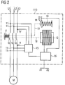
- the control magnet 12 After de-energizing the control magnet 12 is also checked by an evaluation device 15 by means of the electrodes 11 and 11 ', whether the contact bridges have exceeded the predetermined opening point.
- an evaluation device 15 To measure a voltage drop across the main contacts 10 are in the present embodiment for each current path L1-L3 two electrodes 11 and 11 ', once before the main contact 10 and once after the main contact 10, is provided. According to the invention, a voltage test on the main contacts 10 is then made by the evaluation device 15 via the electrodes 11 and 11 'after the main contacts 10 have been switched off. If the voltage drop across one of the main contacts 10 is too small, this is an indication that it has not opened far enough. That is, the opening distance traveled by the contact bridge when it is turned off has not exceeded the predetermined value, and there is a high probability of welding.
- the evaluation device 15 is connected via an unspecified connection with the control device 16. If such an error is detected by the evaluation device 15, it is forwarded to the control device 16, whereupon it interrupts at least one of the control lines.
- a trigger mechanism 14 is activated in the present embodiment, with a spring energy storage device 13 is unlatched.
- spring energy storage 13 may be, for example, already known of circuit breakers or compact starters switching locks.
- Such a switch lock then strikes by means of a mechanical operative connection 19 with high force on the non-opened main contacts 10 of the switching points of the switching device 110 in order to break the welded main contacts 10.
- the force of the spring accumulator 13 must be dimensioned correspondingly large.
- the spring accumulator 13 then either remains in the unlatched position and can not be reset, or the spring accumulator 13 has a mechanism by means of which the spring 13 again stretched and the trigger mechanism 14 can be latched again. Since the resetting of the mechanism 13 and 14 can only be done manually, a user is made aware of the accident and must accordingly, for example, by an exchange of the switching device 110, respond to it.
- only one current sensor per flow path can be provided. Then it is detected by the current measurement in each of the current paths, whether the opening point has been exceeded after switching off. If it has been detected on the basis of the current measurement that an exceeding of the opening point has not occurred, the further operation of the switching device is interrupted.
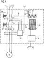
- FIG. 4 shows a third embodiment of the device according to the invention.
- a further switching element 39 ' is provided for interrupting the further operation, which is arranged in the individual current paths L1-L3 in series with the actual switching main contacts 30.
- the evaluation device 35 recognizes by means of the electrodes 31 and 31 'too low a voltage drop at this main contact 30.
- the evaluation device 35 causes a trigger mechanism 34 is activated and thus a spring energy storage 33 is unlatched.
- This spring energy storage 33 acts on the operative connection 39 on the switching element 39 'and opens it.
- the current paths L1-L3 are safely and independently of whether the main contacts 30 are open or closed, interrupted, and the further operation of the switching device 310 is prevented.
- FIG. 5 shows a fourth embodiment of the device according to the invention.
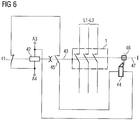
- the device has an auxiliary contact as Switch monitoring means 45 which is connected in series with a normally closed contact 41 of a control magnet 42 and electromagnetic drive 42.
- the normally closed contact 41 is, as shown, when you turn on, that is, upon energization of the control solenoid 42, opened.
- an actuator 44 is connected, which in the energized or energized state an opening means 46, such as a force accumulator or, as in FIG. 5 shown, can trigger a key lock.
- the control magnet 42 actuates a contact lever 43 via a drive lever 43, which can open and close the main contacts 1, wherein the main contacts 1 are closed in proper operation in the energized state of the control magnet 42, in which a contact load spring 40, the main contacts 1 closes.
- the auxiliary contact 45 is mechanically connected by means of an auxiliary contact slide 48 and the contact slide 43 with the main contacts 1, so that this is the switching state of the main contacts 1 to the auxiliary contact 45 "mirrored", that is transmitted.
- the mechanical connection is made such that in the case of welding at least one main contact 1 and the auxiliary contact 45 is closed or remains closed.
- the switch monitoring means 45 is brought into a first state when the main contacts 1 are closed when the device is switched on.
- the normally closed contact 41 is opened.
- the NC contact 41 is closed and the switch monitoring means 45 is opened.
- the switching monitoring means 45 remains after switching off in this first state, when at least one of the main contacts 1 is welded.
- the actuator 44 can now be energized.
- the actuator 44 may, for example, a Be lifting magnet, which then in the energized case, the breaking means 46, such as a spring memory, releases or the switching mechanism 46 triggers.
- the breaking means 46 such as a spring memory
- the switching voltage is usually “taken away", that is to say that the switching voltage for the electrical supply, in particular of the control magnet, is interrupted, it is advantageous if the switching voltage is reduced by means of an electrical storage element, e.g. a capacitor, is buffered.
- the capacitor voltage can be separated by a diode from the switching voltage.
- the switching device can be used particularly advantageously in a compact starter, in which both the contact opening during operational closing and a disconnection in the event of overcurrent are effected only by a main contact arrangement.
- FIG. 7 shows a fifth embodiment of the device according to the invention in detail.
- a switching mechanism 46 with an integrated spring memory as a force element for breaking a welded main contact 1 shown.
- the combined switching mechanism 46 acts in the case of a triggering via two rams 47, 51 which are mechanically in operative connection with each other, for example, directly on the movable contact bridge.
- a welded main contact 1 can be broken thereby.
- An actuator 44 as a trigger unit is connected by means of an exemplary rotatably mounted lever 52 to the switching mechanism 46.
- the actuator 44 is preferably a plunger anchor or a solenoid. To trigger the actuator 44 is supplied with power. This is done in an analogous manner as in the device according to FIG. 5 and FIG.
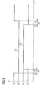
- the normally closed contact 41 and the release means 45 designed as a switching contact are actuated correctly with respect to one another in terms of time.
- opening the normally closed contact 41 opens in time before closing the release means 45 and when closing the normally closed contact 41 temporally after the opening of the release means 45 closes.
- the switching voltage for switching on and off of the switching device which is applied to the electrical terminals A3 and A4 for energizing the excitation coil 56 of the control magnet 42, are buffered via a diode for voltage decoupling and a downstream capacitor. Thereby is a sufficient electrical energy for triggering the force element 46 and the switching mechanism 46 upon removal of the switching voltage for switching off the device in case of failure available.
- the course of the magnetic field MF1 originating from the permanent magnets 68 is shown as a dot-dash line.
- the course of the resulting from the permanent magnet 68 magnetic field MF2 for the ON position of the electromagnetic drive 60 is located. In the latter case, there is no way with a low magnetic resistance for the magnetic field MF2 via the outer yoke 64, so that inevitably forms a stray magnetic field around the respective permanent magnet 68.
- a change in the magnetic flux, in particular outside the exciter coil 66 and in particular outside the inner yoke 65 of the electromagnetic drive 60 surrounding the exciter coil 66, can now be detected by means of a suitable measuring means.
- a particularly advantageous measuring coil 62 is wound around a leg of the outer yoke 64.
- a magnetic field sensor such as a Hall sensor, can be used. Starting from the OFF position, the magnetic flux MF1 flows through the measuring coil 62 stationary. If the armature 60 suddenly moves to the left in the ON position, the course of the magnetic flux also changes abruptly in such a way that a stray field MF2, as shown in FIG FIG.
- a particular advantage here is that even creeping wear of the drive mechanism of the electromagnetic drive 60 can be determined, which then lead to slower switching operations with a lower induction voltage u i .
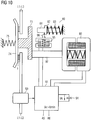
- the essential aspect of the device according to FIG. 10 is that an energy buffering occurs during operation, so that when you turn off and thus after removal of the power supply, the electrical supply of an evaluation and control unit can be guaranteed for a minimum time to optionally trigger a contact breaker and / or switch lock in the presence of a welded main contact or released.
- the control solenoid 92 shown actuates when actuated to turn on the switching device an armature 97 which is in a mechanical operative connection with a contact slide 73, which in turn acts on a contact bridge 74.
- the contact bridge 74 then bridges as a movable line piece, the fixed line sections of the current paths L1-L3.
- contact load spring 75 When switching on the control magnet 92 a biased in the off state of the switching device contact load spring 75 is released, which then presses the contact bridge 74 against the fixed line sections of the current paths L1-L3 and contacted.
- a welded main contact 1 and a switching mechanism can be controlled, which is designed to construct a welded main contact 1 usually can.
- Reference numeral 93 denotes means for detecting at least one welded main contact 1.
- the means are used according to the invention for detecting whether the movable contact bridge 74 of the at least one main contact 1 has exceeded an opening point after switching off.
- the means 93 is a current sensor, in particular a 3-fold current sensor for detecting the current flow in the main current paths L1-L3 of a 3-pole switching device.
- the current sensor 93 is connected via a connecting line for outputting a measured current value to the evaluation and control unit 91.
- the further operation of the switching device is interrupted when the opening point is not exceeded after a predetermined period of time.
- the release means 95 is, for example, an actuator in the form of a lifting or submersible magnet whose actuator armature 96 releases the release means 80 in the form of a spring accumulator.
- the inductance of the electromagnetic drive and thus the OFF position of the main contacts 1 could be determined via a metrological feedback. Or it could be via an auxiliary switch, such as a mirror contact according to IEC 60947-4-1, which is electrically connected to the evaluation and control unit 91, be determined whether the main contacts have opened 1. If it is determined that the main contacts 1 are not open, the energy store 94 is discharged via the release means 95.
- the current transformer (s) 93 could be dimensioned to be larger enough that the energy needed to operate the evaluation and control unit 91 and to trigger the release means 95 can be tapped off via the current transformers 93 from the main current paths L1-L3.
- FIG. 12 shows the seventh embodiment of the device according to the invention with closed main contacts 1.
- the excitation coil of the control magnet 72 via the electrical Connections A5, A6 energized.
- the armature 77 moves in the example of FIG. 12 to the right and relieves the contact slide 73. By this relief and by the relaxation of the preloaded contact load spring 75 now closes the contact bridge 74, the main contacts. 1
- the release means 85 for the contact breaker means 80 and at the same time a few moments thereafter the control magnet 72 is energized.
- the return spring of the release means 85 continues to be actively biased.
- the actuation delay of the control magnet 72 relative to the release means 85 can be done for example by mechanical damping means which act only for the switch-on.
- electrical damping means in the field circuit of the control magnet 72 can be used, such as a series connected to the excitation coil of the control magnet 72 throttle.
- Actuator armature 86 now does not release the contact break-up means 80, although armature 77 of control magnet 72 releases the stop or retention function as a result of the actuation which now begins.
- FIG. 12 shows due to the actuation of the armature 77 to the connector 76, a gap of a few millimeters, due to the new state of the Switching contacts 1 sets. This gap is reduced with the wear of the contact material.
- the end of the actuator armature 86 which lies opposite the locking tooth, now faces the connecting piece 76.
- the connecting piece 76 has a recess 78 in the region of the actuator armature 86, irrespective of whether the main contacts 1 are new or already worn.
- the recess 78 is dimensioned such that when the release means 86, ie the actuator designed as a lifting or submersible magnet, drops off, the contact opening means 80 is reliably released.
- the connecting piece 76 could also have a constant cross-section over its entire length corresponding to the dimensions of the connecting piece 76 in the end region.
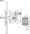
- FIG. 13 shows the seventh embodiment of the device according to the invention with a welded main contact 1 with not yet released Kunststoffetzbrechsch 80.
- the switching off of the control unit is usually carried out in that the switching voltage at the terminals A5 and A6 of the control magnet 72 is interrupted or removed.
- the switching voltage also feeds the release means 85 via the terminals A7 and A8, so that after removal of the switching voltage, this also drops.
- the exciter circuits of the control magnet 72 and the release means 85 may also be connected in series.
- the switching device now detects or checks whether the movable contact bridge 74 of the at least one main contact 1 has exceeded an opening point after switching off.
- the predetermined period of time may be, for example, 100 ms.
- the release means 85 preferably decelerates when it is switched off relative to the control magnet 72, so that the armature 77 can again assume the stop and retention function for the actuator armature 86 when it is switched off.
- the further operation of the switching device is interrupted after the predetermined period of time, when the anchor 77 is no longer actuated due to a welded main contact 1, so that he could still "catch” the already falling actuator anchor 86.
- the release agent 85 now drops completely, thereby releasing the contact breaker 80.
- the fall-off delay on turning off the actuator 85 may be e.g. take place by means of mechanical damping systems or by means of an electric freewheeling circuit with a freewheeling diode in the excitation circuit of the actuator 85.
- the freewheeling circuit maintains the magnetization of the magnetic circuit of the actuator 85 for the predetermined period of time.
- the exciter circuit of the control magnet 72 can be electrically attenuated by means of a relatively high-impedance resistor, so that very quickly the magnetic energy in the magnetic circuit of the control magnet 72 can be reduced.
- the spring force of the spring of the contact breaker 80 is dimensioned so that it can overcome the required Aufbrechkraft in addition to the opposite spring force of the contact load spring 75. Re-closing the main contacts 1 is no longer possible. The operation of the switching device is thus interrupted.
- the contact break-up means 80 may also include a mechanism, not shown, which allows to tension the released spring 83 and the release means 85 again. This reset of the mechanism can be done manually, for example.
Landscapes
- Physics & Mathematics (AREA)
- General Physics & Mathematics (AREA)
- Keying Circuit Devices (AREA)
- Driving Mechanisms And Operating Circuits Of Arc-Extinguishing High-Tension Switches (AREA)
Description
Die vorliegende Erfindung betrifft ein Verfahren zum sicheren Betrieb eines Schaltgerätes gemäß dem Oberbegriff des Anspruchs 1 sowie eine entsprechende Vorrichtung gemäß dem Oberbegriff des Anspruchs 20.The present invention relates to a method for the safe operation of a switching device according to the preamble of claim 1 and to a corresponding device according to the preamble of
Mit Schaltgeräten, insbesondere Niederspannungsschaltgeräten, lassen sich die Strombahnen zwischen einer elektrischen Versorgungseinrichtung und Verbrauchern und damit deren Betriebsströme schalten. Das heißt, indem vom Schaltgerät Strombahnen geöffnet und geschlossen werden, lassen sich die angeschlossenen Verbraucher sicher ein- und ausschalten.With switching devices, in particular low-voltage switchgear, the current paths between an electrical supply device and consumers and thus their operating currents can be switched. In other words, by opening and closing current paths from the switching device, the connected consumers can be reliably switched on and off.
Ein elektrisches Niederspannungsschaltgerät, wie beispielsweise ein Schütz, ein Leistungsschalter oder ein Kompaktstarter, weist zum Schalten der Strombahnen einen oder mehrere so genannte Hauptkontakte auf, die von einem oder auch mehreren Steuermagneten gesteuert werden können. Prinzipiell bestehen die Hauptkontakte dabei aus einer beweglichen Kontaktbrücke und festen Kontaktstücken, an die der Verbraucher und die Versorgungseinrichtung angeschlossen sind. Zum Schließen und Öffnen der Hauptkontakte wird ein entsprechendes Ein- oder Ausschaltsignal an die Steuermagnete gegeben, woraufhin diese mit ihrem Anker so auf die beweglichen Kontaktbrücken einwirken, dass die Kontaktbrücken eine Relativbewegung in Bezug auf die festen Kontaktstücke vollziehen und entweder die zu schaltende Strombahnen schließen oder öffnen.A low-voltage electrical switching device, such as a contactor, a circuit breaker or a compact starter, for switching the current paths on one or more so-called main contacts, which can be controlled by one or more control magnets. In principle, the main contacts consist of a movable contact bridge and fixed contact pieces, to which the consumer and the supply device are connected. To close and open the main contacts a corresponding on or off signal is given to the control magnets, whereupon they act with their armature so on the movable contact bridges that the contact bridges perform a relative movement with respect to the fixed contacts and either close the current paths to be switched or to open.
Zur besseren Kontaktierung zwischen den Kontaktstücken und den Kontaktbrücken sind an Stellen, an denen beide aufeinander treffen, entsprechend ausgebildete Kontaktflächen vorgesehen. Diese Kontaktflächen bestehen aus Materialien, wie beispielsweise Silberlegierungen, die an diesen Stellen sowohl auf die Kontaktbrücke als auch die Kontaktstücke aufgebracht sind und eine bestimmte Dicke aufweisen.For better contact between the contact pieces and the contact bridges are provided at points where both meet, correspondingly formed contact surfaces. These contact surfaces are made of materials such as silver alloys, both at these locations are applied to the contact bridge and the contact pieces and have a certain thickness.
Die Materialien der Kontaktflächen sind bei jedem der Schaltvorgänge einem Verschleiß unterworfen. Faktoren, die diesen Verschleiß beeinflussen können, sind:
- ▪ zunehmender Kontaktabbrand oder Kontaktabrieb mit steigender Anzahl von Ein- und Ausschaltvorgängen,
- ▪ zunehmende Verformungen,
- ▪ zunehmende Kontaktkorrosion durch Lichtbogeneinwirkung oder
- ▪ Umwelteinflüsse, wie beispielsweise Dämpfe oder Schwebstoffe usw.
- ▪ increasing contact erosion or contact wear with increasing number of on and off operations,
- ▪ increasing deformations,
- ▪ increasing contact corrosion due to arcing or
- ▪ Environmental influences, such as vapors or suspended matter, etc.
Als Folge davon werden die Betriebsströme nicht mehr sicher geschaltet, was zu Stromunterbrechungen, Kontaktaufheizungen oder zu Kontaktverschweißungen führen kann.As a result, the operating currents are no longer safely switched, which can lead to power interruptions, contact heating or contact welding.
So wird sich insbesondere mit zunehmendem Kontaktabbrand die Dicke der an den Kontaktflächen aufgebrachten Materialien verringern. Damit wird der Schaltweg zwischen den Kontaktflächen der Kontaktbrücke und der Kontaktstücke länger, was letztendlich die Kontaktkraft beim Schließen verringert. Als Folge davon werden mit zunehmender Anzahl von Schaltvorgängen die Kontakte nicht mehr richtig schließen. Durch die daraus resultierenden Stromunterbrechungen oder aber auch durch ein verstärktes Einschaltprellen kann es dann zu einer Kontaktaufheizung und damit zu einem zunehmenden Aufschmelzen des Kontaktmaterials kommen, was dann wiederum zu einem Verschweißen der Kontaktflächen der Hauptkontakte führen kann.Thus, in particular with increasing contact erosion, the thickness of the materials applied to the contact surfaces will decrease. Thus, the switching path between the contact surfaces of the contact bridge and the contact pieces is longer, which ultimately reduces the contact force when closing. As a result, with increasing number of switching operations, the contacts will not close properly. Due to the resulting power interruptions or else by an increased switch-on bounce, it can then come to a contact heating and thus to an increasing melting of the contact material, which in turn can lead to a welding of the contact surfaces of the main contacts.
Ist ein Hauptkontakt des Schaltgerätes verschlissen oder sogar verschweißt, kann das Schaltgerät den Verbraucher nicht mehr sicher ausschalten. So wird gerade bei einem verschweißten Kontakt trotz des Ausschaltsignals zumindest die Strombahn mit dem verschweißten Hauptkontakt weiter strom- beziehungsweise spannungsführend bleiben, und damit der Verbraucher nicht vollständig von der Versorgungseinrichtung getrennt. Da somit der Verbraucher in einem nicht sicheren Zustand verbleibt, stellt das Schaltgerät eine potentielle Fehlerquelle dar.If a main contact of the switching device is worn or even welded, the switching device can no longer switch off the load safely. This is how a welded one becomes Contact despite the turn-off signal at least the current path with the welded main contact continue to remain energized or live, and thus the consumer is not completely disconnected from the supply device. Since the consumer thus remains in a non-safe state, the switching device represents a potential source of error.
Dadurch kann beispielsweise bei Kompaktstartern nach der IEC 60 947-6-2, bei denen ein zusätzlicher Schutzmechanismus auf die selben Hauptkontakte wirkt wie der Steuermagnet beim betriebsmäßigen Schalten, die Schutzfunktion blockiert werden.As a result, for example, in compact starters according to IEC 60 947-6-2, in which an additional protection mechanism acts on the same main contacts as the control magnet during operational switching, the protective function can be blocked.
Zum sicheren Betrieb von Schaltgeräten und damit zum Schutz des Verbrauchers und der elektrischen Anlage sind deshalb solche Fehlerquellen zu vermeiden.For safe operation of switching devices and thus to protect the consumer and the electrical system such sources of error should be avoided.
Aus dem Dokument
- Erkennen, ob die bewegliche Kontaktbrücke des zumindest einen Hauptkontaktes nach dem Ausschalten einen Öffnungspunkt überschritten hat,
- Unterbrechung des weiteren Betriebs des Schaltgerätes, wenn nach einer vorgegebenen Zeitdauer der Öffnungspunkt nicht überschritten ist.
- Detecting whether the movable contact bridge of the at least one main contact has exceeded an opening point after switching off,
- Interruption of the further operation of the switching device, if after a predetermined period of time the opening point is not exceeded.
Ein ähnlicher Gegenstand ist auch in den Dokumenten
Aus dem Dokument
Nachteilig bei diesen Gegenständen ist, dass bei einem verschweißten Hauptkontakt das zugrunde liegende Schaltgerät, wie oben schon erwähnt, den Verbraucher nicht sicher ausschaltet. Es bleibt zumindest die Strombahn mit dem verschweißten Hauptkontakt weiter strom- beziehungsweise spannungsführend, so dass der Verbraucher nicht vollständig von der Versorgungseinrichtung getrennt ist. Das Schaltgerät stellt damit eine potentielle Fehlerquelle dar.A disadvantage of these objects is that when a welded main contact the underlying switching device, as mentioned above, the consumer does not turn off safely. It remains at least the current path with the welded main contact further current or live, so that the consumer is not completely separated from the supply device. The switching device thus represents a potential source of error.
Aufgabe der vorliegenden Erfindung ist es, solche potentiellen Fehlerquellen zu erkennen und entsprechend darauf zu reagieren.The object of the present invention is to identify such potential sources of error and to react accordingly.
Diese Aufgabe wird gelöst durch das Verfahren mit den Merkmalen des Anspruchs 1 sowie durch die Vorrichtung mit den Merkmalen des Anspruchs 20. Im Anspruch 39 ist ein geeignetes Schaltgerät zur Durchführung des Verfahrens angegeben. Im Anspruch 40 ist ein geeignetes Schaltgerät mit der erfindungsgemäßen Vorrichtung angegeben. In den Untersprüchen 2 bis 19, 21 bis 38 und 41 sind Verfahrens- und Vorrichtungsvarianten enthalten.This object is achieved by the method having the features of claim 1 and by the device having the features of
Die vorliegende Erfindung ermöglicht so mit geringem Aufwand, eine Kontaktverschweißung beim Ausschalten und damit einen nicht mehr sicheren Betrieb des Schaltgerätes zu erkennen und entsprechend darauf zu reagieren.The present invention thus makes it possible, with little effort, to detect contact welding when it is turned off and thus to prevent operation of the switching device that is no longer safe, and to react accordingly.
Erfindungsgemäß wird dazu im Betrieb eines Schaltgerätes insbesondere beim Ausschalten erkannt, ob die bewegliche Kontaktbrücke des zumindest einen Hauptkontaktes einen Öffnungspunkt überschreitet. Der weitere Betrieb des Schaltgerätes wird unterbrochen, und zwar insbesondere auch dadurch, dass der Hauptkontakt aufgebrochen wird, wenn nach einer vorgegebenen Zeitdauer der Öffnungspunkt nicht überschritten ist.According to the invention, during operation of a switching device, in particular when switching off, it is detected whether the movable contact bridge of the at least one main contact exceeds an opening point. The further operation of the switching device is interrupted, and in particular also by the fact that the main contact is broken when, after a predetermined period of time, the opening point is not exceeded.
Der vorgegebene Öffnungspunkt entspricht dabei einem zuvor ermittelten Öffnungsweg der Kontaktbrücke, bei dem diese gerade noch mit den Kontaktstücken in Verbindung steht. Wird dann nach dem Ausschalten, das heißt nach dem gewollten Öffnen des zumindest einen Hauptkontaktes, ein Öffnungsweg ermittelt, der kleiner ist als dieser vorgegebene Öffnungspunkt, so kann davon ausgegangen werden, dass eine Verschweißung und damit ein nicht sicherer Betrieb des Schaltgerätes vorliegt. Wird das Auftreten eines solchen nicht sicheren Betriebsfalls im laufenden Betrieb überwacht und erkannt, kann rechtzeitig der weitere Betrieb des Schaltgerätes unterbunden werden.The predetermined opening point corresponds to a previously determined opening path of the contact bridge, in which this is just in contact with the contact pieces. If, after switching off, that is to say after the intentional opening of the at least one main contact, an opening path is determined which is smaller than this predetermined opening point, then it can be assumed that there is welding and thus unsafe operation of the switching device. If the occurrence of such a non-safe operating case is monitored and detected during operation, further operation of the switching device can be prevented in good time.
Somit ist mit dem erfindungsgemäßen Verfahren und der erfindungsgemäßen Vorrichtung der sichere Betrieb eines Schaltgerätes, wie zum Beispiel eines Schützes, eines Leistungsschalters oder eines Kompaktabzweig, und insbesondere der sichere Betrieb eines dreipoligen Schaltgerätes gewährleistet. Der sichere Betrieb ist insbesondere dadurch gewährleistet, weil in einem betreffenden Fall mit Sicherheit dafür gesorgt wird, dass keine Strombahn strom- beziehungsweise spannungsführend bleibt.Thus, with the method and the device according to the invention the safe operation of a switching device, such as a contactor, a circuit breaker or a compact feeder, and in particular the safe operation of a three-pole switching device is guaranteed. Safe operation is ensured, in particular, because in a particular case it is ensured with certainty that no current path remains energized or live.
In einer erfindungsgemäßen Ausgestaltung wird das Überschreiten des Öffnungspunktes durch eine Messung eines Stroms in einer vom Hauptkontakt zu schaltenden Strombahn erkannt, wobei der Öffnungspunkt nicht überschritten ist, wenn der gemessene Strom größer als ein nach dem Ausschalten vorgesehener Strom ist.In an embodiment according to the invention, the exceeding of the opening point is detected by measuring a current in a current path to be switched by the main contact, the opening point not being exceeded if the measured current is greater than a current provided after switching off.
Das Überschreiten des Öffnungspunktes kann auch durch eine Messung eines Spannungsabfalls über einen Hauptkontakt erkannt werden, wobei der Öffnungspunkt nicht überschritten ist, wenn der Spannungsabfall kleiner ist als ein nach dem Ausschalten vorgesehener Spannungsabfall.Exceeding the opening point can also be detected by measuring a voltage drop across a main contact , wherein the opening point is not exceeded when the voltage drop is smaller than a voltage drop provided after switching off.
In einer weiteren Ausgestaltung wird das Überschreiten des Öffnungspunktes durch eine Messung einer Induktivität des Steuermagneten erkannt, wobei der Öffnungspunkt nicht überschritten ist, wenn die Induktivität nach dem Ausschalten einen Wert aufweist, der nicht dem vorgegebenen Wert nach dem Öffnen im Vergleich zum ordnungsgemäßen Betrieb entspricht.In a further embodiment, the exceeding of the opening point is detected by a measurement of an inductance of the control magnet, wherein the opening point is not exceeded, if the inductance after switching off has a value that does not correspond to the predetermined value after opening compared to the proper operation.
Weiterhin kann der Öffnungspunkt durch einen Zustand von mit der Kontaktbrücke in Wirkverbindung stehenden Mitteln erkannt werden, wobei der erkannte Öffnungspunkt nicht überschritten ist, wenn diese Mittel nach dem Ausschalten in diesem Zustand verbleiben, der nicht dem vorgegebenen Zustand nach dem Öffnen entspricht. Dies ist z.B. bei einer Verschweißung zumindest eines Hauptkontaktes der Fall.Furthermore, the opening point can be detected by a state of means operatively connected to the contact bridge, wherein the detected opening point is not exceeded, if these means remain after switching off in this state, which does not correspond to the predetermined state after opening. This is e.g. in a welding at least one main contact of the case.
In einer weiteren erfindungsgemäßen Ausgestaltung wird beim Einschalten oder zum Einschalten eines Steuermagneten ein Hilfskontakt geschlossen, wobei beim Einschalten des Steuermagneten dann ein Öffnerkontakt geschlossen wird. Ein Freigabemittel, welches in Reihe zu den Schaltkontakten geschaltet ist, löst dann das Kontaktaufbrechmittel aus, wenn der Hilfskontakt beim Ausschalten im geschlossenen Zustand verbleibt bzw. verblieben ist. Auch in diesem Fall ist von einer Verschweißung oder Verklebung zumindest eines der Hauptkontakte auszugehen.In a further embodiment of the invention, an auxiliary contact is closed when switching on or to turn on a control magnet, wherein when switching on the control magnet then a normally closed contact is closed. A release means, which is connected in series with the switching contacts, then triggers the contact breaking means, if the auxiliary contact remains in the closed state when switched off or remains. In this case as well, at least one of the main contacts should be assumed to be welded or adhesively bonded.
Insbesondere sind die Schaltkontakte so ausgeführt, dass der Hilfskontakt beim Einschalten vor dem Öffnerkontakt schließt und dass der Öffnerkontakt beim Ausschalten vor dem Hilfskontakt schließt.In particular, the switching contacts are designed so that the auxiliary contact closes before switching on the normally closed contact and that the normally closed contact closes when switching off before the auxiliary contact.
In einer weiteren erfindungsgemäßen Ausgestaltung wird bei einer Schaltbetätigung eine magnetische Flussänderung des magnetischen Kreises des Steuermagneten gemessen, wobei der Öffnungspunkt überschritten ist, wenn beim Ausschalten des Steuermagneten die magnetische Flussänderung einen vorgegebenen Vergleichswert überschritten hat. Vorzugsweise wird die magnetische Flussänderung mittels einer Induktionsspule gemessen.In a further embodiment of the invention, a magnetic flux change of the magnetic circuit of the control magnet is measured at a switching operation, wherein the opening point is exceeded, when the magnetic flux change has exceeded a predetermined comparison value when switching off the control magnet. Preferably, the measured magnetic flux change by means of an induction coil.
Gemäß einer weiteren erfindungsgemäßen Ausgestaltung wird die elektrische Versorgung für eine Auswerte- und Steuereinheit des Schaltgerätes mittels eines elektrischen Speicherelements, wie z.B. mittels eines Kondensators, einer elektrischen Spule oder eines Akkumulators, für eine Mindestzeit aufrechterhalten, um ein Vorliegen eines verschweißten Hauptkontakts messtechnisch zu prüfen bzw. zu erkennen und um ggf. das Kontaktaufbrechmittel und/oder ein Schaltschloss anzusteuern bzw. freizugeben.According to a further embodiment of the invention, the electrical supply for an evaluation and control unit of the switching device by means of an electrical storage element, such. by means of a capacitor, an electric coil or a rechargeable battery, maintained for a minimum time to metrologically check or detect the presence of a welded main contact and, if necessary, to control the contact breaker and / or a switch lock or release.
Insbesondere wird der Steuermagnet erst bei Vorliegen eines Schaltbefehls zum Betätigen zumindest eines Hauptkontakts erregt, wenn das elektrische Speicherelement einen Mindestladezustand erreicht hat. Der Mindestladezustand ist dabei so bemessen, dass nach dem Ausschalten des Steuergerätes und insbesondere nach Wegnahme der Schaltspannung zur elektrischen Erregung des Steuermagneten des Schaltgerätes die Auswerte- und Steuereinheit elektrisch versorgt und gegebenenfalls noch den Auslösevorgang starten kann.In particular, the control magnet is energized only in the presence of a switching command for actuating at least one main contact when the electric storage element has reached a minimum state of charge. The minimum state of charge is dimensioned such that after switching off the control unit and in particular after removal of the switching voltage for electrical excitation of the control magnet of the switching device, the evaluation and control unit electrically powered and optionally can still start the tripping operation.
In einer weiteren Ausgestaltung der Erfindung wird im eingeschalteten Zustand des Steuermagneten aktiv ein Freigabemittel in einem erregten Zustand gehalten, um die Auslösung des Kontaktaufbrechmittels zu verhindern. Beim Ausschalten werden dann das Freigabemittel und der Steuermagnet entregt, wobei dann ein Anker oder eine mit dem Anker in einer mechanischen Wirkverbindung stehende Komponente des Steuermagneten die Auslösung des Freigabemittels verhindert.In a further embodiment of the invention, a release agent is kept in an energized state actively in the activated state of the control magnet to prevent the triggering of the contact breaking means. When you turn off the release agent and the control solenoid are then de-energized, in which case an anchor or with the armature in a mechanically operative connection component of the control magnet prevents the release of the release agent.
So kann z.B. eine vorgespannte Feder eines Federspeichers durch das Freigabemittel daran gehindert werden, sich zu entspannen. Das Freigabemittel weist dabei auch ein Rückstellmittel auf, wie z.B. eine Rückstellfeder, welche nach Wegnahme der Energiezufuhr zur Aufrechterhaltung des aktiv erregten Zustandes dieses sicher in einen passiven entregten Zustand überführt. Die durch das Rückstellmittel freiwerdende Energie gibt dann die um ein Vielfaches größere gespeicherte Energie im Kontaktaufbrechmittel frei. Diese gespeicherte Energie wird nach Freigabe in einen mechanischen Impuls umgewandelt, der letztlich den verschweißten Hauptkontakt aufbricht.For example, a preloaded spring of a spring accumulator can be prevented by the release agent from relaxing. The release means also has a return means, such as a return spring, which after removal of the power supply to maintain the active state excited this safely in a passive de-energized state transferred. The energy released by the return means then releases the much larger stored energy in the contact breaker. Once stored, this stored energy is converted into a mechanical impulse that ultimately breaks up the welded main contact.
Insbesondere wird beim Einschalten das Freigabemittel zeitlich vor dem Steuermagneten entregt. Zudem wird beim Ausschalten der Steuermagnet zeitlich vor dem Freigabemittel entregt. Vorzugsweise ist das Freigabemittel ein Hub- oder Tauchmagnet. Das Kontaktaufbrechmittel weist im Besonderen einen Federspeicher, wie z.B. eine zylindrische Druckfeder, auf.In particular, the release means is de-energized in time before switching on the control magnet when switching on. Moreover, when the control magnet is switched off, it is de-energized before the release agent. Preferably, the release means is a lifting or submersible magnet. In particular, the contact breaker means includes a spring accumulator, such as a spring breaker. a cylindrical compression spring, on.
Des Weiteren wird der weitere Schaltbetrieb unterbrochen, indem ein in Reihe mit dem Hauptkontakt in der Strombahn angeordnetes Schaltelement geöffnet wird.Furthermore, the further switching operation is interrupted by opening a switching element arranged in series with the main contact in the current path.
Schließlich wird der weitere Schaltbetrieb unterbrochen, indem zumindest eine Steuerleitung zum Steuern des Steuermagneten unterbrochen wird.Finally, the further switching operation is interrupted by at least one control line for controlling the control magnet is interrupted.
Weitere vorteilhafte Ausführungen und bevorzugte Weiterbildungen der Erfindung sind den Unteransprüchen zu entnehmen.Further advantageous embodiments and preferred developments of the invention can be found in the dependent claims.
Das Verfahren zur Bestimmung der Restlebensdauer von Schaltkontakten kann dabei zum einen in der zeitlichen Erfassung vorgegebener diskreter Positionen des Magnetankers des Steuermagneten oder auch mit dem Anker in Wirkverbindung stehenden Komponenten und in der Bestimmung der Geschwindigkeit und der mittleren Beschleunigung des Ankers oder dieser Komponente bestehen, an der die Positionsmessung vorgenommen wird. Zum anderen kann es in der Messung der Einschaltzeitpunkte der Schaltkontakte während ihrer Schließbewegung bestehen.The method for determining the remaining service life of switching contacts can consist of the temporal detection of predetermined discrete positions of the magnet armature of the control magnet or of components operatively connected to the armature and determination of the velocity and average acceleration of the armature or component the position measurement is made. On the other hand, it may consist in the measurement of the switch-on of the switching contacts during their closing movement.
So werden zur Bestimmung der Restlebensdauer wenigstens vier Zeitpunkte erfasst, von denen einer den Kontaktschließzeitpunkt darstellt und von denen die anderen die Positionszeitpunkte eines oder mehrerer Positionsgeber darstellen. Wenigstens zwei dieser Zeitpunkte können dabei Zeitwerte zweier nah benachbarter Positionen sein, aus welchen dann ein Geschwindigkeitswert des bewegten Bauteiles ableitbar ist. Da das überwachte Bauteil während des Einschaltvorganges im Allgemeinen eine beschleunigte Bewegung ausführt, wird neben diesem so ermittelten Geschwindigkeitswert für wenigstens ein Zeitintervall ein mittlerer Wert einer konstanten Beschleunigung bestimmt. Aus den ermittelten Werten der Geschwindigkeit und der Beschleunigung, sowie aus den Relativpositionen der Positionsgeber zueinander und ihrer Positionszeitpunkte, kann für den Kontaktschließzeitpunkt durch eine einfache mathematische Beziehung die Position des schließenden Kontaktes bestimmt werden. Aus dieser Position lässt sich bestimmen, ob die bewegliche Kontaktbrücke des zumindest einen Hauptkontaktes insbesondere nach dem Ausschalten einen Öffnungspunkt überschritten hat oder nicht. Wird nach einer vorgegebenen Zeitdauer dieser Öffnungspunkt nicht erreicht, so wird der weitere Betrieb des Schaltgerätes unterbrochen.Thus, at least four points in time are determined to determine the remaining lifetime, one of which represents the contact closure time and of which the other the position times represent one or more position encoder. At least two of these times can be time values of two closely adjacent positions, from which a speed value of the moving component can then be derived. Since the monitored component generally performs an accelerated movement during the switch-on process, an average value of a constant acceleration is determined for at least one time interval in addition to this speed value determined in this way. From the determined values of the speed and the acceleration, as well as from the relative positions of the position sensors to each other and their position times, the position of the closing contact can be determined for the contact closure time by a simple mathematical relationship. From this position can be determined whether the movable contact bridge of the at least one main contact has exceeded an opening point, in particular after switching off or not. If after a predetermined period of time this opening point is not reached, the further operation of the switching device is interrupted.
Für geschwindigkeitsregelbare Schaltgeräte, insbesondere Schütze, die aus einem regelbaren, magnetischen Antrieb bestehen, kann so die mit dem Positionssensor gemessene Geschwindigkeit v genutzt werden, um den Antrieb iterativ auf eine vorgegebene Geschwindigkeit einzustellen oder um die Geschwindigkeit auf ein vorgegebenes Intervall zu beschränken. Dazu werden die Steuerparameter mit jeder Einschaltung des Antriebes mit einem vorgegebenen Parameterschritt in Richtung höhere Geschwindigkeit gestellt, solange die Geschwindigkeit kleiner ist als der Sollwert oder unterhalb des Sollbereiches liegt. Alternativ können die Steuerparameter mit jeder Einschaltung des Antriebes mit einem vorgegebenen Parameterschritt in Richtung kleinere Geschwindigkeit gestellt werden, solange die Geschwindigkeit größer ist als der Sollwert oder oberhalb des Sollbereiches liegt. Damit wird erreicht, dass die Kontakte nach erreichter Geschwindigkeitseinstellung mit der vorgegebenen Geschwindigkeit schließen.For speed-controllable switching devices, in particular contactors, which consist of a controllable, magnetic drive, so the measured speed with the position sensor can be used v to set the drive iteratively to a predetermined speed or to limit the speed to a predetermined interval. For this purpose, the control parameters with each switching on of the drive with a predetermined parameter step in the direction of higher speed, as long as the speed is less than the setpoint or below the target range. Alternatively, each time the drive is switched on, the control parameters can be set in the direction of a lower speed with a predetermined parameter step as long as the speed is greater than the setpoint value or above the setpoint range. This ensures that the contacts close after reaching the speed setting with the specified speed.
Eine weitere Möglichkeit gemäß der Erfindung besteht in der Erfassung der Bewegkontaktmasse mithilfe eines Kraftsensors. Dieser misst den Kraftstoß, der vom ausschaltenden Antrieb auf den Bewegkontakt übertragen wird. Da die Öffnungsgeschwindigkeit des Bewegkontaktes vom Masseverlust näherungsweise unabhängig ist, erhält man einen zur Masse proportionalen Impuls des Bewegkontaktes und daher einen zur Masse proportionalen Kraftstoß am Kraftsensor. Dieser Kraftstoß wird über einen vorgegebenen Zeitabschnitt nach dem Ausschaltkommando des Antriebs als Kraft-Zeit-Integral ermittelt und erfährt bei einem Materialverlust von beispielsweise 10% eine Abnahme von ebenfalls etwa 10%. Der Mindestwert der verbliebenen Masse an Kontaktmaterial ist hierbei mit einem korrespondierenden Mindestwert der Bewegkontaktmasse verknüpft, welcher nach Erfahrungswerten den Verlust an Kontaktträgermaterial mit einbezieht.Another possibility according to the invention is the detection of the moving contact mass by means of a force sensor. This measures the force impulse, which is transferred from the switching off drive to the moving contact. Since the opening speed of the moving contact is approximately independent of the loss of mass, one obtains a pulse of the moving contact which is proportional to the mass and therefore a force impulse proportional to the mass on the force sensor. This power surge is determined over a given period of time after the Ausschaltkommando the drive as a force-time integral and undergoes a decrease of about 10%, for example, with a loss of material, for example, 10%. The minimum value of the remaining mass of contact material is in this case linked to a corresponding minimum value of the moving contact mass, which according to empirical values includes the loss of contact carrier material.
Bei einem Magnetantrieb als Schaltgeräteantrieb kann der Kraftsensor zwischen dem Magnetanker und dem mechanischen Koppelglied, das den Bewegkontakt öffnet, angeordnet sein. Die elektrische Hilfsenergie zu dem Kraftsensor und dessen Messsignal zur Überwachungseinheit können über federnde Kontaktglieder geleitet sein.In the case of a magnetic drive as switching device drive, the force sensor can be arranged between the magnet armature and the mechanical coupling member which opens the moving contact. The auxiliary electrical energy to the force sensor and its measurement signal to the monitoring unit can be passed through resilient contact members.
Durch Auswertung des entsprechenden Kraftwertsignals kann somit gemäß der Erfindung erkannt werden, ob die bewegliche Kontaktbrücke des zumindest einen Hauptkontaktes insbesondere beim Ausschalten einen Öffnungspunkt überschritten hat. Weicht das Kraftwertsignal von einem vorgegebenen Kraftvergleichswert ab, so wird der weitere Betrieb des Schaltgerätes nach einer vorgegebenen Zeitdauer unterbrochen.By evaluating the corresponding force value signal can thus be detected according to the invention, whether the movable contact bridge of at least one main contact has exceeded an opening point in particular when switching off. If the force value signal deviates from a predetermined force comparison value, the further operation of the switching device is interrupted after a predetermined period of time.
Eine jeweilige Schaltposition des Ankers bzw. eines mit dem Anker in einer Wirkverbindung stehenden Komponenten kann z.B. mittels Kapazitätsmessung eines Messkondensators erfolgen. Der Messkondensator weist dabei zwei Kondensatorplatten auf, die sich entsprechend der Ankerbewegung relativ zu einander bewegen können. Der dadurch resultierende unterschiedliche Kondensatorplattenabstand für zu einer Veränderung der Kapazität des Messkondensators. Zur Bestimmung der Kapazitätszunahme kann mit einer Konstantspannungsquelle ein Ladestrompuls in den Messkondensator eingespeist werden. Dabei ist das Strom-Zeit-Integral des Ladestrompulses proportional zur Kapazitätsänderung und es kann mit den übrigen Kondensatordaten daraus der aktuelle Kontaktdurchdruck berechnet werden. Erreicht der Durchdruckwert einen Mindestwert, so wird das Schaltgerät von der Überwachungseinheit außer Betrieb gesetzt.A respective switching position of the armature or a component in operative connection with the armature can be effected, for example, by means of capacitance measurement of a measuring capacitor. The measuring capacitor has two capacitor plates, which can move relative to each other according to the armature movement. The resulting different Capacitor plate spacing for to change the capacitance of the measuring capacitor. To determine the increase in capacitance, a charging current pulse can be fed into the measuring capacitor with a constant voltage source. Here, the current-time integral of the charging current pulse is proportional to the capacitance change and it can be calculated with the other capacitor data from the current contact pressure. If the pressure value reaches a minimum value, the switching device is put out of operation by the monitoring unit.
Mittels der Kapazitätsänderung kann alternativ erkannt werden, ob die bewegliche Kontaktbrücke des zumindest einen Hauptkontaktes, die mit dem Anker in einer mechanischen Wirkverbindung steht, insbesondere nach dem Ausschalten einen Öffnungspunkt überschritten hat. Der Öffnungspunkt lässt sich dabei rechnerisch aus der Kapazitätsänderung bzw. aus dem Zeitwert ermitteln, der benötigt wird, um den Messkondensator zu laden. Überschreitet dieser Zeitwert einen vorgegebenen Wert, so muss der Messkondensatorplattenabstand sehr klein sein, und es ist davon auszugehen, dass sich der Anker und die damit verbundene Kontaktbrücke nicht mehr geöffnet hat. In diesem Fall ist davon auszugehen, dass eine Verschweißung zumindest eines Hauptkontaktes vorliegt. Der weitere Betrieb des Schaltgerätes wird dann unterbrochen.By means of the change in capacitance, it can alternatively be detected whether the movable contact bridge of the at least one main contact, which is in a mechanically operative connection with the armature, has exceeded an opening point, in particular after switching off. The opening point can be determined by calculation from the change in capacitance or from the time value that is required to charge the measuring capacitor. If this time value exceeds a predetermined value, the measuring capacitor plate spacing must be very small, and it can be assumed that the armature and the contact bridge connected thereto no longer has opened. In this case, it can be assumed that there is a welding of at least one main contact. The further operation of the switching device is then interrupted.
Beim Ausschalten hängt die Kontaktöffnungsgeschwindigkeit v empfindlich vom Kontaktdurchdruck D ab, da z.B. bei einem Magnetantrieb sich der Magnetanker und die angekoppelten mechanischen Bauteile aus der Ruhelage (Schließstellung) mit etwa konstanter Beschleunigung b bewegen. Für die Auftreffgeschwindigkeit des Antriebs auf den Bewegkontakt erhält man die Beziehung: 
Die Erfassung der Geschwindigkeit kann durch den zuvor beschriebenen Messkondensator erfolgen. Da die Öffnungsbewegung des Magnetankers eine Abnahme des Kondensator-Plattenabstandes bewirkt, und dies zu einem Strom i der Konstantspannungsquelle U auf den Messkondensator führt, ergibt sich für den Kontaktdurchdruck D die Beziehung:
t = tö, wobei tö der Zeitpunkt des Öffnungsstoßes auf den Bewegkontakt ist.The detection of the speed can be done by the measuring capacitor described above. Because the opening movement of the armature causes a decrease in the capacitor-plate spacing, and this leads to a current i of the constant voltage source U on the measuring capacitor, the contact pressure D is the relationship:
t = tö, where to is the time of the opening shock on the moving contact.
Somit kann der Kontaktdurchdruck D nach folgender Gleichung bestimmt werden:
D = i(t)2*(2b)-1*(d2/(εAU))2, woraus sich wiederum näherungsweise D ∼ i(t)2 und damit ∼ imax2 ergibt.Thus, the contact pressure D can be determined according to the following equation:
D = i (t) 2 * (2b) -1 * (d 2 / (εAU)) 2 , which in turn yields approximately D ~ i (t) 2 and thus ~ imax 2 .
In der Gleichung sind dabei die Ankerbeschleunigung b, der Plattenabstand d zum Zeitpunkt des Öffnungsstoßes, die Plattenfläche A, die Konstantspannung U und der Kondensatorstrom imax zum Zeitpunkt tö enthalten. Unterschreitet imax2 einen vorgegebenen Mindestwert, so wird das Schaltgerät von der Überwachungseinheit außer Betrieb gesetzt.The equation includes the armature acceleration b, the plate spacing d at the time of the opening shock, the plate area A, the constant voltage U and the capacitor current imax at the time t0. If imax 2 falls below a predetermined minimum value, then the switching device is put out of operation by the monitoring unit.
In allen Fällen, in denen die Überwachungseinheit das Schaltgerät außer Betrieb setzt, kann die das Entscheidungskriterium liefernde Messgröße zuvor über eine vorgegebene Anzahl von Messungen gemittelt werden.In all cases in which the monitoring unit deactivates the switching device, the measured variable which supplies the decision criterion can be averaged over a predetermined number of measurements beforehand.
Die Schließgeschwindigkeit des Bewegkontaktes ist wegen der dominierenden bewegten Masse des Schaltgeräteantriebes (Magnetanker) von dem verschleißbedingten Masseverlust des Bewegkontaktes praktisch unabhängig. Unter sonst gleichen Verhältnissen ist die Schließgeschwindigkeit daher immer dieselbe. Allerdings wird die Schließgeschwindigkeit mit abnehmendem Kontaktdurchdruck zunehmen, da die Magnetkräfte bei kleinem Ankerluftspalt eine erhebliche Größe erreichen und den Anker deutlich beschleunigen.The closing speed of the moving contact is practically independent of the wear-related loss of mass of the moving contact because of the dominant moving mass of the switching device drive (armature). Under otherwise identical conditions, the closing speed is therefore always the same. However, the closing speed will increase with decreasing contact pressure, since the magnetic forces reach a considerable size with a small armature air gap and significantly accelerate the anchor.
Die Masseänderung des Bewegkontaktes spielt im Feder-Masse-System von Bewegkontaktmasse und Kontaktkraft beim Kontaktprellen eine Rolle und kann durch Zeitmessung des Prellvorganges näherungsweise bestimmt werden. Die eventuelle Abnahme der Kontaktkraft mit dem Kontaktabbrand kann bei der Auswertung des Kontaktprellens berücksichtigt werden.The mass change of the moving contact plays in the spring-mass system of Bewegkontaktmasse and contact force during contact bounce a role and can be approximated by timing the bounce process. The possible decrease in the contact force with the contact erosion can be taken into account in the evaluation of the contact bounce.
Unter der Annahme, dass beim ersten Prellsprung ein bestimmter Anteil α an kinetischer Energie für die Kontaktabhebung verfügbar ist, folgt für die Kontakt-Abhebegeschwindigkeit vK,A aus der Kontakt-Schließgeschwindigkeit vK,S : 


FK ist hierbei die Kontaktkraft und T die Abhebedauer der ersten Prellabhebung.F K is the contact force and T is the takeoff time of the first bounce lift.
Durch Mittelung über eine vorgegebene Anzahl von gemessenen Prellzeiten können zufällige Schwankungen ausreichend unterdrückt und eine repräsentative Abhebedauer bestimmt werden. Für die Zeitmessung kann das Kontaktspannungssignal nach dem ersten Schließen der Kontakte ausgewertet werden.By averaging over a predetermined number of measured bounce times, random fluctuations can be sufficiently suppressed and a representative liftoff duration can be determined. For the time measurement, the contact voltage signal can be evaluated after the first closing of the contacts.
Für eine genauere Auswertung des Masseverlustes ΔmK wird der aktuelle Wert der Kontakt-Schließgeschwindigkeit vK,S herangezogen. Dieser kann mit einem Messkondensator bestimmt werden. Zu dem Kontakt-Schließzeitpunkt t = ts fließt aus der Konstantspannungsquelle U der Strom 
Die Ankerschließgeschwindigkeit v des Magnetantriebes nach der Kontaktberührung hängt empfindlich vom Kontaktdurchdruck D ab, da auf den Magnetanker mit kleiner werdendem Ankerluftspalt immer größere Magnetkräfte einwirken. Man kann den Wert der Ankerschließgeschwindigkeit vK,S zum Zeitpunkt ts der Kontaktberührung als grobes Maß für den Kontaktverschleiß heranziehen. Überschreitet v(ts) einen vorgegebenen Wert, so wird dies mit dem Erreichen des Mindestdurchdruckes gleichgesetzt. Die Geschwindigkeit (Betrag) wird, wie vorausgehend beschrieben, an einem geeigneten Messkondensator bestimmt, nämlich durch: 
Die Erfindung sowie vorteilhafte Ausführungen derselben werden im Weiteren anhand der nachfolgenden Figuren näher beschrieben. Es zeigen:
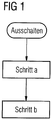
- FIG 1
- ein vereinfachtes Flussdiagramm des erfindungsgemäßen Verfahrens,
- FIG 2
- eine erste Ausführungsform der erfindungsgemäßen Vorrichtung,
- FIG 3
- eine zweite Ausführungsform der erfindungsgemäßen Vorrichtung,
- FIG 4
- eine dritte Ausführungsform der erfindungsgemäßen Vorrichtung.
- FIG 5
- eine vierte Ausführungsform der erfindungsgemäßen Vorrichtung,
- FIG 6
- ein zur vierten Ausführungsform gehörendes elektrisches Prinzipschaltbild,
- FIG 7
- eine fünfte Ausführungsform der erfindungsgemäßen Vorrichtung im Detail,
- FIG 8
- einen beispielhaften zeitlichen Verlauf eines Öffnerkontaktes und eines dazu in Reihe geschalteten Schließerkontaktes gemäß
FIG 6 undFIG7 , - FIG 9
- ein Schnittbild durch ein Ausführungsbeispiel der erfindungsgemäßen Vorrichtung mit einem Permanentmagnet unterstützten elektromagnetischen Antrieb und einer Messspule,
- FIG 10
- eine sechste Ausführungsform der erfindungsgemäßen Vorrichtung,
- FIG 11
- eine siebte Ausführungsform der erfindungsgemäßen Vorrichtung mit geöffneten Hauptkontakten,
- FIG 12
- die siebte Ausführungsform der erfindungsgemäßen Vorrichtung mit geschlossenen Hauptkontakten.
- FIG 13
- die siebte Ausführungsform der erfindungsgemäßen Vorrichtung mit einem verschweißten Hauptkontakt mit noch nicht freigegebenem Kontaktaufbrechmittel und
- FIG 14
- die siebte Ausführungsform der erfindungsgemäßen Vorrichtung mit dem mittels des freigegebenen Kontaktaufbrechmittels aufgebrochenem Hauptkontakt.
- FIG. 1
- a simplified flow chart of the method according to the invention,
- FIG. 2
- a first embodiment of the device according to the invention,
- FIG. 3
- a second embodiment of the device according to the invention,
- FIG. 4
- a third embodiment of the device according to the invention.
- FIG. 5
- a fourth embodiment of the device according to the invention,
- FIG. 6
- a belonging to the fourth embodiment electrical schematic diagram,
- FIG. 7
- A fifth embodiment of the device according to the invention in detail,
- FIG. 8
- an exemplary time profile of a normally closed contact and a normally-closed contact in series thereto
FIG. 6 andFIG7 . - FIG. 9
- a sectional view of an embodiment of the device according to the invention with a permanent magnet supported electromagnetic drive and a measuring coil,
- FIG. 10
- a sixth embodiment of the device according to the invention,
- FIG. 11
- A seventh embodiment of the device according to the invention with opened main contacts,
- FIG. 12
- the seventh embodiment of the device according to the invention with closed main contacts.
- FIG. 13
- the seventh embodiment of the device according to the invention with a welded main contact with not yet released Kontaktaufbrechmittel and
- FIG. 14
- the seventh embodiment of the device according to the invention with the broken by means of the released Kontaktaufbrechmittels main contact.
Wie in
- Schritt a)
- Erkennen, ob die bewegliche Kontaktbrücke des zumindest einen Hauptkontaktes nach dem Ausschalten einen Öffnungspunkt überschritten hat, und
- Schritt b)
- Unterbrechung des weiteren Betriebs des Schaltgerätes, wenn nach einer vorgegebenen Zeitdauer der Öffnungspunkt nicht überschritten ist.
- Step a)
- Detecting whether the movable contact bridge of the at least one main contact has exceeded an opening point after switching off, and
- Step b)
- Interruption of the further operation of the switching device, if after a predetermined period of time the opening point is not exceeded.
So wird nach dem betriebsmäßigen Ausschalten, das heißt insbesondere nach einem Ausschaltsignal zum Öffnen der drei Hauptkontakte eines dreipoligen Schaltgerätes, überprüft, ob alle Hauptkontakte des Schaltgerätes geöffnet wurden. Erfindungsgemäß erfolgt dies, indem überprüft wird, ob die beweglichen Kontaktbrücken beim Öffnen einen bestimmten Öffnungsweg zurückgelegt haben, der größer ist als ein im Voraus bestimmter und damit vorgegebener Öffnungspunkt. Ist der erkannte Öffnungsweg einer der Kontaktbrücken auch nach Ablauf einer ebenfalls zuvor festgelegten Zeitdauer nach dem Öffnen immer noch unterhalb dieses Öffnungspunktes, so kann von einer Kontaktverschweißung ausgegangen werden, so dass der weitere Betrieb des Schaltgerätes unterbrochen werden muss.Thus, after the operational switch-off, that is to say in particular after a switch-off signal for opening the three main contacts of a three-pole switching device, it is checked whether all the main contacts of the switching device have been opened. According to the invention, this is done by checking whether the movable contact bridges have covered a certain opening path when opening, which is greater than a predetermined in advance and thus predetermined opening point. If the detected opening path of one of the contact bridges is also after the expiry of a likewise predetermined period of time after opening still below this opening point, it can be assumed that a contact welding, so that the further operation of the switching device must be interrupted.
Die Abfrage der AUS-Position kann bei jedem Schaltvorgang z.B. durch einen in den Steuerstromkreis eingeschleiften zwangsgeführten Kontakt oder über Strommessvorrichtungen, wie z.B. mittels Stromwandler, erfolgen. Die Abfrage kann z.B. auch optisch, magnetisch, induktiv oder kapazitiv erfolgen. Die Auswertung und Steuerung erfolgt vorzugsweise durch eine elektronische Steuereinheit, wie z.B. durch einen Mikrocontroller, wobei nach oder während des Ausschaltvorganges abgefragt wird, ob die Strombahnen geöffnet wurden bzw. ob an der Kontaktstelle nach dem Abschalten noch ein Stromfluss vorliegt.The interrogation of the OFF position can be performed at each switching operation, e.g. by a positively driven contact looped into the control circuit or by current measuring devices, e.g. by means of current transformers. The query may e.g. also be optical, magnetic, inductive or capacitive. The evaluation and control is preferably carried out by an electronic control unit, such as e.g. by a microcontroller, which is queried after or during the turn-off, whether the current paths have been opened or whether there is still a current flow at the contact point after switching off.
Liegt ein solcher Fehlerfall vor, so kann die Unterbrechung des weiteren Betriebs beispielsweise durch das Öffnen eines redundanten weiteren geräteinternen Schaltelements erfolgen, das in Reihe mit den Hauptkontakten geschaltet ist. Das Schaltelement trennt dann - unabhängig davon, ob die Hauptkontakte geöffnet oder geschlossen sind - den Verbraucher von der Versorgungseinrichtung. Dadurch, dass das Schaltelement sich nicht ohne weiteres mehr schließen lässt, wird der weitere Betrieb des Schaltgerätes sicher unterbunden. Als Alternative zum Öffnen dieses zusätzlichen Schaltelements kann im Fehlerfall auch die Ansteuerung des Steuermagneten bis zu einer Rücksetzung unterbrochen und damit blockiert werden. Zusätzlich kann geräteintern ein entsprechend starker Kraftspeicher ausgelöst werden, der so auf den oder die verschweißten Hauptkontakte einwirkt, dass diese wieder aufgebrochen und damit geöffnet werden.If such an error occurs, the interruption of the further operation can take place, for example, by opening a redundant further device-internal switching element, which is connected in series with the main contacts. The switching element then separates - regardless of whether the main contacts are open or closed - the consumer of the supply device. Due to the fact that the switching element can not be easily closed more, further operation of the switching device is reliably prevented. As an alternative to opening this additional switching element, the control of the control magnet can be interrupted in the event of an error to a reset and thus blocked. In addition, a correspondingly strong energy storage device can be triggered internally, which acts on the or the welded main contacts so that they are broken open again and thus opened.
Nach dem Entregen des Steuermagneten 12 wird zudem von einer Auswerteeinrichtung 15 mittels der Elektroden 11 und 11' überprüft, ob die Kontaktbrücken den vorgegebenen Öffnungspunkt überschritten haben. Zur Messung eines Spannungsabfalls über die Hauptkontakte 10 sind im vorliegenden Ausführungsbeispiel dafür je Strombahn L1-L3 jeweils zwei Elektroden 11 und 11', und zwar einmal vor dem Hauptkontakt 10 und einmal nach dem Hauptkontakt 10, vorgesehen. Erfindungsgemäß wird dann nach dem Ausschalten der Hauptkontakte 10 von der Auswerteeinrichtung 15 über die Elektroden 11 und 11' eine Spannungsprüfung über die Hauptkontakte 10 vorgenommen. Ist der Spannungsabfall an einer der Hauptkontakte 10 zu gering, ist dies ein Indiz dafür, dass dieser nicht weit genug geöffnet hat. Das heißt, der beim Ausschalten von der Kontaktbrücke zurückgelegte Öffnungsweg hat den vorgegebenen Wert nicht überschritten, und es liegt mit hoher Wahrscheinlichkeit eine Verschweißung vor.After de-energizing the
Wird nach einer vorgegebenen Zeitdauer, von beispielsweise 100 ms, nachdem ein Ausschaltsignal ausgelöst wurde, weiterhin ein zu geringer Öffnungsweg erkannt, muss sichergestellt werden, dass der weitere Betrieb des Schaltgerätes 110 unterbrochen wird. Im vorliegenden Ausführungsbeispiel ist dafür die Auswerteeinrichtung 15 über eine nicht näher bezeichnete Verbindung mit der Steuereinrichtung 16 verbunden. Wird nun von der Auswerteeinrichtung 15 ein solcher Fehlerfall erkannt, wird dieser an die Steuereinrichtung 16 weitergemeldet, woraufhin diese zumindest eine der Steuerleitungen unterbricht.If, after a predetermined period of time, for example 100 ms, after a switch-off signal has been triggered, an opening path that is too short is still detected, it must be ensured that further operation of the
Zusätzlich wird im vorliegenden Ausführungsbeispiel eine Auslösemechanik 14 aktiviert, mit der ein Federkraftspeicher 13 entklinkt wird. Solche Federkraftspeicher 13 können zum Beispiel bereits von Leistungsschaltern oder Kompaktstartern bekannte Schaltschlösser sein. Solch ein Schaltschloss schlägt dann mittels einer mechanischen Wirkverbindung 19 mit hoher Kraft auf die nicht geöffneten Hauptkontakte 10 der Schaltstellen des Schaltgerätes 110, um die verschweißten Hauptkontakte 10 aufzubrechen. Um dabei eine Aufbrechung zu erreichen, muss die Kraft des Federspeichers 13 entsprechend groß dimensioniert sein. Der Federspeicher 13 bleibt dann entweder in der ausgeklinkten Stellung und kann nicht mehr zurückgesetzt werden, oder der Federspeicher 13 hat eine Mechanik, mittels der die Feder 13 wieder gespannt und die Auslösemechanik 14 wieder verklinkt werden kann. Da das Zurücksetzen der Mechanik 13 und 14 nur manuell erfolgen kann, wird ein Anwender so auf den Störfall aufmerksam gemacht und muss entsprechend, beispielsweise durch einen Austausch des Schaltgerätes 110, darauf reagieren.In addition, a
In einem weiteren nicht näher dargestellten Ausführungsbeispiel kann auch nur ein Stromsensor pro Strombahn vorgesehen sein. Dann wird über die Strommessung in jeder der Strombahnen erkannt, ob der Öffnungspunkt nach dem Ausschalten überschritten wurde. Ist anhand der Strommessung erkannt worden, dass eine Überschreitung des Öffnungspunktes nicht stattgefunden hat, wird der weitere Betrieb des Schaltgerätes unterbrochen.In another embodiment, not shown, only one current sensor per flow path can be provided. Then it is detected by the current measurement in each of the current paths, whether the opening point has been exceeded after switching off. If it has been detected on the basis of the current measurement that an exceeding of the opening point has not occurred, the further operation of the switching device is interrupted.
Dabei wird davon ausgegangen, dass der erkannte Öffnungsweg den vorgegebenen Wert unterschritten hat, wenn diese Mittel 21 nach dem Ausschalten in diesem ersten Zustand verbleiben, der nicht dem vorgegebenen Zustand nach dem Öffnen entspricht.It is assumed that the detected opening path has fallen below the predetermined value, if these means 21 remain after switching off in this first state, which does not correspond to the predetermined state after opening.
Als weiteres und nicht näher dargestelltes Ausführungsbeispiel für die Erkennung des Öffnungsweges der Hauptkontakte wäre auch eine Induktivitätsmessung direkt an der Spule des Steuermagneten denkbar. Der Steuermagnet weist im regulären eingeschalteten Zustand eine andere Induktivität als im ausgeschalteten Zustand auf. Wird diese Induktivität des ausgeschalteten Zustands nach dem Ausschalten nicht erreicht, wird angenommen, dass der Öffnungspunkt nicht überschritten ist, und das Schaltgerät wird abgeschaltet.As a further and unspecified illustrated embodiment of the detection of the opening path of the main contacts and an inductance measurement directly to the coil of the control magnet would be conceivable. The control magnet has a different inductance in the regular on-state than in the off state. If this off-state inductance is not reached after switching off, it is assumed that the opening point is not exceeded and the switching device is turned off.
Erfindungsgemäß wird das Schaltüberwachungsmittels 45 in einen ersten Zustand überführt, wenn die Hauptkontakte 1 beim Einschalten der Vorrichtung geschlossen werden. Der Öffnerkontakt 41 wird geöffnet. Beim Ausschalten wird der Öffnerkontakt 41 geschlossen und das Schaltüberwachungsmittel 45 geöffnet. Dabei verbleibt das Schaltüberwachungsmittel 45 nach dem Ausschalten in diesem ersten Zustand, wenn zumindest einer der Hauptkontakte 1 verschweißt ist.According to the invention, the switch monitoring means 45 is brought into a first state when the main contacts 1 are closed when the device is switched on. The normally closed
Ist nun nach dem Ausschalten einer der Hauptkontakte 1 verschweißt, so ist der Öffnerkontakt 41 geschlossen und zugleich auch der Hilfskontakt 45 geschlossen, da trotz Ausschaltbefehl einer der Hauptkontakte 1 geschlossen ist. Über diese beiden geschlossenen Kontakte 41, 45 kann nun der Aktor 44 mit Strom beaufschlagt werden. Der Aktor 44 kann z.B. ein Hubmagnet sein, der dann im stromerregten Fall das Aufbrechmittel 46, wie z.B. einen Federspeicher, freigibt bzw. das Schaltschloss 46 auslöst. Über den Schaltschlosshebel 47 und den Kontaktschieber 43 ist dadurch eine Aufbrechkraft auf den verschweißten Hauptkontakt 1 aufbringbar, so dass die Verschweißung aufgebrochen, und somit der betreffende Verbraucher abgeschaltet werden kann.Is now welded after switching off one of the main contacts 1, the normally closed
Da beim Ausschalten üblicherweise die Schaltspannung "weggenommen" wird, das heißt, dass die Schaltspannung zur elektrischen Versorgung insbesondere des Steuermagneten unterbrochen wird, ist es von Vorteil, wenn die Schaltspannung mittels eines elektrischen Speicherelements, wie z.B. eines Kondensators, gepuffert wird. Die Kondensatorspannung kann dabei mittels einer Diode von der Schaltspannung getrennt werden.Since, at turn-off, the switching voltage is usually "taken away", that is to say that the switching voltage for the electrical supply, in particular of the control magnet, is interrupted, it is advantageous if the switching voltage is reduced by means of an electrical storage element, e.g. a capacitor, is buffered. The capacitor voltage can be separated by a diode from the switching voltage.
Die Schaltkontakte 41, 45 sind so ausgeführt, dass der Hilfskontakt 45 beim Einschalten schließt, nachdem der Öffnerkontakt 41 geöffnet hat, und dass der Öffnerkontakt 41 beim Ausschalten schließt, nachdem der Hilfskontakt 45 geöffnet hat.The switching
Ohne diese besondere Ausführung der zeitlichen Schaltverzögerung der Schaltkontakte 41, 45 kann es vorkommen, dass im normalen Schaltbetrieb beide Schaltkontakte 41, 45 gleichzeitig, wenn auch nur kurzfristig, geschlossen sind. Die Auswirkung dieses kurzfristigen Schaltzustands, der letztendlich zu einer ungewollten Auslösung des Kontaktaufbrechmittels 46 führen würde, kann dadurch verhindert werden, in dem das durch die beiden geschlossenen Schaltkontakte 41, 45 durchgeschaltete elektrische Auslösesignal zeitlich gefiltert bzw. geglättet wird. Dies ist z.B. mittels einer Drossel, die in Reihe zu den Schaltkontakten 41, 46 geschaltet ist, oder mittels eines Kondensators möglich.Without this particular embodiment of the time switching delay of the switching
Alternativ kann auch beim Einschalten oder zum Einschalten eines Steuermagneten 42 ein entsprechender Hilfskontakt geöffnet und beim Einschalten des Steuermagneten 42 ein nicht weiter dargestellter Schließerkontakt geschlossen werden. Ein Freigabemittel löst ein Kontaktaufbrechmittel 46 dann aus, wenn der Hilfskontakt beim Ausschalten im geöffneten Zustand verbleibt bzw. verblieben ist, indem der jeweils geöffnete Schaltzustand der besagten Schaltkontakte ausgewertet wird.Alternatively, a corresponding auxiliary contact can also be opened when switching on or for switching on a
Die besagten Schaltkontakte sind vorzugsweise so ausgeführt, dass der Hilfskontakt beim Einschalten öffnet, nachdem der Schließerkontakt geschlossen hat, und dass der Schließerkontakt beim Ausschalten öffnet, nachdem der Hilfskontakt geschlossen hat.The said switching contacts are preferably designed so that the auxiliary contact opens at power on after the normally open contact has closed, and that the normally open contact opens at power off after the auxiliary contact has closed.
Die besagten Schaltkontakte können z.B. parallel geschaltet sein, wobei im Fehlerfall, das heißt, wenn beide Schaltkontakte geöffnet sind, daraus ein Auslösesignal für das Freigabemittel erzeugt werden kann. Das Auslösesignal kann z.B. mittels der bereits vorhandenen Steuereinheit erzeugt werden.The said switching contacts may e.g. be connected in parallel, in the event of an error, that is, when both switching contacts are opened, a trigger signal for the release means can be generated from it. The triggering signal may e.g. be generated by means of the already existing control unit.
Die Schaltvorrichtung kann besonders vorteilhaft in einem Kompaktstarter verwendet werden, bei dem sowohl die Kontaktöffnung beim betriebsmäßigen Schließen als auch eine Abschaltung bei Überstrom nur durch eine Hauptkontaktanordnung erfolgen.The switching device can be used particularly advantageously in a compact starter, in which both the contact opening during operational closing and a disconnection in the event of overcurrent are effected only by a main contact arrangement.
In einer besonderen Ausführungsform ist für das sichere Auslösen des Kraftelements 46 vorgesehen, dass der Öffnerkontakt 41 und das als Schaltkontakt ausgebildete Freigabemittel 45 in zeitlicher Hinsicht korrekt zueinander betätigt werden. So ist es vorteilhaft, wenn beim Einschalten der Öffnerkontakt 41 zeitlich vor dem Schließen des Freigabemittels 45 öffnet und wenn beim Ausschalten der Öffnerkontakt 41 zeitlich nach dem Öffnen des Freigabemittels 45 schließt.In a particular embodiment, it is provided for the safe release of the
Dies ist in der nachfolgenden
Alternativ können auch der Öffnerkontakt als Schließer und das Freigabemittel als Öffner ausgebildet sein. Vorzugsweise sollten die beiden Schalter 41 und 45 im ordnungsgemäßen Betrieb der Vorrichtung sowohl im eingeschwungenen eingeschalteten, als auch im eingeschwungenen ausgeschalteten Zustand gegensätzliche Kontaktstellungen aufweisen, d.h. Schalter 41, 45 "geöffnet/geschlossen" bzw. "geschlossen/geöffnet". Dies kann z.B. auf mechanischem Wege mittels Dämpfer oder auf elektrischem Wege mittels elektrischer Verzögerungsglieder erfolgen, welche unterschiedliche Zeitkonstanten für das Ein- und Ausschalten aufweisen.Alternatively, the normally closed contact can also be designed as a make contact and the release means can be in the form of a normally closed contact. Preferably, the two
Des Weiteren kann die Schaltspannung zum Ein- und Ausschalten des Schaltgerätes, welche an den elektrischen Anschlüssen A3 und A4 zur Erregung der Erregerspule 56 des Steuermagneten 42 anliegt, über eine Diode zur Spannungsentkopplung und über einen nachgeschalteten Kondensator gepuffert werden. Dadurch steht eine ausreichende elektrische Energie zur Auslösung des Kraftelements 46 bzw. des Schaltschlosses 46 bei Wegnahme der Schaltspannung zum Ausschalten der Vorrichtung in einem Fehlerfall zur Verfügung.Furthermore, the switching voltage for switching on and off of the switching device, which is applied to the electrical terminals A3 and A4 for energizing the
In der oberen Hälfte ist dabei der magnetische Fluss im elektromagnetischen Antrieb 60 im EIN-Zustand dargestellt (siehe gestrichelte dargestellte Anschlagplatte 58). Im unteren Teil der
In der Bildmitte ist eine Erregerspule 66 gezeigt, welche auf einem Wickelkörper 67 aufgewickelt ist. Die Erregerspule 66 weist beispielhaft zwei Anschlüsse zur Einspeisung eines Spulenstroms i auf. Mit dem Bezugszeichen u ist die an der Erregerspule 66 anliegende Spulenspannung als Schaltspannung bezeichnet. Der Wickelkörper 67 und die Erregerspule 66 bilden eine zylindrische Öffnung OF aus, in welcher sich ein Anker 61 des elektromagnetischen Antriebs 60 bewegen kann. Der Anker 61 weist einen auf die Abmessungen der zylindrischen Öffnung OF abgestimmten zylindrischen Bolzen sowie eine daran angebrachte Anschlagplatte 58 auf. Der gesamte Anker 61 ist dabei aus einem ferromagnetischen und insbesondere weichmagnetischen Werkstoff, wie z.B. aus Eisen, hergestellt. Der Wickelkörper 67 und die Erregerspule 66 sind von einem inneren Joch 65 aus einem weichmagnetischen Werkstoff zur magnetischen Flussführung des von der Erregerspule 67 erzeugten Magnetfeldes umgeben, wobei ein Teil des inneren Jochs 65 sich in die zylindrische Öffnung OF erstreckt und dort einen inneren Pol 63 ausbildet. Das so erzeugte Magnetfeld wirkt letztlich im gezeigten Bereich der zylindrischen Öffnung OF.In the center of the image, an
Der elektromagnetische Antrieb 60 wird durch zumindest einen Permanentmagneten 68 unterstützt, so dass eine in der AUS-Position des elektromagnetischen Antriebs 60 zusätzliche Haltekraft auf den Anker 61 erzeugt wird. Die Permanentmagnete 68 sind dabei an der Außenseite des inneren Jochs 65 des elektromagnetischen Antriebs 60 angebracht. Die magnetischen Pole der beiden Permanentmagnete 68 sind jeweils mit N und S bezeichnet. Die Permanentmagnete 68 sind vorzugsweise entlang des Umfangs des inneren Jochs 65 angeordnet. Anstelle einer Vielzahl von Permanentmagneten 68 kann auch ein magnetischer Ring bzw. Reif verwendet werden, der so polarisiert ist, dass sich an dessen Innenseite ein Nordpol N bzw. Südpol S und an dessen Außenseite sich ein Südpol S bzw. Nordpol N ausbildet. Die nach außengerichtete Seite der Permanentmagnete 68 sind im Beispiel der
Weiterhin ist im Inneren der zylindrischen Öffnung OF zwischen dem inneren Pol 63 und dem zylindrischen Bolzen des Ankers 61 eine Rückstellfeder 69 eingebracht, welche im stromlosen Zustand der Erregerspule 66 den Anker 61 aus der zylindrischen Öffnung OF treibt. Die geometrischen Abmessungen des zylindrischen Bolzens des Ankers 61, die Außenseite des inneren Jochs 65 sowie die Innenseite des äußeren Jochs 64 sind geometrisch so aufeinander abgestimmt, dass die Anschlagplatte 58 des Ankers 61 in einer erregten EIN-Position gegen die Außenseite des inneren Jochs 65 schlägt und im entregten Zustand gegen die Innenseite des äußeren Jochs 64 anschlägt. Die gestrichelte Darstellung der Anschlagplatte 58 zeigt dabei die EIN-Position des elektromagnetischen Antriebs 60 an.Furthermore, a
In der unteren Hälfte der
Durch die permanentmagnetische Fesselungskraft auf den Anker 61 erfolgt der Umschaltvorgang schlagartig, so dass im Losbrechzeitpunkt die Bewegung des Ankers 61 im Vergleich zu reinen elektromagnetischen Antrieben sofort und mit voller Kraft erfolgt.Due to the permanent magnetic bondage force on the armature 61, the switching process takes place abruptly, so that the movement of the armature 61 takes place at break-free time in comparison to pure electromagnetic drives immediately and with full force.
Gemäß der Erfindung kann nun eine Änderung des magnetischen Flusses insbesondere außerhalb der Erregerspule 66 und insbesondere außerhalb des die Erregerspule 66 umgebenden inneren Jochs 65 des elektromagnetischen Antriebs 60 mittels eines geeigneten Messmittels erkannt werden. Im Beispiel der
Die Induktionsspannung ui kann nun mit einem vorgegebenen Vergleichswert verglichen werden und aus dem Vergleichsergebnis ein digitales Signal zur signaltechnischen Weiterverarbeitung generiert werden.The induction voltage u i can now be compared with a predetermined comparison value and a digital signal for further signal processing can be generated from the result of the comparison.
Erfindungsgemäß wird durch das Vorliegen eines Mindestwertes der Induktionsspannung ui erkannt, dass die bewegliche Kontaktbrücke des zumindest einen Hauptkontaktes nach dem Ausschalten einen Öffnungspunkt überschritten haben muss. Wird dagegen der Mindestwert der Induktionsspannung ui nach einer vorgegebenen bzw. innerhalb der vorgegebenen Zeitdauer nicht erkannt, so wird der weitere Betriebs des Schaltgerätes unterbrochen. In diesem Fall kann davon ausgegangen werden, dass eine Kontaktverschweißung vorliegen muss, die dazu führt, dass die Ankerplatte 58 nun nicht vollends an dem inneren bzw. äußeren Joch 65, 64 anliegt. Entsprechend geringer ist die erzeugte Induktionsspannung ui.According to the invention, it is recognized by the presence of a minimum value of the induction voltage u i that the movable contact bridge of the at least one main contact must have exceeded an opening point after switching off. If, however, the minimum value of the induced voltage u i is not detected after a predetermined or within the predetermined time period, then the further operation of the switching device is interrupted. In this case, it can be assumed that a contact welding must be present, which results in that the
Ein besonderer Vorteil dabei ist, dass auch schleichende Verschleißerscheinungen der Antriebsmechanik des elektromagnetischen Antriebs 60 festgestellt werden können, die dann zu langsamer werdenden Schaltbetätigungen mit einer geringeren Induktionsspannung ui führen.A particular advantage here is that even creeping wear of the drive mechanism of the
Der wesentliche Aspekt der Vorrichtung gemäß
Bei der vorliegenden Vorrichtung gemäß
Der gezeigte Steuermagnet 92 betätigt bei Ansteuerung zum Einschalten des Schaltgerätes einen Anker 97, der in einer mechanischen Wirkverbindung mit einem Kontaktschieber 73 steht, der seinerseits auf eine Kontaktbrücke 74 wirkt. Die Kontaktbrücke 74 überbrückt dann als bewegliches Leitungsstück die feststehenden Leitungsstücke der Strombahnen L1-L3. Beim Einschalten des Steuermagneten 92 wird eine im ausgeschalteten Zustand des Schaltgerätes vorgespannte Kontaktlastfeder 75 entspannt, die dann die Kontaktbrücke 74 gegen die feststehenden Leitungsstücke der Strombahnen L1-L3 drückt und dies kontaktiert. Alternativ oder zusätzlich kann zum Aufbrechen eines verschweißten Hauptkontakts 1 auch ein Schaltschloss angesteuert werden, welches konstruktiv dazu ausgebildet ist, um in der Regel einen verschweißten Hauptkontakt 1 aufbrechen zu können.The
Mit dem Bezugszeichen 93 sind Mittel zum Erkennen zumindest eines verschweißten Hauptkontakts 1 bezeichnet. Die Mittel dienen gemäß der Erfindung zum Erkennen, ob die bewegliche Kontaktbrücke 74 des zumindest einen Hauptkontaktes 1 nach dem Ausschalten einen Öffnungspunkt überschritten hat. Im Beispiel der
Erfindungsgemäß wird der weitere Betrieb des Schaltgerätes unterbrochen, wenn nach einer vorgegebenen Zeitdauer der Öffnungspunkt nicht überschritten ist. Im Beispiel der vorliegenden
Alternativ könnte über eine messtechnische Rückkopplung die Induktivität des elektromagnetischen Antriebes und somit die AUS-Stellung der Hauptkontakte 1 ermittelt werden. Oder es könnte über einen Hilfsschalter, wie z.B. einem Spiegelkontakt nach IEC 60947-4-1, der elektrisch mit der Auswerte- und Steuereinheit 91 verbunden ist, ermittelt werden, ob die Hauptkontakte 1 geöffnet haben. Wird festgestellt, dass die Hauptkontakte 1 nicht geöffnet sind, so wird der Energiespeicher 94 über das Freigabemittel 95 entladen.Alternatively, the inductance of the electromagnetic drive and thus the OFF position of the main contacts 1 could be determined via a metrological feedback. Or it could be via an auxiliary switch, such as a mirror contact according to IEC 60947-4-1, which is electrically connected to the evaluation and
Besonders hohe technische Anforderungen sind an die Zuverlässigkeit des Energiespeichers nach einer langen Betriebszeit von vielen Jahren gegebenenfalls unter hohen Umgebungstemperaturen zu stellen. Vorstellbar wäre der Einsatz von Kondensatoren, die für den Einsatz im militärischen Bereich ausgelegt sind. Diese weisen eine deutlich längere Lebensdauer als konventionelle Kondensatoren auf. Der elektrische Kondensator 94 könnte mittels einer geeigneten Ladeschaltung aus der beim Ausschaltvorgang des Schaltgerätes induzierten elektrischen Spannung in der Erregerspule des Steuermagnetes 92 geladen werden. Diese gespeicherte elektrische Energie steht dann für die nachfolgende kurze Zeitspanne für die Versorgung der Auswerte- und Steuereinheit 91 sowie zur Auslösung des Freigabemittels 95 zur Verfügung.Particularly high technical requirements can be placed on the reliability of the energy storage after a long period of operation of many years, possibly under high ambient temperatures. It would be conceivable to use capacitors designed for use in the military sector. These have a significantly longer life than conventional capacitors on. The
Anstelle von elektrischen Kondensatoren wäre auch ein kleines Schwungrad vorstellbar, dessen kinetische Energie mittels eines Dynamos nach dem Ausschalten als elektrische Energie zur Verfügung steht.Instead of electrical capacitors and a small flywheel would be conceivable, the kinetic energy is available by means of a dynamo after switching off as electrical energy available.
Alternativ könnten der oder die Stromwandler 93 derart größer dimensioniert werden, dass über die Stromwandler 93 von den Hauptstrombahnen L1-L3 die Energie abgezapft werden kann, die zum Betreiben der Auswerte- und Steuereinheit 91 und zum Auslösen des Freigabemittels 95 benötigt wird.Alternatively, the current transformer (s) 93 could be dimensioned to be larger enough that the energy needed to operate the evaluation and
Vorstellbare wäre auch eine Lösung, bei der die Auswerte- und Steuereinheit 91 neben den Klemmen A5, A6 noch zusätzliche Stromversorgungsklemmen aufweist. Wird die Spannung von diesen zusätzlichen Stromversorgungsklemmen abgegriffen, so wird die Auswerte- und Steuereinheit 91 auch nach dem Ausschalten von dieser unabhängigen Stromversorgung mit Energie versorgt.Also conceivable would be a solution in which the evaluation and
Für das Aufbrechen eines verschweißten Hauptkontakts 1 ist eine besondere Schaltschlosskonstruktion von Vorteil, die im Bereich der Kontaktberührung entweder eine hohe Öffnungskraft und/oder einen hohen Öffnungsimpuls hat. Durch ein entsprechendes Übersetzungsgetriebe kann erreicht werden, dass die in einer Ausschaltfeder gespeicherte Energie nicht linear über den Öffnungsweg abgebaut wird, sondern vornehmlich über den Weg von der Stellung "EIN" bis zur Stellung "Kontaktberührung". Nach der Stellung "Kontaktberührung" bis zur Stellung "AUS" wird dann noch die verbleibende Energie abgegeben, um die Kontaktlastfedern in die Schaltposition "AUS" vorzuspannen.For the breaking of a welded main contact 1, a special switch lock construction is advantageous, which has either a high opening force and / or a high opening pulse in the area of the contact contact. By a corresponding transmission gear can be achieved that the energy stored in a Ausschaltfeder is not degraded linearly over the opening path, but primarily on the way from the "ON" position to the "contact" position. After the position "contact contact" up to the position "OFF", the remaining energy is released, to bias the contact load springs into the "OFF" position.
Die vorliegende
Beim Ausschalten wird der Anker 77 des Steuermagneten 72 auf ein Verbindungsstück 76, welches fest mit dem Kontaktschieber 73 verbunden ist. Kontaktschieber 73 und Verbindungsstück 76 können auch als ein Bauteil ausgebildet sein. Im gezeigten AUS-Zustand liegt an dem Ende des Ankers 77, welches dem Steuermagneten 72 gegenüberliegt, seitlich ein Aktoranker 86 eines entregten Aktors 85 an. Der Aktor 85 dient als Freigabemittel für das Kontaktaufbrechmittel 80. Der Anker 77 wirkt im gezeigten Zustand als Anschlag, so dass der am gegenüberliegenden Ende des Aktorankers 86 ausgebildete Sperrzahn nicht aus einem Rückhaltesteg bzw. Rückhalterand 82 des Kontaktaufbrechmittels 80 ausrücken kann. Eine Rückstellfeder des Aktors 85 bleibt dabei durch den Rückhalt des Anschlags vorgespannt. Der konstruktive Aufbau des Kontaktaufbrechmittels 80 entspricht dabei dem in der
Gemäß der Erfindung wird beim Einschalten das Freigabemittel 85 für das Kontaktaufbrechmittel 80 und gleichzeitig bzw. wenige Zeit danach der Steuermagnet 72 erregt. Dadurch bleibt die Rückstellfeder des Freigabemittels 85 weiterhin und nun aktiv vorgespannt. Im Vergleich zu
Wie die
Wie die
Erfindungsgemäß erkennt bzw. überprüft nun das Schaltgerät, ob die bewegliche Kontaktbrücke 74 des zumindest einen Hauptkontaktes 1 nach dem Ausschalten einen Öffnungspunkt überschritten hat. Wie die
Die Abfallverzögerung beim Ausschalten des Aktors 85 kann z.B. mittels mechanischer Dämpfungssysteme oder mittels eines elektrischen Freilaufkreises mit einer Freilaufdiode im Erregerkreis des Aktors 85 erfolgen. Dabei hält der Freilaufkreis die Magnetisierung des magnetischen Kreises des Aktors 85 noch für die vorgegebene Zeitdauer aufrecht. Dagegen kann beim Ausschalten der Erregerkreis des Steuermagneten 72 elektrisch mittels eines relativ hochohmigen Widerstands bedämpft werden, so dass sehr schnell die magnetische Energie im magnetischen Kreis des Steuermagneten 72 abgebaut werden kann.The fall-off delay on turning off the
Claims (41)
- Method for safe operation of a switching device having at least one main contact which can be connected and disconnected and has contact pieces and a moving contact link, and having at least one control magnet which has a moving armature with the armature acting on the contact link during connection and disconnection such that the corresponding main contact is closed and opened,
having the following steps:a) identification of whether the moving contact link of the at least one main contact has passed beyond an opening point after disconnection,
characterized byb) interruption of further operation of the switching device and activation of a contact breaking-open means (46; 80) if the opening point has not been passed after a predetermined time period. - Method according to Claim 1, characterized in that the fact that the opening point has been passed is identified by measuring a current in a current path to be switched by the main contact, with the opening point not having been passed if the measured current is greater than the intended current after disconnection.
- Method according to Claim 1, characterized in that the fact that the opening point has been passed is identified by measuring a voltage drop across a main contact, with the opening point not having been passed if the voltage drop is less than the intended voltage drop after disconnection.
- Method according to Claim 1, characterized in that the fact that the opening point has been passed is identified by measuring an inductance of the control magnet, with the opening point not having been passed if the inductance after disconnection has a value which does not correspond to the intended value after opening.
- Method according to Claim 1, characterized in that the opening point is identified by a state of means which are operatively connected to the contact link, with the identified opening point not having been passed if these means remain in this state, which does not correspond to the predetermined state after opening, after disconnection.
- Method according to Claim 5, characterized- in that an auxiliary contact (45) is closed on connection or for connection of a control magnet (42),- in that a break contact (41) is opened on connection of the control magnet (42) and- a release means (44), which is connected in series with the switching contacts (41, 45) initiates the contact breaking-open means (46) if the auxiliary contact (45) remains, or has remained, in the closed state on disconnection.
- Method according to Claim 6, characterized in that the switching contacts (41, 45) are designed such that, during connection, the auxiliary contact (45) closes after the break contact (41) has opened, and such that, during disconnection, the break contact (41) closes after the auxiliary contact (45) has opened.
- Method according to Claim 5, characterized- in that an auxiliary contact is opened during connection or for connection of a control magnet (42),- in that a make contact is closed during connection of the control magnet (42)- such that a release means initiates the contact breaking-open means (46) if the auxiliary contact remains, or has remained, in the open state during disconnection, in that the respective opened switching state of the said switching contacts is evaluated.
- Method according to Claim 8, characterized in that the said switching contacts are designed such that, during connection, the auxiliary contact opens after the make contact has closed, and such that, during disconnection, the make contact opens after the auxiliary contact has closed.
- Method according to Claim 1, characterized in that, during a switching operation, any magnetic flux change in the magnetic circuit of the control magnet (60) is measured, with the opening point being passed over when, during disconnection of the control magnet (60), the magnetic flux change has exceeded a predetermined comparison value.
- Method according to Claim 10, characterized in that, the magnetic flux change is measured by means of an induction coil (62) .
- Method according to Claim 1, characterized in that the electrical supply for an evaluation and control unit (91) for the switching device is maintained by means of an electrical energy-storage element (94) for a minimum time, in order to identify by measurement the presence of a welded main contact (1) and in order, if necessary, to actuate or to release a contact-breaking open means (80) and/or a latching mechanism.
- Method according to Claim 12, characterized in that, in the presence of a switching command, the control magnet (92) is energized to operate at least one main contact (1) only once the electrical-energy storage element (94) has reached a minimum state of charge.
- Method according to Claim 1, characterized- in that, when the control magnet (72) is in the connected state, a release means (95) is actively held in an energized state in order to prevent the initiation of the contact breaking-open means (80), and- in that, during disconnection, the release means (85) and the control magnet (72) are de-energized with an armature (77) or a component of the control magnet (72) which is mechanically operatively connected to the armature (77), preventing the initiation of the release means (85).
- Method according to Claim 14, characterized in that, during connection, the release means (85) is energized before the control magnet (72) and in that, during disconnection, the control magnet (72) is de-energized before the release means (85) .
- Method according to Claim 14 or 15, characterized in that the release means (85) is a solenoid or a plunger-type magnet.
- Method according to one of Claims 14 to 16, characterized in that the contact breaking-open means (80) has a spring energy store.
- Method according to one of the preceding claims, characterized in that further operation is interrupted by opening a switching element which is arranged in series with the main contact (1) in the current path (L1-L3).
- Method according to one of the preceding claims, characterized in that further operation is interrupted by interrupting at least one control line for controlling the control magnet.
- Apparatus for safe operation of a switching device, with the switching device having at least one main contact which can be connected and disconnected, the contact pieces and the moving contact link, and comprising at least one control magnet, which has a moving armature, and with the armature acting on the contact link during connection and disconnection such that the corresponding main contact can be closed and opened, having- first means for identifying whether an opening point of the contact link of the at least one main contact has been passed,
characterized by- further means which interrupt further operation of the switching device and activate a contact breaking-open means (46; 80) if, after disconnection, the means identify that the opening point has not been passed after a predetermined time period. - Apparatus according to Claim 20, characterized in that the first means comprise a current sensor which measures the current in a current path to be switched by the main contact.
- Apparatus according to Claim 20, characterized in that the first means comprise two electrodes, with the first and the second electrode being arranged such that any voltage drop across the main contact can be dissipated.
- Apparatus according to Claim 20, characterized in that the first means comprise a means for detection of an inductance that measures the inductance of the control magnet.
- Apparatus according to Claim 20, characterized in that the first means comprise an opening mechanism which is operatively connected to the contact link and can assume a first and a second state.
- Apparatus according to Claim 24, characterized- in that an auxiliary contact (45) is provided, which closes during connection of the control magnet (42) or is closed for connection of the control magnet (42),- in that a break contact (42) is provided and is designed such that it is opened on connection of the control magnet (42), and- in that a release means (44) is provided, which is connected in series with the switching contacts (41, 45) and initiates the contact breaking-open means (46) if the auxiliary contact (45) remains, or has remained in the closed state during disconnection.
- Apparatus according to Claim 25, characterized in that the switching contacts (41, 45) are designed such that, during connection, the auxiliary contact (45) closes after the break contact (41) is opened, and such that, during disconnection, the break contact (41) closes after the auxiliary contact (45) has opened.
- Apparatus according to Claim 24, characterized- in that an auxiliary contact is provided, which opens on connection of the control magnet (42) or is opened for connection of the control magnet (42),- in that a make contact is provided and is designed such that it is closed on connection of the control magnet (42), and- in that a release means is provided, which initiates the contact breaking-open means (46) if the auxiliary contact remains, or has remained in the open state during disconnection, in that the evaluation means evaluate the respectively open switching state of the said switching contacts.
- Apparatus according to Claim 27, characterized in that the switching contacts are designed such that, during connection, the auxiliary contact opens, after the make contact has closed and in that during disconnection, the make contact opens after the auxiliary contact has closed.
- Apparatus according to Claim 20, characterized in that a means is provided for detecting any magnetic flux change in the magnetic circuit of the control magnet (60) during a switching operation with the opening point having been passed when the magnetic flux change has exceeded a predetermined comparison value on disconnection of the control magnet (60).
- Apparatus according to Claim 29, characterized in that the magnetic flux change can be measured by means of an induction coil (62).
- Apparatus according to Claim 20, characterized in that an electrical energy-storage element (94) is provided to maintain the electrical supply for an evaluation and control unit (91) for the switching device for a minimum time, in order to detect, by measurement, the presence of a welded main contact (1) and, if required to actuate or to release a contact breaking-open means (80) and/or a latching mechanism.
- Apparatus according to Claim 31, characterized in that means (91) are provided to energize the control magnet (92) when a switching command has occurred for operation of at least one main contact (1) only when the electrical energy-storage element (94) has reached a minimum state of charge.
- Apparatus according to Claim 20, characterized- in that a release means (85) is provided which is actively held in an energized state when the control magnet (72) is in the connected state, in order to prevent initiation of the contact breaking-open means (80) and- in that the release means (85) and the control magnet (72) are de-energized during disconnection, with an armature (77) or a component of the control magnet (72) which is mechanically operatively connected to the armature (77) preventing the initiation of the release means (85) in this case.
- Apparatus according to Claim 33, characterized in that means are provided which de-energize the release means (85) at a time before de-energizing of the control magnet (72) during connection and which de-energize the control magnet (72) at a time before the release means (85) is de-energized, during disconnection.
- Apparatus according to Claim 33 or 34, characterized in that the release means (85) is a solenoid or plunger-type magnet.
- Apparatus according to one of Claims 33 to 35, characterized in that the contact breaking-open means (80) has a spring energy store.
- Apparatus according to one of Claims 20 to 36, characterized in that the further means comprise an evaluation device which opens a switching element, which is arranged in series with the main contact in the current path, in order to interrupt further operation.
- Apparatus according to one of Claims 20 to 37, characterized in that the further means comprise a control device for controlling the control magnet, which control device interrupts the control line to the control magnet in order to interrupt further operation.
- Switching device which carries out the method according to one of Claims 1 to 19 for safe switching of loads, with the switching device being a contactor, a circuit breaker or a compact outgoer.
- Switching device for safe switching of loads having an apparatus according to one of Claims 20 to 38, with the switching device being a contactor, a circuit breaker or a compact outgoer.
- Switching device according to Claim 39 or 40, characterized in that the switching device is a three-pole switching device having three main contacts for connection and disconnection of three current paths with a control magnet.
Applications Claiming Priority (3)
| Application Number | Priority Date | Filing Date | Title |
|---|---|---|---|
| DE102004062267A DE102004062267A1 (en) | 2004-12-23 | 2004-12-23 | Method and device for safe operation of a switching device |
| DE102004062266A DE102004062266A1 (en) | 2004-12-23 | 2004-12-23 | Method and device for safe operation of a switching device |
| PCT/EP2005/057109 WO2006069970A1 (en) | 2004-12-23 | 2005-12-22 | Method and device for the safe operation of a switching device |
Publications (2)
| Publication Number | Publication Date |
|---|---|
| EP1829068A1 EP1829068A1 (en) | 2007-09-05 |
| EP1829068B1 true EP1829068B1 (en) | 2018-09-12 |
Family
ID=36013180
Family Applications (1)
| Application Number | Title | Priority Date | Filing Date |
|---|---|---|---|
| EP05850489.5A Expired - Lifetime EP1829068B1 (en) | 2004-12-23 | 2005-12-22 | Method and device for the safe operation of a switching device |
Country Status (7)
| Country | Link |
|---|---|
| US (1) | US7692522B2 (en) |
| EP (1) | EP1829068B1 (en) |
| JP (1) | JP5188812B2 (en) |
| KR (1) | KR100927490B1 (en) |
| CN (1) | CN101084561B (en) |
| BR (1) | BRPI0519197A2 (en) |
| WO (1) | WO2006069970A1 (en) |
Cited By (3)
| Publication number | Priority date | Publication date | Assignee | Title |
|---|---|---|---|---|
| DE102020210206B3 (en) | 2020-08-12 | 2022-01-20 | Siemens Aktiengesellschaft | Control circuit for an electromagnetic actuator, method for controlling an electromagnetic actuator and medium-voltage circuit breaker with an electromagnetic actuator and the control circuit |
| DE102021208400A1 (en) | 2021-08-03 | 2023-02-09 | Siemens Aktiengesellschaft | Vacuum switchgear and method for separating welded contacts of a vacuum switchgear |
| WO2023237394A1 (en) * | 2022-06-09 | 2023-12-14 | Siemens Energy Global GmbH & Co. KG | Contactor for opening and closing a current path |
Families Citing this family (47)
| Publication number | Priority date | Publication date | Assignee | Title |
|---|---|---|---|---|
| DE102004062266A1 (en) * | 2004-12-23 | 2006-07-13 | Siemens Ag | Method and device for safe operation of a switching device |
| DE102004062267A1 (en) | 2004-12-23 | 2006-07-13 | Siemens Ag | Method and device for safe operation of a switching device |
| WO2007044997A2 (en) * | 2005-10-13 | 2007-04-19 | Trw Automotive U.S. Llc | Method and apparatus for providing a safing function in a restraining system |
| DE102006055007A1 (en) * | 2006-11-22 | 2008-05-29 | Abb Ag | Installation switching device with a double break |
| CN101902025B (en) * | 2009-05-31 | 2013-03-20 | 西门子公司 | Method for protecting safety of circuit and device thereof |
| US8552728B2 (en) * | 2009-11-30 | 2013-10-08 | Utility Relay Co., Ltd. | Sluggish circuit breaker detection system and method |
| JP5029731B2 (en) * | 2010-07-08 | 2012-09-19 | 富士電機機器制御株式会社 | Magnetic contactor |
| JP5307779B2 (en) * | 2010-08-31 | 2013-10-02 | 富士電機機器制御株式会社 | electromagnetic switch |
| CN102005343B (en) * | 2010-10-22 | 2015-01-14 | 国家电网公司 | Contact adhesion preventing breaker |
| JP2012199115A (en) * | 2011-03-22 | 2012-10-18 | Panasonic Corp | Electromagnetic switch |
| DE102011081773A1 (en) | 2011-08-30 | 2013-02-28 | Siemens Aktiengesellschaft | Method for operating an electrical device and circuit breaker |
| JP6206697B2 (en) * | 2012-11-30 | 2017-10-04 | 富士電機機器制御株式会社 | electromagnetic switch |
| FR3011673B1 (en) * | 2013-10-08 | 2015-12-11 | Schneider Electric Ind Sas | SWITCHING DEVICE AND METHOD FOR DETECTING A FAULT IN SUCH A SWITCHING DEVICE |
| CN105793985B (en) * | 2013-12-17 | 2019-02-12 | 西门子公司 | Electronic Protection Modules for HVDC Converters |
| DE102014206366B4 (en) * | 2014-04-03 | 2022-08-04 | Siemens Aktiengesellschaft | Procedure for testing a self-retaining magnet of a switch and test device for the self-retaining magnet |
| KR102204849B1 (en) * | 2014-05-20 | 2021-01-18 | 후지 덴키 기기세이교 가부시끼가이샤 | Electromagnetic contactor |
| DE102014212132A1 (en) * | 2014-06-25 | 2015-12-31 | Te Connectivity Germany Gmbh | switching arrangement |
| US11170956B2 (en) | 2014-06-25 | 2021-11-09 | Te Connectivity Germany Gmbh | Switching arrangement |
| CN104599901B (en) * | 2015-02-03 | 2017-05-10 | 珠海格力电器股份有限公司 | Detection circuit for contactor |
| CN106257295B (en) * | 2015-06-19 | 2023-09-12 | 浙江正泰电器股份有限公司 | Circuit breaker |
| AU2016277616B2 (en) * | 2015-12-23 | 2021-05-27 | Schneider Electric Industries Sas | A method for detecting a fault in a recloser |
| US10111540B2 (en) * | 2016-03-17 | 2018-10-30 | Fasteners For Retail, Inc. | Actuator with time delay |
| FR3054369B1 (en) * | 2016-07-20 | 2022-05-27 | Zodiac Aero Electric | ELECTROMAGNETIC CONTACTOR PROVIDED WITH MEANS FOR DETECTING THE OPEN OR CLOSED POSITION OF COMMAND SWITCHES |
| US10332698B2 (en) * | 2016-12-21 | 2019-06-25 | Eaton Intelligent Power Limited | System and method for monitoring contact life of a circuit interrupter |
| KR102201347B1 (en) * | 2017-06-15 | 2021-01-08 | 주식회사 엘지화학 | Battery module, battery pack including the same, and vehicle including the same |
| KR102201342B1 (en) * | 2017-07-06 | 2021-01-08 | 주식회사 엘지화학 | Battery module, battery pack including the same, and vehicle including the same |
| FR3069064B1 (en) * | 2017-07-13 | 2022-02-11 | Schneider Electric Ind Sas | ELECTRICAL SWITCHING DEVICE AND ASSOCIATED WEAR DETECTION METHOD |
| JP6819527B2 (en) * | 2017-09-22 | 2021-01-27 | ブラザー工業株式会社 | Detection device and machine tool |
| GB2569978B (en) * | 2018-01-05 | 2020-07-01 | Apollo Fire Detectors Ltd | Relay protection |
| DE102018110919A1 (en) * | 2018-05-07 | 2019-11-07 | Tdk Electronics Ag | switching device |
| JP2020004848A (en) * | 2018-06-28 | 2020-01-09 | 日本電産トーソク株式会社 | Solenoid device |
| FR3087273B1 (en) * | 2018-10-15 | 2020-11-06 | Schneider Electric Ind Sas | MEASURING DEVICE AND ELECTRICAL SWITCHING DEVICE |
| FR3093227B1 (en) * | 2019-02-21 | 2021-02-12 | Schneider Electric Ind Sas | Contact control device of a vacuum interrupter for electrical connection device |
| CN110676092B (en) * | 2019-10-18 | 2025-02-28 | 中国铁道科学研究院集团有限公司 | Control system based on multi-channel feedback signals of switching equipment |
| WO2021113252A1 (en) * | 2019-12-05 | 2021-06-10 | S&C Electric Company | Low energy reclosing pulse test system and method |
| US11403906B2 (en) * | 2020-01-15 | 2022-08-02 | Fasteners For Retail, Inc. | Actuator with locking mechanism |
| CN111722103B (en) * | 2020-06-08 | 2023-05-09 | 国网辽宁省电力有限公司电力科学研究院 | Calculation method for speed and stroke of 252kV GIS isolating switch |
| CN111916309A (en) * | 2020-08-13 | 2020-11-10 | 国网河南省电力公司灵宝市供电公司 | A pressure switch protection device for a towerless water heater |
| GB2598358A (en) * | 2020-08-28 | 2022-03-02 | Eaton Intelligent Power Ltd | Contactor and method for observing a contactor |
| DE102020124802A1 (en) | 2020-09-23 | 2022-03-24 | Te Connectivity Germany Gmbh | Circuit arrangement and method for measuring a position of a contact bridge in a circuit arrangement |
| CN115144744A (en) * | 2022-08-03 | 2022-10-04 | 阳光电源股份有限公司 | Inverter and its AC side switch failure detection method |
| FR3151130B1 (en) * | 2023-07-13 | 2025-06-13 | Schneider Electric Ind Sas | Method for detecting degradation of a switching device |
| FR3151133B1 (en) * | 2023-07-13 | 2025-06-13 | Schneider Electric Ind Sas | Method for detecting degradation of a switching device comprising an electromagnetic actuator |
| CN118150135B (en) * | 2023-12-29 | 2024-12-03 | 扬州新概念电气有限公司 | Circuit breaker mechanical characteristic testing method, testing device and testing system |
| WO2026008439A1 (en) * | 2024-07-02 | 2026-01-08 | Eaton Intelligent Power Limited | Method for determining a contact wear of a switching device, and switching device |
| US20260011512A1 (en) * | 2024-07-05 | 2026-01-08 | Te Connectivity Solutions Gmbh | Power Switching Device with Self Diagnostic Capability |
| CN118795326B (en) * | 2024-09-14 | 2025-01-24 | 国网上海市电力公司 | On-line monitoring method and device for trolley circuit breaker status |
Family Cites Families (17)
| Publication number | Priority date | Publication date | Assignee | Title |
|---|---|---|---|---|
| DE3540460A1 (en) * | 1985-11-14 | 1987-05-21 | Siemens Ag | ELECTROMAGNETIC SWITCHGEAR |
| US5243291A (en) * | 1991-10-11 | 1993-09-07 | Shinkoh Electric Co., Ltd. | Electromagnetic contactor deposition detecting apparatus which detects load current and switch current |
| CA2093064C (en) * | 1992-06-10 | 1998-08-11 | Dennis W. Waggamon | Contact status monitor |
| DE4427006A1 (en) | 1994-07-29 | 1996-02-01 | Siemens Ag | Method for determining the remaining service life of contacts in switchgear and associated arrangement |
| JP3358330B2 (en) * | 1994-10-06 | 2002-12-16 | 日本精工株式会社 | Control device for electric power steering device |
| JP3427520B2 (en) * | 1994-10-14 | 2003-07-22 | 日本精工株式会社 | Control device for electric power steering device |
| SE515261C2 (en) * | 1995-06-12 | 2001-07-09 | Abb Research Ltd | Contactor |
| DE19603310A1 (en) * | 1996-01-31 | 1997-08-07 | Siemens Ag | Method for determining the remaining service life of contacts in switchgear and associated arrangement |
| JPH09259724A (en) * | 1996-03-26 | 1997-10-03 | Matsushita Electric Works Ltd | Load control device |
| US5754387A (en) * | 1996-06-13 | 1998-05-19 | Eaton Corporation | Method of monitoring contactor operation |
| DZ2952A1 (en) * | 1998-12-01 | 2004-03-15 | Schneider Electric Ind Sa | Electromechanical collector housing an electromagnet and a movable contact carrier in a body. |
| US5917394A (en) * | 1998-12-01 | 1999-06-29 | Fuchs; Michael J | Solenoid switch modified for higher current passage |
| EP1234316B1 (en) * | 1999-12-03 | 2004-10-20 | Siemens Aktiengesellschaft | Electromagnetic switchgear comprising a controlled drive, a corresponding method and a circuit |
| DE10148155A1 (en) * | 2001-09-28 | 2003-04-24 | Moeller Gmbh | Arrangement for monitoring motor starters |
| US6958671B2 (en) * | 2001-11-15 | 2005-10-25 | Square D Company | Electrical contactor with positive temperature coefficient resistivity element |
| JP2004055497A (en) * | 2002-07-24 | 2004-02-19 | Mitsuba Corp | Electromagnetic relay for high voltage and large current |
| DE102004062267A1 (en) * | 2004-12-23 | 2006-07-13 | Siemens Ag | Method and device for safe operation of a switching device |
-
2005
- 2005-12-22 EP EP05850489.5A patent/EP1829068B1/en not_active Expired - Lifetime
- 2005-12-22 JP JP2007547537A patent/JP5188812B2/en not_active Expired - Fee Related
- 2005-12-22 WO PCT/EP2005/057109 patent/WO2006069970A1/en not_active Ceased
- 2005-12-22 CN CN2005800437898A patent/CN101084561B/en not_active Expired - Fee Related
- 2005-12-22 BR BRPI0519197-1A patent/BRPI0519197A2/en not_active IP Right Cessation
- 2005-12-22 KR KR1020077016499A patent/KR100927490B1/en not_active Expired - Fee Related
- 2005-12-22 US US11/793,697 patent/US7692522B2/en not_active Expired - Lifetime
Non-Patent Citations (1)
| Title |
|---|
| None * |
Cited By (4)
| Publication number | Priority date | Publication date | Assignee | Title |
|---|---|---|---|---|
| DE102020210206B3 (en) | 2020-08-12 | 2022-01-20 | Siemens Aktiengesellschaft | Control circuit for an electromagnetic actuator, method for controlling an electromagnetic actuator and medium-voltage circuit breaker with an electromagnetic actuator and the control circuit |
| DE102021208400A1 (en) | 2021-08-03 | 2023-02-09 | Siemens Aktiengesellschaft | Vacuum switchgear and method for separating welded contacts of a vacuum switchgear |
| DE102021208400B4 (en) | 2021-08-03 | 2024-07-11 | Siemens Aktiengesellschaft | Vacuum switching arrangement and method for separating welded contacts of a vacuum switching arrangement |
| WO2023237394A1 (en) * | 2022-06-09 | 2023-12-14 | Siemens Energy Global GmbH & Co. KG | Contactor for opening and closing a current path |
Also Published As
| Publication number | Publication date |
|---|---|
| JP2008525950A (en) | 2008-07-17 |
| US7692522B2 (en) | 2010-04-06 |
| CN101084561B (en) | 2010-05-26 |
| CN101084561A (en) | 2007-12-05 |
| BRPI0519197A2 (en) | 2008-12-30 |
| EP1829068A1 (en) | 2007-09-05 |
| WO2006069970A1 (en) | 2006-07-06 |
| KR100927490B1 (en) | 2009-11-17 |
| JP5188812B2 (en) | 2013-04-24 |
| KR20070088796A (en) | 2007-08-29 |
| US20080036561A1 (en) | 2008-02-14 |
Similar Documents
| Publication | Publication Date | Title |
|---|---|---|
| WO2006069970A1 (en) | Method and device for the safe operation of a switching device | |
| EP1829067B1 (en) | Method and device for securely operating a switching device | |
| EP2864995B1 (en) | Switching device with electromagnetic latching mechanism | |
| EP1628317B1 (en) | Circuit breaker with short circuit and overload trip indicator and according method | |
| EP1089308B1 (en) | Device for switching-on and switching-off of a power circuit | |
| DE112005003109B4 (en) | Method and device for safe operation of a switching device | |
| DE102021210273A1 (en) | Method for determining the opening time of a switch | |
| EP1829066B1 (en) | Method and device for the secure operation of a switching device | |
| DE971476C (en) | Electric circuit breaker with fault current release | |
| EP2059942B1 (en) | Switching device, in particular a compact starter | |
| DE102004062267A1 (en) | Method and device for safe operation of a switching device | |
| WO2008000200A1 (en) | Method and device for secure operation of a switch unit | |
| EP2680293B1 (en) | Release mechanism | |
| WO2004047137A1 (en) | Auxiliary release device for motor protection switches | |
| DE10005825C2 (en) | Low voltage electrical switch | |
| DE102011079593A1 (en) | Electro-mechanical protection device e.g. circuit breaker has release lever that is provided with two lever units of which one lever unit is moved on actuation of other lever unit by trigger unit | |
| WO2025051489A1 (en) | Circuit breaker | |
| DE102016203505B4 (en) | Tripping device and electromechanical protective switching device | |
| DE102014111854A1 (en) | Switchgear with switching and protection function | |
| DE102024206874A1 (en) | tripping device and residual current circuit breaker | |
| DE102006031408A1 (en) | Switching device with on and off switching main contact, has release mechanics is provided for interruption of flow path, belonging to welded main contact as well as device displays welded main contact | |
| DE1588820A1 (en) | Combination of a polarized relay with a magnetically operated arrangement | |
| DE102008017273A1 (en) | Automatic electrical safety switch, particularly protective switch, has two electrical connections electrically connected with two fixed contacts, and release force is exerted by armature and aligned in operating direction of armature | |
| DD257710A1 (en) | AUXILIARY SWITCH FOR HIGH VOLTAGE SWITCHGEARS | |
| DE102005047043A1 (en) | Automatic cut-out switch for household appliances comprises two connected solenoids, anchor of one of these being fitted with damping system, e.g. weight which is several times that of anchor |
Legal Events
| Date | Code | Title | Description |
|---|---|---|---|
| PUAI | Public reference made under article 153(3) epc to a published international application that has entered the european phase |
Free format text: ORIGINAL CODE: 0009012 |
|
| 17P | Request for examination filed |
Effective date: 20070529 |
|
| AK | Designated contracting states |
Kind code of ref document: A1 Designated state(s): AT BE BG CH CY CZ DE DK EE ES FI FR GB GR HU IE IS IT LI LT LU LV MC NL PL PT RO SE SI SK TR |
|
| DAX | Request for extension of the european patent (deleted) | ||
| 17Q | First examination report despatched |
Effective date: 20090507 |
|
| RAP1 | Party data changed (applicant data changed or rights of an application transferred) |
Owner name: SIEMENS AKTIENGESELLSCHAFT |
|
| RAP1 | Party data changed (applicant data changed or rights of an application transferred) |
Owner name: SIEMENS AKTIENGESELLSCHAFT |
|
| RAP1 | Party data changed (applicant data changed or rights of an application transferred) |
Owner name: SIEMENS AKTIENGESELLSCHAFT |
|
| GRAP | Despatch of communication of intention to grant a patent |
Free format text: ORIGINAL CODE: EPIDOSNIGR1 |
|
| INTG | Intention to grant announced |
Effective date: 20180507 |
|
| GRAS | Grant fee paid |
Free format text: ORIGINAL CODE: EPIDOSNIGR3 |
|
| GRAA | (expected) grant |
Free format text: ORIGINAL CODE: 0009210 |
|
| AK | Designated contracting states |
Kind code of ref document: B1 Designated state(s): AT BE BG CH CY CZ DE DK EE ES FI FR GB GR HU IE IS IT LI LT LU LV MC NL PL PT RO SE SI SK TR |
|
| REG | Reference to a national code |
Ref country code: GB Ref legal event code: FG4D Free format text: NOT ENGLISH |
|
| REG | Reference to a national code |
Ref country code: CH Ref legal event code: EP |
|
| REG | Reference to a national code |
Ref country code: IE Ref legal event code: FG4D Free format text: LANGUAGE OF EP DOCUMENT: GERMAN |
|
| REG | Reference to a national code |
Ref country code: DE Ref legal event code: R096 Ref document number: 502005015907 Country of ref document: DE |
|
| REG | Reference to a national code |
Ref country code: AT Ref legal event code: REF Ref document number: 1041559 Country of ref document: AT Kind code of ref document: T Effective date: 20181015 |
|
| REG | Reference to a national code |
Ref country code: NL Ref legal event code: MP Effective date: 20180912 |
|
| REG | Reference to a national code |
Ref country code: LT Ref legal event code: MG4D |
|
| PG25 | Lapsed in a contracting state [announced via postgrant information from national office to epo] |
Ref country code: GR Free format text: LAPSE BECAUSE OF FAILURE TO SUBMIT A TRANSLATION OF THE DESCRIPTION OR TO PAY THE FEE WITHIN THE PRESCRIBED TIME-LIMIT Effective date: 20181213 Ref country code: SE Free format text: LAPSE BECAUSE OF FAILURE TO SUBMIT A TRANSLATION OF THE DESCRIPTION OR TO PAY THE FEE WITHIN THE PRESCRIBED TIME-LIMIT Effective date: 20180912 Ref country code: FI Free format text: LAPSE BECAUSE OF FAILURE TO SUBMIT A TRANSLATION OF THE DESCRIPTION OR TO PAY THE FEE WITHIN THE PRESCRIBED TIME-LIMIT Effective date: 20180912 Ref country code: BG Free format text: LAPSE BECAUSE OF FAILURE TO SUBMIT A TRANSLATION OF THE DESCRIPTION OR TO PAY THE FEE WITHIN THE PRESCRIBED TIME-LIMIT Effective date: 20181212 Ref country code: LT Free format text: LAPSE BECAUSE OF FAILURE TO SUBMIT A TRANSLATION OF THE DESCRIPTION OR TO PAY THE FEE WITHIN THE PRESCRIBED TIME-LIMIT Effective date: 20180912 |
|
| PG25 | Lapsed in a contracting state [announced via postgrant information from national office to epo] |
Ref country code: ES Free format text: LAPSE BECAUSE OF FAILURE TO SUBMIT A TRANSLATION OF THE DESCRIPTION OR TO PAY THE FEE WITHIN THE PRESCRIBED TIME-LIMIT Effective date: 20180912 Ref country code: LV Free format text: LAPSE BECAUSE OF FAILURE TO SUBMIT A TRANSLATION OF THE DESCRIPTION OR TO PAY THE FEE WITHIN THE PRESCRIBED TIME-LIMIT Effective date: 20180912 |
|
| PG25 | Lapsed in a contracting state [announced via postgrant information from national office to epo] |
Ref country code: EE Free format text: LAPSE BECAUSE OF FAILURE TO SUBMIT A TRANSLATION OF THE DESCRIPTION OR TO PAY THE FEE WITHIN THE PRESCRIBED TIME-LIMIT Effective date: 20180912 Ref country code: PL Free format text: LAPSE BECAUSE OF FAILURE TO SUBMIT A TRANSLATION OF THE DESCRIPTION OR TO PAY THE FEE WITHIN THE PRESCRIBED TIME-LIMIT Effective date: 20180912 Ref country code: IS Free format text: LAPSE BECAUSE OF FAILURE TO SUBMIT A TRANSLATION OF THE DESCRIPTION OR TO PAY THE FEE WITHIN THE PRESCRIBED TIME-LIMIT Effective date: 20190112 Ref country code: RO Free format text: LAPSE BECAUSE OF FAILURE TO SUBMIT A TRANSLATION OF THE DESCRIPTION OR TO PAY THE FEE WITHIN THE PRESCRIBED TIME-LIMIT Effective date: 20180912 Ref country code: NL Free format text: LAPSE BECAUSE OF FAILURE TO SUBMIT A TRANSLATION OF THE DESCRIPTION OR TO PAY THE FEE WITHIN THE PRESCRIBED TIME-LIMIT Effective date: 20180912 Ref country code: CZ Free format text: LAPSE BECAUSE OF FAILURE TO SUBMIT A TRANSLATION OF THE DESCRIPTION OR TO PAY THE FEE WITHIN THE PRESCRIBED TIME-LIMIT Effective date: 20180912 |
|
| PG25 | Lapsed in a contracting state [announced via postgrant information from national office to epo] |
Ref country code: SK Free format text: LAPSE BECAUSE OF FAILURE TO SUBMIT A TRANSLATION OF THE DESCRIPTION OR TO PAY THE FEE WITHIN THE PRESCRIBED TIME-LIMIT Effective date: 20180912 Ref country code: PT Free format text: LAPSE BECAUSE OF FAILURE TO SUBMIT A TRANSLATION OF THE DESCRIPTION OR TO PAY THE FEE WITHIN THE PRESCRIBED TIME-LIMIT Effective date: 20190112 |
|
| REG | Reference to a national code |
Ref country code: DE Ref legal event code: R097 Ref document number: 502005015907 Country of ref document: DE |
|
| PLBE | No opposition filed within time limit |
Free format text: ORIGINAL CODE: 0009261 |
|
| STAA | Information on the status of an ep patent application or granted ep patent |
Free format text: STATUS: NO OPPOSITION FILED WITHIN TIME LIMIT |
|
| PG25 | Lapsed in a contracting state [announced via postgrant information from national office to epo] |
Ref country code: DK Free format text: LAPSE BECAUSE OF FAILURE TO SUBMIT A TRANSLATION OF THE DESCRIPTION OR TO PAY THE FEE WITHIN THE PRESCRIBED TIME-LIMIT Effective date: 20180912 |
|
| REG | Reference to a national code |
Ref country code: CH Ref legal event code: PL |
|
| 26N | No opposition filed |
Effective date: 20190613 |
|
| GBPC | Gb: european patent ceased through non-payment of renewal fee |
Effective date: 20181222 |
|
| PG25 | Lapsed in a contracting state [announced via postgrant information from national office to epo] |
Ref country code: MC Free format text: LAPSE BECAUSE OF FAILURE TO SUBMIT A TRANSLATION OF THE DESCRIPTION OR TO PAY THE FEE WITHIN THE PRESCRIBED TIME-LIMIT Effective date: 20180912 Ref country code: SI Free format text: LAPSE BECAUSE OF FAILURE TO SUBMIT A TRANSLATION OF THE DESCRIPTION OR TO PAY THE FEE WITHIN THE PRESCRIBED TIME-LIMIT Effective date: 20180912 Ref country code: LU Free format text: LAPSE BECAUSE OF NON-PAYMENT OF DUE FEES Effective date: 20181222 |
|
| REG | Reference to a national code |
Ref country code: IE Ref legal event code: MM4A |
|
| REG | Reference to a national code |
Ref country code: BE Ref legal event code: MM Effective date: 20181231 |
|
| PG25 | Lapsed in a contracting state [announced via postgrant information from national office to epo] |
Ref country code: IE Free format text: LAPSE BECAUSE OF NON-PAYMENT OF DUE FEES Effective date: 20181222 |
|
| PG25 | Lapsed in a contracting state [announced via postgrant information from national office to epo] |
Ref country code: BE Free format text: LAPSE BECAUSE OF NON-PAYMENT OF DUE FEES Effective date: 20181231 |
|
| PG25 | Lapsed in a contracting state [announced via postgrant information from national office to epo] |
Ref country code: GB Free format text: LAPSE BECAUSE OF NON-PAYMENT OF DUE FEES Effective date: 20181222 Ref country code: CH Free format text: LAPSE BECAUSE OF NON-PAYMENT OF DUE FEES Effective date: 20181231 Ref country code: LI Free format text: LAPSE BECAUSE OF NON-PAYMENT OF DUE FEES Effective date: 20181231 |
|
| REG | Reference to a national code |
Ref country code: AT Ref legal event code: MM01 Ref document number: 1041559 Country of ref document: AT Kind code of ref document: T Effective date: 20181222 |
|
| PG25 | Lapsed in a contracting state [announced via postgrant information from national office to epo] |
Ref country code: TR Free format text: LAPSE BECAUSE OF FAILURE TO SUBMIT A TRANSLATION OF THE DESCRIPTION OR TO PAY THE FEE WITHIN THE PRESCRIBED TIME-LIMIT Effective date: 20180912 |
|
| PG25 | Lapsed in a contracting state [announced via postgrant information from national office to epo] |
Ref country code: AT Free format text: LAPSE BECAUSE OF NON-PAYMENT OF DUE FEES Effective date: 20181222 |
|
| PG25 | Lapsed in a contracting state [announced via postgrant information from national office to epo] |
Ref country code: HU Free format text: LAPSE BECAUSE OF FAILURE TO SUBMIT A TRANSLATION OF THE DESCRIPTION OR TO PAY THE FEE WITHIN THE PRESCRIBED TIME-LIMIT; INVALID AB INITIO Effective date: 20051222 Ref country code: CY Free format text: LAPSE BECAUSE OF FAILURE TO SUBMIT A TRANSLATION OF THE DESCRIPTION OR TO PAY THE FEE WITHIN THE PRESCRIBED TIME-LIMIT Effective date: 20180912 |
|
| P01 | Opt-out of the competence of the unified patent court (upc) registered |
Effective date: 20230512 |
|
| PGFP | Annual fee paid to national office [announced via postgrant information from national office to epo] |
Ref country code: IT Payment date: 20231220 Year of fee payment: 19 Ref country code: FR Payment date: 20231214 Year of fee payment: 19 |
|
| PGFP | Annual fee paid to national office [announced via postgrant information from national office to epo] |
Ref country code: DE Payment date: 20240219 Year of fee payment: 19 |
|
| REG | Reference to a national code |
Ref country code: DE Ref legal event code: R119 Ref document number: 502005015907 Country of ref document: DE |
|
| PG25 | Lapsed in a contracting state [announced via postgrant information from national office to epo] |
Ref country code: DE Free format text: LAPSE BECAUSE OF NON-PAYMENT OF DUE FEES Effective date: 20250701 |
|
| PG25 | Lapsed in a contracting state [announced via postgrant information from national office to epo] |
Ref country code: IT Free format text: LAPSE BECAUSE OF NON-PAYMENT OF DUE FEES Effective date: 20241222 |
|
| PG25 | Lapsed in a contracting state [announced via postgrant information from national office to epo] |
Ref country code: FR Free format text: LAPSE BECAUSE OF NON-PAYMENT OF DUE FEES Effective date: 20241231 |