JP2020004848A - Solenoid device - Google Patents
Solenoid device Download PDFInfo
- Publication number
- JP2020004848A JP2020004848A JP2018123010A JP2018123010A JP2020004848A JP 2020004848 A JP2020004848 A JP 2020004848A JP 2018123010 A JP2018123010 A JP 2018123010A JP 2018123010 A JP2018123010 A JP 2018123010A JP 2020004848 A JP2020004848 A JP 2020004848A
- Authority
- JP
- Japan
- Prior art keywords
- plunger
- axial direction
- axial
- yoke
- lid
- Prior art date
- Legal status (The legal status is an assumption and is not a legal conclusion. Google has not performed a legal analysis and makes no representation as to the accuracy of the status listed.)
- Withdrawn
Links
- 230000002093 peripheral effect Effects 0.000 claims description 22
- 239000000696 magnetic material Substances 0.000 claims description 7
- 230000000149 penetrating effect Effects 0.000 claims description 4
- 230000000994 depressogenic effect Effects 0.000 claims description 3
- 230000035515 penetration Effects 0.000 abstract 1
- 230000006835 compression Effects 0.000 description 4
- 238000007906 compression Methods 0.000 description 4
- 238000000034 method Methods 0.000 description 3
- 230000004323 axial length Effects 0.000 description 2
- 238000004891 communication Methods 0.000 description 2
- 230000000694 effects Effects 0.000 description 2
- 238000003780 insertion Methods 0.000 description 2
- 230000037431 insertion Effects 0.000 description 2
- 238000012986 modification Methods 0.000 description 2
- 230000004048 modification Effects 0.000 description 2
- 239000011347 resin Substances 0.000 description 2
- 229920005989 resin Polymers 0.000 description 2
- 239000012141 concentrate Substances 0.000 description 1
- 239000006185 dispersion Substances 0.000 description 1
- 230000005284 excitation Effects 0.000 description 1
- 230000005281 excited state Effects 0.000 description 1
- 230000004907 flux Effects 0.000 description 1
- 239000007769 metal material Substances 0.000 description 1
- 238000000465 moulding Methods 0.000 description 1
- 230000001105 regulatory effect Effects 0.000 description 1
Images
Classifications
-
- F—MECHANICAL ENGINEERING; LIGHTING; HEATING; WEAPONS; BLASTING
- F16—ENGINEERING ELEMENTS AND UNITS; GENERAL MEASURES FOR PRODUCING AND MAINTAINING EFFECTIVE FUNCTIONING OF MACHINES OR INSTALLATIONS; THERMAL INSULATION IN GENERAL
- F16K—VALVES; TAPS; COCKS; ACTUATING-FLOATS; DEVICES FOR VENTING OR AERATING
- F16K31/00—Actuating devices; Operating means; Releasing devices
- F16K31/02—Actuating devices; Operating means; Releasing devices electric; magnetic
- F16K31/06—Actuating devices; Operating means; Releasing devices electric; magnetic using a magnet, e.g. diaphragm valves, cutting off by means of a liquid
- F16K31/0686—Braking, pressure equilibration, shock absorbing
- F16K31/0693—Pressure equilibration of the armature
-
- F—MECHANICAL ENGINEERING; LIGHTING; HEATING; WEAPONS; BLASTING
- F16—ENGINEERING ELEMENTS AND UNITS; GENERAL MEASURES FOR PRODUCING AND MAINTAINING EFFECTIVE FUNCTIONING OF MACHINES OR INSTALLATIONS; THERMAL INSULATION IN GENERAL
- F16K—VALVES; TAPS; COCKS; ACTUATING-FLOATS; DEVICES FOR VENTING OR AERATING
- F16K11/00—Multiple-way valves, e.g. mixing valves; Pipe fittings incorporating such valves
- F16K11/02—Multiple-way valves, e.g. mixing valves; Pipe fittings incorporating such valves with all movable sealing faces moving as one unit
- F16K11/06—Multiple-way valves, e.g. mixing valves; Pipe fittings incorporating such valves with all movable sealing faces moving as one unit comprising only sliding valves, i.e. sliding closure elements
- F16K11/065—Multiple-way valves, e.g. mixing valves; Pipe fittings incorporating such valves with all movable sealing faces moving as one unit comprising only sliding valves, i.e. sliding closure elements with linearly sliding closure members
- F16K11/07—Multiple-way valves, e.g. mixing valves; Pipe fittings incorporating such valves with all movable sealing faces moving as one unit comprising only sliding valves, i.e. sliding closure elements with linearly sliding closure members with cylindrical slides
-
- F—MECHANICAL ENGINEERING; LIGHTING; HEATING; WEAPONS; BLASTING
- F16—ENGINEERING ELEMENTS AND UNITS; GENERAL MEASURES FOR PRODUCING AND MAINTAINING EFFECTIVE FUNCTIONING OF MACHINES OR INSTALLATIONS; THERMAL INSULATION IN GENERAL
- F16K—VALVES; TAPS; COCKS; ACTUATING-FLOATS; DEVICES FOR VENTING OR AERATING
- F16K27/00—Construction of housing; Use of materials therefor
- F16K27/04—Construction of housing; Use of materials therefor of sliding valves
- F16K27/048—Electromagnetically actuated valves
-
- F—MECHANICAL ENGINEERING; LIGHTING; HEATING; WEAPONS; BLASTING
- F16—ENGINEERING ELEMENTS AND UNITS; GENERAL MEASURES FOR PRODUCING AND MAINTAINING EFFECTIVE FUNCTIONING OF MACHINES OR INSTALLATIONS; THERMAL INSULATION IN GENERAL
- F16K—VALVES; TAPS; COCKS; ACTUATING-FLOATS; DEVICES FOR VENTING OR AERATING
- F16K31/00—Actuating devices; Operating means; Releasing devices
- F16K31/02—Actuating devices; Operating means; Releasing devices electric; magnetic
- F16K31/06—Actuating devices; Operating means; Releasing devices electric; magnetic using a magnet, e.g. diaphragm valves, cutting off by means of a liquid
- F16K31/0603—Multiple-way valves
- F16K31/061—Sliding valves
- F16K31/0613—Sliding valves with cylindrical slides
-
- H—ELECTRICITY
- H01—ELECTRIC ELEMENTS
- H01F—MAGNETS; INDUCTANCES; TRANSFORMERS; SELECTION OF MATERIALS FOR THEIR MAGNETIC PROPERTIES
- H01F7/00—Magnets
- H01F7/06—Electromagnets; Actuators including electromagnets
- H01F7/08—Electromagnets; Actuators including electromagnets with armatures
- H01F7/081—Magnetic constructions
-
- H—ELECTRICITY
- H01—ELECTRIC ELEMENTS
- H01F—MAGNETS; INDUCTANCES; TRANSFORMERS; SELECTION OF MATERIALS FOR THEIR MAGNETIC PROPERTIES
- H01F7/00—Magnets
- H01F7/06—Electromagnets; Actuators including electromagnets
- H01F7/08—Electromagnets; Actuators including electromagnets with armatures
- H01F7/128—Encapsulating, encasing or sealing
-
- H—ELECTRICITY
- H01—ELECTRIC ELEMENTS
- H01F—MAGNETS; INDUCTANCES; TRANSFORMERS; SELECTION OF MATERIALS FOR THEIR MAGNETIC PROPERTIES
- H01F7/00—Magnets
- H01F7/06—Electromagnets; Actuators including electromagnets
- H01F7/08—Electromagnets; Actuators including electromagnets with armatures
- H01F7/16—Rectilinearly-movable armatures
- H01F7/1607—Armatures entering the winding
-
- H—ELECTRICITY
- H01—ELECTRIC ELEMENTS
- H01F—MAGNETS; INDUCTANCES; TRANSFORMERS; SELECTION OF MATERIALS FOR THEIR MAGNETIC PROPERTIES
- H01F7/00—Magnets
- H01F7/06—Electromagnets; Actuators including electromagnets
- H01F7/08—Electromagnets; Actuators including electromagnets with armatures
- H01F7/081—Magnetic constructions
- H01F2007/086—Structural details of the armature
Landscapes
- Engineering & Computer Science (AREA)
- Physics & Mathematics (AREA)
- Electromagnetism (AREA)
- General Engineering & Computer Science (AREA)
- Power Engineering (AREA)
- Mechanical Engineering (AREA)
- Magnetically Actuated Valves (AREA)
- Electromagnets (AREA)
Abstract
Description
本発明は、ソレノイド装置に関する。 The present invention relates to a solenoid device.
ソレノイド装置の一例として、軸部を有するソレノイドにスプールバルブを設けたソレノイドバルブが知られている。特許文献1に記載されたソレノイドバルブのソレノイドは、軸方向に延びる円筒状のヨークと、ヨークに対して軸方向他方側に位置し、軸方向に延びる円筒状のコアと、コア内を軸方向に移動する軸部と、ヨーク及びコアの径方向外側に配置されたボビンと、ボビンに巻かれたコイルと、ヨーク内を軸方向に移動するプランジャと、これらを収容するハウジングと、を有する。
As an example of a solenoid device, a solenoid valve in which a spool valve is provided on a solenoid having a shaft portion is known. The solenoid of the solenoid valve described in
プランジャは、軸方向に貫通する第1貫通孔を有する。ハウジング内には、プランジャが軸方向一方側へ移動すると、プランジャとコアとの間に第1空間が生じ、プランジャが軸方向他方側へ移動すると、プランジャとカバー板との間に第2空間が生じる。第1貫通孔は、プランジャの軸方向一方側への移動時に、第1空間内の空気を第1貫通孔を介して第2空間に流す。また、第1貫通孔は、プランジャの軸方向他方側への移動時に、第2空間内の空気を第1貫通孔を介して第1空間に流す。このため、プランジャの軸方向の移動に伴って第1空間及び第2空間の夫々の容積が変化しても、第1空間及び第2空間の空気の圧力変化が抑制されて、プランジャの移動がスムースになる。 The plunger has a first through hole penetrating in the axial direction. When the plunger moves to one side in the axial direction, a first space is formed between the plunger and the core in the housing, and when the plunger moves to the other side in the axial direction, a second space is formed between the plunger and the cover plate. Occurs. The first through-hole allows the air in the first space to flow to the second space through the first through-hole when the plunger moves to one side in the axial direction. The first through-hole allows the air in the second space to flow into the first space through the first through-hole when the plunger moves to the other side in the axial direction. For this reason, even if the respective volumes of the first space and the second space change as the plunger moves in the axial direction, the pressure changes of the air in the first space and the second space are suppressed, and the movement of the plunger is reduced. Become smooth.
特許文献1に記載のプランジャが軸方向一方側に移動すると、第2空間は徐々に狭くなって第2空間内の空気が第1貫通孔内に流入し、プランジャの軸方向一方側端面がカバー板の内面に面接触すると、プランジャの移動が停止する。しかしながら、第1貫通孔は、中心軸に対して径方向一方側にずれた位置にあるため、第1貫通孔のカバー板側に開口する開口部から離れた側の第2空間内の空気は第1貫通孔に流入し難くなる虞がある。したがって、第2空間内の空気はプランジャの軸方向一方側への移動に伴って圧縮されて空気圧が増大する。したがって、増大した空気圧によってプランジャの軸方向一方側への移動がスムースでなくなる虞が生じる。
When the plunger described in
本発明の目的は、プランジャの軸方向への移動に伴って変化するハウジング内の空気圧の影響を抑えてプランジャのスムースな移動が可能なソレノイド装置を提供することである。 SUMMARY OF THE INVENTION It is an object of the present invention to provide a solenoid device capable of smoothly moving a plunger while suppressing the influence of air pressure in a housing which changes as the plunger moves in the axial direction.
本願の例示的な第1発明は、コイルの励磁により発生する磁力で軸部を軸方向に移動させるソレノイド装置であって、軸方向に延びる第1円筒部を有するヨークと、前記ヨークに対して軸方向他方側に位置し、軸方向に延びる第2円筒部を有するコアと、前記第2円筒部内を軸方向に移動する前記軸部と、前記第1円筒部及び前記第2円筒部の径方向外側に配置されたボビンと、前記ボビンに巻かれた前記コイルと、前記第1円筒部内を軸方向に移動するプランジャと、前記ヨーク及び前記プランジャに対して軸方向他方側に位置する蓋体と、前記軸部、前記ヨーク、前記コア、前記ボビン、前記コイル、前記プランジャ及び前記蓋体を収容するハウジングと、を有し、前記ハウジングは、筒状のハウジング本体部を有し、前記ハウジング本体部は、軸方向一方側端部に開口する第1開口部と、前記第1開口部に隣接して前記ハウジング本体部の軸方向一方側の内壁に、径方向外側で軸方向に円筒状に広がる第1内壁部と、を有し、前記第1内壁部は、軸方向他方側端に径方向に延びる円環状の第1段部を有し、前記ヨークの前記第1円筒部は、前記第1円筒部の軸方向一方側に径方向外側に突出する環状の第1フランジ部を有し、前記蓋体は、円板状であり、径方向外側に延びる環状の周縁部を有し、前記第1フランジ部の第1の軸方向他方側端面が前記ハウジング本体部の前記第1段部に接触し、且つ前記蓋体の前記周縁部の軸方向他方側の面が前記第1フランジ部の軸方向一方側端面に接触した状態で、前記ヨーク及び前記蓋体が前記ハウジングに固定され、前記コアの前記第2円筒部は、軸方向一方側に開口して軸方向他方側へ窪み、移動する前記プランジャを挿脱可能な第1空間部を有し、前記プランジャは、軸方向に沿って貫通する第1貫通孔を有し、前記第1貫通孔は、軸方向視において、前記第1貫通孔の軸方向他方側に開口する第3開口部が前記軸部よりも径方向外側に位置し、前記ヨークの前記第1フランジ部は、少なくとも軸方向一方側が開口して軸方向他方側へ延びる孔部を有し、前記蓋体の軸方向他方側の内面と、前記プランジャ及び前記ヨークとの間には、前記プランジャが前記蓋体に接触する退避位置に移動した状態で、前記第1貫通孔と前記孔部とを連通する第2空間部が設けられる、ソレノイド装置である。 An exemplary first invention of the present application is a solenoid device that moves a shaft portion in an axial direction by a magnetic force generated by exciting a coil, and includes a yoke having a first cylindrical portion extending in an axial direction, and a yoke having a first cylindrical portion extending in the axial direction. A core located on the other side in the axial direction and having a second cylindrical portion extending in the axial direction; the shaft moving in the second cylindrical portion in the axial direction; and a diameter of the first cylindrical portion and the second cylindrical portion. A bobbin disposed on the outside in the direction, the coil wound on the bobbin, a plunger moving in the first cylindrical portion in the axial direction, and a lid positioned on the other axial side with respect to the yoke and the plunger. And a housing accommodating the shaft portion, the yoke, the core, the bobbin, the coil, the plunger, and the lid, wherein the housing has a cylindrical housing main body, and the housing Book The portion has a first opening that opens at one end in the axial direction and an inner wall on one axial side of the housing body adjacent to the first opening, and has a cylindrical shape that is radially outward and axially axial. A first inner wall portion that expands, the first inner wall portion has an annular first step portion extending in the radial direction at the other axial end, and the first cylindrical portion of the yoke includes the first cylindrical portion, A first cylindrical portion having an annular first flange portion protruding radially outward on one axial side; the lid having a disc shape and having an annular peripheral portion extending radially outward; The other end in the first axial direction of the first flange portion contacts the first step portion of the housing body, and the other axial surface of the peripheral portion of the lid is the first flange portion. The yoke and the lid are fixed to the housing while being in contact with one axial end surface of the core. The cylindrical portion has a first space portion which is open to one side in the axial direction and is depressed to the other side in the axial direction, and into which the moving plunger can be inserted and removed, and wherein the plunger penetrates in the axial direction. The first through-hole has a third opening, which is opened on the other axial side of the first through-hole in the axial direction, and is located radially outside of the shaft when viewed in the axial direction. The first flange portion has a hole portion that is open at least on one axial side and extends to the other axial side, and between the inner surface of the lid on the other axial side and the plunger and the yoke, A solenoid device provided with a second space portion that connects the first through hole and the hole portion in a state where the plunger has moved to a retracted position in contact with the lid.
本願の例示的な第1発明によれば、プランジャの軸方向への移動に伴って変化するハウジング内の空気圧の影響を抑えてプランジャのスムースな移動が可能なソレノイド装置を提供することができる。 According to the first exemplary aspect of the present invention, it is possible to provide a solenoid device capable of smoothly moving the plunger while suppressing the influence of the air pressure in the housing that changes as the plunger moves in the axial direction.
以下、図面を参照しながら、本発明の実施形態に係るソレノイド装置について説明する。本実施形態では、調圧されたオイルを出力するスプールバルブをソレノイドに設けたソレノイド装置について説明する。また、以下の図面においては、各構成をわかり易くするために、実際の構造と各構造における縮尺及び数等を異ならせる場合がある。 Hereinafter, a solenoid device according to an embodiment of the present invention will be described with reference to the drawings. In the present embodiment, a description will be given of a solenoid device in which a spool valve that outputs regulated oil is provided in the solenoid. Further, in the following drawings, in order to make each configuration easy to understand, the scale, the number, and the like of the actual structure and each structure may be different.
また、図面においては、適宜3次元直交座標系としてXYZ座標系を示す。XYZ座標系において、Z軸方向は、図1に示す中心軸Jの軸方向と平行な方向とする。X軸方向は、図1に示すソレノイド装置の短手方向と平行な方向とする。Y軸方向は、X軸方向とZ軸方向との両方と直交する方向とする。 In the drawings, an XYZ coordinate system is appropriately shown as a three-dimensional orthogonal coordinate system. In the XYZ coordinate system, the Z-axis direction is a direction parallel to the axial direction of the central axis J shown in FIG. The X-axis direction is a direction parallel to the short direction of the solenoid device shown in FIG. The Y-axis direction is a direction orthogonal to both the X-axis direction and the Z-axis direction.
また、以下の説明においては、Z軸方向の正の側(+Z側)を「リア側」と記し、Z軸方向の負の側(−Z側)を「フロント側」と記述する。なお、リア側及びフロント側とは、単に説明のために用いられる名称であって、実際の位置関係や方向を限定しない。また、特に断りのない限り、中心軸Jに平行な方向(Z軸方向)を単に「軸方向」と記述し、中心軸Jを中心とする径方向を単に「径方向」と記述し、中心軸Jを中心とする周方向、すなわち、中心軸Jの軸周り(θ方向)を単に「周方向」と記述する。 In the following description, the positive side (+ Z side) in the Z-axis direction is described as “rear side”, and the negative side (−Z side) in the Z-axis direction is described as “front side”. The terms “rear side” and “front side” are simply names used for description, and do not limit the actual positional relationship or direction. Unless otherwise specified, a direction parallel to the central axis J (Z-axis direction) is simply described as “axial direction”, and a radial direction about the central axis J is simply described as “radial direction”. The circumferential direction around the axis J, that is, around the center axis J (θ direction) is simply referred to as “circumferential direction”.
なお、本明細書において、軸方向に延びる、とは、厳密に軸方向(Z軸方向)に延びる場合に加えて、軸方向に対して、45°未満の範囲で傾いた方向に延びる場合も含む。また、本明細書において、径方向に延びる、とは、厳密に径方向、すなわち、軸方向(Z軸方向)に対して垂直な方向に延びる場合に加えて、径方向に対して、45°未満の範囲で傾いた方向に延びる場合も含む。 In this specification, the term “extend in the axial direction” refers to not only a case in which it extends strictly in the axial direction (Z-axis direction), but also a case in which it extends in a direction inclined by less than 45 ° with respect to the axial direction. Including. Further, in the present specification, “extending in the radial direction” refers to strictly in the radial direction, that is, in the case of extending in the direction perpendicular to the axial direction (Z-axis direction). It also includes the case where it extends in an inclined direction within a range of less than.
[第1実施形態]
<全体構成>
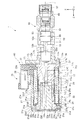
図1は、第1実施形態に係るソレノイド装置の断面図である。本実施形態のソレノイド装置1は、図1に示すように、ソレノイド10と、スプールバルブ50と、を有する。ソレノイド10とスプールバルブ50は、軸方向に沿って配置される。ソレノイド10は、コイル29の励磁により発生する磁力で軸部11を軸方向に移動する。スプールバルブ50は、ソレノイド10の軸方向他方側(フロント側)に位置し、軸部11の移動とともに軸方向に移動可能なスプール弁52を有する。スプール弁52は、バルブボディ51内に移動可能に収容される。以下、構成部材毎に詳細に説明する。なお、コイル29に電流が流れて磁束が発生することを、「コイル29の励磁」とする。
[First Embodiment]
<Overall configuration>
FIG. 1 is a sectional view of the solenoid device according to the first embodiment. As shown in FIG. 1, the
<ソレノイド10>
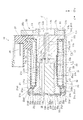
図2は、ソレノイドの断面図である。ソレノイド10は、図1及び図2に示すように、ヨーク21と、コア17と、軸部11と、ボビン25と、コイル29と、プランジャ13、蓋体33、ハウジング30と、を有する。
<
FIG. 2 is a sectional view of the solenoid. As shown in FIGS. 1 and 2, the
(ハウジング30)
ハウジング30は、磁性材料製であり、軸部11、ヨーク21、コア17、ボビン25、コイル29、プランジャ13及び蓋体33を収容する。ハウジング30は、筒状のハウジング本体部31を有する。本実施形態では、ハウジング本体部31は円筒状である。ハウジング本体部31は、第1開口部31aと、第1内壁部31cと、第1カシメ部31dと、を有する。第1開口部31aは、軸方向一方側端部に開口する。第1内壁部31cは、第1開口部31aに隣接してハウジング本体部31の軸方向一方側の内壁31bに、径方向外側で軸方向に円筒状に広がる。第1カシメ部31dは、第1内壁部31cの軸方向一方側端から軸方向一方側へ延びる。第1内壁部31cは、軸方向他方側端に径方向に延びる円環状の第1段部31eを有する。
(Housing 30)
The
本実施形態では、第1内壁部31cの内面と第1カシメ部31dの内面は同一面上にある。また、第1カシメ部31dの径方向の厚さは、ハウジング本体部31の内壁31bの径方向の厚さよりも薄い。第1段部31eは、軸方向一方側へ向いて、軸方向に対して直交する方向に延びる。この第1段部31eに、ヨーク21の第1フランジ部21bの第1の軸方向他方側端面21d1が接触する。
In the present embodiment, the inner surface of the first
第1カシメ部31dの軸方向先端部の径方向内側には、第1開口部31aが開口する。第1開口部31aは、軸方向視において円形状である。この第1開口部31aよりもフロント側に蓋体33が挿入される。蓋体33の周縁部33cは、第1フランジ部21bの第1の軸方向一方側端面21d2に接触する。
A
ハウジング本体部31は、軸方向他方側のハウジング本体部31の内壁31bに径方向外側で軸方向に円筒状に広がる第2内壁部31fを有する。第2内壁部31fは、軸方向一方側端に径方向へ延びる円環状の第2段部31jを有する。第2内壁部31fの内径は、ハウジング本体部31の内壁31bの内径よりも大きい。このため、第2内壁部31fの径方向厚さは、ハウジング本体部31の内壁31bの径方向厚さよりも薄い。
The housing
ハウジング本体部31は、第2内壁部31fのフロント側の端部からフロント側へ延びる第2カシメ部31hを有する。第2カシメ部31hの径方向の厚さは、第2内壁31fの径方向の厚さと同じである。なお、第2カシメ部31hによってスプールバルブ50のバルブボディ51がハウジング30に固定される。
The housing
ハウジング本体部31のフロント側のX軸方向プラス側端部には、ターミナル切欠き部31iが設けられる。コイル29に電気的に接続されたターミナル38を保持するターミナル本体部37は、ターミナル切欠き部31iの径方向内側から外側へ向かって突出する。ターミナル本体部37とコイル29が巻かれたボビン25とは、一体成型品である。
A
(ヨーク21)
ヨーク21は、ハウジング本体部31内のリア側に位置し、軸方向に延びる第1円筒部21aを有する。本実施形態では、第1円筒部21aは、軸方向に貫通する第1貫通孔21hを有する。第1貫通孔21h内にプランジャ13が挿入される。
(Yoke 21)
The
第1円筒部21aの軸方向一方側には、径方向外側に突出する環状の第1フランジ部21bが設けられる。第1フランジ部21bの外径は、ハウジング本体部31の内壁31bの内径よりも大きく、且つ第1内壁部31cの内径よりも僅かに小さい。このため、第1フランジ部21bは、第1内壁部31cに容易に挿入可能である。また、第1フランジ部21bは、第1フランジ部21bの第1の軸方向他方側端面21d1が第1段部31eに接触する。
On one axial side of the first
本実施形態では、第1フランジ部21bは円環状であり、第1フランジ部21bの軸方向厚さは、ハウジング本体部31の内壁31bの肉厚と同程度の厚さ有する。このため、第1フランジ部21bの第1周端部21cは、第1内壁部31cの内面に沿って配置される。よって、ヨーク21を中心軸Jに沿った姿勢で配置することができる。
In the present embodiment, the
第1フランジ部21bは、第1フランジ部21bの第1の軸方向他方側端面21d1が第1段部31eに接触する。また、第1フランジ部21bの第1の軸方向他方側端面21d1とボビン25の軸方向他方側の端面25cは、同一平面上に位置する。
In the
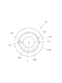
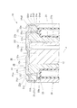
図3は、ヨーク21の平面図である。図4は、ソレノイド10の部分拡大図である。ヨーク21の第1フランジ部21bは、図3及び図4に示すように、少なくとも軸方向一方側が開口して軸方向他方側へ延びる孔部21jを有する。本実施形態では、孔部21jは、第1フランジ部21bを貫通する。孔部21jは、第1フランジ部21bの径方向内側に配置されるとともに、中心軸Jに対して対称な位置に2か所配置される。孔部21jの軸方向他方側に開口する第5開口部21j2は、ボビン25の軸方向一方側の端面25cに接触して塞がれる。
FIG. 3 is a plan view of the
ヨーク21は、ヨーク21の軸方向一方側のヨーク端面21mにおいて、孔部21jの軸方向一方側に開口する第6開口部21j1よりも径方向内側の位置に軸方向一方側へ突出する突起部21kを有する。突起部21kは、突起部21kの軸方向一方側端部が蓋体33の軸方向他方側の内面33fに隙間35を有して位置する。
The
第1円筒部21aの軸方向長さは、図2に示すように、プランジャ13の軸方向長さと同程度の長さを有する。第1円筒部21aの第1貫通孔21hの内径は、プランジャ13の外径よりも僅かに大きい。このため、第1円筒部21aは、プランジャ13を支持するすべり軸受として機能するとともに、プランジャ13の軸方向への移動を可能にする。
The axial length of the first
第1円筒部21aの軸方向他方側(フロント側)の壁部21eの端部は、軸方向他方側へ進むに従って径方向内側へ斜めに傾斜する傾斜面部21fを有する。また、第1円筒部21aの軸方向他方側の壁部21eの径方向外側面には、径方向内側へ窪む第1嵌合部21gが設けられる。この第1嵌合部21gには、後述するカラー41が装着される。
The end portion of the
ヨーク21の第1円筒部21aと第1フランジ部21bとは、一体的になる。即ち、第1円筒部21aと第1フランジ部21bとは、単一部材からなる。このヨーク21は、型成型又は切削加工で得られる。なお、ヨーク21は、第1円筒部21aと第1フランジ部21bとが別体であってもよい。
The first
(プランジャ13)
プランジャ13は、第1円筒部21a内を軸方向に移動する。本実施形態では、プランジャ13は、磁性材料製であり、円柱状である。プランジャ13の外径は、第1円筒部21aの第1貫通孔21hの内径よりも僅かに小さい。
(Plunger 13)
The
プランジャ13は、軸方向に貫通する第2貫通孔13aを有する。本実施形態では、第2貫通孔13aは、フロント側がプランジャ13のフロント側のプランジャ端面13bに開口し、リア側がプランジャ13のリア側のプランジャ端面13cに開口する。第2貫通孔13aは、軸方向視において、軸部11よりも径方向外側に位置する。
The
(コア17)
コア17は、ヨーク21に対して軸方向他方側(フロント側)に位置し、軸方向に延びる第2円筒部17aを有する。第2円筒部17aは、軸方向に延びて軸部11が挿入される第3貫通孔17fを有する。本実施形態では、コア17は、磁性材料製であり、ハウジング30のフロント側に配置されてハウジング30内に固定される。コア17は、カラー41を介してヨーク21に結合されるとともに、ボビン25の内面に接触した状態でハウジング30に固定される。コア17の第2円筒部17aのフロント側には、径方向に突出する環状の第2フランジ部17bが設けられる。第2フランジ部17bの外径は、第2内壁部31fの内径よりも僅かに小さい。
(Core 17)
The
第2フランジ部17bの径方向の第2周端部17cは、第2内壁部31fに接触する。さらに、第2フランジ部17bの第2の軸方向一方側端面17nは、第2段部31jに接触する。このため、コア17は、ハウジング30に対して軸方向一方側(リア側)に位置決めされる。
The radial second
第2円筒部17aのリア側には、リア側が開口してフロント側へ窪む第1空間部17dが設けられる。本実施形態では、第1空間部17dは、中心軸Jに対して同軸上に設けられて、軸方向視において円形状である。第1空間部17dの内径はプランジャ13の外径よりも僅かに大きい。このため、プランジャ13は第1空間部17d内に軸方向に移動可能である。
On the rear side of the second
第1空間部17dには、第1空間部17dのフロント側端部からフロント側へ延びる延長空間部17eが設けられる。延長空間部17eは、リア側が開口してフロント側へ延びる。延長空間部17eの内径は第1空間部17dの内径よりも小さい。延長空間部17eのフロント側の底面には軸部11が通る第3貫通孔17fのリア側の開口部17gが開口する。延長空間部17eは、第1空間部17d内に移動するプランジャ13によって第1空間部17d内の空気を圧縮したときの圧力変化を抑制する。
The
第3貫通孔17fは、リア側が延長空間部17eに連通し、フロント側が第2円筒部17aのフロント側の端面17hに開口する。第3貫通孔17fに軸部11が移動自在に通される。第3貫通孔17fは、軸部11を支持するすべり軸受として機能するとともに、軸部11の軸方向への移動を可能にする。
The third through
ヨーク21の軸方向他方側のヨーク外周面及びコア17の軸方向一方側のコア外周面には、筒状のカラー41が挿入される。ヨーク21及びコア17は、隙間23を有してカラー41を介して結合される。本実施形態では、コア17の第2円筒部17aのリア側には、第2円筒部17aのフロント側よりも小径で円筒状の第2嵌合部17iが設けられる。
A
第2嵌合部17iにはカラー41のフロント側が嵌合される。カラー41のリア側はヨーク21の第1嵌合部21gに嵌合される。このため、ヨーク21とコア17はカラー41を介して結合される。カラー41の肉厚は、ヨーク21の第1円筒部21aの肉厚よりも薄い。本実施形態では、カラー41の径方向の厚さは、ヨーク21の第1円筒部21aの径方向の厚さよりも薄い。このため、磁力線が通る通路を拡大することができる。カラー41は、非磁性材料製である。
The front side of the
第2円筒部17aの第1空間部17dの径方向外側には、リア側へ延びる円筒状の薄肉部17jが設けられ。薄肉部17jは、軸方向一方側へ進むに従って径方向内側に傾く傾斜面部17kを有する。傾斜面部17kを有した薄肉部17jは、コイル29の通電時に、薄肉部17jからプランジャ13側に延びる磁力線を集中させて、プランジャ13をフロント側へ引っ張る力を増大する。
A cylindrical
(軸部11)
軸部11は、図2に示すように、第2円筒部17a内を軸方向に移動する。本実施形態では、軸部11は、非磁性の金属材料製であり、軸部11の外径は第3貫通孔17fの内径よりも僅かに小さい。軸部11のリア側の端部は第1空間部17d内に突出し、軸部11のフロント側の端部はコア17のフロント側の端面17hから突出する。軸部11のリア側には止め輪12が装着される。
(Shaft 11)
As shown in FIG. 2, the
プランジャ13が軸部11をフロント側に移動させる際に、プランジャ13のフロント側のプランジャ端面13bが第1空間部17dの底面に接触する前に止め輪12が延長空間部17eの底面に接触する位置に配置される。このため、軸部11がフロント側へ移動する際に、プランジャ13が第1空間部17dの底面に当接する虞を防止することができる。
When the
(ボビン25)
ボビン25は、円筒状であり、第1円筒部21a及び第2円筒部17aの径方向外側に配置される。本実施形態では、ボビン25は、樹脂製であり、第1円筒部21aの径方向外側の側面21iと、第2円筒部17aの径方向外側の側面17mを覆う。ボビン25は、円筒部25aと、円筒部25aの軸方向両側に設けられて径方向外側へ突出する第3フランジ部25bと、を有する。円筒部25aにコイル29が巻かれる。
(Bobbin 25)
The
X軸方向プラス側の第3フランジ部25bは、径方向外側へ延びてターミナル本体部37に繋がる。コイル29が巻かれたボビン25は、ターミナル本体部37とともに樹脂によって一体成型される。
The
(コイル29)
コイル29は、ボビン25に巻かれる。本実施形態では、コイル29は、ボビン25の円筒部25aの径方向外側の外周面に沿って周方向に巻かれる。コイル29の両端部はターミナル本体部37に設けられたターミナル38に電気的に接続される。
(Coil 29)
The
(蓋体33)
蓋体33は、図2に示すように、非磁性材料製あり、ヨーク21及びプランジャ13に対して軸方向一方側(リア側)に位置する。蓋体33は、円板状であり、蓋体33の外径はハウジング本体部31の内壁31bの内径よりも大きく、且つ第1内壁部31cの内径よりも僅かに小さい。また、蓋体33は、第1カシメ部31dが径方向内側に折れ曲がって蓋体33の周縁部33cに接触している事により、周縁部33cが第1フランジ部21bの第1の軸方向一方側端面21d2に接触した状態でハウジング30に固定される。
(Lid 33)
As shown in FIG. 2, the
本実施形態では、蓋体33は、図2及び図4に示すように、プランジャ13の軸方向一方側のプランジャ端面13cに対向して配置される蓋体本体部33aと、蓋体本体部33aの径方向外側端部から軸方向他方側へ進むに従って径方向外側へ延びる環状の傾斜部33bと、傾斜部33bの径方向外側端部から径方向外側に突出する環状の周縁部33cと、を有する。蓋体33は、ハウジング30に固定された状態で第1開口部31aを塞ぐ。
In this embodiment, as shown in FIG. 2 and FIG. 4, the
蓋体33の周縁部33cは、孔部21jの軸方向一方側に開口する第6開口部21j1よりも径方向外側に延びる第1フランジ部21bの第1の軸方向一方側端面21d2に接触する。このため、周縁部33cによって第6開口部21j1が塞がれることはない。
The
蓋体本体部33aは、蓋体本体部33aの径方向内側にプランジャ13側に突出する突出部33eを有する。突出部33eは、プランジャ13が退避位置Pbに移動した状態でプランジャ13の軸方向一方側のプランジャ端面13cに接触する。突出部33eは、軸方向視において、第2貫通孔13aの軸方向一方側に開口する第4開口部13dと交差しない位置に配置される。本実施形態では、突出部33eは、プランジャ13が退避位置Pbに移動した状態でプランジャ13のリア側のプランジャ端面13cの中央部に接触するとともに、第2貫通孔13aのリア側の第4開口部13dを塞がない大きさを有する。突出部33eは軸方向視において円形状である。
The lid
図4に示すように、蓋体33の軸方向他方側の内面33fと、プランジャ13及びヨーク21との間には、プランジャ13が蓋体33に接触する退避位置Pbに移動した状態で、第2貫通孔13aと孔部21jとを連通する第2空間部36が設けられる。第2空間部36は、プランジャ13が退避位置Pbに移動した状態で、蓋体33の軸方向他方側の内面33fと、ヨークの軸方向一方側のヨーク端面21mと、プランジャ13の軸方向一方側のプランジャ端面13cとで囲まれる領域から、突起部21k及び突出部33eを除いた領域である。また、プランジャ13が退避位置Pbに移動しているときの第2空間部36の容積は、第1空間部17dの容積と、同じ又はより大きい。ヨーク21の突起部21kは、蓋体33の内面33fに対して隙間35を有しているので、この隙間35により第2空間部36の領域を拡大する。
As shown in FIG. 4, between the
<スプールバルブ50>
(バルブボディ51)
バルブボディ51は、図1に示すように、円筒状であり、オイルを流入・流出させる複数のポート55を有する。バルブボディ51は、軸方向に延びてスプール弁52が挿入されたスプール孔部53を有する。スプール孔部53は、バルブボディ51を軸方向に貫通する。スプール孔部53には、複数のポート55が繋がる。バルブボディ51のリア側端部には、径方向に突出するフランジ部54が設けられる。このフランジ部54は、ソレノイド10のハウジング本体部31に設けられ第2カシメ部31hによって加締められてハウジング本体部31に固定される。
<
(Valve body 51)
As shown in FIG. 1, the
(スプール弁52)
スプール弁52は、スプール孔部53の内径よりも僅かに小さい外径を有する複数の大径部52aと、軸方向に隣接する大径部52a同士を繋ぎ大径部52aよりも小径な小径部52bとを有する。スプール弁52は軸方向に移動することで大径部52aがポート55を開閉する。バルブボディ51のフロント側端部には、スプール孔部53のフロント側の開口を塞ぐ閉塞部材57が挿入される。閉塞部材57とスプール弁52のフロント側端部との間には、圧縮ばね60が配置される。このため、スプール弁52は、圧縮ばね60によってリア側へ附勢される。
(Spool valve 52)
The
<ソレノイド10の組み立て方法>
先ず、図1に示すように、ヨーク21を、第1フランジ部21bがリア側に向いた状態でハウジング本体部31のリア側に開口する第1開口部31aからハウジング本体部31内に挿入し、第1フランジ部21bの第1の軸方向他方側端面21d1をハウジング本体部31の第1段部31eに接触させる。
<Assembly method of
First, as shown in FIG. 1, the
ヨーク21の挿入後、蓋体33を、第1開口部31aから突出部33eがフロント側へ向いた姿勢で、ハウジング本体部31内に挿入する。蓋体33は、周縁部33cのフロント側の面33d1がヨーク21の第1フランジ部21bのリア側の第1の軸方向一方側端面21d2に接触する。蓋体33の挿入後、第1カシメ部31dを径方向内側に折り曲げて蓋体33に周縁部33cに接触させて蓋体33をハウジング本体部31に固定する。
After the
蓋体33の固定後、プランジャ13をハウジング本体部31のフロント側に開口する第2開口部31nからハウジング本内部31内に挿入し、プランジャ13をヨーク21の第1円筒部21aの第1貫通孔21hに挿入する。プランジャ13の挿入後、カラー41を、第2開口部31nからハウジング本体部31内に挿入して、ヨーク21の第1嵌合部21gに嵌め合わせる。
After the
カラー41の挿入後、ボビン25とターミナル本体部37が一体成型されたアセンブリ40を、第2開口部31nからハウジング本体部31内に挿入する。ボビン25は、ボビン25の外周面がハウジング本体部31の内壁31bの内面に嵌め合わされて固定される。
After the insertion of the
アセンブリ40の挿入後、軸部11が挿入されたコア17を、第1空間部17dがリア側に向いた状態で、コア17を第2開口部31nからハウジング本体部31内に挿入し、コア17の第2嵌合部17iにヨーク21からフロント側へ延びるカラー41を嵌め合わせる。また、コア17の第2フランジ部17bの第2の軸方向一方側端面17nをハウジング本体部31の第2段部31jに接触させて、ソレノイド10の組み立てが終了する。
After the
なお、ソレノイド10の組み立て方法は、前述した順序に限るものではない。前述した組み立て方法では、プランジャ13をヨーク21内に挿入した後に、アセンブリ40をハウジング本体部31内に挿入したが、アセンブリ40をハウジング本体部31内に挿入した後にプランジャ13をヨーク21内に挿入してもよい。
The method of assembling the
<ソレノイド装置1の作用・効果>
次に、ソレノイド装置1の作用・効果について説明する。図1に示すように、ソレノイド装置1のソレノイド10のコイル29が励磁されると、コイル29に発生する磁力によってプランジャ13がコア17側に吸引される。このため、プランジャ13に接触する軸部11がプランジャ13とともにフロント側に移動する。なお、軸部11の移動時には、圧縮ばね60の付勢に抗して移動する。したがって、軸部11に当接するスプール弁52がフロント側へ移動する。
<Operation and Effect of
Next, the operation and effect of the
一方、ソレノイド10のコイル29が非励磁状態になると、プランジャ13は、コア17からの吸引力が無くなる。このため、圧縮ばね60のフロント側へ向く付勢力によって、スプール弁52はリア側へ移動する。また、スプール弁52のリア側への移動に伴ってソレノイド10の軸部11及びプランジャ13は、リア側へ移動する。
On the other hand, when the
(1)ここで、本実施形態に係る蓋体33の軸方向一方側の内面33fと、プランジャ13及びヨーク21との間には、プランジャ13が蓋体33に接触する退避位置Pbに移動した状態で、第2貫通孔13aと孔部21jとを連通する第2空間部36が設けられる。プランジャ13が軸方向他方側へ移動する場合、第1空間部17d内の空気はプランジャ13に圧縮されて第2貫通孔13aを介して第2空間部36に移動する。一方、プランジャ13が軸方向一方側(退避位置Pb側)へ移動する場合には、第2空間部36及び孔部21j内の空気は、プランジャ13に圧縮されて、第2貫通孔13aを介して第1空間部17d内に移動する。ここで、プランジャ13が退避位置Pb側へ移動する場合、第2空間部36内の空気は、第2貫通孔13aを通って第1空間部17d側へ流れるが、第2空間部36に連通する孔部21jを設けることで、第2空間部36の領域を拡大することができる。このため、プランジャ13が退避位置Pbに移動したときの第2空間部36内の空気圧の上昇する圧力変化を抑えることができ、プランジャ13の移動をスムースにすることができる。
(1) Here, between the
(2)また、プランジャ13が退避位置Pbに移動しているときの第2空間部36の容積は、第1空間部17dの容積に比べて、同一又は大きい。このため、プランジャ13が退避位置Pb側へ向かって移動する場合、第1空間部17dから第2空間部36内に流入する空気は、第1空間部17dの容積と同じ又はより大きい容積を有した第2空間部36内に流入する。このため、プランジャ13が退避位置Pbに移動したときの第2空間部36の空気圧の圧力変化を抑えることができる。
(2) The volume of the
(3)また、孔部21jは第1フランジ部21bを軸方向に貫通する。このため、ソレノイド装置1の限られた空間内に第2空間部36に連通する新たな空間を設けることができる.
(3) The
(4)また、孔部21jの軸方向他方側に開口する第5開口部21j2は、ボビン25の軸方向一方側の端面25cに接触して塞がれる。このため、孔部21jに流入した空気が漏れ出したり、外部の空気がソレノイド装置1内に流入したりする虞を防止することができる。
(4) The fifth opening 21j2 that opens on the other axial side of the
(5)また、蓋体33の周縁部33cは、孔部21jの軸方向一方側に開口する第6開口部21j1よりも径方向外側に延びる第1フランジ部21bの第1の軸方向一方側端面21d2に接触する。このため、蓋体33によって孔部21jの第6開口部21j1が塞がれることはなく、第2空間部36と孔部21jの連通状態を維持できる。
(5) Further, the
(6)また、ヨーク21は、ヨーク21の軸方向一方側のヨーク端面21mにおいて、孔部21jの第6開口部21j1よりも径方向内側の位置に軸方向一方側へ突出する突起部21kを有し、突起部21kは、この軸方方向一方側端部が蓋体33の軸方向他方側の内面33fに接触する。このため、蓋体33が変形する場合、突起部21kが蓋体33の変形を抑制するので、第6開口部21j1の周囲の空間の領域が狭くなる虞を防止することができる。このため、第2空間部36と孔部21jとの連通状態を維持することができる。
(6) In addition, the
(7)また、蓋体本体部33aは、蓋体本体部33aの径方向内側にプランジャ13側に突出する突出部33eを有する。このため、プランジャ13が軸方向一方側に移動する場合、プランジャ13の軸方向一方側のプランジャ端面13cが突出部33eに接触して、プランジャ13の軸方向一方側への移動を規制することができる。
(7) The lid
(8)また、突出部は33e、プランジャが退避位置Pbに移動した状態でプランジャ13の軸方向一方側のプランジャ端面13cに接触する。このため、プランジャ13を退避位置Pbで停止させることができる。
(8) Further, the protruding
(9)また、突出部33eは、軸方向視において、第2貫通孔13aの軸方向一方側に開口する第4開口部13dと交差しない位置に配置される。このため、突出部33eによって第4開口部13dが塞がれる虞を防止することができる。
(9) Further, the
(10)また、第2空間部36は、プランジャ13が退避位置Pbに移動した状態で、蓋体33の内面33fと、ヨーク端面21mと、プランジャ端面13cとで囲まれる領域から、突起部21k及び突出部33eを除いた領域である。このため、突起部21k及び突出部33eがソレノイド装置1に存在する場合でも、第2空間部36を確保することができる。
(10) Further, the
(11)また、蓋体33は、非磁性材料製である。このため、プランジャ13からヨーク21を通ってコイル29に戻る磁力線が蓋体33を通る虞はない。このため、磁気回路の分散を抑制することができる.
(11) The
以上、本発明の好ましい実施形態について説明したが、本発明は、これらの実施形態に限定されず、その要旨の範囲内で種々の変形および変更が可能である。これらの実施形態及びその変形は、発明の範囲及び要旨に含まれると同時に、特許請求の範囲に記載された発名とその均等の範囲に含まれる。 Although the preferred embodiments of the present invention have been described above, the present invention is not limited to these embodiments, and various modifications and changes can be made within the scope of the gist. These embodiments and modifications thereof are included in the scope and spirit of the invention, and are also included in the issuance described in the claims and their equivalents.
例えば、前述した実施形態では、ヨーク21の第1フランジ部21bに設けられた孔部21jは、中心軸Jを中央にして対向する位置に2つ設けられている。この孔部21jを、第1フランジ部21bに周方向に間隔を有して3つ以上設けてもよい。これに伴い、3つ以上設けられた孔部21jの夫々の径方向内側のヨーク端面21mに突起部21kを設けてもよい。
For example, in the above-described embodiment, two
1 ソレノイド装置
11 軸部
13 プランジャ
13a 第2貫通孔
13c プランジャ端面
13d 第4開口部
13e 第3開口部
17 コア
17a 第2円筒部
17d 第1空間部
21 ヨーク
21a 第1円筒部
21b 第1フランジ部
21d1 第1の軸方向他方側端面
21d2 第1の軸方向一方側端面
21j 孔部
21j1 第6開口部
21j2 第5開口部
21k 突起部
21m ヨーク端面
25 ボビン
25c 端面
29 コイル
30 ハウジング
31 ハウジング本体部
31a 第1開口部
31c 第1内壁部
31e 第1段部
33 蓋体
33a 蓋体本体部
33b 傾斜部
33c 周縁部
33d1 面
33e 突出部
33f 内面
Pb 退避位置
REFERENCE SIGNS
Claims (11)
軸方向に延びる第1円筒部を有するヨークと、
前記ヨークに対して軸方向他方側に位置し、軸方向に延びる第2円筒部を有するコアと、
前記第2円筒部内を軸方向に移動する前記軸部と、
前記第1円筒部及び前記第2円筒部の径方向外側に配置されたボビンと、
前記ボビンに巻かれた前記コイルと、
前記第1円筒部内を軸方向に移動するプランジャと、
前記ヨーク及び前記プランジャに対して軸方向一方側に位置する蓋体と、
前記軸部、前記ヨーク、前記コア、前記ボビン、前記コイル、前記プランジャ及び前記蓋体を収容するハウジングと、
を有し、
前記ハウジングは、筒状のハウジング本体部を有し、
前記ハウジング本体部は、
軸方向一方側端部に開口する第1開口部と、
前記第1開口部に隣接して前記ハウジング本体部の軸方向一方側の内壁に、径方向外側で軸方向に円筒状に広がる第1内壁部と、
を有し、
前記第1内壁部は、軸方向他方側端に径方向に延びる円環状の第1段部を有し、
前記ヨークの前記第1円筒部は、前記第1円筒部の軸方向一方側に径方向外側に突出する環状の第1フランジ部を有し、
前記蓋体は、円板状であり、径方向外側に延びる環状の周縁部を有し、
前記第1フランジ部の第1の軸方向他方側端面が前記ハウジング本体部の前記第1段部に接触し、且つ前記蓋体の前記周縁部の軸方向他方側の面が前記第1フランジ部の第1の軸方向一方側端面に接触した状態で、前記ヨーク及び前記蓋体が前記ハウジングに固定され、
前記コアの前記第2円筒部は、軸方向一方側に開口して軸方向他方側へ窪み、移動する前記プランジャを挿脱可能な第1空間部を有し、
前記プランジャは、軸方向に沿って貫通する第2貫通孔を有し、
前記第2貫通孔は、軸方向視において、前記第2貫通孔の軸方向他方側に開口する第3開口部が前記軸部よりも径方向外側に位置し、
前記ヨークの前記第1フランジ部は、少なくとも軸方向一方側が開口して軸方向他方側へ延びる孔部を有し、
前記蓋体の軸方向他方側の内面と、前記プランジャ及び前記ヨークとの間には、前記プランジャが前記蓋体に接触する退避位置に移動した状態で、前記第2貫通孔と前記孔部とを連通する第2空間部が設けられる、
ソレノイド装置。 A solenoid device for moving a shaft portion in an axial direction by a magnetic force generated by exciting a coil,
A yoke having a first cylindrical portion extending in the axial direction;
A core which is located on the other side in the axial direction with respect to the yoke and has a second cylindrical portion extending in the axial direction;
The shaft portion moving in the axial direction in the second cylindrical portion;
A bobbin arranged radially outside the first cylindrical portion and the second cylindrical portion;
The coil wound on the bobbin;
A plunger that moves in the axial direction in the first cylindrical portion;
A lid located on one axial side with respect to the yoke and the plunger;
A housing that houses the shaft portion, the yoke, the core, the bobbin, the coil, the plunger, and the lid;
Has,
The housing has a cylindrical housing body,
The housing body is
A first opening opening at one end in the axial direction;
A first inner wall portion, which is formed on the inner wall on one axial side of the housing main body portion adjacent to the first opening portion and radially outwardly and axially cylindrically expands;
Has,
The first inner wall has an annular first step extending in the radial direction at the other axial end,
The first cylindrical portion of the yoke has an annular first flange portion protruding radially outward on one axial side of the first cylindrical portion,
The lid has a disk shape, and has an annular peripheral portion extending radially outward,
The other end face in the first axial direction of the first flange portion contacts the first step portion of the housing body, and the other axial surface of the peripheral portion of the lid is the first flange portion. The yoke and the lid are fixed to the housing while being in contact with the first axial one-side end surface of the housing,
The second cylindrical portion of the core has a first space portion which is open to one side in the axial direction and is depressed to the other side in the axial direction, and into which the moving plunger can be inserted and removed.
The plunger has a second through hole penetrating along the axial direction,
In the second through-hole, a third opening that opens on the other side in the axial direction of the second through-hole is located radially outside of the shaft when viewed in the axial direction,
The first flange portion of the yoke has a hole that opens at least on one side in the axial direction and extends to the other side in the axial direction,
Between the inner surface on the other side in the axial direction of the lid and the plunger and the yoke, the second through-hole, the hole, and A second space portion communicating the
Solenoid device.
請求項1に記載のソレノイド装置。 2. The solenoid device according to claim 1, wherein a volume of the second space when the plunger is moved to the retracted position is equal to or larger than a volume of the first space. 3.
請求項1に記載のソレノイド装置。 The solenoid device according to claim 1, wherein the hole penetrates the first flange portion in an axial direction.
請求項3に記載のソレノイド装置。 4. The solenoid device according to claim 3, wherein a fifth opening that opens to the other axial side of the hole contacts and closes an end surface of the bobbin on one axial side. 5.
前記プランジャの軸方向一方側のプランジャ端面に対向して配置される蓋体本体部と、
前記蓋体本体部の径方向外側端部から軸方向他方側へ進むに従って径方向外側へ延びる環状の傾斜部と、
前記傾斜部の径方向外側端部から径方向外側に突出する環状の前記周縁部と、
を有し、
前記蓋体の前記周縁部は、前記孔部の軸方向一方側に開口する第6開口部よりも径方向外側に延びる前記第1フランジ部の前記第1の軸方向一方側端面に接触する
請求項1に記載のソレノイド装置。 The lid,
A lid body that is disposed to face the plunger end surface on one axial side of the plunger;
An annular inclined portion extending radially outward as it proceeds from the radially outer end of the lid body to the other axial side,
An annular peripheral portion protruding radially outward from a radially outer end of the inclined portion;
Has,
The peripheral edge portion of the lid contacts the first axial one-side end surface of the first flange portion that extends radially outward from a sixth opening portion that opens on one axial side of the hole. Item 2. The solenoid device according to item 1.
前記突起部は、前記突起部の軸方向一方側端部が前記蓋体の軸方向他方側の前記内面に隙間を有して位置する
請求項5に記載のソレノイド装置。 The yoke has a protruding portion that protrudes toward one axial side at a position radially inward of the sixth opening of the hole on a yoke end surface on one axial side of the yoke,
6. The solenoid device according to claim 5, wherein the protrusion has one end in the axial direction of the protrusion located with a gap on the inner surface on the other axial side of the lid. 7.
請求項6に記載のソレノイド装置。 The solenoid device according to claim 6, wherein the lid main body has a protruding portion that protrudes toward the plunger on a radially inner side of the lid main body.
請求項7に記載のソレノイド装置。 8. The solenoid device according to claim 7, wherein the protrusion contacts the plunger end surface on one side in the axial direction of the plunger in a state where the plunger has moved to the retracted position. 9.
請求項8に記載のソレノイド装置。 9. The solenoid device according to claim 8, wherein the projecting portion is disposed at a position that does not intersect with a fourth opening that opens on one side in the axial direction of the second through hole when viewed in the axial direction. 10.
請求項7から9のいずれか1項に記載のソレノイド装置。 The second space portion includes an inner surface on the other axial side of the lid, the yoke end surface on one axial side of the yoke, and one axial direction of the plunger when the plunger is moved to the retracted position. The solenoid device according to any one of claims 7 to 9, wherein the region is a region excluding the protrusion and the protrusion from a region surrounded by the plunger end surface on the side.
請求項1から10のいずれか1項に記載のソレノイド装置。
The solenoid device according to any one of claims 1 to 10, wherein the lid is made of a non-magnetic material.
Priority Applications (3)
| Application Number | Priority Date | Filing Date | Title |
|---|---|---|---|
| JP2018123010A JP2020004848A (en) | 2018-06-28 | 2018-06-28 | Solenoid device |
| CN201920822249.9U CN210034600U (en) | 2018-06-28 | 2019-06-03 | Solenoid device |
| US16/441,011 US11069467B2 (en) | 2018-06-28 | 2019-06-14 | Solenoid device |
Applications Claiming Priority (1)
| Application Number | Priority Date | Filing Date | Title |
|---|---|---|---|
| JP2018123010A JP2020004848A (en) | 2018-06-28 | 2018-06-28 | Solenoid device |
Publications (1)
| Publication Number | Publication Date |
|---|---|
| JP2020004848A true JP2020004848A (en) | 2020-01-09 |
Family
ID=69007658
Family Applications (1)
| Application Number | Title | Priority Date | Filing Date |
|---|---|---|---|
| JP2018123010A Withdrawn JP2020004848A (en) | 2018-06-28 | 2018-06-28 | Solenoid device |
Country Status (3)
| Country | Link |
|---|---|
| US (1) | US11069467B2 (en) |
| JP (1) | JP2020004848A (en) |
| CN (1) | CN210034600U (en) |
Families Citing this family (5)
| Publication number | Priority date | Publication date | Assignee | Title |
|---|---|---|---|---|
| JP2020004848A (en) * | 2018-06-28 | 2020-01-09 | 日本電産トーソク株式会社 | Solenoid device |
| DE102019113409A1 (en) * | 2019-05-21 | 2020-11-26 | ECO Holding 1 GmbH | Actuator and valve block |
| DE102019121090A1 (en) * | 2019-08-05 | 2021-02-11 | ECO Holding 1 GmbH | Actuator for a hydraulic valve and hydraulic valve |
| US11640864B2 (en) * | 2019-12-05 | 2023-05-02 | Deltrol Corp. | System and method for detecting position of a solenoid plunger |
| JP7446462B2 (en) * | 2020-09-30 | 2024-03-08 | 日立Astemo株式会社 | Solenoid, damping force adjustment mechanism and damping force adjustable shock absorber |
Citations (7)
| Publication number | Priority date | Publication date | Assignee | Title |
|---|---|---|---|---|
| JPS59112079U (en) * | 1983-01-19 | 1984-07-28 | トキコ株式会社 | emergency activation device |
| JPH01246804A (en) * | 1988-03-28 | 1989-10-02 | Matsushita Electric Works Ltd | Electromagnet apparatus |
| JPH01166872U (en) * | 1988-04-28 | 1989-11-22 | ||
| JP2004278644A (en) * | 2003-03-14 | 2004-10-07 | Toyoda Mach Works Ltd | Solenoid valve |
| JP2005351448A (en) * | 2004-06-14 | 2005-12-22 | Nachi Fujikoshi Corp | Solenoid valve |
| JP2008157430A (en) * | 2006-12-26 | 2008-07-10 | Aisin Aw Co Ltd | Solenoid driving device and solenoid valve |
| WO2018072916A1 (en) * | 2016-10-21 | 2018-04-26 | Robert Bosch Gmbh | Electromagnetic actuator |
Family Cites Families (89)
| Publication number | Priority date | Publication date | Assignee | Title |
|---|---|---|---|---|
| US1439692A (en) * | 1920-05-07 | 1922-12-26 | Chicago Pneumatic Tool Co | Overload-circuit breaker |
| US1955201A (en) * | 1932-05-31 | 1934-04-17 | Eclipse Aviat Corp | Circuit controlling device |
| US2199178A (en) * | 1938-04-07 | 1940-04-30 | Wilbur F Hurlburt | Packless laminated solenoid |
| US2468852A (en) * | 1941-06-24 | 1949-05-03 | Westinghouse Electric Corp | Circuit interrupter |
| BE515788A (en) * | 1951-11-27 | |||
| US2931617A (en) * | 1955-05-11 | 1960-04-05 | Minnesota Honeywell Regulator | Damped solenoid valve operator |
| US2907983A (en) * | 1956-06-19 | 1959-10-06 | Leich Electric Co | Mechanical counting relay |
| US3054872A (en) * | 1958-11-28 | 1962-09-18 | Ward Leonard Electric Co | Electrical contactor |
| US3005890A (en) * | 1959-08-20 | 1961-10-24 | Ritepoint Pen And Pencil Compa | Solenoid operated switches |
| NL258418A (en) * | 1959-12-01 | |||
| US3130282A (en) * | 1961-07-14 | 1964-04-21 | Electro Mechanics Inc | Solenoid operated switches |
| US3156797A (en) * | 1961-12-07 | 1964-11-10 | American Mach & Foundry | Plug-in electromagnetic relay |
| BE626352A (en) * | 1961-12-22 | |||
| US3209096A (en) * | 1962-05-24 | 1965-09-28 | Reiner | Plug-in relay construction |
| US3588770A (en) * | 1969-04-19 | 1971-06-28 | Chukyo Gijutsu Center Kk | Open-box type dc solenoid |
| US3633139A (en) * | 1970-04-20 | 1972-01-04 | Lisk Co G W | Solenoid construction |
| JPS4943155A (en) * | 1972-09-02 | 1974-04-23 | ||
| DE2337843C2 (en) * | 1973-07-25 | 1982-10-28 | Robert Bosch Gmbh, 7000 Stuttgart | Solenoid for solenoid operated valves |
| FR2351273A1 (en) * | 1976-05-11 | 1977-12-09 | Paris & Du Rhone | INTERNAL COMBUSTION ENGINE STARTER SWITCH |
| US4166991A (en) * | 1977-10-19 | 1979-09-04 | Acme-Cleveland Development Company | Solenoid |
| JPS5815730Y2 (en) * | 1978-06-14 | 1983-03-30 | 株式会社デンソー | solenoid valve |
| DE2835407C2 (en) * | 1978-08-12 | 1987-01-15 | Robert Bosch Gmbh, 7000 Stuttgart | Electromagnetic switch, especially for starting devices of internal combustion engines |
| JPS55139575A (en) * | 1979-04-13 | 1980-10-31 | Aisin Seiki Co Ltd | Solenoid valve |
| US4442998A (en) * | 1979-07-24 | 1984-04-17 | Aisin Seiki Kabushiki Kaisha | Electromagnetic valve unit |
| US4404533A (en) * | 1981-03-27 | 1983-09-13 | Honda Giken Kogyo Kabushiki Kaisha | Electromagnetic switch device |
| JPH0134326Y2 (en) * | 1981-04-22 | 1989-10-19 | ||
| DE8221714U1 (en) * | 1982-07-30 | 1982-09-23 | Robert Bosch Gmbh, 7000 Stuttgart | Electromagnetic switch, in particular for starting devices for internal combustion engines |
| DE3341625A1 (en) * | 1982-11-25 | 1984-05-30 | Aisin Seiki | SOLENOID UNIT |
| JPS59126608A (en) * | 1983-01-07 | 1984-07-21 | Aisin Seiki Co Ltd | Solenoid apparatus |
| US4797645A (en) * | 1984-03-05 | 1989-01-10 | Mitsubishi Mining & Cement Co., Ltd. | Electromagnetic actuator |
| US4683454A (en) * | 1985-10-31 | 1987-07-28 | Automatic Switch Company | Solenoid actuator with electrical connection modules |
| US4649360A (en) * | 1986-02-28 | 1987-03-10 | Parker Vannifin Corporation | Solenoid valve with contractible assembly ring |
| WO1988002568A1 (en) * | 1986-10-03 | 1988-04-07 | Mitsubishi Denki Kabushiki Kaisha | Starter for engines |
| US4994776A (en) * | 1989-07-12 | 1991-02-19 | Babcock, Inc. | Magnetic latching solenoid |
| US5303012A (en) * | 1993-02-10 | 1994-04-12 | Honeywell Inc. | Single magnet latch valve with position indicator |
| JP3321963B2 (en) * | 1994-02-22 | 2002-09-09 | 株式会社デンソー | Plunger type electromagnetic relay |
| KR100420662B1 (en) * | 1995-09-08 | 2004-06-05 | 도토기키 가부시키가이샤 | Solenoid and Solenoid Valves |
| DE19602118C2 (en) * | 1996-01-22 | 1999-12-30 | Siemens Ag | Electrical switching device |
| FR2752998B1 (en) * | 1996-09-03 | 1998-10-09 | Valeo Equip Electr Moteur | MOTOR VEHICLE STARTER SWITCH WITH AN INTEGRATED AUXILIARY CONTROL RELAY |
| FR2752999B1 (en) * | 1996-09-03 | 1998-10-09 | Valeo Equip Electr Moteur | MOTOR VEHICLE STARTER SWITCH WITH AN INTEGRATED AUXILIARY CONTROL RELAY |
| FR2753302B1 (en) * | 1996-09-06 | 1998-10-16 | Valeo Equip Electr Moteur | STARTER CONTACTOR COMPRISING AN ELECTRONIC CONTROL CIRCUIT INTEGRATED WITH THE CONTACTOR, AND VEHICLE STARTER COMPRISING SUCH A CONTACTOR |
| TW350899B (en) * | 1996-11-29 | 1999-01-21 | Mitsuba Corp | Coaxial engine starter |
| JP2000315448A (en) * | 1999-05-06 | 2000-11-14 | Omron Corp | Electromagnetic relay |
| JP2001143924A (en) * | 1999-11-15 | 2001-05-25 | Aisin Seiki Co Ltd | Electromagnet |
| US6512435B2 (en) * | 2001-04-25 | 2003-01-28 | Charles Willard | Bistable electro-magnetic mechanical actuator |
| JP3870049B2 (en) * | 2001-08-17 | 2007-01-17 | Necトーキン株式会社 | Electromagnetic relay device |
| JP4022857B2 (en) * | 2002-03-15 | 2007-12-19 | 株式会社デンソー | Solenoid valve device |
| JP2004068601A (en) * | 2002-08-01 | 2004-03-04 | Hitachi Ltd | Solenoid and starter using the same |
| JP2005026182A (en) * | 2003-07-02 | 2005-01-27 | Matsushita Electric Works Ltd | Electromagnetic switching device |
| US6720853B1 (en) * | 2003-07-15 | 2004-04-13 | Wabash Magnetics, Llc | Electrically operated solenoid having an adjustable actuator pin length |
| JP4190379B2 (en) * | 2003-09-12 | 2008-12-03 | 富士通コンポーネント株式会社 | Combined electromagnetic relay |
| US7049916B2 (en) * | 2004-01-21 | 2006-05-23 | Keihin Corporation | Electromagnetic apparatus |
| JP4123164B2 (en) * | 2004-02-20 | 2008-07-23 | 株式会社デンソー | Electromagnetic switch for starter |
| JP4306604B2 (en) * | 2004-12-20 | 2009-08-05 | 株式会社デンソー | Magnetic switch for starter |
| EP1829068B1 (en) * | 2004-12-23 | 2018-09-12 | Siemens Aktiengesellschaft | Method and device for the safe operation of a switching device |
| JP4471859B2 (en) * | 2005-01-31 | 2010-06-02 | 富士通コンポーネント株式会社 | Electromagnetic relay |
| JP4525610B2 (en) * | 2006-02-23 | 2010-08-18 | 株式会社デンソー | Electromagnetic switch |
| JP4765761B2 (en) * | 2006-05-12 | 2011-09-07 | オムロン株式会社 | Electromagnetic relay |
| JP2007305468A (en) * | 2006-05-12 | 2007-11-22 | Omron Corp | Electromagnetic relay |
| JP4661721B2 (en) * | 2006-07-26 | 2011-03-30 | 株式会社デンソー | Starter |
| EP2023363B1 (en) * | 2007-08-08 | 2017-08-30 | Denso Corporation | Magnet switch with magnetic core designed to ensure stability in operation thereof |
| US8248195B2 (en) * | 2007-08-10 | 2012-08-21 | Keihin Corporation | Flat electromagnetic actuator |
| JP4525736B2 (en) * | 2007-11-09 | 2010-08-18 | 株式会社デンソー | Linear solenoid |
| JP5125441B2 (en) * | 2007-11-21 | 2013-01-23 | アイシン・エィ・ダブリュ株式会社 | Linear solenoid device and solenoid valve |
| EP2151573B1 (en) * | 2008-08-07 | 2015-04-15 | Denso Corporation | A starting device for combustion engines |
| DE102008059012A1 (en) * | 2008-11-26 | 2010-05-27 | Schaeffler Kg | Electromagnetic actuator for a hydraulic directional control valve and method for its assembly |
| US8118054B2 (en) * | 2008-12-15 | 2012-02-21 | Brooks Instrument, Llc | Solenoid needle valve assembly |
| JP2010278403A (en) * | 2009-06-01 | 2010-12-09 | Denso Corp | Linear actuator |
| JP5418192B2 (en) * | 2009-07-01 | 2014-02-19 | 株式会社デンソー | Electromagnetic relay |
| JP5387296B2 (en) * | 2009-09-30 | 2014-01-15 | 株式会社デンソー | Electromagnetic switch device |
| JP5392002B2 (en) * | 2009-10-28 | 2014-01-22 | 株式会社デンソー | Electromagnetic switch device |
| JP5077331B2 (en) * | 2009-11-16 | 2012-11-21 | 株式会社デンソー | Linear solenoid |
| JP5521852B2 (en) * | 2010-03-30 | 2014-06-18 | アンデン株式会社 | Electromagnetic relay |
| JP5806562B2 (en) * | 2011-01-12 | 2015-11-10 | 富士電機株式会社 | Magnetic contactor |
| US8514037B2 (en) * | 2011-01-14 | 2013-08-20 | GM Global Technology Operations LLC | Dual bipolar magnetic field for rotary high-voltage contactor in automotive lithium-ion battery systems |
| DE202011003471U1 (en) * | 2011-03-03 | 2011-05-05 | Bürkert Werke GmbH | magnetic valve |
| JP5724616B2 (en) * | 2011-05-18 | 2015-05-27 | 株式会社デンソー | Electromagnetic switch |
| JP5862503B2 (en) * | 2012-07-30 | 2016-02-16 | 株式会社デンソー | Linear solenoid |
| JP5971146B2 (en) * | 2013-02-14 | 2016-08-17 | 株式会社デンソー | Linear solenoid |
| JP5962575B2 (en) * | 2013-04-23 | 2016-08-03 | 株式会社デンソー | Starter |
| JP6372995B2 (en) * | 2013-11-11 | 2018-08-15 | 日本電産トーソク株式会社 | solenoid valve |
| JP6328461B2 (en) * | 2014-03-28 | 2018-05-23 | 株式会社Soken | solenoid |
| JP6164167B2 (en) * | 2014-06-25 | 2017-07-19 | 株式会社デンソー | Linear solenoid |
| JP6587527B2 (en) * | 2015-12-03 | 2019-10-09 | 本田技研工業株式会社 | solenoid valve |
| JP6644423B2 (en) | 2016-03-16 | 2020-02-12 | ジヤトコ株式会社 | Solenoid valve |
| US11053903B2 (en) * | 2017-06-27 | 2021-07-06 | Hitachi Automotive Systems, Ltd. | High-pressure fuel supply pump |
| JP2019168090A (en) * | 2018-03-26 | 2019-10-03 | 日本電産トーソク株式会社 | Solenoid valve and flow passage device |
| JP2020004844A (en) * | 2018-06-28 | 2020-01-09 | 日本電産トーソク株式会社 | Solenoid device |
| JP2020004848A (en) * | 2018-06-28 | 2020-01-09 | 日本電産トーソク株式会社 | Solenoid device |
-
2018
- 2018-06-28 JP JP2018123010A patent/JP2020004848A/en not_active Withdrawn
-
2019
- 2019-06-03 CN CN201920822249.9U patent/CN210034600U/en not_active Expired - Fee Related
- 2019-06-14 US US16/441,011 patent/US11069467B2/en not_active Expired - Fee Related
Patent Citations (7)
| Publication number | Priority date | Publication date | Assignee | Title |
|---|---|---|---|---|
| JPS59112079U (en) * | 1983-01-19 | 1984-07-28 | トキコ株式会社 | emergency activation device |
| JPH01246804A (en) * | 1988-03-28 | 1989-10-02 | Matsushita Electric Works Ltd | Electromagnet apparatus |
| JPH01166872U (en) * | 1988-04-28 | 1989-11-22 | ||
| JP2004278644A (en) * | 2003-03-14 | 2004-10-07 | Toyoda Mach Works Ltd | Solenoid valve |
| JP2005351448A (en) * | 2004-06-14 | 2005-12-22 | Nachi Fujikoshi Corp | Solenoid valve |
| JP2008157430A (en) * | 2006-12-26 | 2008-07-10 | Aisin Aw Co Ltd | Solenoid driving device and solenoid valve |
| WO2018072916A1 (en) * | 2016-10-21 | 2018-04-26 | Robert Bosch Gmbh | Electromagnetic actuator |
Also Published As
| Publication number | Publication date |
|---|---|
| CN210034600U (en) | 2020-02-07 |
| US20200005979A1 (en) | 2020-01-02 |
| US11069467B2 (en) | 2021-07-20 |
Similar Documents
| Publication | Publication Date | Title |
|---|---|---|
| CN210034600U (en) | Solenoid device | |
| JP4805320B2 (en) | Solenoid open / close valve | |
| CN206723550U (en) | Electromagnetic valve device | |
| CN210118512U (en) | Solenoid device | |
| WO2018147175A1 (en) | Solenoid valve | |
| US9885424B2 (en) | Electromagnetic valve | |
| JP6317092B2 (en) | solenoid valve | |
| JP7124485B2 (en) | Solenoid device | |
| CN217177611U (en) | Solenoid device | |
| JP6972833B2 (en) | solenoid valve | |
| JP6576674B2 (en) | solenoid valve | |
| CN215293705U (en) | Electromagnetic valve | |
| JP2020053618A (en) | solenoid | |
| JP6999089B2 (en) | solenoid valve | |
| JP2019033215A (en) | Solenoid device and control valve | |
| CN217207977U (en) | Solenoid device | |
| JP6736330B2 (en) | Solenoid valve cartridge assembly, solenoid valve solenoid and solenoid valve | |
| CN215293704U (en) | Electromagnetic valve | |
| CN215293703U (en) | Electromagnetic valve | |
| JP2020041469A (en) | Electromagnetic pump | |
| JP2022181654A (en) | Electromagnetic valve | |
| JP2019019899A (en) | solenoid valve | |
| JP2022181653A (en) | Electromagnetic valve | |
| JP2022181655A (en) | Electromagnetic valve | |
| JP2022126111A (en) | Solenoid device |
Legal Events
| Date | Code | Title | Description |
|---|---|---|---|
| A621 | Written request for application examination |
Free format text: JAPANESE INTERMEDIATE CODE: A621 Effective date: 20210601 |
|
| RD02 | Notification of acceptance of power of attorney |
Free format text: JAPANESE INTERMEDIATE CODE: A7422 Effective date: 20210601 |
|
| RD03 | Notification of appointment of power of attorney |
Free format text: JAPANESE INTERMEDIATE CODE: A7423 Effective date: 20210806 |
|
| RD04 | Notification of resignation of power of attorney |
Free format text: JAPANESE INTERMEDIATE CODE: A7424 Effective date: 20210806 |
|
| A977 | Report on retrieval |
Free format text: JAPANESE INTERMEDIATE CODE: A971007 Effective date: 20220131 |
|
| A131 | Notification of reasons for refusal |
Free format text: JAPANESE INTERMEDIATE CODE: A131 Effective date: 20220201 |
|
| RD04 | Notification of resignation of power of attorney |
Free format text: JAPANESE INTERMEDIATE CODE: A7424 Effective date: 20220401 |
|
| A761 | Written withdrawal of application |
Free format text: JAPANESE INTERMEDIATE CODE: A761 Effective date: 20220722 |