EP1826531A2 - Navigationskreisel - Google Patents
Navigationskreisel Download PDFInfo
- Publication number
- EP1826531A2 EP1826531A2 EP07103112A EP07103112A EP1826531A2 EP 1826531 A2 EP1826531 A2 EP 1826531A2 EP 07103112 A EP07103112 A EP 07103112A EP 07103112 A EP07103112 A EP 07103112A EP 1826531 A2 EP1826531 A2 EP 1826531A2
- Authority
- EP
- European Patent Office
- Prior art keywords
- optical fiber
- light
- laser medium
- electrodes
- hollow passageway
- Prior art date
- Legal status (The legal status is an assumption and is not a legal conclusion. Google has not performed a legal analysis and makes no representation as to the accuracy of the status listed.)
- Granted
Links
Images


Classifications
-
- G—PHYSICS
- G01—MEASURING; TESTING
- G01C—MEASURING DISTANCES, LEVELS OR BEARINGS; SURVEYING; NAVIGATION; GYROSCOPIC INSTRUMENTS; PHOTOGRAMMETRY OR VIDEOGRAMMETRY
- G01C19/00—Gyroscopes; Turn-sensitive devices using vibrating masses; Turn-sensitive devices without moving masses; Measuring angular rate using gyroscopic effects
- G01C19/58—Turn-sensitive devices without moving masses
- G01C19/64—Gyrometers using the Sagnac effect, i.e. rotation-induced shifts between counter-rotating electromagnetic beams
Definitions
- the present invention generally relates to gyroscope systems, and more particularly relates to optical gyroscopes, such as fiber optic gyroscopes and ring laser gyroscopes.
- Ring laser gyroscopes RLGs
- fiber optic gyroscopes FOGs
- RLGs and FOGs work by directing light in opposite directions around a closed optical path enclosing an area whose normal is along an axis of rotation. If the device is rotated about the axis of rotation, the optical path length for the light traveling in one direction will be reduced, while the optical path length for the tight traveling in the opposite direction will be increased. The change in path length causes a phase shift between the two light waves that is proportional to the rate of rotation.
- both RLGs and FOGs have an advantage in that light is directed around the axis of rotation multiple times.
- RLGs a series of mirrors is used to repeatedly reflect the light around the axis forming a high finesse resonator.
- FOGs the light travels around the axis through a coil (with numerous turns) of optical fiber, which often has a length of several kilometers.
- RFOGs resonator fiber optic gyroscopes
- RFOGs resonator fiber optic gyroscopes
- a recirculating element such as a mirror or a fiber coupler
- a multi-turn optical fiber coil to form an optical resonator.
- the combination of the benefits of RLGs and FOGs allows RFOGs to use shorter optical fiber and to be very small.
- One difficulty associated with RFOGs is that phase shifts often occur that are not attributable to rotation, but rather errors due to the fact that monochromatic light is propagating in a glass medium provided by a conventional optical fiber.
- RFOGs typically rely on complicated optical and electronic systems to process and modulate the laser light that is directed into the resonator from an external laser or lasers, as well as process the light signal that comes out of the resonator.
- These electronic systems, including the external laser(s), can increase the overall size and costs of the RFOGs.
- An apparatus for detecting rotation.
- the apparatus comprises an optical fiber having a hollow passageway therethrough, a laser medium within the hollow passageway, and first and second electrodes contacting the laser medium such that when a voltage is applied across the first and second electrodes, the laser medium is excited such that the laser medium emits laser light through the hollow passageway.
- a method for constructing a fiber optic gyroscope comprises providing an optical fiber having an outer surface, first and second opposing ends, a central axis, and a hollow passageway therethrough, the hollow passageway having first and second portions and being symmetric about the central axis, forming first and second holes in the outer surface of the optical fiber to the hollow passageway, the first hole being adjacent to the first portion of the hollow passageway and the second hole being adjacent to the second portion of the hollow passageway, providing a laser medium in the hollow passageway, the laser medium interconnecting the first and second portions of the hollow passageway, and placing respective first and second electrodes into the first and second holes, the first electrode contacting the laser medium at the first portion of the hollow passageway and the second electrode contacting the laser medium at the second portion of the passageway such that when a voltage is applied across the first and second electrodes, the laser medium is excited such that the laser medium emits laser light through the hollow passageway.
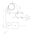
- Figure 1 is a schematic view of a fiber optic gyroscope system according to one embodiment of the present invention including an optical fiber assembly and an optics sub-system;
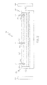
- Figure 2 is a cross-sectional schematic view of the optical fiber assembly illustrated in Figure 1;
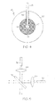
- Figure 3 is a cross-sectional schematic view of a portion of the optical fiber assembly illustrated in Figure 2;
- Figure 4 is a cross-sectional view of the portion of the optical fiber assembly illustrated in Figure 3 taken along line 4-4;
- Figure 5 is a top plan view of a portion of the optical fiber assembly and the optics sub-system illustrated in Figure 1;
- Figure 6 is a schematic view of a fiber optic gyroscope system according to another embodiment of the present invention.
- FIG. 1 to Figure 6 illustrate a gyroscope system.
- the gyroscope system includes an optical fiber with a hollow core that contains a laser medium, such as a gaseous compound or mixture. Holes are formed in the optical fiber, which extend to the hollow core to expose the laser medium within. Electrodes are inserted into the holes to seal the hollow core and contact the laser medium. A power supply is connected to the electrodes to supply a voltage across the electrodes to thereby cause a discharge that excites the laser gain medium and therefore creates laser light within the optical fiber.
- a laser medium such as a gaseous compound or mixture
- FIG. 1 illustrates a gyroscope system 10 according to one embodiment of the present invention.
- the gyroscope system 10 includes an optical fiber assembly 12, an optics sub-system 14, a photodetector 16, a processor/controller 18, and a power supply 20.
- the system 10 may be implemented as either a type of ring laser gyro (RLG), a type of resonator fiber optic gyro (RFOG), or a combination or hybrid of both an RLG and a RFOG, as will be appreciated by one skilled in the art.
- RLG ring laser gyro
- RFOG resonator fiber optic gyro
- the optical fiber assembly 12 includes an optical fiber 22 and three electrodes 24, 26, and 28. As illustrated in Figure 1, the optical fiber 22 has a first end 30 and a second end 32, each being directed toward the optics subsystem 14. As is discussed in greater detail below, a highly reflective mirror 66 in the optical subsystem is positioned to receive the light from fiber end 30 and reflect a large majority of the light emitted from fiber end 30 into fiber end 32, thus forming a resonant cavity for light traveling in the clockwise (CW) direction. Likewise, the mirror 66 is positioned to reflect a large majority of the light exiting fiber end 32 into fiber 30, thus forming a resonant cavity in the counterclockwise (CCW) direction.
- CW clockwise
- CCW counterclockwise
- Lenses 64 may be used to collimate or spatially condition the light to minimize fiber-end to fiber-end optical losses.
- the fiber 22, the mirror 66, and the lenses form an optical ring resonator, which has resonant frequencies in the CW and CCW directions determined by the roundtrip optical pathlength inside the resonator path in each direction, respectively.
- the pathlengths will not be the same, and the resonance frequency of the CW and CCW directions will be different, with the difference proportional to the rotation rate magnitude.
- the laser frequencies in the CW and CCW directions are shifted from each other, proportionally to the rotation rate.
- a central portion of the optical fiber 22 is wound, or arranged, in a coil 34 having an outer diameter 36 of, for example, less than 3 cm with between 20 and 40 turns.
- the outer diameter 36 is approximately 1 cm.
- the coil 34 is formed around an axis of rotation, as is commonly understood.
- Figure 2 schematically illustrates the optical fiber assembly 12 in greater detail with the optical fiber 22 being shown un-wound.
- the optical fiber 22 may have a length 38 of greater than 1 m and be substantially symmetric about a mid-point thereof. In one embodiment, the length 38 of the optical fiber 22 is approximately 1.25 m.
- the optical fiber 22 is, in a preferred embodiment, a glass-based, hollow core, band-gap, optical fiber with an extremely low bend loss.
- the optical fiber 22 includes a region 40 of periodic photonic crystal cells, having a thickness 42 of, for example, between 30 and 40 microns, around a central passageway 44 (i.e., hollow core).
- the central passageway 44 has a radius 46 of, for example, between 2.5 and 10 microns and extends in a direction parallel to, and is symmetric about, a central axis 48 of the optical fiber 22.
- the optical fiber 22 also has an outer glass layer 50 which forms an outer surface 52 of the optical fiber 22.
- the optical fiber 22, in one embodiment, has an overall diameter 54 of between 100 and 125 microns.
- the electrodes 24, 26, and 28 are inserted into holes 56 which lie respectively near the first end 30, a central portion (e.g., the mid-point), and the second end 32 of the optical fiber 22.
- a distance between adjacent electrodes, as measured along the optical fiber 22, may be approximately 0.6125 m (i.e., half the length of the optical fiber 22).
- the holes 56 extend through the glass layer 50 and the periodic photonic crystal cell region 40 to expose the central passageway 44.
- the holes 56 may have widths 58 of, for example, between 5 and 20 microns or larger and may be formed using a carbon dioxide laser, as is commonly understood.
- the electrodes 24, 26, and 28 are pins with widths similar to the widths 58 of the holes to form a seal over the central passageway 44.
- a lower surface 60 of the electrodes 24, 26, and 28 lies a distance away from the central axis 48 of the optical fiber 22 that is greater than the radius 46 of the central passageway 44 so that the electrodes 24, 26, and 28 do not protrude into the central passageway 44.
- the holes 56, and thus the electrodes 24, 26, and 28 extend into the optical fiber 22 in a direction that is substantially perpendicular to the central axis 48.
- a laser (or gain) medium may be formed in, or injected into, the central passageway 44.
- the laser medium may have an index of refraction such that light propagates in nearly free space. Therefore, environmental changes will have virtually no effect on the way light propagates through the gain medium.
- the laser medium may be a low pressure gaseous compound, such as helium neon (HeNe), or a mixture of gases.
- HeNe helium neon
- the electrodes 24, 26, and 28 contact the laser medium at different portions of the central passageway and prevent the laser medium from leaking from the optical fiber 22 through the holes 56.
- end caps 62 may be added to the first end 30 and the second end 32 of the optical fiber 22 to prevent the laser medium from leaking from the ends 30 and 32.
- the end caps 62 may be angled at Brewster's Angle to eliminate losses and reflections, as is commonly understood, or there may be a tapered region in the endcap to prevent Fresnel-reflection losses.
- the optics sub-system 14 includes lenses 64, a recirculator 66, mirrors 68, and a beam splitter 70.
- the lenses 64 are each positioned near a respective end of the optical fiber 22 with a central axis thereof congruent to the central axis 48 of the optical fiber 22 shown in Figures 3 and 4.
- the recirculator 66 is a mirror with a very high reflectivity (e.g., above 95%) and a non-zero transmittance.
- the recirculator 66 may have a reflectivity for a desired state of polarization of light that is significantly higher than the reflectivity for the state of polarization of light that is orthogonal to the desired state of polarization of light.
- the recirculator 66 positioned on a side of both lenses 64 directly opposing the ends 30 and 32 of the optical fiber 22 and oriented at an angle to both ends 30 and 32. This angle may be chosen, in combination with a design of the mirror, to provide high loss for one polarization state, while providing low loss for the other. This enhances the ability for the laser to emit at a single frequency in each direction,
- the optical fiber 22 and the recirculator 66 may jointly form an optical resonator.
- the mirrors 68 are positioned to receive light that is transmitted from the resonator in each direction respectively. Light from the ring laser resonator is transmitted through the recirculator 66 for the purposes of reading out the rotation-signal information.
- the mirrors 68 are positioned to receive light from the resonator output in the two directions respectively direct the two light beams to be recombined, or interfered via beam splitter 70, which in this case, acts as a beam combiner.
- the photodetector 16 is positioned on a side of the beam splitter 70 to receive combined light waves from the beam splitter 70 and the photodetector 16 includes a photodiode, as in commonly understood.
- the processor/controller 18 is in operable communication with the photodetector 16 and the power supply 20 and may include electronic components, including various circuitry and integrated circuits, such as an Application Specific Integration Circuit (ASIC) and/or instructions stored on a computer readable medium to be carried out by a computing system and perform the methods and processes described below.
- ASIC Application Specific Integration Circuit
- the power supply 20 is electrically connected to the electrodes 24, 26, and 28 and although illustrated as a separate component, may be implemented as part of the processor/controller 18. Although not depicted explicitly in Figure 1 the power supply 20 also supplies energy to the photodetector 16, either directly, or via the processor/controller 18.
- the power supply 20 supplies a voltage across electrode 26 and electrodes 24 and 28 so that a plasma discharge current runs from electrode 26 (i.e., anode), through the laser medium within the central passageway 44, and into electrodes 24 and 28 (i.e., cathodes).
- a plasma discharge in the laser gain medium excites atomic and molecular transitions in the gain medium of the laser, and thus stimulates release of photons.
- laser light is generated within the central passageway 44 and propagates in both directions through the optical fiber 22.
- a first portion of the light propagates in the CW direction through the coil 34 towards the first end 30 of the optical fiber 22, and a second portion of the light propagates in the CCW direction through the coil towards the second end 32 of the optical fiber 22.
- the electrodes are arranged to ensure that particle flow due to the plasma discharge from electrode 26 to electrode 28 is equal and opposite to that from electrode 24 to electrode 28, thus reducing or eliminating Fresnel-drag effects, as are well-known in the art.
- Figure 5 illustrates the ends 30 and 32 as the light exits the optical fiber 22.
- the light wave spatially diverges in transitioning from propagation in the fiber to free space, and thus "fans out,” as shown.
- the lens 64 it becomes collimated.
- the collimated light strikes the recirculator 66, and because of the high reflectivity of the recirculator 66, the majority of the light is reflected towards the second end 32 of the optical fiber 22.
- the collimated light passes through the lens 64, it becomes re-focused before entering the second end 32 of the optical fiber 22.
- the second portion of light exits the second end 32 of the optical fiber 22 and is collimated by the first lens 64 through which it passes.
- the majority of the second portion of light is reflected by the recirculator 66 towards the first end 30 and refocused by the second lens 64 through which it passes before entering the first end 30 of the optical fiber 22.
- This process is continually repeated as the light circulating through the optical fiber 22 resonates within the resonator path, which is comprised of path inside the optical fiber 22 and the optical path from fiber end 30 to the recirculator 66 to fiber end 32.
- the photodetector 16 is capable of detecting any relative phase shifts or frequency differences in the two light beams as caused by any rotation of the system 10 about the axis of rotation of the coil 34.
- the photodetector 16 sends an electrical signal to the processor/controller 18 which processes the signal and determines the rate of rotation of the system 10. It is further noted that, while not shown in Figure 1, that errors in rotation rate measurement may arise because of light that is backscattered inside the resonator from one beam into the other, and vice versa.
- One solution that is commonly used in conventional ring laser gyros is to mechanically dither the gyro about its axis of rotation, and to add a degree of randomization of the amplitude of the dither. In this way, errors, sometimes known as lockin, may be greatly reduced or substantially eliminated. This may be similarly employed in embodiments of the present invention.
- One advantage of the gyroscope system described above is that because the light is generated within the optical fiber, the optical and electronic systems external to the resonator may be simplified. Another advantage is that it eliminates rotation rate errors that may stem from signal processing steps that might otherwise be used to derive the rotation signal if the laser light was not generated in resonator, i.e., if it was a passive resonator.
- FIG 6 illustrates a gyroscope system 72 according to another embodiment of the present invention.
- the gyroscope system 72 includes an optical fiber assembly 74, an optics sub-system 76, a photodetector 78, a processor/controller 80, and a power supply 82.
- the system 72 may be in many respects similar to the system 10 shown in Figure 1.
- the optical fiber assembly 74 includes only two electrodes 84 connected to an optical fiber 86. Additionally, the distance between the electrodes 84 (as measured along the optical fiber 86) has been reduced to facilitate in the lasing of the laser medium within the optical fiber 86.
- this distance may be varied, along with the voltage applied across the electrodes 84, depending on the amount (i.e., concentration or density) and type of the laser medium within the optical fiber 86.
- a third electrode could be added at an equal distance to the middle one as in Figure 1, so that the flow induced by the plasma discharge may be counterbalanced, as it is in Figure 1.
- the recirculator 70 and the lenses 64, shown in Figure 1 have been replaced by a concave recirculator 88.
- the concave recirculator 88 may the same high reflectivity as the recirculator 66 shown in Figure 1. However, because of the shape of the concave recirculator 88, light that is reflected by the concave recirculator 88 is re-focused before re-entering the optical fiber 86.
- a further advantage of the embodiment illustrated in Figure 6 is that the light can be recirculated without the use of lens, which further simplifies and reduces the cost of the system 72, and reduces errors that may be caused by environment influences and non-linearities in the glass medium of the lenses.
Landscapes
- Physics & Mathematics (AREA)
- Engineering & Computer Science (AREA)
- Electromagnetism (AREA)
- Power Engineering (AREA)
- General Physics & Mathematics (AREA)
- Radar, Positioning & Navigation (AREA)
- Remote Sensing (AREA)
- Lasers (AREA)
- Gyroscopes (AREA)
Applications Claiming Priority (1)
| Application Number | Priority Date | Filing Date | Title |
|---|---|---|---|
| US11/364,025 US7486401B2 (en) | 2006-02-27 | 2006-02-27 | Laser medium pumping system for a gyroscope |
Publications (3)
| Publication Number | Publication Date |
|---|---|
| EP1826531A2 true EP1826531A2 (de) | 2007-08-29 |
| EP1826531A3 EP1826531A3 (de) | 2009-04-29 |
| EP1826531B1 EP1826531B1 (de) | 2015-01-07 |
Family
ID=38066581
Family Applications (1)
| Application Number | Title | Priority Date | Filing Date |
|---|---|---|---|
| EP07103112.4A Active EP1826531B1 (de) | 2006-02-27 | 2007-02-27 | Navigationskreisel |
Country Status (3)
| Country | Link |
|---|---|
| US (1) | US7486401B2 (de) |
| EP (1) | EP1826531B1 (de) |
| JP (1) | JP5004617B2 (de) |
Cited By (1)
| Publication number | Priority date | Publication date | Assignee | Title |
|---|---|---|---|---|
| CN104981722A (zh) * | 2015-04-23 | 2015-10-14 | 北京航空航天大学 | 一种单分束器透射式光子晶体光纤谐振腔 |
Families Citing this family (9)
| Publication number | Priority date | Publication date | Assignee | Title |
|---|---|---|---|---|
| US7483144B2 (en) * | 2007-03-02 | 2009-01-27 | Honeywell International, Inc. | Apparatus and method for resonant chemical and biological sensing |
| US7697143B2 (en) * | 2008-05-30 | 2010-04-13 | Honeywell International Inc. | Reliable low loss hollow core fiber resonator |
| US7684659B1 (en) | 2008-10-14 | 2010-03-23 | Honeywell International Inc. | Bifilar optical fiber stowage for fiber-optic gyroscope |
| US7889350B2 (en) * | 2008-11-25 | 2011-02-15 | Honeywell International Inc. | RFOG with reduced polarization mode induced bias error |
| US7952772B2 (en) * | 2009-05-08 | 2011-05-31 | Honeywell International Inc. | Photonic crystal fiber sensor |
| US8068233B2 (en) * | 2009-05-14 | 2011-11-29 | Honeywell International Inc. | Compact resonator fiber optic gyroscopes |
| US8274659B2 (en) | 2010-08-30 | 2012-09-25 | Honeywell International Inc. | Resonator fiber optic gyroscopes with reduced rotation rate instability from back reflections |
| US9207082B2 (en) | 2012-08-15 | 2015-12-08 | Honeywell International Inc. | Fiber resonator gyroscope with low round trip loss and high output power |
| TWI461768B (zh) * | 2012-11-01 | 2014-11-21 | Univ Nat Sun Yat Sen | 光纖製作方法及其光纖 |
Family Cites Families (16)
| Publication number | Priority date | Publication date | Assignee | Title |
|---|---|---|---|---|
| US3469922A (en) * | 1967-03-27 | 1969-09-30 | Massachusetts Inst Technology | Gas ring laser gyroscope system |
| US3772611A (en) * | 1971-12-27 | 1973-11-13 | Bell Telephone Labor Inc | Waveguide gas laser devices |
| US4013365A (en) * | 1974-08-29 | 1977-03-22 | The University Of Utah | Laser gyroscope |
| US4396290A (en) * | 1979-09-24 | 1983-08-02 | University Of Utah Research Institute | Two pump-frequency-stimulated Brillouin scattering ring laser gyroscope |
| JPS58190A (ja) * | 1981-06-25 | 1983-01-05 | Toshiba Corp | 導波路型ガスレ−ザ装置 |
| JPS6249683A (ja) * | 1985-08-27 | 1987-03-04 | Mitsubishi Electric Corp | ガスレ−ザ装置 |
| JPH04253035A (ja) * | 1991-01-29 | 1992-09-08 | Fujikura Ltd | 機能性光ファイバの製法 |
| JP3091342B2 (ja) * | 1993-01-14 | 2000-09-25 | ケイディディ株式会社 | ガラス発光素子 |
| US6108358A (en) | 1998-10-13 | 2000-08-22 | Honeywell Inc. | Apparatus for minimizing the effects of laser intensity reduction at cold temperatures in ring laser gyros |
| JP3464401B2 (ja) * | 1999-01-26 | 2003-11-10 | 日本電信電話株式会社 | 光パルス幅圧縮装置 |
| JP4474625B2 (ja) * | 1999-12-14 | 2010-06-09 | 独立行政法人科学技術振興機構 | 超広帯域可変波長多重パルス波形整形装置 |
| US20040061863A1 (en) * | 2002-08-20 | 2004-04-01 | Digonnet Michel J.F. | Fiber optic sensors with reduced noise |
| JP2004101891A (ja) * | 2002-09-10 | 2004-04-02 | Mitsubishi Cable Ind Ltd | 光ファイバの分極方法、および分極された光ファイバを用いたデバイス |
| US6836606B2 (en) * | 2003-01-15 | 2004-12-28 | Fitel U.S.A. Corp. | Filled-core optical fiber and method of making the same |
| JP4242805B2 (ja) * | 2004-05-13 | 2009-03-25 | 三菱電線工業株式会社 | 光ファイバの細孔の充填方法及び光ファイバ |
| US7245381B2 (en) * | 2004-12-20 | 2007-07-17 | Northrop Grumman Corporation | Ring laser gyroscope that does not require mirrors |
-
2006
- 2006-02-27 US US11/364,025 patent/US7486401B2/en active Active
-
2007
- 2007-02-27 JP JP2007047308A patent/JP5004617B2/ja not_active Expired - Fee Related
- 2007-02-27 EP EP07103112.4A patent/EP1826531B1/de active Active
Cited By (4)
| Publication number | Priority date | Publication date | Assignee | Title |
|---|---|---|---|---|
| CN104981722A (zh) * | 2015-04-23 | 2015-10-14 | 北京航空航天大学 | 一种单分束器透射式光子晶体光纤谐振腔 |
| WO2016169023A1 (zh) * | 2015-04-23 | 2016-10-27 | 北京航空航天大学 | 一种单分束器透射式光子晶体光纤谐振腔 |
| CN104981722B (zh) * | 2015-04-23 | 2018-02-02 | 北京航空航天大学 | 一种单分束器透射式光子晶体光纤谐振腔 |
| US9915786B2 (en) | 2015-04-23 | 2018-03-13 | Beihang University | Transmissive photonic crystal fiber ring resonator employing single optical beam-splitter |
Also Published As
| Publication number | Publication date |
|---|---|
| EP1826531A3 (de) | 2009-04-29 |
| JP5004617B2 (ja) | 2012-08-22 |
| JP2007232722A (ja) | 2007-09-13 |
| US7486401B2 (en) | 2009-02-03 |
| US20070201030A1 (en) | 2007-08-30 |
| EP1826531B1 (de) | 2015-01-07 |
Similar Documents
| Publication | Publication Date | Title |
|---|---|---|
| EP1826531B1 (de) | Navigationskreisel | |
| EP1391693B1 (de) | Faseroptische Sensoren mit reduziertem Rauschen | |
| JP5096858B2 (ja) | 光学式共振器ジャイロスコープ、および共振非対称誤差を低減するための方法 | |
| US10852137B2 (en) | Multilayer waveguide optical gyroscope | |
| CN101294810B (zh) | 谐振式空心光子晶体光纤陀螺 | |
| JP5784653B2 (ja) | 伝送モードrfogおよびrfogで回転を検出する方法 | |
| US7751055B2 (en) | Hollow core fiber optical gyro | |
| Feng et al. | Suppression of backreflection noise in a resonator integrated optic gyro by hybrid phase-modulation technology | |
| JP5474282B2 (ja) | 集積光学回転センサおよび回転レートを検出する方法 | |
| EP0616195B1 (de) | Optisches Faserkreisel | |
| EP2128566A2 (de) | Verlässlicher Hohlkern-Faserresonator mit geringem Verlust | |
| Udd | Fiber optic sensors based on the Sagnac interferometer and passive ring resonator | |
| EP1939636A1 (de) | Glasfaserstromsensor und Verfahren zum Erkennen von Strom damit | |
| KR19990008998A (ko) | 진행 방향이 스위칭되는 펄스형 레이저 자이로스코프 | |
| US20100309473A1 (en) | Fiber optic current sensor and method for sensing current using the same | |
| JP3531917B2 (ja) | リングレーザー | |
| Ashley et al. | Applications of SLDs in fiber optical gyroscopes | |
| Ezekiel | Optical gyroscope options: principles and challenges | |
| JP2010230476A (ja) | リングレーザジャイロ | |
| JP2000298024A (ja) | ジャイロ | |
| RU2751052C1 (ru) | Дифференциальный многомодовый волоконный лазерный гироскоп | |
| CN103743392B (zh) | 一种单耦合器双偏振光纤陀螺仪 | |
| Chen et al. | Offset errors caused by the resonance asymmetry in the waveguide-type optical passive resonator gyro | |
| JPH0827194B2 (ja) | 光ファイバージャイロスコープ |
Legal Events
| Date | Code | Title | Description |
|---|---|---|---|
| PUAI | Public reference made under article 153(3) epc to a published international application that has entered the european phase |
Free format text: ORIGINAL CODE: 0009012 |
|
| AK | Designated contracting states |
Kind code of ref document: A2 Designated state(s): AT BE BG CH CY CZ DE DK EE ES FI FR GB GR HU IE IS IT LI LT LU LV MC NL PL PT RO SE SI SK TR |
|
| AX | Request for extension of the european patent |
Extension state: AL BA HR MK YU |
|
| PUAL | Search report despatched |
Free format text: ORIGINAL CODE: 0009013 |
|
| AK | Designated contracting states |
Kind code of ref document: A3 Designated state(s): AT BE BG CH CY CZ DE DK EE ES FI FR GB GR HU IE IS IT LI LT LU LV MC NL PL PT RO SE SI SK TR |
|
| AX | Request for extension of the european patent |
Extension state: AL BA HR MK RS |
|
| RIC1 | Information provided on ipc code assigned before grant |
Ipc: G02B 6/02 20060101ALI20090326BHEP Ipc: H01S 3/03 20060101ALI20090326BHEP Ipc: H01S 3/067 20060101ALI20090326BHEP Ipc: G01C 19/64 20060101AFI20070605BHEP |
|
| 17P | Request for examination filed |
Effective date: 20091016 |
|
| AKX | Designation fees paid |
Designated state(s): DE FR GB IT |
|
| GRAP | Despatch of communication of intention to grant a patent |
Free format text: ORIGINAL CODE: EPIDOSNIGR1 |
|
| INTG | Intention to grant announced |
Effective date: 20140825 |
|
| GRAS | Grant fee paid |
Free format text: ORIGINAL CODE: EPIDOSNIGR3 |
|
| GRAA | (expected) grant |
Free format text: ORIGINAL CODE: 0009210 |
|
| AK | Designated contracting states |
Kind code of ref document: B1 Designated state(s): DE FR GB IT |
|
| REG | Reference to a national code |
Ref country code: GB Ref legal event code: FG4D |
|
| REG | Reference to a national code |
Ref country code: DE Ref legal event code: R096 Ref document number: 602007039932 Country of ref document: DE Effective date: 20150226 |
|
| REG | Reference to a national code |
Ref country code: DE Ref legal event code: R097 Ref document number: 602007039932 Country of ref document: DE |
|
| PLBE | No opposition filed within time limit |
Free format text: ORIGINAL CODE: 0009261 |
|
| STAA | Information on the status of an ep patent application or granted ep patent |
Free format text: STATUS: NO OPPOSITION FILED WITHIN TIME LIMIT |
|
| 26N | No opposition filed |
Effective date: 20151008 |
|
| REG | Reference to a national code |
Ref country code: FR Ref legal event code: PLFP Year of fee payment: 10 |
|
| REG | Reference to a national code |
Ref country code: FR Ref legal event code: PLFP Year of fee payment: 11 |
|
| PGFP | Annual fee paid to national office [announced via postgrant information from national office to epo] |
Ref country code: DE Payment date: 20170227 Year of fee payment: 11 |
|
| PGFP | Annual fee paid to national office [announced via postgrant information from national office to epo] |
Ref country code: GB Payment date: 20170126 Year of fee payment: 11 |
|
| PGFP | Annual fee paid to national office [announced via postgrant information from national office to epo] |
Ref country code: IT Payment date: 20170214 Year of fee payment: 11 |
|
| REG | Reference to a national code |
Ref country code: FR Ref legal event code: PLFP Year of fee payment: 12 |
|
| REG | Reference to a national code |
Ref country code: DE Ref legal event code: R119 Ref document number: 602007039932 Country of ref document: DE |
|
| GBPC | Gb: european patent ceased through non-payment of renewal fee |
Effective date: 20180227 |
|
| PG25 | Lapsed in a contracting state [announced via postgrant information from national office to epo] |
Ref country code: DE Free format text: LAPSE BECAUSE OF NON-PAYMENT OF DUE FEES Effective date: 20180901 |
|
| PG25 | Lapsed in a contracting state [announced via postgrant information from national office to epo] |
Ref country code: IT Free format text: LAPSE BECAUSE OF NON-PAYMENT OF DUE FEES Effective date: 20180227 Ref country code: GB Free format text: LAPSE BECAUSE OF NON-PAYMENT OF DUE FEES Effective date: 20180227 |
|
| P01 | Opt-out of the competence of the unified patent court (upc) registered |
Effective date: 20230525 |
|
| PGFP | Annual fee paid to national office [announced via postgrant information from national office to epo] |
Ref country code: FR Payment date: 20250224 Year of fee payment: 19 |