US3772611A - Waveguide gas laser devices - Google Patents
Waveguide gas laser devices Download PDFInfo
- Publication number
- US3772611A US3772611A US00212605A US3772611DA US3772611A US 3772611 A US3772611 A US 3772611A US 00212605 A US00212605 A US 00212605A US 3772611D A US3772611D A US 3772611DA US 3772611 A US3772611 A US 3772611A
- Authority
- US
- United States
- Prior art keywords
- tube
- bore
- discharge
- waveguide
- resonator
- Prior art date
- Legal status (The legal status is an assumption and is not a legal conclusion. Google has not performed a legal analysis and makes no representation as to the accuracy of the status listed.)
- Expired - Lifetime
Links
- 230000000737 periodic effect Effects 0.000 claims abstract description 11
- 230000005855 radiation Effects 0.000 claims description 12
- 230000007704 transition Effects 0.000 claims description 10
- 239000000463 material Substances 0.000 claims description 6
- 230000000149 penetrating effect Effects 0.000 claims description 2
- 230000010355 oscillation Effects 0.000 abstract description 6
- 239000010409 thin film Substances 0.000 abstract description 5
- 230000005284 excitation Effects 0.000 abstract description 4
- 239000005357 flat glass Substances 0.000 abstract description 4
- 230000002452 interceptive effect Effects 0.000 abstract description 3
- 238000000034 method Methods 0.000 abstract description 2
- 239000007789 gas Substances 0.000 description 22
- 230000004048 modification Effects 0.000 description 4
- 238000012986 modification Methods 0.000 description 4
- 230000003287 optical effect Effects 0.000 description 3
- VYPSYNLAJGMNEJ-UHFFFAOYSA-N Silicium dioxide Chemical compound O=[Si]=O VYPSYNLAJGMNEJ-UHFFFAOYSA-N 0.000 description 2
- CPBQJMYROZQQJC-UHFFFAOYSA-N helium neon Chemical compound [He].[Ne] CPBQJMYROZQQJC-UHFFFAOYSA-N 0.000 description 2
- AFAUWLCCQOEICZ-UHFFFAOYSA-N helium xenon Chemical compound [He].[Xe] AFAUWLCCQOEICZ-UHFFFAOYSA-N 0.000 description 2
- 239000000203 mixture Substances 0.000 description 2
- 238000005086 pumping Methods 0.000 description 2
- 230000002269 spontaneous effect Effects 0.000 description 2
- 238000004458 analytical method Methods 0.000 description 1
- 238000006243 chemical reaction Methods 0.000 description 1
- 238000010276 construction Methods 0.000 description 1
- 230000008878 coupling Effects 0.000 description 1
- 230000001808 coupling effect Effects 0.000 description 1
- 238000010168 coupling process Methods 0.000 description 1
- 238000005859 coupling reaction Methods 0.000 description 1
- 238000010894 electron beam technology Methods 0.000 description 1
- 230000007717 exclusion Effects 0.000 description 1
- 239000010408 film Substances 0.000 description 1
- 239000011521 glass Substances 0.000 description 1
- 239000002184 metal Substances 0.000 description 1
- 238000002310 reflectometry Methods 0.000 description 1
- 235000012239 silicon dioxide Nutrition 0.000 description 1
- 239000000377 silicon dioxide Substances 0.000 description 1
- 238000004611 spectroscopical analysis Methods 0.000 description 1
Images

Classifications
-
- H—ELECTRICITY
- H01—ELECTRIC ELEMENTS
- H01S—DEVICES USING THE PROCESS OF LIGHT AMPLIFICATION BY STIMULATED EMISSION OF RADIATION [LASER] TO AMPLIFY OR GENERATE LIGHT; DEVICES USING STIMULATED EMISSION OF ELECTROMAGNETIC RADIATION IN WAVE RANGES OTHER THAN OPTICAL
- H01S3/00—Lasers, i.e. devices using stimulated emission of electromagnetic radiation in the infrared, visible or ultraviolet wave range
- H01S3/09—Processes or apparatus for excitation, e.g. pumping
- H01S3/097—Processes or apparatus for excitation, e.g. pumping by gas discharge of a gas laser
- H01S3/0975—Processes or apparatus for excitation, e.g. pumping by gas discharge of a gas laser using inductive or capacitive excitation
-
- H—ELECTRICITY
- H01—ELECTRIC ELEMENTS
- H01S—DEVICES USING THE PROCESS OF LIGHT AMPLIFICATION BY STIMULATED EMISSION OF RADIATION [LASER] TO AMPLIFY OR GENERATE LIGHT; DEVICES USING STIMULATED EMISSION OF ELECTROMAGNETIC RADIATION IN WAVE RANGES OTHER THAN OPTICAL
- H01S3/00—Lasers, i.e. devices using stimulated emission of electromagnetic radiation in the infrared, visible or ultraviolet wave range
- H01S3/02—Constructional details
- H01S3/03—Constructional details of gas laser discharge tubes
- H01S3/0315—Waveguide lasers
-
- H—ELECTRICITY
- H01—ELECTRIC ELEMENTS
- H01S—DEVICES USING THE PROCESS OF LIGHT AMPLIFICATION BY STIMULATED EMISSION OF RADIATION [LASER] TO AMPLIFY OR GENERATE LIGHT; DEVICES USING STIMULATED EMISSION OF ELECTROMAGNETIC RADIATION IN WAVE RANGES OTHER THAN OPTICAL
- H01S3/00—Lasers, i.e. devices using stimulated emission of electromagnetic radiation in the infrared, visible or ultraviolet wave range
- H01S3/05—Construction or shape of optical resonators; Accommodation of active medium therein; Shape of active medium
- H01S3/06—Construction or shape of active medium
- H01S3/063—Waveguide lasers, i.e. whereby the dimensions of the waveguide are of the order of the light wavelength
- H01S3/0632—Thin film lasers in which light propagates in the plane of the thin film
- H01S3/0635—Thin film lasers in which light propagates in the plane of the thin film provided with a periodic structure, e.g. using distributed feed-back, grating couplers
-
- H—ELECTRICITY
- H01—ELECTRIC ELEMENTS
- H01S—DEVICES USING THE PROCESS OF LIGHT AMPLIFICATION BY STIMULATED EMISSION OF RADIATION [LASER] TO AMPLIFY OR GENERATE LIGHT; DEVICES USING STIMULATED EMISSION OF ELECTROMAGNETIC RADIATION IN WAVE RANGES OTHER THAN OPTICAL
- H01S3/00—Lasers, i.e. devices using stimulated emission of electromagnetic radiation in the infrared, visible or ultraviolet wave range
- H01S3/05—Construction or shape of optical resonators; Accommodation of active medium therein; Shape of active medium
- H01S3/08—Construction or shape of optical resonators or components thereof
- H01S3/081—Construction or shape of optical resonators or components thereof comprising three or more reflectors
- H01S3/083—Ring lasers
Definitions
- ABSTRACT There are disclosed gas lasers in which the light is guided by a hollow dielectric waveguide which also serves to confine the discharge. These lasers are typically designed to have resonators with Fresnel numbers small enough (less than -05) to suppress the dominant free space mode and having sufficient gain for a waveguide mode of oscillation to exist. Each laser has an internal resonator structure and is designed in such a way that the electrical excitation of the gas discharge can be accomplished without interfering with the light guiding properties of the waveguide. Several novel techniques fonigrgijng waveguide laser tubes of the required small dimensions are "5156 disclosed.
- the embodiments include a capillary ringtype configuration that is r.f.-excited, a distributed feedback configuration using periodic changes in waveguide bore cross section, or wall index of refraction, and various rectangular waveguide configurations, for example, two flat glass plates spaced at the edges by two thin-film strips.
- This invention relates to gas lasers in which the light is guided by a hollow dielectric waveguide which also serves to confine the discharge. Such lasers are designed so that a waveguide mode oscillates to the exclusion of free space modes.
- improved waveguide gas lasers employ various internal-mirror configurations that advantageously provide a minimum of interference between the optical resonator and the electrical discharge pumping means. It is found that extremely small laser lengths, perhaps as small as a fraction of a centimeter, may now be practical.
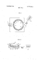
- waveguide gas laser 0scillation is achieved in the mirrorless configuration including the ring-type capillary tube 11 having a smooth wall 13. on its inner bore and an active gas 12 filling that bore.
- the tube 11 by closing on itself, forms a ring resonator. It is pumped purely by the r'.f.-excitation from the source 14 supplied through the coil 15, or electrodes spaced along the tube in conventional manner.
- An output beam for use in the utilization apparatus 18 is illustratively extracted from the ring-type laser by a prism 16 separated by a small gap from the flat portion 17 of the tube wall. This prism couples the waveguide mode to a free space beam via the evanescent fields extending into the prism.
- a high-gain laser transition such as the 3.5 micrometer helium xenon laser line.
- a relatively high-gain transition seems desirable for rings of diameters between about IO centimeters and a meter because the radiation losses through the evanscent field of the waveguided laser radiation with such continuous curvature are appreciable.
- the absence of mirrors may make such a ring laser useful for rotation rate sensing, as the mirror scattering coupling effects (which limit the performance of conventional ring laser rotation rate sensors) are avoided.
- DC-excitation is desirable for waveguide gas lasers which are to have a shorter pathlength or which are to use somewhat lower-gain media. It should be noted that waveguide gas lasers with shorter pathlengths may be of interest in integrated optical circuits of various proposed types.
- the mirrors are illustratively spaced a small distance from the waveguide to allow a dc discharge path.
- the embodiment of FIG. 2 specifically includes the capillary tube 21 which, illustratively, may have an internal diameter of about 0.017 of an inch and a length of 5 centimeters.
- the gaps between the ends of capillary tube 21 and the reflective surfaces 28 and 29 supported by outer containers 30 and 31 should be of the order of, or less than the bore of, the waveguide in order to avoid appreciable diffraction loss.
- the outer containers 30 and 31 make contact with tube 21 relatively near to its center and enclose not only the major portion of the gas volume, but also the anode 25 and the cathode 26 near respective ends of tube 21.
- the dcexcitation source 24 is illustrativey connected in appropriate polarity between anode 25 and cathode 29 in order to supply a discharge through the gas.
- the reflective surface 29 is made partially transparent to extract an output beam for use in utilization apparatus 27.
- the Fresnel number of the laser of FIG. 2 is typically less than about 0.5; and, for the case in which only dcexcitation is used, as shown, the resonator length is short enough to avoid plasma instability in the active gas, here illustratively a helium-neon mixture.
- FIG. 3 may be provided. This arrangement is very similar to that of FIG. 2 except that the reflective surfaces are protected in that cuts transverse to the tube axis are made through one-half of the tube wall; for example, the cuts 34 and 35 spaced from reflective surfaces 28 and 29, respectively. The discharge between electrodes 25 and 26 passes through these cuts.
- the Fresnel number of the waveguide section is preferably of the order of about 0.5 or less.
- the capillary tube 31 illustratively has an internal diameter of about 0.017 of an inch and the cuts 34 and 35 are about 0.014 of an inch along the tube axis. I have measured the loss of such a cut in a 0.017 inch-bore waveguide under passive conditions to be only about 0.5 percent, with no observable mode conversion.
- FIG. 4 A further modification of the embodiment of FIG. 2 is shown in FIG. 4.
- This modification employs the reflectors 45 and 46 as the electrodes for the discharge and eliminates the need for the gaps. Therefore, the dcexcitation source 44 is connected between electrodes 45 and 46.
- the laser has a bore length and inner lateral dimension similar to those of FIG. 3. Gas mixtures such as helium-xenon or helium-neon, could be used, since metal is a good reflector at 3.5 micrometers, 3.39 micrometers, or other wavelengths in the infrared.
- the embodiment of FIG. 4 also assumes a rectangular cross section of the bore of the capillary tube 41.
- the tube 41 could consist of upper and lower flat plates spaced at the back and front edges by thin films 61 and 62, respectively, each of which extends the length of the tube and together define the lateral extent of the bore.
- the cross sections of the tube 41 in FIG. 4 are shown at three different depths in the tube to show its structure farthest from the viewer at the left, along its axis at the center, and nearest to the viewer at the right.
- This type of construction appears feasible since it is now within the stage of the art to make very flat surfaces on such glass plates and to deposit the dielectric thin films 61 and 62, illustratively of silicon dioxide, with very carefully controlled thicknesses and smooth edges.
- FIG. 1 is not the only possible embodiment which eliminates the need for the lumped type of reflectors used in the other above-mentioned embodiments.
- discrete or lumped reflectors are eliminated by smooth periodic variations in the inner surface contours of the capillary 51, thereby changing the bore diameter in a periodic fashion or by periodic index-of-refraction variations in the inner wall of the tube, as illustratively shown by the markings 54 and 55 in the embodiments of FIG. 5.
- anode and the cathode 26 of the pumping arrangement can be disposed in the enlarged end containers 56 and 58 communicating with the bore of tube 51 without interfering with the action of the optical resonator.
- Such an excitation arrangement insures that the entire length of the gaseous active medium, in line with the bore of tube 51, is excited so that it will have a population inversion and thereby maximize gain.
- Output coupling can be provided by reducing the total reflectivity of one of the sets of index variations, for example, the set 55, so that an output beam may be coupled through the end wall 59 of the laser through Still other modifications of the disclosed embodiments are possible.
- rectangular cross section waveguides for such lasers could be made by sputterin'g a chan riel in a dielectric plate by a scanned electron beam or by using four polished flat glass strips to construct the embodiment of FIG. 4 instead of deposit- LII ing the thin films 6 1 and,62 of the embodiment of FIG. 4 duiing thefabiication of the capillary.
- a gas laser comprising a capillary tube of bore diameter a suitable for waveguiding at wavelength A, said tube consisting essentially of material of uniform index to provide guiding primarily within said bore, a gaseous active medium disposed at least partially within the bore of said capillary tube and having a transition capable of providing stimulated emission of radiation at wavelength A, means for establishing a discharge through sai medium to invert the populations of the energy levels of said transition, and a resonator of length b for which the Fresnel number alb h is less than about 0.5, said resonator together with the tube and said discharge establishing means comprising an enclosure for said medium, the capillary tube having open ends, and the resonator and the discharge establishing means including a pair of reflective metallic members closing the ends of said tube, one of said members being partially transparent for the radiation of wavelength A, and
- a gas laser comprising a capillary tube of bore diameter a suitable for waveguiding a wavelength A, said tube consisting essentially of material of uniform index to provide guiding primarily within said bore,
- a gaseous active medium disposed at least partially within the bore of said capillary tube and having a transition capable of providing stimulated emission of radiation at wavelength A
- the capillary tube comprising at least two flat dielectric plates and means including two dielectric films between said plates and in contact therewith for forming a rectangular tube bore between said plates.
- a gas laser comprising a capillary tube of bore diameter a suitable for waveguiding at wavelength K, said tube consisting essentially of material of uniform index to provide guiding primarily within said bore,
- a gaseous active medium disposed at least partially within the bore of said capillary tube and having a transition capable of providing stimulated emission of radiation at wavelength A, means for establishing a discharge through said medium to invert the populations of the energy levels of said transistion, and a resonator of length b for which the Fresnel number alb lt is less than about 0.5, said resonator together with the tube and said discharge establishing means comprising an enclosure for said medium, the capillary tube having open ends, and the resonator comprising periodic variations in the guiding properties of said tube, said variations being distributed axially along said tube adjacent the bore throughout portions near said ends at a multiple of M4, the discharge establishing means comprising dielectric members forming bulbous enclosures over said ends of said tube, and a cathode and an anode penetrating respective ones of said dielectric members.
Landscapes
- Physics & Mathematics (AREA)
- Electromagnetism (AREA)
- Engineering & Computer Science (AREA)
- Plasma & Fusion (AREA)
- Optics & Photonics (AREA)
- Lasers (AREA)
Abstract
There are disclosed gas lasers in which the light is guided by a hollow dielectric waveguide which also serves to confine the discharge. These lasers are typically designed to have resonators with Fresnel numbers small enough (less than *0.5) to suppress the dominant free space mode and having sufficient gain for a waveguide mode of oscillation to exist. Each laser has an internal resonator structure and is designed in such a way that the electrical excitation of the gas discharge can be accomplished without interfering with the light guiding properties of the waveguide. Several novel techniques for forming waveguide laser tubes of the required small dimensions are also disclosed. The embodiments include a capillary ring-type configuration that is r.f.-excited, a distributed feedback configuration using periodic changes in waveguide bore cross section, or wall index of refraction, and various rectangular waveguide configurations, for example, two flat glass plates spaced at the edges by two thin-film strips.
Description
m air/721ml 1 Nov. 13, 1973 WAVEGUIDE GAS LASER DEVICES [75] Inventor: Peter William Smith, Colts Neck,
[73] Assignee: Bell Telephone Laboratories,
7 Incorporated, Murray Hill, NJ.
22 Filed: Dec. 27, 1971 211 App]. No.: 212,605
OTHER PUBLICATIONS Basov et ai., Optics & Spectroscopy 15, (3), September 1963, pp, 235-236.
Primary Examiner-David Schonberg Assistant ExaminerR. J. Webster Att0rneyW. L. Keefauver [57] ABSTRACT There are disclosed gas lasers in which the light is guided by a hollow dielectric waveguide which also serves to confine the discharge. These lasers are typically designed to have resonators with Fresnel numbers small enough (less than -05) to suppress the dominant free space mode and having sufficient gain for a waveguide mode of oscillation to exist. Each laser has an internal resonator structure and is designed in such a way that the electrical excitation of the gas discharge can be accomplished without interfering with the light guiding properties of the waveguide. Several novel techniques fonigrgijng waveguide laser tubes of the required small dimensions are "5156 disclosed. The embodiments include a capillary ringtype configuration that is r.f.-excited, a distributed feedback configuration using periodic changes in waveguide bore cross section, or wall index of refraction, and various rectangular waveguide configurations, for example, two flat glass plates spaced at the edges by two thin-film strips.
3 Claims, 5 Drawing Figures UTlLlZATiON SMOOTH PERIODIC 'SURFACE CONTOUR OR INDEX VARIATIONS E-fies calm 331194.50
SHEET 10F 2 PATENTED NOV 13 I975 FIG.
EXCITATION SOURCE FIG. 2
PAIENTEDIIIII I 3 I975 SHEET 2 or 2 FIG. 3
, UTILIZATION APPARATUS FIG. 4
UTILIZATION APPARATUS IIE UTILIZATION APPARATUS T 59 55;; I 58 SMOOTH PERIODIC SURFACE CONTOUR OR INDEX VARIATIONS WAVEGUIDE GAS LASER DEVICES BACKGROUND OF THE INVENTION This invention relates to gas lasers in which the light is guided by a hollow dielectric waveguide which also serves to confine the discharge. Such lasers are designed so that a waveguide mode oscillates to the exclusion of free space modes.
In US. Pat. No. 3,386,043, issued May 28,1968, it is shown that a waveguide mode of oscillation can exist in a dielectric capillary tube, even though the central core filled with gas has a lower index of refraction than its surroundings. For this mode of oscillation to be established, the dominant free space mode must be cut off. Most broadly, the bore diameter a should be less than 1) times )t, where b is the single pass length of the resonator and k is the wavelength of the intended oscillation. Since the ratio a/b k is known as the Fresnel number, it is seen that a low Fresnel number is required for this type of gas laser.
Nevertheless, it has been found that several other conditions are desirable for the operation of waveguide gas lasers. Forexample, in my article in Applied Physics Letters, Vol. 19, page I32 (1971), I show that the use of a combination of r.f.- and dc-excitations is desirable for achieving oscillation threshold without characteristic plasma instabilities.
Although high gains per unit length have been obtained with waveguide gas lasers employing Brewsterangle windows, configurations providing improved gain, efficiency, compactness and utility are desirable.
SUMMARY OF THE INVENTION According to my invention, improved waveguide gas lasers employ various internal-mirror configurations that advantageously provide a minimum of interference between the optical resonator and the electrical discharge pumping means. It is found that extremely small laser lengths, perhaps as small as a fraction of a centimeter, may now be practical.
As a further feature of my invention, I have determined that such lasers can be made entirely without conventional reflectors of the type used in gas lasers and that, instead, the resonator may be formed by means of a continuous ring-like path or by a distributed-feedback type of reflector.
BRIEF DESCRIPTION OF THE DRAWING DESCRIPTION OF ILLUSTRATIVE EMBODIMENTS In the embodiment of FIG. 1, waveguide gas laser 0scillation is achieved in the mirrorless configuration including the ring-type capillary tube 11 having a smooth wall 13. on its inner bore and an active gas 12 filling that bore. The tube 11, by closing on itself, forms a ring resonator. It is pumped purely by the r'.f.-excitation from the source 14 supplied through the coil 15, or electrodes spaced along the tube in conventional manner. An output beam for use in the utilization apparatus 18 is illustratively extracted from the ring-type laser by a prism 16 separated by a small gap from the flat portion 17 of the tube wall. This prism couples the waveguide mode to a free space beam via the evanescent fields extending into the prism.
For best operation of an embodiment like that of FIG. 1, I suggest the use of a high-gain laser transition such as the 3.5 micrometer helium xenon laser line. A relatively high-gain transition seems desirable for rings of diameters between about IO centimeters and a meter because the radiation losses through the evanscent field of the waveguided laser radiation with such continuous curvature are appreciable. Nevertheless, the absence of mirrors may make such a ring laser useful for rotation rate sensing, as the mirror scattering coupling effects (which limit the performance of conventional ring laser rotation rate sensors) are avoided.
DC-excitation is desirable for waveguide gas lasers which are to have a shorter pathlength or which are to use somewhat lower-gain media. It should be noted that waveguide gas lasers with shorter pathlengths may be of interest in integrated optical circuits of various proposed types.
In order to use dc-excitation in the embodiment of FIG. 2, the mirrors are illustratively spaced a small distance from the waveguide to allow a dc discharge path. The embodiment of FIG. 2 specifically includes the capillary tube 21 which, illustratively, may have an internal diameter of about 0.017 of an inch and a length of 5 centimeters. The gaps between the ends of capillary tube 21 and the reflective surfaces 28 and 29 supported by outer containers 30 and 31 should be of the order of, or less than the bore of, the waveguide in order to avoid appreciable diffraction loss. The outer containers 30 and 31 make contact with tube 21 relatively near to its center and enclose not only the major portion of the gas volume, but also the anode 25 and the cathode 26 near respective ends of tube 21. The dcexcitation source 24 is illustrativey connected in appropriate polarity between anode 25 and cathode 29 in order to supply a discharge through the gas. The reflective surface 29 is made partially transparent to extract an output beam for use in utilization apparatus 27. The Fresnel number of the laser of FIG. 2 is typically less than about 0.5; and, for the case in which only dcexcitation is used, as shown, the resonator length is short enough to avoid plasma instability in the active gas, here illustratively a helium-neon mixture.
Because an overly strong discharge in the embodiment of FIG. 2 may damage the reflective surfaces 28 and 29, the alternative arrangement of FIG. 3 may be provided. This arrangement is very similar to that of FIG. 2 except that the reflective surfaces are protected in that cuts transverse to the tube axis are made through one-half of the tube wall; for example, the cuts 34 and 35 spaced from reflective surfaces 28 and 29, respectively. The discharge between electrodes 25 and 26 passes through these cuts. Again, the Fresnel number of the waveguide section is preferably of the order of about 0.5 or less. The capillary tube 31 illustratively has an internal diameter of about 0.017 of an inch and the cuts 34 and 35 are about 0.014 of an inch along the tube axis. I have measured the loss of such a cut in a 0.017 inch-bore waveguide under passive conditions to be only about 0.5 percent, with no observable mode conversion.
A further modification of the embodiment of FIG. 2 is shown in FIG. 4. This modification employs the reflectors 45 and 46 as the electrodes for the discharge and eliminates the need for the gaps. Therefore, the dcexcitation source 44 is connected between electrodes 45 and 46. The laser has a bore length and inner lateral dimension similar to those of FIG. 3. Gas mixtures such as helium-xenon or helium-neon, could be used, since metal is a good reflector at 3.5 micrometers, 3.39 micrometers, or other wavelengths in the infrared.
By way of illustration of another feature of the invention, the embodiment of FIG. 4 also assumes a rectangular cross section of the bore of the capillary tube 41. Thus, the tube 41 could consist of upper and lower flat plates spaced at the back and front edges by thin films 61 and 62, respectively, each of which extends the length of the tube and together define the lateral extent of the bore. Thus, the cross sections of the tube 41 in FIG. 4 are shown at three different depths in the tube to show its structure farthest from the viewer at the left, along its axis at the center, and nearest to the viewer at the right. This type of construction appears feasible since it is now within the stage of the art to make very flat surfaces on such glass plates and to deposit the dielectric thin films 61 and 62, illustratively of silicon dioxide, with very carefully controlled thicknesses and smooth edges.
The embodiment of FIG. 1 is not the only possible embodiment which eliminates the need for the lumped type of reflectors used in the other above-mentioned embodiments. As shown in the embodiment of FIG. 5, discrete or lumped reflectors are eliminated by smooth periodic variations in the inner surface contours of the capillary 51, thereby changing the bore diameter in a periodic fashion or by periodic index-of-refraction variations in the inner wall of the tube, as illustratively shown by the markings 54 and 55 in the embodiments of FIG. 5.
A theoretical analysis by D; Marcuse shows that, even in a waveguide gas laser in which the central medium has a lower index than its surroundings, each such variation will effectively reflect a small portion of the radiation. With a sufficient number of such periodic variations, a high proportion of the radiation can be reflected. In fact, the periodic variations 54 and 55 may be extended along the axis of tube 51 until they meet in the central portion of tube 51.
It will be noted in the embodiment of FIG. that the anode and the cathode 26 of the pumping arrangement can be disposed in the enlarged end containers 56 and 58 communicating with the bore of tube 51 without interfering with the action of the optical resonator. Such an excitation arrangement insures that the entire length of the gaseous active medium, in line with the bore of tube 51, is excited so that it will have a population inversion and thereby maximize gain.
Output coupling can be provided by reducing the total reflectivity of one of the sets of index variations, for example, the set 55, so that an output beam may be coupled through the end wall 59 of the laser through Still other modifications of the disclosed embodiments are possible. For example, rectangular cross section waveguides for such lasers could be made by sputterin'g a chan riel in a dielectric plate by a scanned electron beam or by using four polished flat glass strips to construct the embodiment of FIG. 4 instead of deposit- LII ing the thin films 6 1 and,62 of the embodiment of FIG. 4 duiing thefabiication of the capillary. Still further, four such flat glass strips can be put together in such a way; specifically by abutting an edge of each to the flat surface of, say, its right-hand neighbor, so that no edge of a strip is exposed to the interior of the capillary waveguide. Therefore, no thin edges would have to be polished.
One particular application of a modification of the embodiment of FIG. 5 is as follows. Let us assume the reflectors 54 and 55 are omitted. Amplified spontaneous emission from a long amplifier can be used as a frequency standard. The high gain per unit length achievable with I-Ie-Xe at 35 m in a m hollow dielectric waveguide would narrow the spontaneous emission output to 3 percent of the Doppler linewidth in a 1 meter length of laser amplifier. If we could measure the center of the line to a precision of 1 percent of the output linewidth, this would correspond to a frequency standard with an accuracy of three parts in 10.
I claim: 1. A gas laser comprising a capillary tube of bore diameter a suitable for waveguiding at wavelength A, said tube consisting essentially of material of uniform index to provide guiding primarily within said bore, a gaseous active medium disposed at least partially within the bore of said capillary tube and having a transition capable of providing stimulated emission of radiation at wavelength A, means for establishing a discharge through sai medium to invert the populations of the energy levels of said transition, and a resonator of length b for which the Fresnel number alb h is less than about 0.5, said resonator together with the tube and said discharge establishing means comprising an enclosure for said medium, the capillary tube having open ends, and the resonator and the discharge establishing means including a pair of reflective metallic members closing the ends of said tube, one of said members being partially transparent for the radiation of wavelength A, and
means for establishing a potential between the metallic members.
2. A gas laser comprising a capillary tube of bore diameter a suitable for waveguiding a wavelength A, said tube consisting essentially of material of uniform index to provide guiding primarily within said bore,
a gaseous active medium disposed at least partially within the bore of said capillary tube and having a transition capable of providing stimulated emission of radiation at wavelength A,
means for establishing a discharge through said medium to invert the populations of the energy levels of said transistion, and
a resonator of length b for which the Fresnel number alb k is less than about 0.5, said resonator together with the tube and said discharge establishing means comprising an enclosure for said medium,
the capillary tube comprising at least two flat dielectric plates and means including two dielectric films between said plates and in contact therewith for forming a rectangular tube bore between said plates.
3. A gas laser comprising a capillary tube of bore diameter a suitable for waveguiding at wavelength K, said tube consisting essentially of material of uniform index to provide guiding primarily within said bore,
a gaseous active medium disposed at least partially within the bore of said capillary tube and having a transition capable of providing stimulated emission of radiation at wavelength A, means for establishing a discharge through said medium to invert the populations of the energy levels of said transistion, and a resonator of length b for which the Fresnel number alb lt is less than about 0.5, said resonator together with the tube and said discharge establishing means comprising an enclosure for said medium, the capillary tube having open ends, and the resonator comprising periodic variations in the guiding properties of said tube, said variations being distributed axially along said tube adjacent the bore throughout portions near said ends at a multiple of M4, the discharge establishing means comprising dielectric members forming bulbous enclosures over said ends of said tube, and a cathode and an anode penetrating respective ones of said dielectric members.
Claims (3)
1. A gas laser comprising a capillary tube of bore diameter Alpha suitable for waveguiding at wavelength lambda , said tube consisting essentially of material of uniform index to provide guiding primarily within said bore, a gaseous active medium disposed at least partially within the bore of said capillary tube and having a transition capable of providing stimulated emission of radiation at wavelength lambda , means for establishing a discharge through sai medium to invert the populations of the energy levels of said transition, and a resonator of length b for which the Fresnel number Alpha /b2 lambda is less than about 0.5, said resonator together with the tube and said discharge establishing means comprising an enclosure for said medium, the capillary tube having open ends, and the resonator and the discharge establishing means including a pair of reflective metallic members closing the ends of said tube, one of said members being partially transparent for the radiation of wavelength lambda , and means for establishing a potential between the metallic members.
2. A gas laser comprising a capillary tube of bore diameter Alpha suitable for waveguiding a wavelength lambda , said tube consisting essentially of material of uniform index to provide guiding primarily within said bore, a gaseous active medium disposed at least partially within the bore of said capillary tube and having a transition capable of providing stimulated emission of radiation at wavelength lambda , means for establishing a discharge through said medium to invert the populations of the energy levels of said transistion, and a resonator of length b for which the Fresnel number Alpha /b2 lambda is less than about 0.5, said resonator together with the tube and said discharge establishing means comprising an enclosure for said medium, the capillary tube comprising at least two flat dielectric plates and means including two dielectric films between said plates and in contact therewith for forming a rectangular tube bore between said plates.
3. A gas laser comprising a capillary tube of bore diameter Alpha suitable for wavegUiding at wavelength lambda , said tube consisting essentially of material of uniform index to provide guiding primarily within said bore, a gaseous active medium disposed at least partially within the bore of said capillary tube and having a transition capable of providing stimulated emission of radiation at wavelength lambda , means for establishing a discharge through said medium to invert the populations of the energy levels of said transistion, and a resonator of length b for which the Fresnel number Alpha /b2 lambda is less than about 0.5, said resonator together with the tube and said discharge establishing means comprising an enclosure for said medium, the capillary tube having open ends, and the resonator comprising periodic variations in the guiding properties of said tube, said variations being distributed axially along said tube adjacent the bore throughout portions near said ends at a multiple of lambda /4, the discharge establishing means comprising dielectric members forming bulbous enclosures over said ends of said tube, and a cathode and an anode penetrating respective ones of said dielectric members.
Applications Claiming Priority (1)
| Application Number | Priority Date | Filing Date | Title |
|---|---|---|---|
| US21260571A | 1971-12-27 | 1971-12-27 |
Publications (1)
| Publication Number | Publication Date |
|---|---|
| US3772611A true US3772611A (en) | 1973-11-13 |
Family
ID=22791723
Family Applications (1)
| Application Number | Title | Priority Date | Filing Date |
|---|---|---|---|
| US00212605A Expired - Lifetime US3772611A (en) | 1971-12-27 | 1971-12-27 | Waveguide gas laser devices |
Country Status (1)
| Country | Link |
|---|---|
| US (1) | US3772611A (en) |
Cited By (31)
| Publication number | Priority date | Publication date | Assignee | Title |
|---|---|---|---|---|
| US3815047A (en) * | 1973-02-14 | 1974-06-04 | Bell Telephone Labor Inc | Transversely-excited waveguide gas laser |
| US3939439A (en) * | 1974-12-17 | 1976-02-17 | Nasa | Diffused waveguiding capillary tube with distributed feedback for a gas laser |
| US4087764A (en) * | 1976-04-08 | 1978-05-02 | Xonics, Inc. | Gaseous thin film acoustically tuned laser |
| US4169251A (en) * | 1978-01-16 | 1979-09-25 | Hughes Aircraft Company | Waveguide gas laser with high frequency transverse discharge excitation |
| FR2466117A1 (en) * | 1979-09-24 | 1981-03-27 | Dexter Katherine | EXCITE GAS LASER WITH HIGH FREQUENCY |
| US4472808A (en) * | 1981-06-25 | 1984-09-18 | Tokyo Shibaura Denki Kabushiki Kaisha | Waveguide type gas laser apparatus |
| US4482248A (en) * | 1980-01-29 | 1984-11-13 | Thomson-Csf | Interferometer with a tunable optical resonator incorporating a monomode optical fibre and application to filtering and spectography |
| US4596018A (en) * | 1983-10-07 | 1986-06-17 | Minnesota Laser Corp. | External electrode transverse high frequency gas discharge laser |
| FR2593650A1 (en) * | 1986-01-24 | 1987-07-31 | Ferranti Plc | RING LASER. |
| EP0152084A3 (en) * | 1984-02-13 | 1987-09-23 | Mitsubishi Denki Kabushiki Kaisha | Gas laser device |
| EP0305893A3 (en) * | 1987-08-31 | 1989-07-26 | Deutsche Forschungs- Und Versuchsanstalt Fur Luft- Und Raumfahrt E.V. | High-power strip-guide laser |
| FR2633389A1 (en) * | 1988-06-22 | 1989-12-29 | Litton Systems Inc | LASER GYROSCOPE WITH RING |
| US4953172A (en) * | 1986-12-22 | 1990-08-28 | Thomas R. Gurski | Gas Laser |
| EP0436193A3 (en) * | 1989-12-30 | 1991-10-02 | Deutsche Forschungsanstalt Fuer Luft- Und Raumfahrt | Folded-path waveguide laser |
| US5196905A (en) * | 1988-06-22 | 1993-03-23 | Litton Systems, Inc. | Radio frequency excited ring laser gyroscope |
| US5394241A (en) * | 1987-12-10 | 1995-02-28 | British Aerospace Public Limited Company | Multiple axis ring laser gyroscope with longitudinal excitation |
| US5412684A (en) * | 1993-03-10 | 1995-05-02 | Fusion Systems Corporation | Microwave excited gas laser |
| US5442441A (en) * | 1987-10-28 | 1995-08-15 | Litton Systems, Inc. | Radio frequency excited ring laser gyro |
| EP0868766A4 (en) * | 1995-12-01 | 1999-01-13 | Univ Sydney | Distributed feedback ring laser |
| US20020185474A1 (en) * | 2001-05-09 | 2002-12-12 | Dunsky Corey M. | Micromachining with high-energy, intra-cavity Q-switched CO2 laser pulses |
| US20030156615A1 (en) * | 2001-04-04 | 2003-08-21 | Kennedy John T. | Q-switched CO2 laser for material processing |
| US6697408B2 (en) | 2001-04-04 | 2004-02-24 | Coherent, Inc. | Q-switched cavity dumped CO2 laser for material processing |
| US6788722B1 (en) * | 2000-07-10 | 2004-09-07 | Coherent, Inc. | High power waveguide laser |
| US20040179558A1 (en) * | 2003-03-14 | 2004-09-16 | Vernon Seguin | Pulsed CO2 laser including an optical damage resistant electro-optical switching arrangement |
| US20040218650A1 (en) * | 2003-05-02 | 2004-11-04 | Monty Nathan Paul | Waveguide laser |
| WO2004100328A1 (en) * | 2003-05-07 | 2004-11-18 | Federalnoye Gosudarstvennoye Unitarnoye Predpriyatiye Nauchno-Proizvodstvennaya Korporatsiya Gosudarstvenniy Opticheskiy Institut Imeni S. I. Vavilova | Laser with hybrid-unstable ring resonator |
| US20060085992A1 (en) * | 2004-10-27 | 2006-04-27 | Litelaser Llc | Laser alignment system and method |
| US20070195839A1 (en) * | 2004-08-30 | 2007-08-23 | Litelaser Llc | Laser system |
| US20070201030A1 (en) * | 2006-02-27 | 2007-08-30 | Honeywell International, Inc. | Navigation grade gyroscope |
| US20100290057A1 (en) * | 2009-05-14 | 2010-11-18 | Honeywell International Inc. | Compact resonator fiber optic gyroscopes |
| US8611391B2 (en) | 2011-05-03 | 2013-12-17 | Coherent, Inc. | Waveguide CO2 laser with mutiply folded resonator |
Citations (7)
| Publication number | Priority date | Publication date | Assignee | Title |
|---|---|---|---|---|
| FR1344970A (en) * | 1961-10-27 | 1963-12-06 | American Optical Corp | Light energy generators and amplifiers |
| US3386043A (en) * | 1964-07-31 | 1968-05-28 | Bell Telephone Labor Inc | Dielectric waveguide, maser amplifier and oscillator |
| US3538453A (en) * | 1966-11-28 | 1970-11-03 | Wendell S Miller | Frustrated total internal reflection laser system |
| US3566302A (en) * | 1966-09-23 | 1971-02-23 | Spectra Physics | Laser optical cavity and alignment method |
| US3609587A (en) * | 1969-10-27 | 1971-09-28 | Hughes Aircraft Co | Gas laser with adjustable mirror |
| US3614198A (en) * | 1969-06-23 | 1971-10-19 | Bell Telephone Labor Inc | Thin-film optical devices |
| US3683300A (en) * | 1970-08-19 | 1972-08-08 | Jack H Hohenstein | Laser capillary support spacer |
-
1971
- 1971-12-27 US US00212605A patent/US3772611A/en not_active Expired - Lifetime
Patent Citations (7)
| Publication number | Priority date | Publication date | Assignee | Title |
|---|---|---|---|---|
| FR1344970A (en) * | 1961-10-27 | 1963-12-06 | American Optical Corp | Light energy generators and amplifiers |
| US3386043A (en) * | 1964-07-31 | 1968-05-28 | Bell Telephone Labor Inc | Dielectric waveguide, maser amplifier and oscillator |
| US3566302A (en) * | 1966-09-23 | 1971-02-23 | Spectra Physics | Laser optical cavity and alignment method |
| US3538453A (en) * | 1966-11-28 | 1970-11-03 | Wendell S Miller | Frustrated total internal reflection laser system |
| US3614198A (en) * | 1969-06-23 | 1971-10-19 | Bell Telephone Labor Inc | Thin-film optical devices |
| US3609587A (en) * | 1969-10-27 | 1971-09-28 | Hughes Aircraft Co | Gas laser with adjustable mirror |
| US3683300A (en) * | 1970-08-19 | 1972-08-08 | Jack H Hohenstein | Laser capillary support spacer |
Non-Patent Citations (1)
| Title |
|---|
| Basov et al., Optics & Spectroscopy 15, (3), September 1963, pp. 235 236. * |
Cited By (52)
| Publication number | Priority date | Publication date | Assignee | Title |
|---|---|---|---|---|
| US3815047A (en) * | 1973-02-14 | 1974-06-04 | Bell Telephone Labor Inc | Transversely-excited waveguide gas laser |
| US3939439A (en) * | 1974-12-17 | 1976-02-17 | Nasa | Diffused waveguiding capillary tube with distributed feedback for a gas laser |
| US4087764A (en) * | 1976-04-08 | 1978-05-02 | Xonics, Inc. | Gaseous thin film acoustically tuned laser |
| US4169251A (en) * | 1978-01-16 | 1979-09-25 | Hughes Aircraft Company | Waveguide gas laser with high frequency transverse discharge excitation |
| FR2466117A1 (en) * | 1979-09-24 | 1981-03-27 | Dexter Katherine | EXCITE GAS LASER WITH HIGH FREQUENCY |
| US4482248A (en) * | 1980-01-29 | 1984-11-13 | Thomson-Csf | Interferometer with a tunable optical resonator incorporating a monomode optical fibre and application to filtering and spectography |
| US4472808A (en) * | 1981-06-25 | 1984-09-18 | Tokyo Shibaura Denki Kabushiki Kaisha | Waveguide type gas laser apparatus |
| US4596018A (en) * | 1983-10-07 | 1986-06-17 | Minnesota Laser Corp. | External electrode transverse high frequency gas discharge laser |
| EP0152084A3 (en) * | 1984-02-13 | 1987-09-23 | Mitsubishi Denki Kabushiki Kaisha | Gas laser device |
| FR2593650A1 (en) * | 1986-01-24 | 1987-07-31 | Ferranti Plc | RING LASER. |
| US4953172A (en) * | 1986-12-22 | 1990-08-28 | Thomas R. Gurski | Gas Laser |
| US4939738A (en) * | 1987-08-31 | 1990-07-03 | Deutsche Forschung -Und Versuchsanstalt | High-power waveguide laser |
| EP0305893A3 (en) * | 1987-08-31 | 1989-07-26 | Deutsche Forschungs- Und Versuchsanstalt Fur Luft- Und Raumfahrt E.V. | High-power strip-guide laser |
| US5442441A (en) * | 1987-10-28 | 1995-08-15 | Litton Systems, Inc. | Radio frequency excited ring laser gyro |
| US5394241A (en) * | 1987-12-10 | 1995-02-28 | British Aerospace Public Limited Company | Multiple axis ring laser gyroscope with longitudinal excitation |
| FR2633389A1 (en) * | 1988-06-22 | 1989-12-29 | Litton Systems Inc | LASER GYROSCOPE WITH RING |
| GB2220098B (en) * | 1988-06-22 | 1992-09-09 | Litton Systems Inc | Ring laser gyroscope |
| US5196905A (en) * | 1988-06-22 | 1993-03-23 | Litton Systems, Inc. | Radio frequency excited ring laser gyroscope |
| EP0436193A3 (en) * | 1989-12-30 | 1991-10-02 | Deutsche Forschungsanstalt Fuer Luft- Und Raumfahrt | Folded-path waveguide laser |
| US5097479A (en) * | 1989-12-30 | 1992-03-17 | Deutsche Forschungsanstalt Fur Luft- Und Raumfahrt E.V. | Folded waveguide laser |
| US5412684A (en) * | 1993-03-10 | 1995-05-02 | Fusion Systems Corporation | Microwave excited gas laser |
| EP0868766A4 (en) * | 1995-12-01 | 1999-01-13 | Univ Sydney | Distributed feedback ring laser |
| US6272165B1 (en) | 1995-12-01 | 2001-08-07 | The University Of Sydney | Distributed feedback ring laser |
| US6788722B1 (en) * | 2000-07-10 | 2004-09-07 | Coherent, Inc. | High power waveguide laser |
| US20040146075A1 (en) * | 2001-04-04 | 2004-07-29 | Kennedy John T. | Q-switched, cavity dumped laser systems for material processing |
| US6697408B2 (en) | 2001-04-04 | 2004-02-24 | Coherent, Inc. | Q-switched cavity dumped CO2 laser for material processing |
| US20030156615A1 (en) * | 2001-04-04 | 2003-08-21 | Kennedy John T. | Q-switched CO2 laser for material processing |
| US7058093B2 (en) | 2001-04-04 | 2006-06-06 | Coherent, Inc. | Q-switched, cavity dumped laser systems for material processing |
| US20050069007A1 (en) * | 2001-04-04 | 2005-03-31 | Kennedy John T. | Q-switched CO2 laser for material processing |
| US6826204B2 (en) | 2001-04-04 | 2004-11-30 | Coherent, Inc. | Q-switched CO2 laser for material processing |
| US20020185474A1 (en) * | 2001-05-09 | 2002-12-12 | Dunsky Corey M. | Micromachining with high-energy, intra-cavity Q-switched CO2 laser pulses |
| US6784399B2 (en) | 2001-05-09 | 2004-08-31 | Electro Scientific Industries, Inc. | Micromachining with high-energy, intra-cavity Q-switched CO2 laser pulses |
| US20040179558A1 (en) * | 2003-03-14 | 2004-09-16 | Vernon Seguin | Pulsed CO2 laser including an optical damage resistant electro-optical switching arrangement |
| US7039079B2 (en) | 2003-03-14 | 2006-05-02 | Coherent, Inc. | Pulsed CO2 laser including an optical damage resistant electro-optical switching arrangement |
| US20040218650A1 (en) * | 2003-05-02 | 2004-11-04 | Monty Nathan Paul | Waveguide laser |
| US7197060B2 (en) | 2003-05-02 | 2007-03-27 | Videojet Technologies | Waveguide laser |
| US7230967B2 (en) | 2003-05-02 | 2007-06-12 | Videojet Technologies | Waveguide laser |
| US7050475B2 (en) | 2003-05-02 | 2006-05-23 | Litelaser Llc | Waveguide laser |
| US20060153264A1 (en) * | 2003-05-02 | 2006-07-13 | Litelaser, Llc | Waveguide laser |
| WO2004100328A1 (en) * | 2003-05-07 | 2004-11-18 | Federalnoye Gosudarstvennoye Unitarnoye Predpriyatiye Nauchno-Proizvodstvennaya Korporatsiya Gosudarstvenniy Opticheskiy Institut Imeni S. I. Vavilova | Laser with hybrid-unstable ring resonator |
| CN100468891C (en) * | 2003-05-07 | 2009-03-11 | 普瑞玛工业股份有限公司 | Laser with mixed unstable ring resonator |
| US20070195839A1 (en) * | 2004-08-30 | 2007-08-23 | Litelaser Llc | Laser system |
| US7583717B2 (en) | 2004-08-30 | 2009-09-01 | Videojet Technologies Inc | Laser system |
| US20060085992A1 (en) * | 2004-10-27 | 2006-04-27 | Litelaser Llc | Laser alignment system and method |
| US7296359B2 (en) | 2004-10-27 | 2007-11-20 | Videojet Technologies | Laser alignment system and method |
| US20070201030A1 (en) * | 2006-02-27 | 2007-08-30 | Honeywell International, Inc. | Navigation grade gyroscope |
| JP2007232722A (en) * | 2006-02-27 | 2007-09-13 | Honeywell Internatl Inc | Aviation gradient gyroscope |
| US7486401B2 (en) * | 2006-02-27 | 2009-02-03 | Honeywell International Inc. | Laser medium pumping system for a gyroscope |
| US20100290057A1 (en) * | 2009-05-14 | 2010-11-18 | Honeywell International Inc. | Compact resonator fiber optic gyroscopes |
| US8068233B2 (en) | 2009-05-14 | 2011-11-29 | Honeywell International Inc. | Compact resonator fiber optic gyroscopes |
| US8611391B2 (en) | 2011-05-03 | 2013-12-17 | Coherent, Inc. | Waveguide CO2 laser with mutiply folded resonator |
| US8848758B2 (en) | 2011-05-03 | 2014-09-30 | Coherent, Inc. | Waveguide CO2 laser with multiply folded resonator |
Similar Documents
| Publication | Publication Date | Title |
|---|---|---|
| US3772611A (en) | Waveguide gas laser devices | |
| US3898585A (en) | Leaky corrugated optical waveguide device | |
| US3222615A (en) | Cylindrical lasers utilizing internal reflection techniques | |
| US4719639A (en) | Carbon dioxide slab laser | |
| US3793541A (en) | Optical stimulated emission devices employing optical guiding | |
| Abrams et al. | Characteristics of sealed-off waveguide CO 2 lasers | |
| Bridges et al. | CO2 waveguide lasers | |
| US3725810A (en) | Optical stimulated emission devices employing split optical guides | |
| JP7664388B2 (en) | Generation of high frequency electromagnetic radiation | |
| US4523315A (en) | Raman gain medium | |
| Danielewicz et al. | Hybrid output mirror for optically pumped far infrared lasers | |
| EP0354985A2 (en) | Bilithic unidirectional ring laser | |
| US3229221A (en) | Optical masers having terminal level above ground state | |
| US3766488A (en) | Dye laser with pump cavity mode matched to laser resonator | |
| US3958188A (en) | Fiber distributed feedback laser | |
| US7286575B2 (en) | Diode pumped alkali vapor fiber laser | |
| Burlamacchi et al. | Self-guiding flashlamp-pumped dye lasers | |
| US4439860A (en) | Optical pumping in a whispering mode optical waveguide | |
| US3144617A (en) | Optical maser with convex negative temperature medium extremities | |
| US3179899A (en) | Optical maser component | |
| US3283262A (en) | Optical maser operating in the tmon mode | |
| US3609587A (en) | Gas laser with adjustable mirror | |
| CN115327880A (en) | Strip-shaped cold atom active light clock based on diffuse reflection cooling and implementation method | |
| US3388343A (en) | Optical maser with reflecting prism | |
| Giordmaine et al. | Mode‐Selecting Prism Reflectors for Optical Masers |