EP1826513B1 - Kühlende klimaanlage - Google Patents
Kühlende klimaanlage Download PDFInfo
- Publication number
- EP1826513B1 EP1826513B1 EP06781463.2A EP06781463A EP1826513B1 EP 1826513 B1 EP1826513 B1 EP 1826513B1 EP 06781463 A EP06781463 A EP 06781463A EP 1826513 B1 EP1826513 B1 EP 1826513B1
- Authority
- EP
- European Patent Office
- Prior art keywords
- heat exchanger
- refrigerant
- outdoor
- defrosting
- temperature
- Prior art date
- Legal status (The legal status is an assumption and is not a legal conclusion. Google has not performed a legal analysis and makes no representation as to the accuracy of the status listed.)
- Not-in-force
Links
- 239000003507 refrigerant Substances 0.000 claims description 101
- 238000010257 thawing Methods 0.000 claims description 77
- 238000010438 heat treatment Methods 0.000 claims description 32
- 238000004378 air conditioning Methods 0.000 claims description 26
- 230000005764 inhibitory process Effects 0.000 claims description 24
- 238000001514 detection method Methods 0.000 claims description 18
- 238000001816 cooling Methods 0.000 claims description 13
- 238000005259 measurement Methods 0.000 claims description 6
- 238000011144 upstream manufacturing Methods 0.000 claims description 2
- 230000001276 controlling effect Effects 0.000 claims 1
- 230000002596 correlated effect Effects 0.000 claims 1
- 230000000875 corresponding effect Effects 0.000 claims 1
- 239000007788 liquid Substances 0.000 description 23
- 230000002829 reductive effect Effects 0.000 description 10
- 230000000694 effects Effects 0.000 description 9
- 238000000034 method Methods 0.000 description 9
- 230000015572 biosynthetic process Effects 0.000 description 4
- 238000010586 diagram Methods 0.000 description 4
- 230000006835 compression Effects 0.000 description 3
- 238000007906 compression Methods 0.000 description 3
- XLYOFNOQVPJJNP-UHFFFAOYSA-N water Substances O XLYOFNOQVPJJNP-UHFFFAOYSA-N 0.000 description 3
- 230000008020 evaporation Effects 0.000 description 2
- 238000001704 evaporation Methods 0.000 description 2
- 230000006870 function Effects 0.000 description 2
- 230000000135 prohibitive effect Effects 0.000 description 2
- 238000005057 refrigeration Methods 0.000 description 2
- 238000010521 absorption reaction Methods 0.000 description 1
- 230000005540 biological transmission Effects 0.000 description 1
- 238000007664 blowing Methods 0.000 description 1
- 238000009833 condensation Methods 0.000 description 1
- 230000005494 condensation Effects 0.000 description 1
- 230000003247 decreasing effect Effects 0.000 description 1
- 230000006866 deterioration Effects 0.000 description 1
- 230000002542 deteriorative effect Effects 0.000 description 1
- 239000000428 dust Substances 0.000 description 1
- 230000008014 freezing Effects 0.000 description 1
- 238000007710 freezing Methods 0.000 description 1
- 238000002309 gasification Methods 0.000 description 1
- 230000002401 inhibitory effect Effects 0.000 description 1
- 230000008018 melting Effects 0.000 description 1
- 238000002844 melting Methods 0.000 description 1
- 239000000203 mixture Substances 0.000 description 1
- XULSCZPZVQIMFM-IPZQJPLYSA-N odevixibat Chemical compound C12=CC(SC)=C(OCC(=O)N[C@@H](C(=O)N[C@@H](CC)C(O)=O)C=3C=CC(O)=CC=3)C=C2S(=O)(=O)NC(CCCC)(CCCC)CN1C1=CC=CC=C1 XULSCZPZVQIMFM-IPZQJPLYSA-N 0.000 description 1
- 230000002441 reversible effect Effects 0.000 description 1
- 229920006395 saturated elastomer Polymers 0.000 description 1
- 230000000087 stabilizing effect Effects 0.000 description 1
- 238000009834 vaporization Methods 0.000 description 1
- 230000008016 vaporization Effects 0.000 description 1
Images


Classifications
-
- F—MECHANICAL ENGINEERING; LIGHTING; HEATING; WEAPONS; BLASTING
- F25—REFRIGERATION OR COOLING; COMBINED HEATING AND REFRIGERATION SYSTEMS; HEAT PUMP SYSTEMS; MANUFACTURE OR STORAGE OF ICE; LIQUEFACTION SOLIDIFICATION OF GASES
- F25B—REFRIGERATION MACHINES, PLANTS OR SYSTEMS; COMBINED HEATING AND REFRIGERATION SYSTEMS; HEAT PUMP SYSTEMS
- F25B47/00—Arrangements for preventing or removing deposits or corrosion, not provided for in another subclass
- F25B47/02—Defrosting cycles
- F25B47/022—Defrosting cycles hot gas defrosting
- F25B47/025—Defrosting cycles hot gas defrosting by reversing the cycle
-
- F—MECHANICAL ENGINEERING; LIGHTING; HEATING; WEAPONS; BLASTING
- F25—REFRIGERATION OR COOLING; COMBINED HEATING AND REFRIGERATION SYSTEMS; HEAT PUMP SYSTEMS; MANUFACTURE OR STORAGE OF ICE; LIQUEFACTION SOLIDIFICATION OF GASES
- F25B—REFRIGERATION MACHINES, PLANTS OR SYSTEMS; COMBINED HEATING AND REFRIGERATION SYSTEMS; HEAT PUMP SYSTEMS
- F25B2313/00—Compression machines, plants or systems with reversible cycle not otherwise provided for
- F25B2313/031—Sensor arrangements
- F25B2313/0314—Temperature sensors near the indoor heat exchanger
-
- F—MECHANICAL ENGINEERING; LIGHTING; HEATING; WEAPONS; BLASTING
- F25—REFRIGERATION OR COOLING; COMBINED HEATING AND REFRIGERATION SYSTEMS; HEAT PUMP SYSTEMS; MANUFACTURE OR STORAGE OF ICE; LIQUEFACTION SOLIDIFICATION OF GASES
- F25B—REFRIGERATION MACHINES, PLANTS OR SYSTEMS; COMBINED HEATING AND REFRIGERATION SYSTEMS; HEAT PUMP SYSTEMS
- F25B2313/00—Compression machines, plants or systems with reversible cycle not otherwise provided for
- F25B2313/031—Sensor arrangements
- F25B2313/0315—Temperature sensors near the outdoor heat exchanger
-
- F—MECHANICAL ENGINEERING; LIGHTING; HEATING; WEAPONS; BLASTING
- F25—REFRIGERATION OR COOLING; COMBINED HEATING AND REFRIGERATION SYSTEMS; HEAT PUMP SYSTEMS; MANUFACTURE OR STORAGE OF ICE; LIQUEFACTION SOLIDIFICATION OF GASES
- F25B—REFRIGERATION MACHINES, PLANTS OR SYSTEMS; COMBINED HEATING AND REFRIGERATION SYSTEMS; HEAT PUMP SYSTEMS
- F25B2400/00—General features or devices for refrigeration machines, plants or systems, combined heating and refrigeration systems or heat-pump systems, i.e. not limited to a particular subgroup of F25B
- F25B2400/05—Compression system with heat exchange between particular parts of the system
- F25B2400/053—Compression system with heat exchange between particular parts of the system between the storage receiver and another part of the system
-
- F—MECHANICAL ENGINEERING; LIGHTING; HEATING; WEAPONS; BLASTING
- F25—REFRIGERATION OR COOLING; COMBINED HEATING AND REFRIGERATION SYSTEMS; HEAT PUMP SYSTEMS; MANUFACTURE OR STORAGE OF ICE; LIQUEFACTION SOLIDIFICATION OF GASES
- F25B—REFRIGERATION MACHINES, PLANTS OR SYSTEMS; COMBINED HEATING AND REFRIGERATION SYSTEMS; HEAT PUMP SYSTEMS
- F25B2700/00—Sensing or detecting of parameters; Sensors therefor
- F25B2700/21—Temperatures
- F25B2700/2106—Temperatures of fresh outdoor air
-
- F—MECHANICAL ENGINEERING; LIGHTING; HEATING; WEAPONS; BLASTING
- F25—REFRIGERATION OR COOLING; COMBINED HEATING AND REFRIGERATION SYSTEMS; HEAT PUMP SYSTEMS; MANUFACTURE OR STORAGE OF ICE; LIQUEFACTION SOLIDIFICATION OF GASES
- F25B—REFRIGERATION MACHINES, PLANTS OR SYSTEMS; COMBINED HEATING AND REFRIGERATION SYSTEMS; HEAT PUMP SYSTEMS
- F25B41/00—Fluid-circulation arrangements
- F25B41/30—Expansion means; Dispositions thereof
- F25B41/39—Dispositions with two or more expansion means arranged in series, i.e. multi-stage expansion, on a refrigerant line leading to the same evaporator
-
- F—MECHANICAL ENGINEERING; LIGHTING; HEATING; WEAPONS; BLASTING
- F25—REFRIGERATION OR COOLING; COMBINED HEATING AND REFRIGERATION SYSTEMS; HEAT PUMP SYSTEMS; MANUFACTURE OR STORAGE OF ICE; LIQUEFACTION SOLIDIFICATION OF GASES
- F25D—REFRIGERATORS; COLD ROOMS; ICE-BOXES; COOLING OR FREEZING APPARATUS NOT OTHERWISE PROVIDED FOR
- F25D21/00—Defrosting; Preventing frosting; Removing condensed or defrost water
- F25D21/002—Defroster control
- F25D21/008—Defroster control by timer
Definitions
- the present invention relates to an air conditioning system for cooling and heating operations, and more particularly, to a refrigerating air conditioning system that performs defrosting upon accurate determination with respect to the frost formed on an outdoor heat exchanger.
- an outdoor air temperature and a refrigerant vaporization temperature of the outdoor heat exchanger are detected, and the difference between those detected temperatures at a predetermined time elapsing from start of heating operation is compared with the difference between those temperatures at a predetermined time when the frost is expected to be formed.
- the difference derived from the comparison exceeds a predetermined value, the system starts defrosting.
- the refrigerating air conditioning system such as the air conditioner detects the outdoor air temperature and the refrigerant temperature, and the difference TA between those temperatures is stored. Then the difference TB between the detected temperatures after an elapse of a predetermined time period is calculated. When the difference between the TA and TB exceeds a set value TC, the defrosting is started. Depending on either high or low outdoor air temperature, the temperature difference TA is set to large or small reference value. Based on the reference value, the determination with respect to the frost formation may be made (for example, see Patent Document 1)
- the refrigerating air conditioning system such as another air conditioner of heat pump type is provided with a refrigerant temperature sensor disposed between an indoor heat exchanger and a flow path switching valve, and an outdoor air temperature sensor.
- the system is designed to stop defrosting when the difference between values detected by the respective sensors becomes equal to or larger than a predetermined value.
- the refrigerating air conditioning system like the air conditioner as described above is provided with a frost detection unit including a heat exchange temperature sensor for an outdoor heat exchanger and an air flow pressure sensor for detecting the pressure of air flowing through the outdoor heat exchanger.
- the system is designed to start defrosting when the temperature is equal to or lower than the predetermined temperature value, and the pressure is equal to or higher than the predetermined pressure value (for example, see Patent Document 2).
- the refrigerating air conditioning system as another type of air conditioner is provided with an outdoor pipe temperature detection unit for detecting the temperature of the outdoor heat exchanger during heating operation, and an outdoor air temperature detection unit.
- the system is designed to determine the frost forming state based on the outdoor heat exchanger temperature, the outdoor air temperature, and a period for operating the compressor.
- Patent Document 3 Japanese Unexamined Patent Application Publication No. 57-164245 (pp. 2-3, Figs. 3-5 )
- Patent Document 2 Japanese Unexamined Patent Application Publication No. 60-218551 (pp. 2-3, Fig. 1 )
- Patent Document 3 Japanese Unexamined Patent Application Publication No. 11-23112 (pp. 2-6, Fig. 3 )
- JP 2003 065638 A describes an air conditioner wherein a time pattern for prohibiting defrosting is provided at low fresh air temperature with the possibility of freezing and remaining frosting where a set value of the next prohibition time of defrosting is shortened.
- the air conditioner further provides means for determining whether the time period required for defrosting is long or short. If short, then the next prohibition time for defrosting is set with the foregoing pattern while if long, the shortest time of the foregoing pattern is set as next prohibition time.
- JP 2002 318039 A describes an air conditioner in which high-temperature gas in compression is made to flow back-wards in a vapor-liquid separator to raise the temperature of the outdoor heat exchanger if the temperature of the out-door heat exchanger becomes a prescribed temperature or below and a prescribed time passes for heating operation, before the reverse defrosting is executed in the heating operation.
- US 4,694,657 A describes an apparatus and method for determining the appropriate time-to-initiate a defrost cycle in conjunction with a refrigeration circuit having a heat exchanger upon which frost may accumulate.
- the elapsed time period from a previous defrost cycle is used to adjust the time between defrost cycles such that the time period between defrost cycles is varied as a function of the length of the previous defrost cycle.
- US 4,887,436 A describes a defrosting system for a heat exchanger which includes a temperature detector arranged adjacent to the exchanger, a temperature memory for storing temperature data detected by the detector, wherein when a second temperature which is detected by the temperature detector after normal operation requested by a user has restarted and after a predetermined minimum defrosting prohibitive time has passed, drops by a predetermined difference in temperature form a first temperature which is detected by the temperature detector after the normal operation has restarted and after a predetermined defrosting prohibitive time has passed, and the second temperature is a predetermined temperature or below.
- US 2004/244389 A1 describes an integrated refrigeration control module which combines both thermal and electrical protection to the main components of a refrigerator and uses sensor inputs to control the compressor.
- the generally employed air refrigerating air conditioning systems like the aforementioned air conditioners have the respective disadvantages.
- the temperature difference after an elapse of a predetermined period owing to fluctuation in the air conditioning load is not considered.
- the system fails to sufficiently conform to a model having the operation frequency of compressor variable.
- the flow air pressure sensor is employed as the frost detection unit, which may require an expensive device. Accordingly the system has disadvantages of complicated arithmetic processing, and needs to discriminate the frost from the dust adhered on the heat exchanger.
- determination with respect to the frost formation is made based on absolute values of the detected outdoor heat exchanger temperature and the outdoor air temperature. Under the condition at low outdoor air temperature and low humidity which hardly causes the frost formation, the system may erroneously start defrosting, thus reducing the heating operation efficiency and deteriorating the comfort.
- the present invention is made to solve the aforementioned problems. It is an object of the present invention to provide a refrigerating air conditioning system that accurately detects the frost formed on the outdoor heat exchanger for improving the heating operation efficiency and comfort.
- a refrigerating air conditioning system is provided with a refrigerant circuit which includes a compressor, an indoor heat exchanger, a first pressure reducing device, an outdoor heat exchanger, and a switching device that switches a direction of a refrigerant flow between heating and cooling, so as to supply heat from the indoor heat exchanger.
- refrigerant temperature detection means for the outdoor heat exchanger and outdoor air temperature detection means are provided to determine a state of a frost formed on the outdoor heat exchanger.
- Two types of defrosting inhibition time values ⁇ 1 and ⁇ 3 are allowed to be set in accordance with a previous defrosting time ⁇ 2 for continuous heating operation.
- the system is provided with a control device which controls a defrosting operation so that the defrosting inhibition time is set to be long when an amount of the frost formed on the outdoor heat exchanger is determined to be small, and the defrosting inhibition time is set to be short when the amount of the frost formed on the outdoor heat exchanger is determined to be large.
- the defrosting inhibition time values ⁇ 1 and ⁇ 3 are preliminarily set in accordance with the defrosting time value ⁇ 2.
- the above-structured refrigerating air conditioning system according to the present invention is capable of performing sufficient heating under the condition at the low outdoor air temperature that is likely to deteriorate the heating performance, and improving defrosting efficiency.
- Fig. 1 is a refrigerant circuit (refrigerant circuit for refrigerating cycle) diagram representing a refrigerating air conditioning system according to the present invention.
- an outdoor unit 1 includes a compressor 3, a four-way valve 4 which switches the flow of the refrigerant so as to switch the mode between heating and cooling, an outdoor heat exchanger 11, a first expansion valve 10 as a first pressure reducing device, a second expansion valve 8 as a second pressure reducing device, and a medium pressure receiver 9.
- An intake pipe 13 of the compressor 3 penetrates the medium pressure receiver 9 so as to allow the heat exchange between the refrigerant of a through pipe 13a of the intake pipe 13 and a heat exchange refrigerant 9a contained in the medium pressure receiver 9.
- the compressor 3 is of a type in which its capacity is controlled by controlling the rotating number with an inverter.
- Each of the first and the second expansion valves 10 and 8 is an electronic expansion valve having the opening degree variably controlled.
- the outdoor heat exchanger 11 performs heat exchange with outdoor air fed by a fan (not shown).
- An indoor heat exchanger 6 is installed in the indoor unit 2.
- a gas pipe 5 and a liquid pipe 7 serve to connect between the outdoor unit 1 and the indoor unit 2.
- R410A is employed as the HFC type mixture refrigerant.
- the outdoor unit 1 includes a measurement control unit 12 and various temperature sensors 14.
- a first temperature sensor 14a is disposed at a discharge side of the compressor 3.
- a second temperature sensor 14b is disposed on a refrigerant flow path at an intermediate portion of the outdoor heat exchanger 11.
- a third temperature sensor 14c as an outdoor pipe temperature detection means is disposed between the outdoor heat exchanger 11 and the first expansion valve 10. The aforementioned temperature sensors measure refrigerant temperatures at the respective positions.
- a fourth temperature sensor 14d as an outdoor air temperature detection means serves as an outdoor air sensor that measures the temperature of outdoor air around the outdoor unit 1.
- the second and the third temperature sensors 14b and 14c function as refrigerant temperature detection means of the outdoor heat exchanger 11.
- the indoor unit 2 includes a fifth temperature sensor 14e, a sixth temperature sensor 14f, and a seventh temperature sensor 14g.
- the fifth temperature sensor 14e is disposed on the refrigerant flow path at the intermediate portion of the indoor heat exchanger 6, and the sixth temperature sensor 14f is disposed between the indoor heat exchanger 6 and the liquid pipe 7. Each sensor measures the refrigerant temperature at the respective position.
- the seventh temperature sensor 14g measures the temperature of air admitted into the indoor heat exchanger 6. Incidentally, in the case where the heated medium as the load is other medium such as water, the seventh temperature sensor 14g measures the temperature of the inflow medium.
- the second and the fifth temperature sensors 14b and 14e are capable of detecting the saturated temperatures of the refrigerant at high and low pressures, respectively by detecting the temperature of the refrigerant in the gas-liquid state at the intermediate point of the heat exchanger.
- the measurement control unit 12 in the outdoor unit 1 controls the method of operating the compressor 3, flow path switching of the four-way valve 4, fan blowing capacity of the outdoor heat exchanger 11, opening degrees of the first and the second expansion valves 10 and 8, and the like based on the measurement results of the first to the seventh temperature sensors 14a to 14g, and the instruction of the operation from the user of the refrigerating air conditioning system.
- the measurement control unit 12 performs control such that at the pressure reducing device (the first expansion valve 10 during cooling, and the second expansion valve 8 during heating) positioned upstream of the medium pressure receiver 9 with respect to the refrigerant flow, the degree of supercool at the outlet of the heat exchanger serving as a condenser becomes a predetermined target value, and at the pressure reducing device (second expansion valve 8 during cooling, and first expansion valve 10 during heating) positioned downstream of the medium pressure receiver 9, one of the degree of superheat of the refrigerant admitted into the compressor, the degree of superheat of the refrigerant at the outlet of the heat exchanger serving as the evaporator, the discharge temperature of the compressor, and the degree of superheat of the refrigerant at the outlet of the compressor becomes the predetermined target value.
- the heat radiated from the refrigerant is applied to the load medium such as air and water at the load side for the heating operation.
- the high pressure low temperature refrigerant flows from the indoor heat exchanger 6 into the outdoor unit 1 via the liquid pipe 7, and becomes the gas-liquid refrigerant after being slightly decompressed by the second expansion valve 8. It then flows into the medium pressure receiver 9 where heat is applied to a low temperature refrigerant sucked into the compressor 3 so as to be cooled and flow out as liquid. Thereafter, it flows into the outdoor heat exchanger 11 serving as the evaporator for heat absorption, evaporation, and gasification. The heat exchange is performed between the resultant refrigerant and the high pressure refrigerant in the medium pressure receiver 9 via the four-way valve 4. It is further heated and sucked into the compressor 3.
- the system operation during cooling operation will be described based on the refrigerant circuit diagram shown in Fig. 1 .
- the flow path of the four-way valve 4 is set as indicated by the solid line of Fig. 1 .
- the high temperature high pressure gas refrigerant discharged from the compressor 3 flows into the outdoor heat exchanger 11 serving as the condenser via the four-way valve 4, and condensed to be liquid while radiating heat herein so as to become the high pressure low temperature refrigerant.
- the refrigerant flowing from the outdoor heat exchanger 11 is subjected to the heat exchange with the refrigerant sucked into the compressor 3 in the medium pressure receiver 9 and cooled after having the pressure slightly reduced by the first expansion valve 10.
- the pressure of the refrigerant is reduced to the low level by the second expansion valve 8 to form the gas-liquid refrigerant.
- the resultant refrigerant flows out of the outdoor unit 1 and enters into the indoor unit 2 via the liquid pipe 7. It then flows into the indoor heat exchanger 6 serving as the evaporator so as to absorb heat and evaporate to be gasified therein for supplying cold heat to the load medium such as air and water at the side of the indoor unit 2.
- the low pressure gas refrigerant flowing from the indoor heat exchanger 6 is discharged from the indoor unit 2 to flow into the outdoor unit 1 via the gas pipe 5. It is subjected to the heat exchange with the high pressure refrigerant in the medium receiver 9 and heated after having flowed via the four-way valve 4. Thereafter, it is sucked into the compressor 3.
- the refrigerant sucked into the compressor 3 is heated to raise the intake temperature as well as the discharge temperature of the compressor 3.
- more workload is required for the same pressure rise as the temperature of the refrigerant to be compressed becomes higher.
- the heat exchange between the through pipe 13a for the intake pipe 13 of the compressor 3 and the heat exchange refrigerant 9a in the medium pressure receiver 9 provides effects in view of the efficiency, that is, improved capability owing to the increased enthalpy difference of the evaporator, and increased compression work.
- the influence with respect to the improved capability owing to the increased enthalpy difference of the evaporator is relatively greater, the operation efficiency of the system is enhanced.
- the gas refrigerant out of the gas-liquid refrigerant mainly comes in contact with the through pipe 13a for the intake pipe 13 to be condensed and liquified, where the heat exchange is performed.
- the amount of residual liquid refrigerant in the medium pressure receiver 9 becomes smaller, the area, where the gas refrigerant of the heat exchange refrigerant 9a comes in contact with the through pipe 13a for the intake pipe 13, becomes larger, thus increasing the heat exchange amount.
- the heat exchange amount autonomously fluctuates accompanied with the fluctuation of the operation state. As a result, the pressure fluctuation in the medium pressure receiver 9 is suppressed.
- the heat exchange in the medium pressure receiver 9 provides the effect for stabilizing the operation of the system itself.
- the state of the low pressure side fluctuates to increase the degree of superheat of the refrigerant at the outlet of the outdoor heat exchanger 11 as the evaporator, for example, the pressure difference upon the heat exchange in the medium pressure receiver 9 is reduced.
- the resultant heat exchange amount is then reduced to have difficulty in condensation of the gas refrigerant. Therefore, the amount of the gas refrigerant in the medium pressure receiver 9 is increased, and the amount of the liquid refrigerant is reduced.
- the reduced amount of the liquid refrigerant moves to the outdoor heat exchanger 11 to increase the amount of the liquid refrigerant therein.
- the effect for suppressing the fluctuation in the degree of superheat is obtained by autonomous fluctuation in the heat exchange amount accompanied with the operating fluctuation of the system resulting from the heat exchange in the medium pressure receiver 9.
- the first expansion valve 10 is controlled such that the degree of intake superheat of the compressor 3 becomes a target value.
- the aforementioned control allows the degree of superheat at the outlet of the heat exchanger as the evaporator to be optimum to realize high heat exchange performance of the evaporator. This further allows the system operation to obtain appropriate refrigerant enthalpy difference, resulting in the operation with high efficiency.
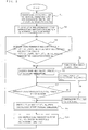
- Fig. 2 is a flowchart representing an exemplary control operation for defrosting performed in the refrigerating air conditioning system.
- step S1 the capacity of the compressor 3, the opening degrees of the first and the second expansion valves 10 and 8 are set to initial values.
- the capacity of the compressor 3 is basically controlled such that the room temperature detected by the seventh temperature sensor 14g of the indoor unit 2 becomes the value set by the user of the refrigerating air conditioning system.
- step S3 the outdoor pipe temperature of the outdoor unit 1 detected by the third temperature sensor 14c as the refrigerant temperature of the evaporator is compared with a predetermined set value for the purpose of detecting the state of the frost formed on the outdoor unit 1 (especially the outdoor heat exchanger 11). As shown in Fig.
- the outdoor pipe temperature is equal to or lower than the set value, for example -5°C or lower
- the outdoor pipe temperature is higher than the temperature detected by the outdoor air sensor (fourth temperature sensor 14d) by 10°C or higher as indicated by the temperature difference ⁇ T between the outdoor air temperature and the outdoor pipe temperature, and the defrosting inhibition time ⁇ 3 (for example, 30 minutes) has elapsed, it is determined that a large amount of the frost is formed on the outdoor heat exchanger 11 as the evaporator.
- the process proceeds to step S4 where the frequency of the compressor 3 is reduced to minimum, for example, 25Hz
- the process proceeds to step S5 where the compressor frequency is reduced to the minimum frequency to start defrosting by switching the four-way valve 4.
- step S6 the compressor frequency is fixed to the defrosting frequency, for example, 92Hz.
- step S7 the outdoor pipe temperature is compared with the predetermined set value.
- the process proceeds to step S8 where the compressor 3 is stopped for one minute.
- step S9 the compressor 3 is restarted by switching the four-way valve 4.
- step S10 the defrosting inhibition time values ⁇ 1 and ⁇ 3 are set in accordance with the defrosting time in step 7 (previous defrosting time) ⁇ 2 so as to continue the heating by inhibiting defrosting.
- the defrosting inhibition time ( ⁇ 1, ⁇ 3) for the next cycle becomes that is, the duration of the heating operation is reduced.
- the defrosting inhibition time is relatively a short so as to improve the heating performance by recovering the performance of the evaporator faster.
- the defrosting inhibition time ( ⁇ 1, ⁇ 3) for the next cycle is changed to be long such that the duration of the heating operation is increased for the purpose of improving the heating comfort.
- the exemplary values of the defrosting inhibition times ⁇ 1 and ⁇ 3 set in accordance with the defrosting time value ⁇ 2 are shown in Fig. 4 . If the defrosting time ⁇ 2 is set to be short, for example, to the value equal to or shorter than 3 minutes, the ⁇ 1 is set to 150 minutes and ⁇ 3 is set to 30 minutes. If the defrosting time ⁇ 2 is set to be long, for example, to 12 minutes, the ⁇ 1 is set to 30 minutes and ⁇ 3 is set to 20 minutes. The defrosting time ⁇ 2 is defined to be set to 15 minutes at maximum. The values of ⁇ 1 and ⁇ 3 are set such that the relationship of ⁇ 1 ⁇ ⁇ 3 is established.
- the defrosting operation is performed with the same cycle as that of the cooling mode.
- the high pressure high temperature refrigerant discharged from the compressor 3 is fed to the outdoor heat exchanger 11 for performing the defrosting. Thereafter, the process returns to step S3 for executing the control routine.
- step 3 in the case where the outdoor pipe temperature is equal to or lower than the predetermined set value, the temperature difference ⁇ T is lower than 10°C, and the defrosting inhibition time ⁇ 1 (for example, 150 minutes) has elapsed, for example, the outdoor pipe temperature becomes -2°C, the process proceeds to steps 4 and 5 to start defrosting.
- the defrosting inhibition time ⁇ 1 is set to relatively a long period, the heating operation may be performed for a long period (150 minutes), thus improving the comfort.
- the evaporation temperature is gradually decreased owing to deterioration in heat transmission property caused by the frost formation, and reduction in air volume caused by the increase in the pressure loss.
- the difference between the outdoor air temperature and the outdoor pipe temperature becomes large.
- the outdoor pipe temperature becomes negative (for example, -5°C or lower), and the temperature is sufficiently lower than the outdoor air temperature (for example, the outdoor pipe temperature is lower than the outdoor air temperature by 10°C or more), it is determined that the amount of the frost formed on the outdoor heat exchanger is large.
- the system operation is switched to the defrosting operation to melt the frost for the purpose of recovering the heat transmitting property of the outdoor heat exchanger serving as the evaporator.
- the decrease rate in the outdoor pipe temperature relative to the outdoor air temperature is small.
- the defrosting inhibition time ⁇ 1 150 minutes in this case
- the outdoor pipe temperature becomes negative, for example, -2°C or lower
- the defrosting inhibition time ⁇ 1 is set to a relatively long period. This allows the heating operation for a long period, thus improving the operation efficiency.
- the defrosting operation for melting the frost formed on the refrigerant pipe of the outdoor heat exchanger 11 by the refrigerant heat during heating operation is performed by feeding the refrigerant by switching the four-way valve 4 likewise the cooling operation.
- the frequency of the compressor 3 is fixed to the defrosting frequency which is higher than a rated frequency.
- the flow rate of the refrigerant discharged from the compressor 3 increases to further increase the flow rate of the refrigerant flowing into the outdoor heat exchanger 11 as the evaporator. This makes it possible to reduce the defrosting time.
- the compressor 3 is temporarily stopped when switching the mode to the heating operation after completion of the defrosting. Thereby, the four-way valve 4 may be reliably switched at a small pressure difference between the high and low pressures. The resultant vibration and noise of the refrigerant may also be suppressed.
- the third temperature sensor 14c is used as the means for detecting the refrigerant temperature of the evaporator during the heating operation.
- the same effect can, of course, be obtained by using the second temperature sensor 14b instead of the third temperature sensor or together therewith.
- the R410A is employed as the refrigerant, the same effect can, of course, be obtained by using other refrigerant.
Landscapes
- Engineering & Computer Science (AREA)
- Physics & Mathematics (AREA)
- Mechanical Engineering (AREA)
- Thermal Sciences (AREA)
- General Engineering & Computer Science (AREA)
- Air Conditioning Control Device (AREA)
Claims (3)
- Kälteklimatisierungssystem, ausgestattet mit einem Kältemittelkreislauf, der einen Verdichter (3), einen Innenwärmetauscher (6), eine erste Druckreduzierungseinrichtung (10), einen Außenwärmetauscher (11) und eine Schalteinrichtung (4) zum Schalten einer Richtung eines Kältemittelstroms zwischen Erwärmungs- und Kühlungsmodi zum Zuführen von Wärme aus dem Innenwärmetauscher (6) aufweist, Außenleitungskältemitteltemperaturerfassungsmittel (14c) des Au-ßenwärmetauschers (11), um eine Außenleitungstemperatur, die einer Kältemitteltemperatur des Außenwärmetauschers (11) entspricht, zu erfassen, dadurch gekennzeichnet, dass
ein Außenlufttemperaturerfassungsmittel (14d), um eine Außenlufttemperatur zu erfassen, vorgesehen ist zum Bestimmen eines Zustands von am Außenwärmetauscher (11) gebildeten Frost;
zwei Arten von Entfrostungshemmungszeitwerten τ1 und τ3, welche entsprechend einer vorherigen Entfrostungszeit τ2 zum kontinuierlichen Durchführen eines Erwärmungsbetriebs einstellbar sind;
eine Messungssteuerungseinheit (12), durchführend einen Entfrostungsbetrieb, indem die Entfrostungshemmungszeitwerte τ1, τ3 so gesteuert werden, dass sie lang sind, wenn eine Menge des am Außenwärmetauscher (11) gebildeten Frostes auf Grundlage von der vorherigen Entfrostungszeit τ2 als klein bestimmt wird, und dass die Entfrostungshemmungszeitwerte τ1, τ3, kurz sind, wenn die Menge des am Außenwärmetauscher (11) gebildeten Frostes auf Grundlage von der vorherigen Entfrostungszeit τ2 als groß bestimmt wird,
wobei die zwei Arten von Entfrostungshemmungszeitwerten τ1 und τ3 korreliert sind, um eine Beziehung von τ1 ≥ τ3 herzustellen; wenn die am Außenwärmetauscher (11) gebildete Frostmenge als klein bestimmt wird auf Grundlage von den durch die Außenleitungskältemitteltemperaturerfassungsmittel (14c) und das Außenlufttemperaturerfassungsmittel (14d) erfassten Temperaturen, eine Bestimmung in Bezug auf das Schalten auf einen Entfrostungsbetrieb durchgeführt wird auf Grundlage von den Außenleitungstemperaturerfassungsmitteln (14c) und der Entfrostungshemmungszeit τ1; und
wenn die am Außenwärmetauscher (11) gebildete Frostmenge als groß bestimmt wird auf Grundlage von den durch die Außenleitungskältemitteltemperaturerfassungsmittel (14c) und das Außenlufttemperaturerfassungsmittel (14d) erfassten Temperaturen, die Bestimmung in Bezug auf das Schalten auf einen Entfrostungsbetrieb durchgeführt wird auf Grundlage von den Außenleitungskältemitteltemperaturerfassungsmitteln (14c), einem Außenlufttemperaturerfassungsmittel (14d) und dem Entfrostungshemmungszeitwert τ3. - Kälteklimatisierungssystem nach Anspruch 1, dadurch gekennzeichnet, dass zwischen dem Innenwärmetauscher (6) und der ersten Druckreduzierungseinrichtung (10) ein Mitteldruckaufnehmer (9) vorgesehen ist und zwischen dem Innenwärmetauscher (6) und dem Mitteldruckaufnehmer (10) eine zweite Druckreduzierungseinrichtung (8) vorgesehen ist.
- Kälteklimatisierungssystem nach Anspruch 2, dadurch gekennzeichnet, dass eine Steuereinrichtung vorgesehen ist, in welcher:die stromabwärts des Mitteldruckaufnehmers (9) angeordnete Druckreduzierungseinrichtung einen Strom des Kältemittels steuert, so dass einer von einem Überhitzungsgrad des Kältemittels, das in den Verdichter (3) eingesaugt wird, einem Überhitzungsgrad des Kältemittels an einem Auslass des Wärmetauschers, der als ein Kondensator dient, einer Ablasstemperatur des Verdichters (3) und dem Überhitzungsgrad des Kältemittels, das aus dem Verdichter (3) ausgelassen wird, zu einem vorherbestimmten Zielwert wird; unddie stromaufwärts des Mitteldruckaufnehmers (9) angeordnete Druckreduzierungseinrichtung den Strom des Kältemittels steuert, so dass der Unterkühlungsgrad am Auslass des Wärmetauschers, der als ein Kondensator dient, zu einem vorherbestimmten Zielwert wird.
Applications Claiming Priority (2)
| Application Number | Priority Date | Filing Date | Title |
|---|---|---|---|
| JP2005215878 | 2005-07-26 | ||
| PCT/JP2006/314541 WO2007013382A1 (ja) | 2005-07-26 | 2006-07-24 | 冷凍空調装置 |
Publications (3)
| Publication Number | Publication Date |
|---|---|
| EP1826513A1 EP1826513A1 (de) | 2007-08-29 |
| EP1826513A4 EP1826513A4 (de) | 2009-04-22 |
| EP1826513B1 true EP1826513B1 (de) | 2019-10-23 |
Family
ID=37683279
Family Applications (1)
| Application Number | Title | Priority Date | Filing Date |
|---|---|---|---|
| EP06781463.2A Not-in-force EP1826513B1 (de) | 2005-07-26 | 2006-07-24 | Kühlende klimaanlage |
Country Status (5)
| Country | Link |
|---|---|
| US (1) | US7856836B2 (de) |
| EP (1) | EP1826513B1 (de) |
| JP (1) | JP5063347B2 (de) |
| CN (1) | CN100465555C (de) |
| WO (1) | WO2007013382A1 (de) |
Families Citing this family (48)
| Publication number | Priority date | Publication date | Assignee | Title |
|---|---|---|---|---|
| DE10315523A1 (de) * | 2003-04-04 | 2004-10-14 | BSH Bosch und Siemens Hausgeräte GmbH | Kältegerät mit adaptiver Abtauautomatik und Abtauverfahren dafür |
| DE10315524A1 (de) * | 2003-04-04 | 2004-10-14 | BSH Bosch und Siemens Hausgeräte GmbH | Kältegerät und Betriebsverfahren dafür |
| JP2008224135A (ja) * | 2007-03-13 | 2008-09-25 | Mitsubishi Electric Corp | 冷凍装置 |
| JP4666061B2 (ja) * | 2008-11-17 | 2011-04-06 | ダイキン工業株式会社 | 空気調和装置 |
| US8452459B2 (en) * | 2009-08-31 | 2013-05-28 | Fisher-Rosemount Systems, Inc. | Heat exchange network heat recovery optimization in a process plant |
| CN102012138B (zh) * | 2009-09-04 | 2012-11-07 | 海尔集团公司 | 一种空调器及控制其进行除霜运行的方法 |
| CN101806519B (zh) * | 2010-04-19 | 2012-07-11 | 广东吉荣空调有限公司 | 具有防霜功能的宽温高效空气源热泵机组及其运行方法 |
| US9927157B2 (en) * | 2010-06-02 | 2018-03-27 | Dwayne M. Benson | Integrated power, cooling, and heating device and method thereof |
| US9222372B2 (en) | 2010-06-02 | 2015-12-29 | Dwayne M Benson | Integrated power, cooling, and heating apparatus utilizing waste heat recovery |
| WO2012003202A2 (en) * | 2010-07-01 | 2012-01-05 | Carrier Corporation | Evaporator refrigerant saturation demand defrost |
| EP2685181B1 (de) * | 2011-03-07 | 2020-05-20 | Mitsubishi Electric Corporation | Klimaanlage |
| CN102141334B (zh) * | 2011-04-22 | 2016-06-22 | 张明亮 | 制冷设备翅片结霜检测装置及其应用的自动化霜装置 |
| CN102331119A (zh) * | 2011-08-04 | 2012-01-25 | 广东美的电器股份有限公司 | 空调器及其除霜控制方法 |
| CN102384558B (zh) * | 2011-10-18 | 2013-07-03 | 集美大学 | 用于直接膨胀式变风量空调系统的能力控制方法 |
| EP2786081A1 (de) * | 2011-12-02 | 2014-10-08 | Kysor Panel Systems Division of Welbilt Walk-Ins, LP | Kühlvorrichtung und -verfahren |
| US9383126B2 (en) * | 2011-12-21 | 2016-07-05 | Nortek Global HVAC, LLC | Refrigerant charge management in a heat pump water heater |
| CN103827593B (zh) * | 2011-12-26 | 2017-03-15 | 松下电器产业株式会社 | 空气调节机 |
| CN102538300B (zh) * | 2012-02-14 | 2014-10-01 | 青岛海尔空调电子有限公司 | 风冷热泵机组、板式换热器的防冻方法 |
| US9239183B2 (en) | 2012-05-03 | 2016-01-19 | Carrier Corporation | Method for reducing transient defrost noise on an outdoor split system heat pump |
| JP5897994B2 (ja) * | 2012-06-06 | 2016-04-06 | シャープ株式会社 | 空気調和機 |
| JP5516695B2 (ja) * | 2012-10-31 | 2014-06-11 | ダイキン工業株式会社 | 空気調和装置 |
| SE537022C2 (sv) * | 2012-12-21 | 2014-12-09 | Fläkt Woods AB | Förfarande och anordning för avfrostning av en förångare vidett luftbehandlingsaggregat |
| JP6137461B2 (ja) * | 2013-03-29 | 2017-05-31 | 株式会社富士通ゼネラル | 空気調和機 |
| JP6137462B2 (ja) * | 2013-03-29 | 2017-05-31 | 株式会社富士通ゼネラル | 空気調和機 |
| JP2014202367A (ja) * | 2013-04-01 | 2014-10-27 | 株式会社デンソー | 冷凍サイクル装置 |
| JP5590195B1 (ja) | 2013-07-11 | 2014-09-17 | 株式会社富士通ゼネラル | 空気調和装置 |
| JP5574028B1 (ja) * | 2013-07-31 | 2014-08-20 | 株式会社富士通ゼネラル | 空気調和装置 |
| CN103542651B (zh) * | 2013-08-26 | 2016-06-15 | 宁波奥克斯空调有限公司 | 一种热泵空调除霜的控制方法 |
| JP5549771B1 (ja) * | 2013-09-12 | 2014-07-16 | 株式会社富士通ゼネラル | 空気調和装置 |
| JP5786914B2 (ja) * | 2013-09-30 | 2015-09-30 | ダイキン工業株式会社 | 空気調和装置 |
| JP5929862B2 (ja) * | 2013-09-30 | 2016-06-08 | ダイキン工業株式会社 | 空気調和装置 |
| JP6201872B2 (ja) * | 2014-04-16 | 2017-09-27 | 三菱電機株式会社 | 空気調和機 |
| JP5999171B2 (ja) * | 2014-12-26 | 2016-09-28 | ダイキン工業株式会社 | 空気調和装置 |
| JP2016161256A (ja) * | 2015-03-04 | 2016-09-05 | 株式会社富士通ゼネラル | 空気調和装置 |
| JP6346122B2 (ja) * | 2015-04-23 | 2018-06-20 | 株式会社コロナ | 温水暖房システム |
| CN107923666B (zh) | 2015-08-14 | 2020-08-14 | 丹佛斯有限公司 | 具有至少两个蒸发器组的蒸气压缩系统 |
| CN108139132B (zh) | 2015-10-20 | 2020-08-25 | 丹佛斯有限公司 | 用于控制有可变接收器压力设定点的蒸气压缩系统的方法 |
| MX2018004604A (es) * | 2015-10-20 | 2018-07-06 | Danfoss As | Metodo para controlar un sistema de compresion de vapor en modo de eyector durante un tiempo prolongado. |
| CN108027185B (zh) | 2015-10-27 | 2020-06-05 | 株式会社电装 | 制冷循环装置 |
| CN106500248B (zh) * | 2016-10-31 | 2019-11-26 | 广东美的制冷设备有限公司 | 空调器加热管开启时间控制方法、控制器及空调器 |
| SE540735C2 (sv) * | 2017-03-31 | 2018-10-23 | Flaektgroup Sweden Ab | Metod för att motverka uppbyggnad av frost på en värmeåtervinnare anordnad vid ett luftbehandlingsaggregat |
| JP7049148B2 (ja) * | 2018-03-28 | 2022-04-06 | 三菱重工サーマルシステムズ株式会社 | 制御装置、空気調和機、制御方法及びプログラム |
| DK180146B1 (en) | 2018-10-15 | 2020-06-25 | Danfoss As Intellectual Property | Heat exchanger plate with strenghened diagonal area |
| CN109357343B (zh) * | 2018-10-24 | 2021-06-29 | 青岛海尔空调器有限总公司 | 空调器 |
| JP7409105B2 (ja) * | 2020-01-20 | 2024-01-09 | 株式会社デンソー | 空調システムおよび空調制御方法 |
| CN112303816B (zh) * | 2020-09-29 | 2021-12-14 | 东风汽车集团有限公司 | 一种室外换热器结霜识别方法及除霜控制方法 |
| CN114264094B (zh) * | 2021-12-15 | 2023-03-21 | 珠海格力电器股份有限公司 | 一种化霜控制方法及制冷系统 |
| CN115727479B (zh) * | 2022-11-24 | 2024-08-06 | 珠海格力电器股份有限公司 | 基于物联网的化霜判断方法及空调机组 |
Family Cites Families (16)
| Publication number | Priority date | Publication date | Assignee | Title |
|---|---|---|---|---|
| US4694657A (en) * | 1979-06-20 | 1987-09-22 | Spectrol Electronics Corporation | Adaptive defrost control and method |
| JPS57164245A (en) | 1981-03-31 | 1982-10-08 | Mitsubishi Heavy Ind Ltd | Air conditioner |
| JPS60218551A (ja) | 1984-04-13 | 1985-11-01 | Sharp Corp | ヒ−トポンプ式空気調和機の除霜装置 |
| JPS63286676A (ja) * | 1987-05-18 | 1988-11-24 | 三菱電機株式会社 | 空気調和装置 |
| JPH01134146A (ja) * | 1987-11-18 | 1989-05-26 | Mitsubishi Electric Corp | 空気調和機の霜取り装置 |
| JP3893676B2 (ja) * | 1996-08-08 | 2007-03-14 | 株式会社日立製作所 | 空気調和装置 |
| KR100225640B1 (ko) | 1997-06-27 | 1999-10-15 | 윤종용 | 공기조화기의 제상제어방법 |
| JP3609286B2 (ja) * | 1999-05-25 | 2005-01-12 | シャープ株式会社 | 空調機器 |
| JP3593592B2 (ja) * | 1999-09-30 | 2004-11-24 | 株式会社日立製作所 | 空気調和機 |
| JP2002318039A (ja) | 2001-04-20 | 2002-10-31 | Hitachi Ltd | 空気調和機 |
| JP3879458B2 (ja) * | 2001-08-28 | 2007-02-14 | 株式会社日立製作所 | 空気調和装置 |
| JP2004093020A (ja) | 2002-08-30 | 2004-03-25 | Chofu Seisakusho Co Ltd | ヒートポンプエアコンの除霜運転制御方法 |
| JP3852591B2 (ja) * | 2002-09-24 | 2006-11-29 | 三菱電機株式会社 | 冷凍サイクル |
| JP4100135B2 (ja) * | 2002-11-07 | 2008-06-11 | 三菱電機株式会社 | 冷凍サイクル装置及び冷凍サイクル装置の制御方法 |
| US6851270B2 (en) * | 2003-06-09 | 2005-02-08 | Texas Instruments Incorporated | Integrated refrigeration control |
| WO2007110908A1 (ja) | 2006-03-27 | 2007-10-04 | Mitsubishi Denki Kabushiki Kaisha | 冷凍空調装置 |
-
2006
- 2006-07-24 CN CNB2006800010755A patent/CN100465555C/zh not_active Expired - Fee Related
- 2006-07-24 JP JP2007528444A patent/JP5063347B2/ja not_active Expired - Fee Related
- 2006-07-24 US US11/662,519 patent/US7856836B2/en not_active Expired - Fee Related
- 2006-07-24 EP EP06781463.2A patent/EP1826513B1/de not_active Not-in-force
- 2006-07-24 WO PCT/JP2006/314541 patent/WO2007013382A1/ja active Application Filing
Non-Patent Citations (1)
| Title |
|---|
| None * |
Also Published As
| Publication number | Publication date |
|---|---|
| WO2007013382A1 (ja) | 2007-02-01 |
| JP5063347B2 (ja) | 2012-10-31 |
| EP1826513A4 (de) | 2009-04-22 |
| CN101052848A (zh) | 2007-10-10 |
| JPWO2007013382A1 (ja) | 2009-02-05 |
| US7856836B2 (en) | 2010-12-28 |
| EP1826513A1 (de) | 2007-08-29 |
| US20090266093A1 (en) | 2009-10-29 |
| CN100465555C (zh) | 2009-03-04 |
Similar Documents
| Publication | Publication Date | Title |
|---|---|---|
| EP1826513B1 (de) | Kühlende klimaanlage | |
| JP4459776B2 (ja) | ヒートポンプ装置及びヒートポンプ装置の室外機 | |
| JP5575192B2 (ja) | 二元冷凍装置 | |
| JP5575191B2 (ja) | 二元冷凍装置 | |
| EP2479519B1 (de) | Kühlsystem | |
| US20110174005A1 (en) | Refrigerating apparatus | |
| JP2008032336A (ja) | 二段膨張冷凍装置 | |
| JP2009270822A (ja) | ヒートポンプ装置及びヒートポンプ装置の室外機 | |
| JP4462435B2 (ja) | 冷凍装置 | |
| JP2008224135A (ja) | 冷凍装置 | |
| JP6420686B2 (ja) | 冷凍サイクル装置 | |
| JP4760974B2 (ja) | 冷凍装置 | |
| JP2008096033A (ja) | 冷凍装置 | |
| JP2006177597A (ja) | 冷凍装置及びこれを用いた空気調和機 | |
| WO2012169182A1 (ja) | 冷凍装置 | |
| EP2918921B1 (de) | Heisswassererzeuger | |
| JP2008138915A (ja) | 冷凍装置 | |
| JP2008267691A (ja) | 空気調和装置 | |
| CN115560496A (zh) | 喷气增焓热泵冷水系统及控制方法 | |
| WO2021033426A1 (ja) | 熱源ユニット及び冷凍装置 | |
| JPH1038387A (ja) | 空気調和機の運転制御装置 | |
| WO2020179005A1 (ja) | 冷凍サイクル装置 | |
| JP2002228284A (ja) | 冷凍装置 | |
| JP4318369B2 (ja) | スクリュー式冷凍機 | |
| JP2004205142A (ja) | 冷凍空調装置およびその運転制御方法 |
Legal Events
| Date | Code | Title | Description |
|---|---|---|---|
| PUAI | Public reference made under article 153(3) epc to a published international application that has entered the european phase |
Free format text: ORIGINAL CODE: 0009012 |
|
| 17P | Request for examination filed |
Effective date: 20070319 |
|
| AK | Designated contracting states |
Kind code of ref document: A1 Designated state(s): AT BE BG CH CY CZ DE DK EE ES FI FR GB GR HU IE IS IT LI LT LU LV MC NL PL PT RO SE SI SK TR |
|
| AX | Request for extension of the european patent |
Extension state: AL BA HR MK YU |
|
| DAX | Request for extension of the european patent (deleted) | ||
| DAX | Request for extension of the european patent (deleted) | ||
| RBV | Designated contracting states (corrected) |
Designated state(s): DE FR IT SE |
|
| A4 | Supplementary search report drawn up and despatched |
Effective date: 20090324 |
|
| 17Q | First examination report despatched |
Effective date: 20090619 |
|
| GRAP | Despatch of communication of intention to grant a patent |
Free format text: ORIGINAL CODE: EPIDOSNIGR1 |
|
| RIC1 | Information provided on ipc code assigned before grant |
Ipc: F25D 21/00 20060101ALN20190410BHEP Ipc: F25B 47/02 20060101AFI20190410BHEP |
|
| INTG | Intention to grant announced |
Effective date: 20190430 |
|
| RIC1 | Information provided on ipc code assigned before grant |
Ipc: F25B 47/02 20060101AFI20190415BHEP Ipc: F25D 21/00 20060101ALN20190415BHEP |
|
| GRAS | Grant fee paid |
Free format text: ORIGINAL CODE: EPIDOSNIGR3 |
|
| GRAA | (expected) grant |
Free format text: ORIGINAL CODE: 0009210 |
|
| AK | Designated contracting states |
Kind code of ref document: B1 Designated state(s): DE FR IT SE |
|
| REG | Reference to a national code |
Ref country code: DE Ref legal event code: R096 Ref document number: 602006058734 Country of ref document: DE |
|
| REG | Reference to a national code |
Ref country code: SE Ref legal event code: TRGR |
|
| REG | Reference to a national code |
Ref country code: DE Ref legal event code: R097 Ref document number: 602006058734 Country of ref document: DE |
|
| PLBE | No opposition filed within time limit |
Free format text: ORIGINAL CODE: 0009261 |
|
| STAA | Information on the status of an ep patent application or granted ep patent |
Free format text: STATUS: NO OPPOSITION FILED WITHIN TIME LIMIT |
|
| 26N | No opposition filed |
Effective date: 20200724 |
|
| PGFP | Annual fee paid to national office [announced via postgrant information from national office to epo] |
Ref country code: SE Payment date: 20220615 Year of fee payment: 17 Ref country code: IT Payment date: 20220613 Year of fee payment: 17 |
|
| PGFP | Annual fee paid to national office [announced via postgrant information from national office to epo] |
Ref country code: FR Payment date: 20220609 Year of fee payment: 17 |
|
| PGFP | Annual fee paid to national office [announced via postgrant information from national office to epo] |
Ref country code: DE Payment date: 20220531 Year of fee payment: 17 |
|
| REG | Reference to a national code |
Ref country code: DE Ref legal event code: R119 Ref document number: 602006058734 Country of ref document: DE |
|
| REG | Reference to a national code |
Ref country code: SE Ref legal event code: EUG |
|
| PG25 | Lapsed in a contracting state [announced via postgrant information from national office to epo] |
Ref country code: DE Free format text: LAPSE BECAUSE OF NON-PAYMENT OF DUE FEES Effective date: 20240201 |
|
| PG25 | Lapsed in a contracting state [announced via postgrant information from national office to epo] |
Ref country code: SE Free format text: LAPSE BECAUSE OF NON-PAYMENT OF DUE FEES Effective date: 20230725 Ref country code: FR Free format text: LAPSE BECAUSE OF NON-PAYMENT OF DUE FEES Effective date: 20230731 |
|
| PG25 | Lapsed in a contracting state [announced via postgrant information from national office to epo] |
Ref country code: IT Free format text: LAPSE BECAUSE OF NON-PAYMENT OF DUE FEES Effective date: 20230724 |