EP1825976B1 - Verfahren und Vorrichtung zum Bestimmen der optimalen Schälachse eines Baumstammes sowie dessen Punkt mit Maximalradius mit Bezug auf die Schälachse - Google Patents
Verfahren und Vorrichtung zum Bestimmen der optimalen Schälachse eines Baumstammes sowie dessen Punkt mit Maximalradius mit Bezug auf die Schälachse Download PDFInfo
- Publication number
- EP1825976B1 EP1825976B1 EP06110523A EP06110523A EP1825976B1 EP 1825976 B1 EP1825976 B1 EP 1825976B1 EP 06110523 A EP06110523 A EP 06110523A EP 06110523 A EP06110523 A EP 06110523A EP 1825976 B1 EP1825976 B1 EP 1825976B1
- Authority
- EP
- European Patent Office
- Prior art keywords
- log
- axis
- contact surfaces
- preliminary
- optimum peeling
- Prior art date
- Legal status (The legal status is an assumption and is not a legal conclusion. Google has not performed a legal analysis and makes no representation as to the accuracy of the status listed.)
- Expired - Lifetime
Links
Images


Classifications
-
- B—PERFORMING OPERATIONS; TRANSPORTING
- B27—WORKING OR PRESERVING WOOD OR SIMILAR MATERIAL; NAILING OR STAPLING MACHINES IN GENERAL
- B27L—REMOVING BARK OR VESTIGES OF BRANCHES; SPLITTING WOOD; MANUFACTURE OF VENEER, WOODEN STICKS, WOOD SHAVINGS, WOOD FIBRES OR WOOD POWDER
- B27L5/00—Manufacture of veneer ; Preparatory processing therefor
- B27L5/02—Cutting strips from a rotating trunk or piece; Veneer lathes
- B27L5/022—Devices for determining the axis of a trunk ; Loading devices for veneer lathes
Definitions
- the present invention relates to a method of locating the optimum peeling axis of a peeler log for maximum yield in veneer production by a rotary veneer lathe and also locating the maximum radius point of the log's peripheral surface with respect to the located optimum peeling axis.
- the invention also relates to an apparatus for performing the method.
- a typical apparatus for determining the location of the optimum peeling axis of a log and the maximum radius point thereof is disclosed by the Unexamined Japanese Patent Application Publication (or KOKAI Publication) No. H6-293002 ( US-A-5 449 030 ).
- This apparatus has a number of log profile detectors which are disposed very close to each other along the entire length of a log for detecting the cross-sectional profiles of the log at many positions thereof along the log length while the log is rotated for a complete turn about its preliminary axis.
- the location of the optimum peeling axis of the log is determined on the basis of the information of the detected cross-sectional profiles at at least two positions.
- the point on the log peripheral surface having the maximum radius with respect to the located optimum peeling axis is determined based on the information of cross-sectional profiles detected at all positions.
- a rotary veneer lathe for peeling a log for production of veneer
- the log supported or held at its opposite ends by lathe spindles is rotated about its longitudinal axis.
- a veneer knife mounted in a movable knife carriage is advanced toward the lathe spindles to cut into the log surface for a distance corresponding to the desired thickness of veneer to be peeled from the log for each complete turn of the log.
- the knife carriage If the knife carriage is located too far from the lathe spindles and hence the cutting edge of the veneer knife is positioned far from the log periphery just before the peeling operation is started, it takes a long time before the cutting edge of the knife reaches the log peripheral surface and actual veneer peeling begins, with the result that non-cutting downtime is increased and, therefore, the productivity in veneer production is affected thereby.
- the location on the log surface which has the maximum radius point should be determined previously and the knife carriage is positioned accordingly so that the veneer knife cuts into the log surface immediately.
- An object of the present invention is to provide a method and an apparatus which can solve the drawbacks of the above-described prior art apparatus.
- a method of locating an optimum peeling axis of a log and a maximum radius point on peripheral surface of the log with respect to said optimum peeling axis on the basis of information of peripheral profile of the log which is rotated about a preliminary axis thereof for at least one complete turn comprising:
- said determining of the maximum radius point of the log is performed by computing radial distances of the log from a plurality of predetermined locations on said computed optimum peeling axis to selected contact surfaces on the basis of the measured angular positions of the contact surfaces along imaginary lines extending perpendicularly to said optimum peeling axis and comparing said computed radial distances to recognise the distance having the greatest value as the maximum radius point of the log.
- the predetermined locations on the computed optimum peeling axis correspond to the points of intersection between the optimum peeling axis and respective imaginary planes extending across the log at a side of the width of the contact surfaces in perpendicular relation to the preliminary axis of the log.
- angles of any two adjacent contact surfaces with respect to the reference position are compared on the basis of the angular positions of such two adjacent contact surfaces measured at each of the predetermined angularly spaced positions of the log and the above selected contact surfaces include one of the two adjacent contact surfaces whose angle with respect to the reference position is larger than that of the other of the two adjacent contact surfaces.
- the above predetermined locations on the computed optimum peeling axis may be the points of intersection between the optimum peeling axis and respective imaginary planes extending across the log at a substantial center of the width of the contact surfaces in perpendicular relation to said preliminary axis of the log.
- An apparatus of the present invention for performing the above method comprises:
- control means may be operable to compute radial distances of the log from a plurality of predetermined locations on said computed optimum peeling axis to selected contact surfaces on the basis of the measured angular positions of the contact surfaces along imaginary lines extending perpendicularly to said computed optimum peeling axis and to compare said computed radial distances to recognise the distance having the greatest value as the maximum radius point of the log.
- the control means is also operable to compare angles of any two adjacent contact surfaces with respect to the reference position on the basis of the angular positions of such two adjacent contact surfaces measured at each of the predetermined angularly spaced positions of the log so that the radial distance of the log from the predetermined location on the optimum peeling axis to the selected contact surface whose angle with respect to said reference position is larger than that of the other of said two adjacent contact surfaces.
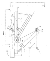
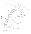
- the apparatus has a pair of spindles 3 which are mounted rotatably in the frame (not shown) of the apparatus.
- the spindles 3 are movable toward and away from each other as indicated by arrows Z for holding therebetween a peeler log W (shown, e.g. in FIG. 5 ) at a preliminary axis thereof which corresponds to the aligned longitudinal axes 3b of the paired spindles 3.
- the servo motor 5 is operatively connected to at least one of the spindles 3 so that the log W is driven to rotate by the spindles.
- the servo motor 5 is also connected to a rotary encoder 7 which is operable to monitor and determine angular positions of the spindles 3 connected to the servo motor 5 and hence angular positions of the log W in rotation and then to generate to a control unit 20 electrical signals indicative of the angular position of the log W.
- a rotary encoder 7 operable to monitor and determine angular positions of the spindles 3 connected to the servo motor 5 and hence angular positions of the log W in rotation and then to generate to a control unit 20 electrical signals indicative of the angular position of the log W.
- the reference symbol 3b for the aligned longitudinal axes of the paired spindles 3 shall also refers to an imaginary longitudinal axial line connecting the aligned axes of the spindles 3 and further to the preliminary axis of the log W as shown in FIGS. 3 and 5 .
- the apparatus further has three laser-operated devices 9a, 9b, 9c which are provided at locations spaced along the longitudinal axial line 3b as shown in FIGS. 1 and 3 .
- the laser devices 9a and 9c are located adjacently to the respective longitudinal ends of the log W when it is held between the spindles 3 and the laser device 9b is located between the two laser devices 9a and 9c.
- the laser devices 9a, 9b, 9c are spaced away from the longitudinal axial line 3b at a predetermined distance L1.
- Each laser device 9a, 9b, 9c has a light source for emitting a laser beam toward the longitudinal axial line 3b and a light receiver for receiving a laser beam reflected from the outer peripheral surface of the log W then held by the spindles 3, thereby to measure the distances L2 (shown in FIG. 6 ) between the laser device 9a, 9b, 9c and a peripheral point of the log surface from which the laser beam has been reflected.
- These distance measuring laser devices 9a, 9b, 9c are connected to the control unit 20 and provide information of the measured distances L2 to the control unit 20 which is operable to compute or figure out radial distances of the log W between the longitudinal axial line 3b and the peripheral points of the log surface by subtracting the measured distances L2 from the predetermined distance L1. Repeating such calculation on the basis of distance measurements at a number of angularly spaced positions of the log W, the control unit 20 computes to determine the peripheral profiles of the log W, as will be described in later part hereof.
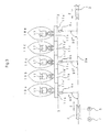
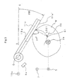
- the apparatus further has a number of swing arms.
- five swing arms 10a, 10b, 10c, 10d, 10e are shown, e.g. in FIGS. 2 and 3 , which are juxtaposed at a predetermined spaced interval on a support shaft 13 fixedly mounted to the frame (not shown) of the apparatus and having a longitudinal axis O extending in parallel to the longitudinal axial line 3b, as shown in FIG. 1 .
- the arms 10a, 10b, 10c, 10d, 10e are pivotally mounted on the support shaft for swinging about the axis O.
- the swing arms 10a, 10b, 10c, 10d, 10e have fixedly attached thereto contact plates 11a, 11b, 11c, 11d, 11e which have flat contact surfaces 11a', 11b', 11c', 11 d', 11e', respectively, extending in parallel to the axis O of the arm support shaft 13 and contactable with the peripheral surface of a log W held between the spindles 3.
- the contact surfaces 11a', 11b', 11c', 11d', 11e' of the contact plates 11a, 11b, 11c, 11d, 11e have substantially the same width extending along the axis O of the support shaft 13.
- Suitable spacers 15 are provided on the arm support shaft 13 for positioning the swing arms 10a, 10b, 10c, 14d, 10e such that the contact plates 11a, 11b, 11c, 11d, 11e are disposed as close to each other as possible while ensuring uninterrupted swinging motion of the arms without interfering with each other.
- each swing arm 10a, 10b, 10c, 10d, 10e is connected to a piston rod 17a of an air-operated cylinder 17 whose end opposite to the piston rod 17a is rotatably mounted to the frame (not shown) of the apparatus so that extending and retracting movement of the piston rod 17a of the air cylinder 17 causes its associated arm to swing as indicated by double-headed arrow in FIG. 1 .
- each swing arm 10a, 10b, 10c, 10d, 10e With the piston rod 17 fully retracted in the air cylinder 17, each swing arm 10a, 10b, 10c, 10d, 10e is placed in its standby position where the contact surface 11 a', 11b', 11c', 11d', 11e' of its contact plate 11a, 11b, 11c, 11d, 11e lies in an imaginary horizontal plane X-X which passes through the axis O of the support shaft 13, as shown in FIGS. 1 and 3 .
- each air cylinder 17 has a length that is large enough for the contact surface 11a' 11b', 11c', 11d', 11e' of the contact plate 11a, 11b, 11c, 11d, 11e to follow the peripheral profile of a log W supported between the spindles 3 while in contact therewith when the log W is rotated about its preliminary axis 3b with air pressure continued to be applied to the piston rod 17a for extension thereof.
- the above standby position X-X of the swing arm 10a, 10b, 10c, 10d, 10e is merely an arbitrary position which is angularly spaced from an imaginary plane extending through the preliminary axis 3b and the longitudinal axis O at an angular distance that is large enough for the contact plate to be clear of a log W held between the spindles 3 and that the imaginary plane passing through the preliminary axis 3b and the longitudinal axis O is a reference position of the apparatus.
- Each swing arm 10a, 10b, 10c, 10d, 10e is operatively connected to a rotary encoder 19a, 19b, 19c, 19d, 19e, as shown in FIGS. 1 and 2 , which is operable to monitor and measure angular positions of each swing arm 10a, 10b, 10c, 10d, 10e and then to transmit to the control unit 20 electrical signals that are representative of the measured angular positions of the swing arm.
- the angular positions of the swing arms 10 a, 10b, 10c, 10d, 10e and hence of the contact surfaces 11a', 11b', 11c', 11d', 11e' are determinable with respect to the above-defined reference position.
- the rotary encoders 19a, 19b, 19c, 19d, 19e are operable to measure angular positions of the contact surfaces with respect to the reference position by determining the angular position with respect to the aforementioned standby position defined by the horizontal plane X-X.
- each contact surface which follows an irregular peripheral profile of the log W in contact therewith is varied as the log W is rotated about its preliminary axis 3b and the contact surface is swung reciprocally up and down according to the irregularities of the log peripheral surface.
- the control unit 20 is operable to compute to figure out angles ⁇ (shown FIG. 6 ) which the contact surfaces 11a', 11b' , 11c', 11d', 11e' have swung from the standby position during the rotation of the log W.
- the control unit 20 is operable to figure out an angle made between the contact surface and the reference position defined by the imaginary plane passing through the axes 3b and O on the basis of the same information.
- the control unit 20 is also operable to generate various control or command signals for controlling the operation of the servo motor 5 and cylinders 17 and also to compute the optimum peeling axis of the peeler log W and the maximum radius point of the log's peripheral surface with respect to the computed optimum peeling axis, as will be described in detail below.
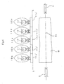
- the piston rods 17a are fully retracted in the cylinders 17, so that the swing arms 10a, 10b, 10c, 10d, 10e are positioned with the contact surfaces 11a', 11b', 11c', 11d', 11e' of their contact plates 11a, 11b, 11c, 11d, 11e placed in the horizontal plane X-X, as shown in FIGS. 1 through 3 .
- a peeler log W is brought and set between the spindles 3b by any suitable log transporting device, as shown in FIG. 4 .
- the control unit 20 Responding to a manual signal provided by machine operator, the control unit 20 generates a command signal which causes the spindles 3 to move toward each other in Z direction thereby to hold or clamp therebetween the peeler log W, as shown in FIG. 5 .
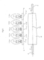
- the cylinders 17 are activated by application of air pressure thereby to extend their piston rods 17a. Accordingly, the arms 10a, 10b, 10c, 10d, 10e are swung downward about the support shaft 13 until the contact surfaces 11a', 11b', 11c', 11d', 11e' are brought into contact with the outer peripheral surface of the log W, as shown in FIGS. 6 and 7 .
- the air pressure continues to be applied to the cylinders 17 and the rotary encoders 19a, 19b, 19c, 19d, 19e make the first measurement of angular positions of the contact surfaces 11a', 11b', 11c', 11d', 11e'.
- the rotary encoders 19a, 19b, 19c, 19d, 19e transmit to the control unit 20 information of the measurement, on the basis of which the control unit 20 figures out the angles ⁇ swung by the respective contact surface 11a', 11b', 11c', 11d', 11e', i.e.
- the angle ⁇ then made between the plane X-X and the plane of the contact surface 11a', 11b', 11c', 11d', 11e', as shown in FIG. 6 , or alternatively the angles made between the contact surface and the aforementioned reference position.
- the distance measuring laser devices 9a, 9b, 9c make the first measurements of the distances L2 and transmit information of the measurements to the control unit 20.
- the control unit 20 figures out the difference between the distances L 1 and L2 thereby to determine the peripheral point on the log surface that is spaced radially from the preliminary axis 3b of the log W.
- the servo motor 5 is started to rotate the spindles 3 and hence the log W in arrow direction ( FIG. 6 ) for at least one complete turn.
- the control unit 20 causes the rotary encoders 19a, 19b, I9c, 19d, 19e to make measurements af the angular positions of the contact surfaces 11a', 11b', 11c', 11d', 11e' and the distance measuring laser devices 9a, 9b, 9c to make measurements of the distances L2, respectively, at a number of angularly spaced positions of the log W in increments of a predetermined angle, e.g. 10°.
- the measurements by each of the rotary encoders 19a, 19b, 19c, 19d, 19e and the laser devices 9a, 9b, 9c are made at a number of peripheral points on the log surface which are substantially equiangularly spaced with respect to the preliminary axis 3b of the log W, e.g. at 36 different peripheral points in the case of the above increment of 10°.
- the control unit 20 computes to figure out the angles ⁇ swung by the respective contact surfaces 11a', 11b', 11c', 11d', 11e' and also the locations of the peripheral points on the log surface as measured from the preliminary axis 3b of the log W, for each of the above equiangularly spaced peripheral points of the log surface in the same manner as in the case of the above-described first measurements.
- the information of the angles ⁇ and the locations of the peripheral points are stored in memory of the control unit 20.
- the cylinders 17 are operated so as to retract their piston rods 17a thereby to restore the swing arms 10a, 10b, 10c, 10d, 10e to their original standby positions, as shown in FIG. 1 , and the control unit 20 is operated to compute to determine the location of the optimum peeling axis HS af the log W ( FIGS. 8 and 9 ) on the basis of the stored information as follows. Firstly, the control unit 20 computes to determine three irregular polygons each of which is formed by connecting the peripheral points on the log surface figured out previously on the base of the measurements by each of the distance measuring laser devices 9a, 9b, 9c. Then, a maximum inscribed circle of each polygon, i.e.
- the largest circle which may be included within the confines of each polygon is computed by the control unit 20.
- a right cylinder which fits within the three inscribed circles is computed in three-dimensional coordinates with reference to a given point, e.g. on the axis O of the support shaft 13 by the control unit 20, and the cylindrical axis of such right cylinder is determined or recognized as the optimum peeling axis HS of the peeler log W.
- the contact surfaces 11a', 11b', 11c', 11d', 11e' follow the peripheral profile of the log W and the swing arms 10a, 10b, 10c, 10d, 10e make an up-and-down swinging motion, as mentioned earlier. It is assumed that the log W is divided into a plurality of log sections corresponding to the width of the respective contact surfaces 11a, 11b, 11c, 11d, 11e, as shown in FIG.
- the swung angles ⁇ for four contact surfaces 11a', 11b', 11c', 11d' are considered to be measured at the imaginary cross-sectional planes A1, A2, A3, A4 of the log W, and the swung angle ⁇ for the contact surface 11e' at the imaginary cross-sectional planes A5 and A6, respectively.
- the control unit 20 compares the swung angles ⁇ of such two adjacent contact surfaces and selects the angle of a smaller value for storage in memory of the control unit 20.
- the reason for selecting the smaller value will be described in later part hereof. Accordingly, for the first sectional plane A1, the swung angle of the first contact surface 11a' is selected for storage in memory.
- the swung angles of the first and second contact surfaces 11 a' and 11 b' are compared and a value determined to be smaller by comparison is selected and stored in memory.
- the swung angles of the two adjacent contact surfaces are compared and a value determined as smaller by comparison is selected for storage in memory.
- the swung angle of the fifth contact surface 11e' is stored in memory of the control unit 20.
- the control unit 20 computes to figure out a radial distance of the log W from a predetermined location on the computed optimum peeling axis HS to each of those contact surfaces whose swung angles were selected and stored in memory of the control unit 20 for being determined through comparison to be smaller than the angle of the adjacent contact surface.
- the above predetermined location on the computed optimum peeling axis HS is a point of intersection between the optimum peeling axis HS and each of the respective imaginary cross-sectional planes A1, A2, A3, A4, A5, A6 of the log.
- such predetermined locations on the optimum peeling axis HS are designated by G1, G2, G3, G4, G5 and G6, respectively.
- the former distance G1-H1 is longer than the latter distance G1-H2 and, therefore, represents a more precise maximum diameter of the log W.
- it is rather complicated and hence difficult to compute the dimension of the former distance GI-HI while the latter distance G1-H2 can be figured out relatively easily. Since the dimensions of these two distances can be considered to be substantially the same in view of the tolerance of errors for component parts of the apparatus, the latter distance G1-H2 may be computed for determining the maximum radius point of the log W.
- Such radial distances are indicated in FIGS. 8 and 9 by reference symbols L001, L002, L003, L004, L005, L006, respectively.
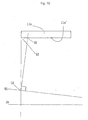
- FIG. 11 is a schematic diagram in the cross-sectional plane A1, showing only those lines and angles of FIG. 9 which are necessary for the calculation of the radial distance L001. Therefore, the reference symbols O and X-X, which actually denote a longitudinal axis and a horizontal plane, are used in FIG. 11 for indicating a point O and a line X-X, respectively.
- O and X-X which actually denote a longitudinal axis and a horizontal plane
- O-X is a horizontal line extending from line X-X and passing through the point O;
- O-Y is a line extending in the contact surface 11a' and passing through the point O;
- X1 is the point of intersection between the line O-Y and a line passing through the point G1 in perpendicular relation to the line O-Y;
- X2 is the point of intersection between the line O-X and a line passing through the point G1 in perpendicular relation to the line O-X;
- X3 is the point of intersection between the line G1 X2 and the line O-Y.
- the coordinates of the point G1 with reference to a given point on the axis O is computable.
- the distance between the points O and X2 is referred to as T1 and the distance between the points X2 and G1as T2, as shown by equations (1) and (2), respectively.
- two symbols separated by a middle dot (•) and having a bar at top in some equations denote a distance between two points represented by such symbols and that three symbols separated by similar middle dots signify an angle or a triangle formed by three points represented by such symbols.
- the distance X2•X3 is expressed by T1xtan ⁇ 001, as shown in equation (4).
- the distance X3•G1 is the difference between the distances X2•G1 and X2•X3, as shown in equation (5), and this may be expressed as T2-T1xtan ⁇ 0001, as shown in equation (6).
- the angle X3•G1•X1 is equal to the angle X3•O•X2 which is indicated by ⁇ 001, as shown in equations (7) and (8).
- the value for cos ⁇ 001 1 in the triangle G1•X1•X3 equals to the distance L001 divided by the distance X3•G1, as shown in equation (9).
- L001 can be expressed by equation (10). Substituting the distance X3•G1 by the right side of the equation (6), L001 can be further expressed by equation (11). As is be now apparent from the foregoing, the value for L00 1 can be found by substituting actual values for the distances T1, T2 and the angle ⁇ 001. The computed value for L001 is stored in memory of the control unit 20.
- the control unit 20 performs similar computations for the other radial distances L002, L003, L004, L005 and L006 according to the same procedure of calculation as described above. As mentioned earlier, the control unit 20 compares swung angles of any two adjacent contact surfaces and selects the angle of smaller value for storage in memory. Accordingly, the control unit 20 computes to determine the radial distance L002 from the point G2 to the contact surface 11 a' whose swung angle is smaller than that of its adjacent contact surface 11b' at the cross-sectional plane A2.
- the radial distances L003 from the point G3 to the contact surface 11b' whose swung angle is smaller than that of the contact surface 11c' at the plane A3 is computed for storage; the radial distances L004 from the point G4 to the contact surface 11d' whose swung angle is smaller than that of the contact surface 11c' at the plane A4 is computed for storage; and the radial distances L005 from the point G5 to the contact surface 11d' whose swung angle is smaller than that of the contact surface 11e' at the plane A5 is computed and stored, respectively.
- the radial distance L006 from the point G6 to the contact surface 11e' is computed.
- a radial distance to a specific contact surface refers not only to a distance directly to the contact surface, but also to a distance to an imaginary extension surface of that contact surface.
- FIG. 12 it shows an example of the positions of the contact surfaces 11a', 11b', 11c', 11d', 11e' when the log W is rotated by the spindles 3 for a predetermined angle (e.g. 10 degrees) from the position shown in FIG. 8 .
- points H1, H2, H3, H4, H5, H6 are the points of intersection between the optimum peeling axis HS and the respective cross-sectional planes A1, A2, A3.
- A4, A5, A6 are the points of intersection between the optimum peeling axis HS and the respective cross-sectional planes A1, A2, A3.
- A4, A5, A6 are the points of intersection between the optimum peeling axis HS and the respective cross-sectional planes A1, A2, A3.
- A4, A5, A6 are the points of intersection between the optimum peeling axis HS and the respective cross-sectional planes A1, A2, A3.
- A4, A5, A6 are the points of intersection between the optimum peeling axi
- the radial distance L011 from the point H1 to the contact surface 11a' at the plane A1 is computed and stored in memory.
- the radial distance L012 from the point H2 to the contact surface 11b' whose swung angle is smaller than that of the contact surface 11 a' at the plane A2 is computed and stored;
- the radial distances L013 from the point H3 to the contact surface 11 b' whose swung angle is smaller than that of the contact surface 11c' at the plane A3 is computed;
- the radial distances L014 from the point H4 to the contact surface 11d' whose swung angle is smaller than that of the contact surface 11c' at the plane A4 is computed;
- the radial distances L015 from the point H5 to the contact surface 11 e' whose swung angle is smaller than that of the contact surface 11d' at the sectional plane A5 is computed and stored in memory of the control unit 20, respectively.
- control unit 20 For determining the location of the maximum radius point of the log W with respect to the optimum peeling axis HS, the control unit 20 then compares the values in the memory thereof and determines the greatest value as representing the maximum radius point on the log's peripheral surface as measured from the optimum peeling axis HS.
- the knife carriage (not shown) of a rotary veneer lathe (not shown either) is moved relative to lathe spindles (not shown either) and set in the veneer lathe at such a position that the cutting edge of a veneer peeling knife (not shown either) mounted on the knife carriage is spaced from the longitudinal axial line of the lathe spindles at a distance that corresponds to the value of the distance for the maximum radius point of the log W.
- the above spaced distance may be slightly greater than the valve for the maximum radius point.
- the log W is released from the spindles 3 and transferred to and set in the veneer lathe between the lathe spindles in such a position that the calculated optimum peeling axis HS of the log W coincides with the aligned axes of the lathe spindles.
- the control unit 20 compares the swung angles of any two adjacent contact surfaces and selects the angle of a smaller value for storage in memory of the control unit 20.
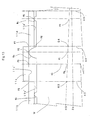
- FIG. 13 is a schematic diagram showing a part of a log W and three contact plates 11b, 11c, 11d with the contact surfaces 11b', 11c', 11d'.
- the surface irregularities of the log W are represented by the presence of three exaggerated projections Wa, Wb and Wc. As seen in FIG. 13 , these projections Wa, Wb and Wc are in contact with the contact surfaces 11c', 11b' and 11d', respectively.
- P2 is a point of contact between the projection Wa and the contact surface 11c';
- P1 is a point of intersection between the optimum peeling axis HS and a vertical plane extending in parallel, e.g. to the cross-sectional plane A4 and passing through the point P2;
- P3 is a point of intersection between the contact surface 11c' and a line passing through the point G3 and in perpendicular relation to the contact surface 11c';
- P5 is a point of contact between the projection Wc and the contact surface 11d';
- P4 is a point of intersection between the optimum peeling axis HS and a vertical plane extending in parallel, e.g.
- P6 is a point of intersection between the contact surface 11d' and a line passing through the point G4 and in perpendicular relation to the contact surface 11d'
- P7 is a point of intersection between the contact surface 11c' and a line passing through the point G4 and in perpendicular relation to the contact surface 11c'.
- the contact surface 11c' is located furthest from the preliminary axis 3b of the log W in the drawing because of the presence of the projection Wa on the log W.
- the projection Wa is in contact with the contact surface 11c' at a location that is close to the right side of the contact plate 11c and also that the computed optimum peeling axis HS extends declining rightward as shown in 12.
- the swung angle of each contact surface is taken at a position of the log W corresponding to the left side thereof, i.e. at the cross-sectional plane A3 for the contact surface 11c' and at the cross-sectional plane A4 for the contact surface 11d', a problem occurs as follow.
- the distance from the optimum peeling axis HS to the contact surfaces 11c', or the distance between the points G3 and P3 at the plane A3 as calculated according to the procedure described with reference to FIG. 11 will be regarded as having the maximum value for the section of the log W that corresponds to the contact surface 11 c' in spite that this distance is smaller than the distance between the points P1 and P2, as clearly seen from FIG. 13 .
- the distance between the points G3 and P3 is regarded as the point for the maximum radius of the log W and the knife carriage is set with the cutting edge of the veneer peeling knife spaced from the axial line of the lathe spindles based on such information, the projection Wa will collide against the knife on the knife carriage when the log W is rotated, thereby inviting a breakage not only to the knife but also to any other part of the veneer lathe.
- the space between the computed optimum peeling axis HS and any contact surface e.g.
- the contact surface 11c' is widened away from the location (or the plane A3 in the case of the contact surface 11c') which was selected as the location for calculation of the distance based on the swung angle of the contact surface as in the case shown in FIG. 13 , the computed distance between the optimum peeling axis HS and contact surface is smaller than the spaced distance from the same axis HS to point P2 of the projection Wa. If the maximum radius point is thus determined, harmful collision of the log W with the knife may occur during the first rotation of the log W.
- the control unit 20 is operable to compare angles swung by any two adjacent contact surfaces and selects the angle of a smaller value for calculation of a distance between the computed optimum peeling axis and the contact surface.
- the swung angle of the contact surface 11c' that is smaller than that of its adjacent contact surface 11 b' is selected for calculation of the distance between the optimum peeling axis and the contact surface.
- the swung angle of the contact surface 11c' that is smaller than that of its adjacent contact surface 11d' is selected for the same purpose.
- distances between the points G3 and P3 and the points G4 and P7 are computed on the basis the swung angle of the contact surface 1 1c' for comparison and the larger distance between the points G4 and P7 is selected as the distance representing the maximum radius point on the log peripheral surface.
- the distance between the points G4 and P7 is larger than the distance between the points P 1 and P2 that represents the actual maximum radius point of the log W and, therefore, the veneer knife on the carriage will be set slightly further than the optimum position, with the result that a longer time is spent before veneer peeling begins. However, such extension of time is negligible.
- the control unit 20 has operated to figure out the angle ⁇ swung by the contact surface, i.e. the angle ⁇ then made between the horizontal plane X-X and the plane of the contact surfaces, on the basis of information of the angular position provided by the rotary encoders.
- the dimension of a radial distance e.g. L001
- L001 the angle of a contact surface relative to the arbitrary standby position X-X
- the angle of that contact surface relative to the reference position that is defined by an imaginary plane passing through the fixed axes 3b and O.
- control unit 20 may be operable to figure out an angle made between the contact surface and the reference position on the basis of information of angular position of the contact surface and also to compare such angles of any two adjacent contact surfaces.
- the angle between the contact surface and the reference position can be found easily merely by subtracting the angle ⁇ from the known angle made between the reference position and the horizontal plane X-X.
- Imaginary cross-sectional planes of a log W may be set at the center of width of the respective contact surfaces, as indicated by an imaginary cross-sectional plane D3 for the third contact surface 11c' shown in FIG. 13 .
- P8 designates the point of intersection between the imaginary cross-sectional plane D3 and the optimum peeling axis HS
- point P9 denotes the point of intersection between the contact surface 11c' and an imaginary line extending through the point P8 and perpendicularly to the contact surface 11c'.
- Distance between the points P8 and P9 can be found by substituting the swung angle of the contact surface 11c' for ⁇ 00 1 in equation (11) of FIG. 11 .
- the point P8 is different from the points G3 and G4 on the optimum peeling axis HS which is computed in three-dimensional coordinates and, therefore, actual values for T1 and T2 need be figured out for substitution in equation (11).
- the distance between the points P8 and P9 is shorter than the distance between the points P 1 and P2
- error in the maximum radius point of the log is advantageously smaller than in the case where the distance between the points G3 and P3 is selected for the maximum radius point.
- the knife carriage may be set relative to the lathe spindles such that the cutting edge of veneer peeling knife is spaced from the longitudinal axial line of the lathe spindles at a distance that is slightly greater than the valve for the computed maximum radius point.
- the calculation procedure may be simplified as follows. At each of the equiangularly spaced positions of the log W, angles swung by the respective contact surfaces 10a, 10b, 10c, 10d, 10e are compared and the smallest angle is selected. Then, on the basis of such selected angles, distances from the optimum peeling axis HS to the respective contact surfaces along a line extending perpendicularly to the contact surface are computed. Of all such computed distances, the largest distance is taken as the distance for the maximum radius of the log. This simplified calculation helps to shorten the time for the calculation.
- contact surfaces 11a', 11b', 11c', 11d', 11e' in the preferred embodiment have substantially the same width extending along the axis O of the support shaft 13 as shown, e.g. in FIG. 3 , it may be so arranged that two contact surfaces 11a' and 11e' located on the opposite sides are smaller in width than the other contact surfaces 11b', 11c' and 11d'.
- the contact surfaces 11a', 11b', 11c', 11d', 11e' are swung into contact with the peripheral surface of the log W after it has been held by the spindles 3.
- the contact surfaces may be moved into contact with the log periphery before it is held by the spindles or substantially simultaneously with the holding by the spindles.
- the laser devices 9a, 9b, 9c and the rotary encoders 19a, 19b, 19c, 19d, 19e are operable to make measurements simultaneously for the distances and the angles, respectively, at each of the equiangularly spaced positions of the spindle 3 or the log W, the laser devices and the rotary encoders may be operated independently at different angularly spaced positions of the log W.
Landscapes
- Engineering & Computer Science (AREA)
- Life Sciences & Earth Sciences (AREA)
- Manufacturing & Machinery (AREA)
- Wood Science & Technology (AREA)
- Forests & Forestry (AREA)
- Length Measuring Devices By Optical Means (AREA)
- Finish Polishing, Edge Sharpening, And Grinding By Specific Grinding Devices (AREA)
- Mechanical Treatment Of Semiconductor (AREA)
- Processing Of Stones Or Stones Resemblance Materials (AREA)
- Manufacture Of Motors, Generators (AREA)
Claims (18)
- Ein Verfahren zum Bestimmen einer optimalen Schälachse (HS) eines Baumstamms (W) und eines Punkts mit Maximalradius an der Außenfläche des Baumstamms mit Bezug auf die genannte optimale Schälachse basierend auf Information über das Außenprofil des Baumstamms, der zumindest um eine ganze Umdrehung um dessen vorläufige Achse (3b) rotiert wird, bestehend aus:Berechnen einer optimalen Schälachse des Baumstamms auf der Basis radialer Abstände des Baumstamms von der genannten vorläufigen Achse zur Außenfläche des Baumstamms an mehreren vorbestimmten Punkten, die entlang der genannten vorläufigen Achse des Baumstamms jeweils an einer Reihe vorbestimmter, winklig beabstandeter Punkte am Baumstamm verteilt sind;Bereitstellung mehrerer schwenkbarer Glieder (10), die schwenkbar an einer Welle montiert sind, die eine Längsachse aufweist, die parallel zur genannten vorläufigen Achse des Baumstamms verläuft, und die flache Kontaktflächen (11a'), deren Breite jeweils entlang der genannten Längsachse (0) verläuft, haben, wobei jede der genannten Kontaktflächen mit dem schwenkbaren Glied (10) relativ zu einer Bezugsposition schwenkbar ist, die durch eine imaginäre Ebene definiert wird, die durch die genannten vorläufige Achse verläuft, und die genannte Längsachse, während sie mit der Außenfläche des Baumstamms in Kontakt ist, somit dem Außenprofil des Baumstamms, der um die genannten vorläufige Achse rotiert wird, folgt;Messen der Winkelposition der Kontaktfläche jedes schwenkbaren Glieds hinsichtlich der genannten Bezugsposition an jedem der genannten vorbestimmten, winklig beabstandeten Punkte am Baumstamm durch das genannte schwenkbare Glied;Bestimmen des genannten Punkts des Maximalradius des Baumstamms:dadurch gekennzeichnet, dass das genannte Bestimmen des Punkts mit Maximalradius des Baumstamms durch Berechnen der Radialabstände des Baumstamms von mehreren vorbestimmten Positionen an der genannten optimalen Schälachse zu ausgewählten Kontaktflächen basierend auf den gemessenen Winkelpositionen der Kontaktflächen entlang imaginärer Linien, die senkrecht zur genannten vorläufigen Achse verlaufen, erfolgt, sowie Vergleich der genannten berechneten Radialabstände, um den Abstand mit dem größten Wert als Punkt mit Maximalradius des Baustamms zu erkennen.
- Ein Verfahren gemäß Anspruch 1, wobei die genannten vorbestimmten Positionen auf der berechneten optimalen Schälachse Schnittpunkte zwischen der genannten optimalen Schälachse (HS) und entsprechenden imaginären Ebenen (A1-A6) sind, die sich über den Baumstamm auf einer Seite der Breite der Kontaktflächen (11a'-11e') in senkrechter Beziehung zur genannten vorläufigen Achse des Baumstamms erstrecken.
- Ein Verfahren gemäß Anspruch 2, das zudem aus dem Vergleich von Winkeln von jeweils zwei benachbarten Kontaktflächen hinsichtlich der genannten Bezugsposition auf der Basis der Winkelpositionen von zwei solchen benachbarten Kontaktflächen besteht, die jeweils an den genannten vorbestimmten, winklig beabstandeten Punkten des Baumstamms gemessen werden, wobei die genannten gewählten Kontaktflächen eine der genannten beiden benachbarten Kontaktflächen mit einbeziehen, deren Winkel hinsichtlich des genannten Bezugspunkts größer als derjenige der anderen der beiden benachbarten Kontaktflächen ist.
- Ein Verfahren gemäß Anspruch 1, wobei die genannten vorbestimmten Positionen auf der berechneten optimalen Schälachse (HS) Schnittpunkte zwischen der genannten optimalen Schälachse und entsprechenden imaginären Ebenen sind, die sich über den Baumstamm an einem wesentlichen Mittelpunkt der Breite der Kontaktflächen (11a'-11e') in senkrechter Beziehung zur genannten vorläufigen Achse des Baumstamms erstrecken, und wobei die genannten gewählten Kontaktflächen alle Kontaktflächen einbeziehen.
- Ein Verfahren zum Bestimmen einer optimalen Schälachse (HS) eines Baumstamms (W) und eines Punkts mit Maximalradius an der Außenfläche des Baumstamms mit Bezug auf die genannte optimale Schälachse basierend auf Information über das Außenprofil des Baumstamms, der zumindest um eine ganze Umdrehung um dessen vorläufige Achse (3b) rotiert wird, bestehend aus: Berechnen einer optimalen Schälachse des Baumstamms auf der Basis radialer Abstände des Baumstamms von der genannten vorläufigen Achse zur Außenfläche des Baumstamms an mehreren vorbestimmten Punkten, die entlang der genannten vorläufigen Achse des Baumstamms an jeder einer Reihe vorbestimmter, winklig beabstandeter Punkte am Baumstamm verteilt sind; Bereitstellung mehrerer schwenkbarer Glieder (10), die schwenkbar an einer Welle montiert sind, die eine Längsachse (0) aufweist, die parallel zur genannten vorläufigen Achse des Baumstamms verläuft, und die flache Kontaktflächen (11a'-11e'), deren Breite jeweils entlang der genannten Längsachse (0) verläuft, haben, wobei jede der genannten Kontaktflächen mit dem schwenkbaren Glied relativ zu einer Bezugsposition schwenkbar ist, die durch eine imaginäre Ebene definiert wird, die durch die genannten vorläufige Achse verläuft, und die genannte Längsachse, während sie mit der Außenfläche des Baumstamms in Kontakt ist, somit dem Außenprofil des Baumstamms, der um die genannte vorläufige Achse rotiert wird, folgt;
Messen von Winkelposition der Kontaktfläche jedes schwenkbaren Glieds hinsichtlich der genannten Bezugsposition an jedem der genannten vorbestimmten, winklig beabstandeten Punkte am Baumstamm durch das genannte schwenkbare Glied; Bestimmen des genannten Punkts des Maximalradius des Baumstamms:dadurch gekennzeichnet, dass das genannte Bestimmen des Punkts mit Maximalradius des Baumstamms, das Berechnen der Radialabstände des Baumstamms von mehreren vorbestimmten Positionen an der genannten optimalen Schälachse zu ausgewählten Kontaktflächen durch Berechnen von Radialabständen des Baumstamms von mehreren vorbestimmten Positionen auf der genannten berechneten optimalen Schälachse von ausgewählten Kontaktflächen basierend auf den gemessenen Winkelpositionen der Kontaktflächen entlang imaginärer Linien erfolgt, die senkrecht zur genannten optimalen Schälachse verlaufen, sowie Vergleich der genannten berechneten Radialabstände, um den Abstand mit dem größten Wert als Punkt mit Maximalradius des Baustamms zu erkennen. - Ein Verfahren gemäß Anspruch 5, wobei die genannten vorbestimmten Positionen auf der berechneten optimalen Schälachse (HS) Schnittpunkte zwischen der genannten optimalen Schälachse und entsprechenden imaginären Ebenen (A1-A6) sind, die sich über den Baumstamm auf einer Seite der Breite der Kontaktflächen in senkrechter Beziehung zur genannten vorläufigen Achse des Baumstamms erstrecken.
- Ein Verfahren gemäß Anspruch 6, das zudem aus dem Vergleich von Winkeln von jeweils zwei benachbarten Kontaktflächen hinsichtlich der genannten Bezugsposition auf der Basis der Winkelpositionen von zwei solchen benachbarten Kontaktflächen besteht, die jeweils an den genannten vorbestimmten, winklig beabstandeten Punkten des Baumstamms gemessen werden, wobei die genannten gewählten Kontaktflächen eine der genannten beiden benachbarten Kontaktflächen mit einbeziehen, deren Winkel hinsichtlich des genannten Bezugspunkts größer als derjenige der anderen der beiden benachbarten Kontaktflächen ist.
- Ein Verfahren gemäß Anspruch 5, wobei die genannten vorbestimmten Positionen auf der berechneten optimalen Schälachse (HS) Schnittpunkte zwischen der genannten optimalen Schälachse und entsprechenden imaginären Ebenen sind, die sich über den Baumstamm an einem wesentlichen Mittelpunkt der Breite der Kontaktflächen (11a'-11e') in senkrechter Beziehung zur genannten vorläufigen Achse des Baumstamms erstrecken.
- Ein Gerät zum Bestimmen einer optimalen Schälachse eines Baumstamms (W) und eines Punkts mit Maximalradius an der Außenfläche des Baumstamms mit Bezug auf die genannte optimale Schälachse (HS) bestehend aus: einem Spindelpaar (3), in denen ein Baumstamm an dessen vorläufiger Achse (3b) gehalten wird;
einem Antrieb zum Antreiben von mindestens einem Paar der genannten gepaarten Spindeln, wodurch der Baumstamm um mindestens eine ganze Umdrehung um die genannte vorläufige Achse rotiert wird;
einem ersten Sensor zur Feststellung mehrerer winklig beabstandeter Punkte von mindestens einer der genannten Spindeln und somit des Baumstamms; mehreren schwenkbaren Gliedern (10), die schwenkbar an einer Welle (13) montiert sind, die eine Längsachse (0) aufweist, die parallel zur genannten vorläufigen Achse des Baumstamms verläuft, und die flache Kontaktflächen (11a'-11e'), deren Breite jeweils entlang der genannten Längsachse (0) verläuft, haben, wobei jede der genannten Kontaktflächen mit dem schwenkbaren Glied relativ zu einer Bezugsposition schwenkbar ist, die durch eine imaginäre Ebene definiert wird, die durch die genannten vorläufige Achse verläuft, und die genannte Längsachse, während sie mit der Außenfläche des Baumstamms in Kontakt ist, somit dem Außenprofil des Baumstamms, der um die genannte vorläufige Achse rotiert wird, folgt;
einer Reihe von zweiten Sensoren (9), die in Abständen entlang der genannten vorläufigen Achse des Baumstamms verteilt sind, um die Abstände von den jeweiligen zweiten Sensoren zur Außenfläche des Baumstamms an jedem der genannten, im winklig beabstandeten Punkte des Baumstamms zu messen;
einer Reihe dritter Sensoren, die in Verbindung mit den genannten schwenkbaren Gliedern operiert werden können, um Winkelpositionen der Kontaktflächen hinsichtlich der genannten Bezugsposition an jedem der genannten, winklig beabstandeten Punkte des Baumstamms zu messen; und eine Steuereinrichtung, die so operiert werden kann, dass sie die optimale Schälachse des Baumstamms auf der Basis der genannten, von den zweiten Sensoren gemessenen Abstände berechnen kann;
dadurch gekennzeichnet, dass die genannte Steuereinrichtung so operiert werden kann, dass sie Radialabstände des Baumstamms von mehreren vorbestimmten Positionen an der genannten berechneten optimalen Schälachse zu gewählten Kontaktflächen auf der Basis der gemessenen Winkelpositionen der Kontaktflächen entlang imaginärer Linien berechnen kann, die sich senkrecht zur genannten vorläufigen Achse des Baumstamms erstrecken, und die genannten berechneten Radialabstände vergleicht, um den Abstand mit dem größten Wert als Punkt mit Maximalradius des Baumstamms zu erkennen. - Ein Gerät gemäß Anspruch 9, wobei die vorbestimmten Positionen auf der berechneten optimalen Schälachse (HS) Schnittpunkte zwischen der genannten optimalen Schälachse und entsprechenden imaginären Ebenen (A1-A6) sind, die sich über den Baumstamm an einer Seite der Breite der Kontaktflächen in senkrechter Beziehung zur genannten vorläufigen Achse des Baumstamms erstrecken.
- Ein Gerät gemäß Anspruch 10, wobei die genannte Steuereinrichtung so operiert werden kann, dass sie Winkel von jeweils zwei benachbarten Kontaktflächen hinsichtlich der genannten Bezugsposition auf der Basis der Winkelpositionen von zwei solchen benachbarten Kontaktflächen vergleicht, die jeweils an den genannten vorbestimmten, winklig beabstandeten Punkten des Baumstamms gemessen werden, wobei die genannten gewählten Kontaktflächen eine der genannten beiden benachbarten Kontaktflächen mit einbeziehen, deren Winkel hinsichtlich des genannten Bezugspunkts größer als derjenige der anderen der beiden benachbarten Kontaktflächen ist.
- Ein Gerät gemäß Anspruch 9, wobei die genannten vorbestimmten Positionen auf der berechneten optimalen Schälachse Schnittpunkte zwischen der genannten optimalen Schälachse (HS) und entsprechenden imaginären Ebenen sind, die sich über den Baumstamm an einem wesentlichen Mittelpunkt der Breite der Kontaktflächen (11a'-11e') in senkrechter Beziehung zur genannten vorläufigen Achse des Baumstamms erstrecken, und wobei die genannten gewählten Kontaktflächen alle Kontaktflächen einbeziehen.
- Ein Gerät gemäß Anspruch 9, wobei zum genannten dritten Sensor (19) ein Drehgeber gehört.
- Ein Gerät zum Bestimmen einer optimalen Schälachse (HS) eines Baumstamms (W) und eines Punkts mit Maximalradius an der Außenfläche des Baumstamms mit Bezug auf die genannte optimale Schälachse bestehend aus: einem Spindelpaar, in denen ein Baumstamm an dessen vorläufiger Achse (3b) gehalten wird;
einem Antrieb zum Antreiben von mindestens einem Paar der genannten gepaarten Spindeln, wodurch der Baumstamm um mindestens eine ganze Umdrehung um die genannte vorläufige Achse rotiert wird;
einem ersten Sensor zur Feststellung mehrerer winklig beabstandeter Punkte von mindestens einer der genannten Spindeln und somit des Baumstamms; mehreren schwenkbaren Gliedern (10), die schwenkbar an einer Welle montiert sind, die eine Längsachse (0) aufweist, die parallel zur genannten vorläufigen Achse des Baumstamms verläuft, und die flache Kontaktflächen (11a'-11e'), deren Breite jeweils entlang der genannten Längsachse (0) verläuft, haben, wobei jede der genannten Kontaktflächen mit dem schwenkbaren Glied relativ zu einer Bezugsposition schwenkbar ist, die durch eine imaginäre Ebene definiert wird, die durch die genannten vorläufige Achse verläuft, und die genannte Längsachse, während sie mit der Außenfläche des Baumstamms in Kontakt ist, somit dem Außenprofil des Baumstamms, der um die genannte vorläufige Achse rotiert wird, folgt;
einer Reihe von zweiten Sensoren (9), die in Abständen entlang der genannten vorläufigen Achse des Baumstamms verteilt sind, um die Abstände von den jeweiligen zweiten Sensoren zur Außenfläche des Baumstamms an jedem der genannten, winklig beabstandeten Punkten des Baumstamms zu messen; einer Reihe dritter Sensoren, die in Verbindung mit den genannten schwenkbaren Gliedern operiert werden können, um Winkelpositionen der Kontaktflächen hinsichtlich der genannten Bezugsposition an jedem der genannten, winklig beabstandeten Punkte des Baumstamms zu messen; und eine Steuereinrichtung, die so operiert werden kann, dass sie die optimale Schälachse des Baumstamms auf der Basis der genannten, von den zweiten Sensoren gemessenen Abständen berechnen kann;
dadurch gekennzeichnet, dass die genannte Steuereinrichtung so operiert werden kann, dass sie Radialabstände des Baumstamms von mehreren vorbestimmten Positionen an der genannten berechneten optimalen Schälachse zu gewählten Kontaktflächen auf der Basis der gemessenen Winkelpositionen der Kontaktflächen entlang imaginärer Linien berechnen kann, die sich senkrecht zur genannten vorläufigen Achse des Baumstamms erstrecken, und die genannten berechneten Radialabstände vergleicht, um den Abstand mit dem größten Wert als Punkt mit Maximalradius des Baumstamms zu erkennen. - Ein Gerät gemäß Anspruch 14, wobei die vorbestimmten Positionen auf der berechneten optimalen Schälachse (HS) Schnittpunkte zwischen der genannten optimalen Schälachse und entsprechenden imaginären Ebenen (A1-A6) sind, die sich über den Baumstamm an einer Seite der Breite der Kontaktflächen in senkrechter Beziehung zur genannten vorläufigen Achse des Baumstamms erstrecken.
- Ein Gerät gemäß Anspruch 15, wobei die genannte Steuereinrichtung so operiert werden kann, dass sie Winkel von jeweils zwei benachbarten Kontaktflächen hinsichtlich der genannten Bezugsposition auf der Basis der Winkelpositionen von zwei solchen benachbarten Kontaktflächen vergleicht, die jeweils an den genannten vorbestimmten, winklig beabstandeten Punkten des Baumstamms gemessen werden, wobei die genannten gewählten Kontaktflächen eine der genannten beiden benachbarten Kontaktflächen mit einbeziehen, deren Winkel hinsichtlich des genannten Bezugspunkts größer als derjenige der anderen der beiden benachbarten Kontaktflächen ist.
- Ein Gerät gemäß Anspruch 14, wobei die genannten vorbestimmten Positionen auf der berechneten optimalen Schälachse Schnittpunkte zwischen der genannten optimalen Schälachse (HS) und entsprechenden imaginären Ebenen sind, die sich über den Baumstamm an einem wesentlichen Mittelpunkt der Breite der Kontaktflächen (11a'-11e') in senkrechter Beziehung zur genannten vorläufigen Achse des Baumstamms erstrecken, und wobei die genannten gewählten Kontaktflächen alle Kontaktflächen einbeziehen.
- Ein Gerät gemäß Anspruch 14, wobei zum genannten dritten Sensor (19) ein Drehgeber gehört.
Priority Applications (5)
| Application Number | Priority Date | Filing Date | Title |
|---|---|---|---|
| CA002538050A CA2538050C (en) | 2006-02-28 | 2006-02-28 | Method and apparatus of locating the optimum peeling axis of a log and the maximum radius portion thereof with respect to the optimum peeling axis |
| EP06110523A EP1825976B1 (de) | 2006-02-28 | 2006-02-28 | Verfahren und Vorrichtung zum Bestimmen der optimalen Schälachse eines Baumstammes sowie dessen Punkt mit Maximalradius mit Bezug auf die Schälachse |
| DE602006015767T DE602006015767D1 (de) | 2006-02-28 | 2006-02-28 | Verfahren und Vorrichtung zum Bestimmen der optimalen Schälachse eines Baumstammes sowie dessen Punkt mit Maximalradius mit Bezug auf die Schälachse |
| AU2006200898A AU2006200898B2 (en) | 2006-02-28 | 2006-03-02 | Method and apparatus of locating the optimum peeling axis of a log and the maximum radius portion thereof with respect to the optimum peeling axis |
| US11/372,100 US7275571B1 (en) | 2006-02-28 | 2006-03-10 | Method and apparatus of locating the optimum peeling axis of a log and the maximum radius portion thereof with respect to the optimum peeling axis |
Applications Claiming Priority (4)
| Application Number | Priority Date | Filing Date | Title |
|---|---|---|---|
| CA002538050A CA2538050C (en) | 2006-02-28 | 2006-02-28 | Method and apparatus of locating the optimum peeling axis of a log and the maximum radius portion thereof with respect to the optimum peeling axis |
| EP06110523A EP1825976B1 (de) | 2006-02-28 | 2006-02-28 | Verfahren und Vorrichtung zum Bestimmen der optimalen Schälachse eines Baumstammes sowie dessen Punkt mit Maximalradius mit Bezug auf die Schälachse |
| AU2006200898A AU2006200898B2 (en) | 2006-02-28 | 2006-03-02 | Method and apparatus of locating the optimum peeling axis of a log and the maximum radius portion thereof with respect to the optimum peeling axis |
| US11/372,100 US7275571B1 (en) | 2006-02-28 | 2006-03-10 | Method and apparatus of locating the optimum peeling axis of a log and the maximum radius portion thereof with respect to the optimum peeling axis |
Publications (2)
| Publication Number | Publication Date |
|---|---|
| EP1825976A1 EP1825976A1 (de) | 2007-08-29 |
| EP1825976B1 true EP1825976B1 (de) | 2010-07-28 |
Family
ID=42733789
Family Applications (1)
| Application Number | Title | Priority Date | Filing Date |
|---|---|---|---|
| EP06110523A Expired - Lifetime EP1825976B1 (de) | 2006-02-28 | 2006-02-28 | Verfahren und Vorrichtung zum Bestimmen der optimalen Schälachse eines Baumstammes sowie dessen Punkt mit Maximalradius mit Bezug auf die Schälachse |
Country Status (5)
| Country | Link |
|---|---|
| US (1) | US7275571B1 (de) |
| EP (1) | EP1825976B1 (de) |
| AU (1) | AU2006200898B2 (de) |
| CA (1) | CA2538050C (de) |
| DE (1) | DE602006015767D1 (de) |
Families Citing this family (2)
| Publication number | Priority date | Publication date | Assignee | Title |
|---|---|---|---|---|
| JP5591466B2 (ja) * | 2008-11-06 | 2014-09-17 | 株式会社名南製作所 | 原木の3次元形状測定装置および方法 |
| CA3132148C (en) | 2019-08-01 | 2025-06-10 | Meinan Machinery Works, Inc. | KNIFE HOLDER, ROTARY DISPENSER EQUIPPED WITH THIS KNIFE, AND SLICER EQUIPPED WITH THIS KNIFE |
Family Cites Families (9)
| Publication number | Priority date | Publication date | Assignee | Title |
|---|---|---|---|---|
| GB1374650A (en) * | 1971-07-13 | 1974-11-20 | Taihei Seisakusho Kk | Method and apparatus for preshaping raw logs |
| US4246940A (en) * | 1978-07-17 | 1981-01-27 | Applied Theory Associates, Inc. | Veneer lathe charging apparatus and method for determining log spin axis |
| US4965734A (en) * | 1977-02-25 | 1990-10-23 | Applied Theory, Division Of U.S.N.R., Inc. | Veneer lathe charging method for determining log spin axis |
| US4397343A (en) * | 1981-08-31 | 1983-08-09 | The Coe Manufacturing Co. | Log scanning in veneer lathe to determine optimum yield axis |
| US4977805A (en) * | 1986-04-10 | 1990-12-18 | Corley Manufacturing Company | Edging apparatus |
| JP3569304B2 (ja) | 1992-12-22 | 2004-09-22 | 株式会社太平製作所 | 原木の芯出し方法、芯出し供給方法およびそれらの装置 |
| JP3676546B2 (ja) * | 1997-08-21 | 2005-07-27 | 株式会社名南製作所 | レースチャージャ |
| FI107320B (fi) * | 1999-07-20 | 2001-07-13 | Raute Oyj | Menetelmä pyöristyssorvauksen aloituskohdan määrittämiseksi vaneria sorvattaessa |
| TWI235101B (en) * | 2003-04-25 | 2005-07-01 | Meinan Machinery Works | Method and apparatus for centering a log |
-
2006
- 2006-02-28 EP EP06110523A patent/EP1825976B1/de not_active Expired - Lifetime
- 2006-02-28 CA CA002538050A patent/CA2538050C/en not_active Expired - Lifetime
- 2006-02-28 DE DE602006015767T patent/DE602006015767D1/de not_active Expired - Lifetime
- 2006-03-02 AU AU2006200898A patent/AU2006200898B2/en not_active Expired
- 2006-03-10 US US11/372,100 patent/US7275571B1/en active Active
Also Published As
| Publication number | Publication date |
|---|---|
| US7275571B1 (en) | 2007-10-02 |
| AU2006200898A1 (en) | 2007-09-20 |
| US20070209735A1 (en) | 2007-09-13 |
| AU2006200898B2 (en) | 2011-05-26 |
| EP1825976A1 (de) | 2007-08-29 |
| CA2538050C (en) | 2009-07-21 |
| DE602006015767D1 (de) | 2010-09-09 |
| CA2538050A1 (en) | 2007-08-28 |
Similar Documents
| Publication | Publication Date | Title |
|---|---|---|
| EP2340138B1 (de) | Einspannvorrichtung und verfahren zum zentrieren eines gegenstands in einem spannfutter | |
| JP6479880B2 (ja) | チューブが反射または放出した放射を測定するためのセンサを用いて、レーザ切断機械上で加工されるチューブを走査する方法 | |
| JP7365934B2 (ja) | 歯切り盤の測定プローブを較正する方法 | |
| JP3453568B2 (ja) | ワーク位置決め手段を具えた数値制御装置内蔵フライス盤 | |
| KR20170074817A (ko) | 화상 정보와 레이저 센서를 이용한 배관 정렬 상태 검출 장치 및 방법 | |
| JPWO2008062609A1 (ja) | タイヤの測定方法、同測定装置及びタイヤ成形装置 | |
| KR20170045689A (ko) | 금속봉의 직진도 자동 교정 장비 및 금속봉의 직진도 자동 교정 방법 | |
| EP1825976B1 (de) | Verfahren und Vorrichtung zum Bestimmen der optimalen Schälachse eines Baumstammes sowie dessen Punkt mit Maximalradius mit Bezug auf die Schälachse | |
| EP1470903B1 (de) | Vorrichtung zum Zentrieren eines Baumstamms | |
| JP6717287B2 (ja) | 溶接管の溶接部の形状寸法測定装置 | |
| CA2777207A1 (en) | Surface measurement, selection, and machining | |
| RU2321488C2 (ru) | Способ и устройство для определения местоположения оптимальной оси лущения кряжа и точки его максимального радиуса на поверхности кряжа относительно оптимальной оси лущения | |
| JPH0639683A (ja) | 旋削加工機の加工テーブルへの被加工物の芯出し方 法及びその装置 | |
| NZ545665A (en) | Method and apparatus of locating the optimum peeling axis of a log and the maximum radius portion thereof with respect to the optimum peeling axis | |
| CN101015919B (zh) | 原木旋削轴芯及最大转动半径的检测方法及装置 | |
| JP7345077B1 (ja) | 加工機 | |
| JP2012066555A (ja) | 木材加工装置 | |
| EP3865267B1 (de) | Kantenbeschichtungsvorrichtung für holzteile mit messgerät für die holzteilposition am eingang der vorrichtung und zugehöriges verfahren zu desssen durchführung | |
| WO2007063527A2 (en) | Multifunctional tool machine for correction of planarity errors and reducing tensioning in disk-shaped blades, as well as method and program for controlling such machine | |
| JP4772430B2 (ja) | 原木旋削軸芯及び最大回転半径の検出方法及び装置 | |
| KR101183102B1 (ko) | 원목의 선삭 축심 및 최대 회전반경의 검출방법 및 장치 | |
| JPH01289525A (ja) | 板材折曲げ加工装置 | |
| JPS6133446B2 (de) | ||
| JPH08215930A (ja) | 切断機における位置決め制御方法およびその装置 |
Legal Events
| Date | Code | Title | Description |
|---|---|---|---|
| PUAI | Public reference made under article 153(3) epc to a published international application that has entered the european phase |
Free format text: ORIGINAL CODE: 0009012 |
|
| AK | Designated contracting states |
Kind code of ref document: A1 Designated state(s): AT BE BG CH CY CZ DE DK EE ES FI FR GB GR HU IE IS IT LI LT LU LV MC NL PL PT RO SE SI SK TR |
|
| AX | Request for extension of the european patent |
Extension state: AL BA HR MK YU |
|
| 17P | Request for examination filed |
Effective date: 20080218 |
|
| AKX | Designation fees paid |
Designated state(s): DE FI IT |
|
| 17Q | First examination report despatched |
Effective date: 20081008 |
|
| GRAP | Despatch of communication of intention to grant a patent |
Free format text: ORIGINAL CODE: EPIDOSNIGR1 |
|
| RTI1 | Title (correction) |
Free format text: METHOD AND APPARATUS FOR LOCATING THE OPTIMUM PEELING AXIS OF A LOG AND THE MAXIMUM RADIUS POINT THEREOF WITH RESPECT TO THE OPTIMUM PEELING AXIS |
|
| GRAS | Grant fee paid |
Free format text: ORIGINAL CODE: EPIDOSNIGR3 |
|
| GRAA | (expected) grant |
Free format text: ORIGINAL CODE: 0009210 |
|
| AK | Designated contracting states |
Kind code of ref document: B1 Designated state(s): DE FI IT |
|
| REF | Corresponds to: |
Ref document number: 602006015767 Country of ref document: DE Date of ref document: 20100909 Kind code of ref document: P |
|
| PLBE | No opposition filed within time limit |
Free format text: ORIGINAL CODE: 0009261 |
|
| STAA | Information on the status of an ep patent application or granted ep patent |
Free format text: STATUS: NO OPPOSITION FILED WITHIN TIME LIMIT |
|
| 26N | No opposition filed |
Effective date: 20110429 |
|
| REG | Reference to a national code |
Ref country code: DE Ref legal event code: R097 Ref document number: 602006015767 Country of ref document: DE Effective date: 20110429 |
|
| REG | Reference to a national code |
Ref country code: DE Ref legal event code: R119 Ref document number: 602006015767 Country of ref document: DE Effective date: 20110901 |
|
| PG25 | Lapsed in a contracting state [announced via postgrant information from national office to epo] |
Ref country code: DE Free format text: LAPSE BECAUSE OF NON-PAYMENT OF DUE FEES Effective date: 20110901 |
|
| PGFP | Annual fee paid to national office [announced via postgrant information from national office to epo] |
Ref country code: IT Payment date: 20190221 Year of fee payment: 14 |
|
| PG25 | Lapsed in a contracting state [announced via postgrant information from national office to epo] |
Ref country code: IT Free format text: LAPSE BECAUSE OF NON-PAYMENT OF DUE FEES Effective date: 20200228 |
|
| P01 | Opt-out of the competence of the unified patent court (upc) registered |
Effective date: 20230516 |
|
| PGFP | Annual fee paid to national office [announced via postgrant information from national office to epo] |
Ref country code: FI Payment date: 20250218 Year of fee payment: 20 |