EP1820871A1 - Verfahren und Vorrichtung zum Ausscheidungshärten von hochlegierten Leichtmetallen mittels Induktion - Google Patents
Verfahren und Vorrichtung zum Ausscheidungshärten von hochlegierten Leichtmetallen mittels Induktion Download PDFInfo
- Publication number
- EP1820871A1 EP1820871A1 EP07000735A EP07000735A EP1820871A1 EP 1820871 A1 EP1820871 A1 EP 1820871A1 EP 07000735 A EP07000735 A EP 07000735A EP 07000735 A EP07000735 A EP 07000735A EP 1820871 A1 EP1820871 A1 EP 1820871A1
- Authority
- EP
- European Patent Office
- Prior art keywords
- component
- alloy
- solution annealing
- precipitation
- inductive solution
- Prior art date
- Legal status (The legal status is an assumption and is not a legal conclusion. Google has not performed a legal analysis and makes no representation as to the accuracy of the status listed.)
- Granted
Links
Images
Classifications
-
- C—CHEMISTRY; METALLURGY
- C22—METALLURGY; FERROUS OR NON-FERROUS ALLOYS; TREATMENT OF ALLOYS OR NON-FERROUS METALS
- C22F—CHANGING THE PHYSICAL STRUCTURE OF NON-FERROUS METALS AND NON-FERROUS ALLOYS
- C22F1/00—Changing the physical structure of non-ferrous metals or alloys by heat treatment or by hot or cold working
- C22F1/04—Changing the physical structure of non-ferrous metals or alloys by heat treatment or by hot or cold working of aluminium or alloys based thereon
- C22F1/043—Changing the physical structure of non-ferrous metals or alloys by heat treatment or by hot or cold working of aluminium or alloys based thereon of alloys with silicon as the next major constituent
-
- C—CHEMISTRY; METALLURGY
- C21—METALLURGY OF IRON
- C21D—MODIFYING THE PHYSICAL STRUCTURE OF FERROUS METALS; GENERAL DEVICES FOR HEAT TREATMENT OF FERROUS OR NON-FERROUS METALS OR ALLOYS; MAKING METAL MALLEABLE, e.g. BY DECARBURISATION OR TEMPERING
- C21D1/00—General methods or devices for heat treatment, e.g. annealing, hardening, quenching or tempering
- C21D1/06—Surface hardening
- C21D1/09—Surface hardening by direct application of electrical or wave energy; by particle radiation
- C21D1/10—Surface hardening by direct application of electrical or wave energy; by particle radiation by electric induction
-
- C—CHEMISTRY; METALLURGY
- C22—METALLURGY; FERROUS OR NON-FERROUS ALLOYS; TREATMENT OF ALLOYS OR NON-FERROUS METALS
- C22F—CHANGING THE PHYSICAL STRUCTURE OF NON-FERROUS METALS AND NON-FERROUS ALLOYS
- C22F1/00—Changing the physical structure of non-ferrous metals or alloys by heat treatment or by hot or cold working
- C22F1/04—Changing the physical structure of non-ferrous metals or alloys by heat treatment or by hot or cold working of aluminium or alloys based thereon
-
- C—CHEMISTRY; METALLURGY
- C22—METALLURGY; FERROUS OR NON-FERROUS ALLOYS; TREATMENT OF ALLOYS OR NON-FERROUS METALS
- C22F—CHANGING THE PHYSICAL STRUCTURE OF NON-FERROUS METALS AND NON-FERROUS ALLOYS
- C22F1/00—Changing the physical structure of non-ferrous metals or alloys by heat treatment or by hot or cold working
- C22F1/06—Changing the physical structure of non-ferrous metals or alloys by heat treatment or by hot or cold working of magnesium or alloys based thereon
-
- Y—GENERAL TAGGING OF NEW TECHNOLOGICAL DEVELOPMENTS; GENERAL TAGGING OF CROSS-SECTIONAL TECHNOLOGIES SPANNING OVER SEVERAL SECTIONS OF THE IPC; TECHNICAL SUBJECTS COVERED BY FORMER USPC CROSS-REFERENCE ART COLLECTIONS [XRACs] AND DIGESTS
- Y02—TECHNOLOGIES OR APPLICATIONS FOR MITIGATION OR ADAPTATION AGAINST CLIMATE CHANGE
- Y02P—CLIMATE CHANGE MITIGATION TECHNOLOGIES IN THE PRODUCTION OR PROCESSING OF GOODS
- Y02P10/00—Technologies related to metal processing
- Y02P10/25—Process efficiency
Definitions
- the invention relates to a method for precipitation hardening of high-alloy non-ferrous metals. It also has an apparatus for carrying out the method of the subject.
- High-alloy non-ferrous metals are used, for example, for composite components.
- the crankcase of an internal combustion engine is a composite component in which the cylinder treads forming a component of the composite component are coated with a light metal alloy as the second component, e.g. a magnesium alloy, are encapsulated.
- the liners can consist of a precipitation-hardened, hypereutectic aluminum-silicon casting alloy.
- the object of the invention is to improve the precipitation hardening of high-alloy non-ferrous metals, in particular in the case of a composite component with two components made of different alloys, that is, e.g. a crankcase with cylinder liners as the one component to increase the hardness of the surface of this one component.
- the precipitation-hardened high-alloy non-ferrous metal according to the invention can be an aluminum and / or magnesium alloy, in particular a hypereutectic aluminum-silicon alloy having a silicon content of at least 12% by weight to, for example, 40% by weight.
- the aluminum alloy also preferably contains copper to form intermetallic phases such as Al 2 Cu.
- the invention can be used in particular in a composite component with a first component made of the high-alloy non-ferrous metal as the first alloy and a second component made of a second alloy.
- the first alloy is subjected to precipitation hardening.
- the second alloy is characterized in that it would undergo microstructural transformation when heated to the same temperature as the annealing temperature for precipitation hardening of the first alloy.
- the first component is only subjected to a short solution annealing treatment on the surface facing away from the second component, namely an inductive solution annealing with a holding time of preferably not more than 10 minutes, in particular 1 minute to 5 minutes. Subsequently, the second component is quenched and then the composite component outsourced.
- This heat treatment hardens the first component without negatively affecting the microstructure or other properties of the second component. Also gets through this heat treatment prevents distortion of the composite component.
- the inductive solution annealing is based on the fact that eddy currents are induced by a rapid change of a magnetic field in the surface region of the high-alloyed non-ferrous metal of the first component. These flow within the material in an approximately short-circuited loop and can therefore reach very high values. The current flow causes a voltage drop on the internal resistance of the material, which can be used to convert power. So the material heats up without direct supply of heat energy.
- a conventional quenching agent may be used, e.g. Water.
- the first component should be cooled to room temperature or below as quickly as possible.
- the outsourcing of the component can be done by hot aging or cold aging.
- the warm aging is e.g. carried out at 100 ° C to 200 ° C for at least 5 h.
- Cold aging takes place at room temperature for several days.
- the first component may be an alloy which has already been precipitation hardened by conventional heat treatment before being bonded to the second component. That is, in an aluminum alloy as the first component, the aluminum alloy may be quenched by a conventional heat treatment by solution annealing, for example, in a chamber furnace at a temperature between 450 ° C and 600 ° C, especially between 520 ° C and 560 ° C, for 1h to 10h eg with water and hot aging eg at 100 ° C to 200 ° C for at least 5 h or cold aging at room temperature for several days have been subjected.
- the precipitation hardened first component can then be connected to the second component, for example by encapsulation.
- Light metals are preferably used for the first and second components, preferably aluminum and / or magnesium casting alloys.
- the first component may consist, for example, of a precipitation-hardenable aluminum alloy and the second component of another aluminum alloy or a magnesium alloy.
- a hypereutectic aluminum-silicon casting alloy is used for the first component, ie an aluminum alloy with a silicon content of at least 12 wt .-%.
- the aluminum alloy used also preferably contains copper to form intermetallic phases, such as Al 2 Cu.
- the high alloy non-ferrous metal or the first alloy of 12 to 20 wt .-% silicon, 0.1 to 10 wt .-% copper and 0.1 to 5 wt .-% magnesium and aluminum and unavoidable impurities are the remainder.
- This may be e.g. to trade Alusil (AlSi17Cu4Mg).
- the magnesium alloy preferably contains from 2 to 15% by weight of aluminum and in total from 0.1 to 5% by weight of one or more alkali metals (calcium, strontium, barium).
- an inductive solution annealing between 400 ° C and 500 ° C is sufficient to sufficiently harden the surface of the first component.
- a short holding time preferably less than 10 min., In particular, a maximum of 5 min, this additionally ensures that the microstructure of the second component of the magnesium casting alloy does not change, in particular no melting the Magnesium alloy is done.
- the second component of the magnesium casting alloy in the inductive solution annealing of the first component is heated to not more than 300 ° C, in particular not more than 200 ° C.
- the first component may be e.g. the cylinder liner of a crankcase, and the second component is the alloy with which the cylinder liner is cast.
- the first component may also be formed by another insert encased by the second component.
- the cylinder liners preferably form an insert of a hypereutectic aluminum-silicon casting alloy, such as Alusil, which is conventionally cured.
- the insert is then placed in the mold and, e.g. with the liquid magnesium alloy. After the precipitation hardening of the insert as the first component by inductive solution annealing, the inside of the liners is e.g. reworked by honing and the like.
- the inductive solution annealing is carried out with an induction system, which is constructed like a secondary short-circuited air transformer.
- the gear ratio (primary windings) must be adapted to the conductivity of the first component, as this always has only one secondary winding.
- a Tesla transformer sufficient energy transfer is possible only at higher frequencies. This is based on the law of induction, according to which the induced voltage increases linearly with the frequency. As an induction plant has especially a double high-frequency induction system proved to be suitable, however, for example, medium-frequency systems are used.
- the component which is subjected to the method according to the invention may consist of two or more components. All that matters is that at least one component is solution-annealed inductively, while the other components consist of an alloy which undergoes no structural transformation by the solution annealing of the one component.
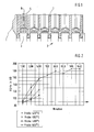
- an insert 1 is encapsulated with the cylinder liners of a crankcase 2 with a magnesium alloy 3.
- the sockets 1 consist e.g. from a conventionally precipitation-hardened Alusil casting alloy.
- an induction coil 4 is inserted into each socket 1 and extends over the entire length of the socket 1. Furthermore, a tube 5 is arranged within the induction coil 4, which has over its entire length on the circumference not shown outlet nozzles for the exit of the quenching agent.
- the diagram in FIG. 2 shows the Brinell hardness (HB) as a function of the solution annealing temperature and the holding time during inductive solution annealing.
- an induction plant was used for solution annealing.
- the specimens were quenched with water to room temperature and stored at 170 ° C for 8 h warm.
- the Brinell hardness (HB) was determined with a ball with a diameter of 2.5 cm, a test load of 62.5 kp with an exposure time of 30 s.
- a hardness of more than 100 HB is sufficient. Much higher hardness leads only to an undesirable brittleness of the tread. From the diagram of Figure 2 it can be seen that at a solution annealing temperature of 420 ° C to 450 ° C at a holding time of 5 min already the desired hardness is achieved.
Landscapes
- Chemical & Material Sciences (AREA)
- Engineering & Computer Science (AREA)
- Physics & Mathematics (AREA)
- Thermal Sciences (AREA)
- Crystallography & Structural Chemistry (AREA)
- Materials Engineering (AREA)
- Mechanical Engineering (AREA)
- Metallurgy (AREA)
- Organic Chemistry (AREA)
- Cylinder Crankcases Of Internal Combustion Engines (AREA)
Abstract
Description
- Die Erfindung bezieht sich auf ein Verfahren zum Ausscheidungshärten von hochlegierten Nichteisenmetallen. Sie hat auch eine Vorrichtung zur Durchführung des Verfahrens zum Gegenstand.
- Hochlegierte Nichteisenmetalle werden beispielsweise für Verbundbauteile verwendet. So stellt beispielsweise das Kurbelgehäuse eines Verbrennungsmotors ein Verbundbauteil dar, bei dem die Zylinderlaufflächen, die eine Komponente des Verbundbauteils bilden, mit einer Leichtmetalllegierung als zweiter Komponente, z.B. einer Magnesiumlegierung, umgossen sind. Die Laufbuchsen können dabei aus einer ausscheidungsgehärteten, übereutektischen Aluminium-Silizium-Gusslegierung bestehen.
- Aufgabe der Erfindung ist es, das Ausscheidungshärten von hochlegierten Nichteisenmetallen zu verbessern, insbesondere bei einem Verbundbauteil mit zwei Komponenten aus unterschiedlichen Legierungen, also z.B. einem Kurbelgehäuse mit Zylinderlaufbuchsen als der einen Komponente, die Härte der Oberfläche dieser einen Komponente zu erhöhen.
- Dies wird erfindungsgemäß mit dem im Anspruch 1 gekennzeichneten Verfahren erreicht. In den Unteransprüchen 2 bis 12 sind vorteilhafte Ausgestaltungen der Erfindung wiedergegeben. Der Anspruch 13 betrifft eine bevorzugte Ausführungsform einer Vorrichtung zur Durchführung des erfindungsgemäßen Verfahrens, welche nach dem Anspruch 14 weiter ausgestaltet wird.
- Das erfindungsgemäß ausscheidungsgehärtete hochlegierte Nichteisenmetall kann eine Aluminium- und/oder Magnesiumlegierung sein, insbesondere eine übereutektische Aluminium-Silizium-Legierung mit einem Siliziumgehalt von mindestens 12 Gew.-% bis beispielsweise 40 Gew.-%. Die Aluminiumlegierung enthält zudem vorzugsweise Kupfer, um intermetallische Phasen, wie Al2Cu, zu bilden.
- Die Erfindung kann insbesondere bei einem Verbundbauteil mit einer ersten Komponente aus dem hochlegierten Nichteisenmetall als erste Legierung und einer zweiten Komponente aus einer zweiten Legierung eingesetzt werden. Die erste Legierung wird dabei einer Ausscheidungshärtung unterworfen. Die zweite Legierung zeichnet sich demgegenüber dadurch aus, dass sie eine Gefügeumwandlung erleiden würde, wenn sie auf die gleiche Temperatur erwärmt wird, wie die Glühtemperatur zum Ausscheidungshärten der ersten Legierung. Um eine solche Gefügeumwandlung der zweiten Komponente zu verhindern, wird erfindungsgemäß die erste Komponente an der von der zweiten Komponente abgewandten Oberfläche lediglich einer kurzen Lösungsglühbehandlung unterworfen, und zwar einem induktiven Lösungsglühen mit einer Haltezeit von vorzugsweise maximal 10 min, insbesondere 1 min bis 5 min. Anschließend wird die zweite Komponente abgeschreckt und dann das Verbundbauteil ausgelagert.
- Durch diese Wärmebehandlung wird die erste Komponente gehärtet, ohne die Gefügestruktur oder andere Eigenschaften der zweiten Komponente negativ zu beeinflussen. Auch wird durch diese Wärmebehandlung ein Verzug des Verbundbauteils verhindert.
- Das induktive Lösungsglühen beruht darauf, dass durch eine schnelle Änderung eines Magnetfeldes im Oberflächenbereich des hochlegierten Nichteisenmetalls der ersten Komponente Wirbelströme induziert werden. Diese fließen innerhalb des Materials in einer annähernd kurzgeschlossenen Schleife und können daher sehr hohe Werte erreichen. Der Stromfluss verursacht am Innenwiderstand des Materials einen Spannungsabfall, wodurch Leistung umgesetzt werden kann. Das Material erwärmt sich also ohne direkte Zuführung von Wärmeenergie von selbst.
- Zum Abschrecken kann ein herkömmliches Abschreckmittel verwendet werden, z.B. Wasser. Dabei soll die erste Komponente so schnell wie möglich auf Raumtemperatur oder darunter abgekühlt werden.
- Das Auslagern des Bauteils kann durch Warmauslagern oder Kaltauslagern erfolgen. Das Warmauslagern wird z.B. bei 100 °C bis 200 °C mindestens 5 h durchgeführt. Das Kaltauslagern erfolgt bei Raumtemperatur für mehrere Tage.
- Die erste Komponente kann dabei eine Legierung sein, die durch konventionelle Wärmebehandlung bereits ausscheidungsgehärtet worden ist, bevor sie mit der zweiten Komponente verbunden wurde. D.h., bei einer Aluminiumlegierung als erster Komponente kann die Aluminiumlegierung einer konventionellen Wärmebehandlung durch Lösungsglühen z.B. in einem Kammerofen bei einer Temperatur zwischen 450 °C und 600 °C, insbesondere zwischen 520 °C und 560 °C, für 1 h bis 10 h, Abschrecken z.B. mit Wasser und Warmauslagern z.B. bei 100 °C bis 200 °C mindestens 5 h oder Kaltauslagern bei Raumtemperatur für mehrere Tage unterworfen worden sein. Die so ausscheidungsgehärtete erste Komponente kann dann mit der zweiten Komponente z.B. durch Umgießen verbunden werden.
- Für die erste und die zweite Komponente werden vorzugsweise Leichtmetalle verwendet, und zwar vorzugsweise Aluminium- und/oder Magnesiumgusslegierungen. Dabei kann die erste Komponente z.B. aus einer ausscheidungshärtbaren Aluminiumlegierung und die zweite Komponente aus einer anderen Aluminiumlegierung oder einer Magnesiumlegierung bestehen. Vorzugsweise wird für die erste Komponente eine übereutektische Aluminium-Silizium-Gusslegierung eingesetzt, d.h. eine Aluminiumlegierung mit einem Siliziumgehalt von mindestens 12 Gew.-%. Die verwendete Aluminiumlegierung enthält zudem vorzugsweise Kupfer, um intermetallische Phasen, wie Al2Cu, zu bilden.
- Beispielsweise kann das hochlegierte Nichteisenmetall bzw. die erste Legierung aus 12 bis 20 Gew.-% Silizium, 0,1 bis 10 Gew.-% Kupfer und 0,1 bis 5 Gew.-% Magnesium und Aluminium sowie unvermeidbare Verunreinigungen als Rest bestehen. Dabei kann es sich z.B. um Alusil (AlSi17Cu4Mg) handeln.
- Die Magnesiumlegierung enthält vorzugsweise 2 bis 15 Gew.-% Aluminium und insgesamt 0,1 bis 5 Gew.-% eines oder mehrerer Alkalimetalle (Kalzium, Strontium, Barium).
- Wenn das Verbundbauteil eine Aluminiumgusslegierung als erste Komponente und eine Magnesiumgusslegierung als zweite Komponente aufweist, reicht im Allgemeinen ein induktives Lösungsglühen zwischen 400 °C und 500 °C aus, um die Oberfläche der ersten Komponente hinreichend zu härten. Bei einer kurzen Haltezeit von vorzugsweise weniger als 10 min., insbesondere maximal 5 min, wird damit zusätzlich sichergestellt, dass die Gefügestruktur der zweiten Komponente aus der Magnesiumgusslegierung sich nicht ändert, insbesondere kein Schmelzen der Magnesiumlegierung erfolgt. Vorzugsweise wird die zweite Komponente aus der Magnesiumgusslegierung beim induktiven Lösungsglühen der ersten Komponente auf nicht mehr als 300 °C, insbesondere nicht mehr als 200 °C erwärmt. Zudem hat sich gezeigt, dass eine längere Haltezeit und damit höhere Härte zu einer unerwünschten Sprödigkeit der ersten Komponente führen kann.
- Wie erwähnt, kann die erste Komponente z.B. die Zylinderlaufbuchse eines Kurbelgehäuses sein, und die zweite Komponente die Legierung, mit der die Zylinderlaufbuchse umgossen ist. Stattdessen kann die erste Komponente auch durch ein anderes Insert gebildet sein, das von der zweiten Komponente ummantelt ist.
- Die Zylinderlaufbuchsen bilden dabei vorzugsweise ein Insert aus einer übereutektischen Aluminium-Silizium-Gusslegierung, wie Alusil, das konventionell ausgehärtet wird. Das Insert wird dann in die Gießform eingelegt und z.B. mit der flüssigen Magnesiumlegierung umgossen. Nach dem Ausscheidungshärten des Inserts als erste Komponente durch induktives Lösungsglühen wird das Innere der Laufbuchsen z.B. durch Honen und dergleichen nachbearbeitet.
- Das induktive Lösungsglühen wird mit einer Induktionsanlage durchgeführt, die wie ein sekundärseitig kurzgeschlossener Lufttrafo aufgebaut ist. Das Übersetzungsverhältnis (Primärwicklungen) muss an die Leitfähigkeit der ersten Komponente angepasst werden, da diese immer nur eine Sekundärwindung besitzt. Wie bei einem Tesla-Trafo ist eine ausreichende Energieübertragung nur bei höheren Frequenzen möglich. Dies beruht auf dem Induktionsgesetz, wonach die induzierte Spannung mit der Frequenz linear zunimmt. Als Induktionsanlage hat sich vor allem eine doppelhochfrequenzige Induktionsanlage als geeignet erwiesen, jedoch sind z.B. auch Mittelfrequenz-Anlagen einsetzbar.
- Das Bauteil, das dem erfindungsgemäßen Verfahren unterworfen wird, kann aus zwei oder mehreren Komponenten bestehen. Entscheidend ist lediglich, dass wenigstens eine Komponente induktiv lösungsgeglüht wird, während die anderen Komponenten aus einer Legierung bestehen, die durch das Lösungsglühen der einen Komponente keine Gefügeumwandlung erfahren.
- Nachstehend ist die Erfindung anhand der beigefügten Zeichnung beispielhaft näher erläutert. Darin zeigen:
- Figur 1
- einen Schnitt durch das Kurbelgehäuse eines Verbrennungsmotors; und
- Figur 2
- ein Diagramm, das die Härte eines Probekörpers in Abhängigkeit von der Lösungsglühtemperatur und der Haltezeit beim induktiven Lösungsglühen wiedergibt.
- Gemäß Figur 1 ist ein Insert 1 mit den Zylinderlaufbuchsen eines Kurbelgehäuses 2 mit einer Magnesiumlegierung 3 umgossen. Die Buchsen 1 bestehen z.B. aus einer konventionell ausscheidungsgehärteten Alusil-Gusslegierung.
- Wie anhand der linken Buchse 1 in Figur 1 gezeigt, wird in jede Buchse 1 eine Induktionsspule 4 eingeführt, die sich über die gesamte Länge der Buchse 1 erstreckt. Weiterhin ist ein Rohr 5 innerhalb der Induktionsspule 4 angeordnet, welches über seine gesamte Länge am Umfang nicht dargestellte Austrittsdüsen zum Austritt des Abschreckmittels aufweist.
- Das Diagramm in Figur 2 zeigt die Brinell-Härte (HB) in Abhängigkeit von der Lösungsglühtemperatur und der Haltezeit beim induktiven Lösungsglühen. Dabei wurden Probekörper von etwa 2 cm x 2 cm x 2 cm aus Alusil bei 420 °C, 450 °C, 480 °C und 500 °C zwischen 1 min und 5 min und in einem Fall (Probe 500 °C) bis 640 min induktiv lösungsgeglüht. Zum Lösungsglühen wurde eine Induktionsanlage verwendet.
- Die Probekörper wurden mit Wasser auf Raumtemperatur abgeschreckt und bei 170 °C 8 h warm ausgelagert.
- Die Brinell-Härte (HB) wurde mit einer Kugel mit einem Durchmesser von 2,5 cm, einer Prüfkraft von 62,5 kp bei einer Einwirkdauer von 30 s bestimmt.
- Für die Zylinderlauffläche eines Hubkolbenmotors ist eine Härte von mehr als 100 HB ausreichend. Wesentlich höhere Härten führen nur zu einer unerwünschten Sprödigkeit der Lauffläche. Aus dem Diagramm nach Figur 2 ist zu ersehen, dass bei einer Lösungsglühtemperatur von 420 °C bis 450 °C bei einer Haltezeit von 5 min bereits die gewünschte Härte erzielt wird.
Claims (14)
- Verfahren zum Ausscheidungshärten von hochlegierten Nichteisenmetallen, dadurch gekennzeichnet, dass das Ausscheidungshärten durch induktives Lösungsglühen mit nachfolgendem Abschrecken erfolgt.
- Verfahren nach Anspruch 1, dadurch gekennzeichnet, dass das Nichteisenmetall eine Aluminium- und/oder Magnesiumlegierung ist.
- Verfahren nach Anspruch 1 oder 2, dadurch gekennzeichnet, dass das Ausscheidungshärten der einen, ersten Komponente eines Verbundbauteils mit zwei Komponenten aus unterschiedlichen Legierungen durchgeführt wird, wobei die erste Komponente durch das hochlegierte Nichteisenmetall gebildet wird und die zweite Komponente aus einer Legierung besteht, die bei der Temperatur zum Ausscheidungsglühen der ersten Komponente einer Gefügeumwandlung ausgesetzt ist.
- Verfahren nach Anspruch 1 oder 3, dadurch gekennzeichnet, dass das hochlegierte Nichteisenmetall bzw. das Verbundbauteil nach dem induktiven Lösungsglühen und Abschrecken warm ausgelagert wird.
- Verfahren nach Anspruch 1 oder 3, dadurch gekennzeichnet, dass das hochlegierte Nichteisenmetall bzw. die erste Komponente aus einer ausscheidungsgehärteten Legierung besteht, bevor sie der weiteren Ausscheidungsaushärtung durch das induktive Lösungsglühen unterworfen wird.
- Verfahren nach einem der Ansprüche 3 bis 5, dadurch gekennzeichnet, dass die erste Komponente eine ausscheidungshärtbare Aluminiumlegierung und die zweite Komponente eine Aluminiumlegierung oder eine Magnesiumlegierung ist.
- Verfahren nach Anspruch 1, dadurch gekennzeichnet, dass das induktive Lösungsglühen bei einer Temperatur zwischen 400 °C und 500 °C erfolgt.
- Verfahren nach Anspruch 1, dadurch gekennzeichnet, dass das induktive Lösungsglühen mit einer Haltezeit von 0,5 min bis 10 min durchgeführt wird.
- Verfahren nach Anspruch 3, dadurch gekennzeichnet, dass die erste Komponente aus einer Aluminiumlegierung mit einem Siliziumgehalt von mindestens 12 Gew.-% und die zweite Komponente aus einer Magnesiumgusslegierung besteht, und die zweite Komponente beim induktiven Lösungsglühen einer Temperatur von maximal 300 °C ausgesetzt wird.
- Verfahren nach Anspruch 4, dadurch gekennzeichnet, dass das Warmauslagern des Verbundbauteils bei 100 °C bis 200 °C mindestens 6 h durchgeführt wird.
- Verfahren nach einem der Ansprüche 3 bis 10, dadurch gekennzeichnet, dass das Verbundbauteil ein hohles Insert als erste Komponente und als zweite Komponente eine Ummantelung des Inserts aufweist.
- Verfahren nach Anspruch 11, dadurch gekennzeichnet, dass das Verbundbauteil durch ein Kurbelgehäuse (2) eines Verbrennungsmotors gebildet wird, wobei das Insert (1) die Zylinderlaufbuchsen bildet und die Ummantelung (3) durch Umgießen der Inserts (1) mit der Legierung der zweiten Komponente gebildet wird.
- Vorrichtung zur Durchführung des Verfahrens nach Anspruch 12, gekennzeichnet durch in die Zylinderlaufbuchsen einführbare Induktionsspulen (4).
- Vorrichtung nach Anspruch 13, gekennzeichnet durch ein in jede Zylinderlaufbuchse einführbares Rohr (5) zur Zufuhr eines Abschreckmittels, das über seine gesamte Länge innerhalb der Zylinderlaufbuchse mit Austrittsdüsen für das Abschreckmittel versehen ist.
Applications Claiming Priority (1)
| Application Number | Priority Date | Filing Date | Title |
|---|---|---|---|
| DE102006006849A DE102006006849A1 (de) | 2006-02-15 | 2006-02-15 | Verfahren und Vorrichtung zum Ausscheidungshärten von hochlegierten Nichteisenmetallen |
Publications (2)
| Publication Number | Publication Date |
|---|---|
| EP1820871A1 true EP1820871A1 (de) | 2007-08-22 |
| EP1820871B1 EP1820871B1 (de) | 2012-12-05 |
Family
ID=38098582
Family Applications (1)
| Application Number | Title | Priority Date | Filing Date |
|---|---|---|---|
| EP07000735A Active EP1820871B1 (de) | 2006-02-15 | 2007-01-16 | Verfahren und Vorrichtung zum Ausscheidungshärten von hochlegierten Leichtmetallen mittels Induktion |
Country Status (2)
| Country | Link |
|---|---|
| EP (1) | EP1820871B1 (de) |
| DE (1) | DE102006006849A1 (de) |
Cited By (2)
| Publication number | Priority date | Publication date | Assignee | Title |
|---|---|---|---|---|
| WO2009043549A1 (de) * | 2007-09-26 | 2009-04-09 | Ks Aluminium Technologie Gmbh | Aluminium-silizium-gusslegierung für monolithische zylinderkurbelgehäuse |
| EP2371983A1 (de) * | 2010-03-25 | 2011-10-05 | Georg Fischer Verwaltungs-GmbH | Verfahren zur Vergütung eines Gussbauteils sowie Gussbauteil hergestellt nach dem Verfahren |
Families Citing this family (2)
| Publication number | Priority date | Publication date | Assignee | Title |
|---|---|---|---|---|
| DE102011105447B4 (de) * | 2011-06-24 | 2019-08-22 | Audi Ag | Verfahren zur Herstellung von Aluminium-Druckgussteilen |
| DE102016001209A1 (de) | 2016-02-03 | 2017-08-03 | Daimler Ag | Verfahren zum Härten eines Stahlbauteils sowie Antriebsstrangelement für ein Fahrzeug mit einem derart gehärteten Stahlbauteil |
Citations (5)
| Publication number | Priority date | Publication date | Assignee | Title |
|---|---|---|---|---|
| US4628167A (en) * | 1985-06-27 | 1986-12-09 | Tocco, Inc. | Apparatus for inductively hardneing the interior surface of objects |
| DE19611929C1 (de) * | 1996-03-27 | 1997-07-24 | Glyco Metall Werke | Schichtverbundwerkstoff und Verfahren zur Verbesserung der Oberflächenhärte von Schichtverbundwerkstoffen |
| EP1020540A1 (de) | 1999-01-16 | 2000-07-19 | Bayerische Motoren Werke Aktiengesellschaft | Verfahren zur Herstellung von Gussteilen aus Aluminiumlegierrungen |
| JP2003033859A (ja) | 2001-07-23 | 2003-02-04 | Honda Motor Co Ltd | シリンダブロックの製造方法 |
| WO2004101981A1 (de) * | 2003-05-17 | 2004-11-25 | Daimlerchrysler Ag | Verfahren zur vergütung von zylinderköpfen und zylinderköpfe für verbrennungsmotoren |
Family Cites Families (4)
| Publication number | Priority date | Publication date | Assignee | Title |
|---|---|---|---|---|
| AT309837B (de) * | 1968-02-27 | 1973-09-10 | Elin Union Ag | Verfahren zur Aushärtung von Legierungen |
| DE4013148C1 (de) * | 1990-04-25 | 1991-10-31 | Mercedes-Benz Aktiengesellschaft, 7000 Stuttgart, De | |
| DE19842608A1 (de) * | 1998-09-17 | 2000-03-23 | Ks Aluminium Technologie Ag | Verfahren zum Herstellen einer Verschleißschicht bei Zylinderlaufbahnen |
| DE19926229C1 (de) * | 1999-06-10 | 2001-02-15 | Vaw Ver Aluminium Werke Ag | Verfahren zum prozeßintegrierten Wärmebehandeln |
-
2006
- 2006-02-15 DE DE102006006849A patent/DE102006006849A1/de not_active Withdrawn
-
2007
- 2007-01-16 EP EP07000735A patent/EP1820871B1/de active Active
Patent Citations (5)
| Publication number | Priority date | Publication date | Assignee | Title |
|---|---|---|---|---|
| US4628167A (en) * | 1985-06-27 | 1986-12-09 | Tocco, Inc. | Apparatus for inductively hardneing the interior surface of objects |
| DE19611929C1 (de) * | 1996-03-27 | 1997-07-24 | Glyco Metall Werke | Schichtverbundwerkstoff und Verfahren zur Verbesserung der Oberflächenhärte von Schichtverbundwerkstoffen |
| EP1020540A1 (de) | 1999-01-16 | 2000-07-19 | Bayerische Motoren Werke Aktiengesellschaft | Verfahren zur Herstellung von Gussteilen aus Aluminiumlegierrungen |
| JP2003033859A (ja) | 2001-07-23 | 2003-02-04 | Honda Motor Co Ltd | シリンダブロックの製造方法 |
| WO2004101981A1 (de) * | 2003-05-17 | 2004-11-25 | Daimlerchrysler Ag | Verfahren zur vergütung von zylinderköpfen und zylinderköpfe für verbrennungsmotoren |
Cited By (2)
| Publication number | Priority date | Publication date | Assignee | Title |
|---|---|---|---|---|
| WO2009043549A1 (de) * | 2007-09-26 | 2009-04-09 | Ks Aluminium Technologie Gmbh | Aluminium-silizium-gusslegierung für monolithische zylinderkurbelgehäuse |
| EP2371983A1 (de) * | 2010-03-25 | 2011-10-05 | Georg Fischer Verwaltungs-GmbH | Verfahren zur Vergütung eines Gussbauteils sowie Gussbauteil hergestellt nach dem Verfahren |
Also Published As
| Publication number | Publication date |
|---|---|
| DE102006006849A1 (de) | 2007-08-16 |
| EP1820871B1 (de) | 2012-12-05 |
Similar Documents
| Publication | Publication Date | Title |
|---|---|---|
| EP0205828B1 (de) | Verfahren und Verwendung eines Stahles zur Herstellung von Stahlrohren mit erhöhter Sauergasbeständigkeit | |
| EP2855718B1 (de) | Stahlflachprodukt und verfahren zur herstellung eines stahlflachprodukts | |
| DE102011105447B4 (de) | Verfahren zur Herstellung von Aluminium-Druckgussteilen | |
| DE3810261C2 (de) | Verfahren zum Herstellen von Rohren, Stangen und Bändern | |
| DE4019845C2 (de) | Verfahren zur Herstellung einer Arbeitswalze für ein Metallwalzwerk | |
| EP2840159B1 (de) | Verfahren zum Herstellen eines Stahlbauteils | |
| DE102012214274A1 (de) | Vordiffundierte Al-Si-Beschichtungen zur Verwendung bei einer schnellen Induktionsaufheizung von pressgehärtetem Stahl | |
| DE102005035709A1 (de) | Kupferlegierung mit hoher Dämpfungskapazität und Verfahren zu ihrer Herstellung | |
| EP1820871B1 (de) | Verfahren und Vorrichtung zum Ausscheidungshärten von hochlegierten Leichtmetallen mittels Induktion | |
| WO2019002026A1 (de) | Verfahren zum herstellen eines mit einem überzug versehenen stahlbauteils und stahlbauteil | |
| WO2008074313A2 (de) | Kugelzapfen und -hülsen aus nichtrostendem stahl | |
| EP2554288B1 (de) | Verfahren und Werkzeug zur Wärmebehandlung von Aluminiumblechwerkstoff sowie nach einem derartigen Verfahren wärmebehandelter Aluminiumblechwerkstoff | |
| EP1462192A1 (de) | Verfahren zur Umformung einer Platine aus einem Vergütungsstahl und Vorrichtung zur Durchführung des Verfahrens | |
| DE19901508A1 (de) | Verfahren zur Herstellung von Gußteilen aus Aluminiumlegierungen | |
| DE10322309B4 (de) | Zylinderkopf für Verbrennungsmotoren und Verfahren zu dessen Herstellung | |
| WO2009106327A1 (de) | Verfahren zum wärmebehandeln und beschichten eines bauteils sowie nach dem verfahren hergestelltes bauteil | |
| DE3832014A1 (de) | Verfahren zur herstellung hochfester nahtloser stahlrohre | |
| DE102012010696B4 (de) | Wärmebehandlungsverfahren für eine Vielzahl von Leichtmetallbauteilen | |
| DE60300101T2 (de) | Verfahren zur Wärmebehandlung von TiAl-Legierungen | |
| DE2739264A1 (de) | Verfahren zur herstellung von rohren aus hochfestem stahl | |
| DE102020003877A1 (de) | Verfahren zum Herstellen eines Bauteils, insbesondere für ein Kraftfahrzeug sowie Bauteil | |
| DE102016208485A1 (de) | Verfahren zur Herstellung von Gleitlagerverbundwerkstoffen, Gleitlagerverbundwerkstoff und Gleitelement aus solchen Gleitlagerverbundwerkstoffen | |
| AT504089B1 (de) | Aluminiumlegierung und verfahren zu deren herstellung | |
| WO2010100106A1 (de) | Verfahren und vorrichtung zum induktions-härten von kurbelwellen | |
| DE2601067A1 (de) | Verfahren zum feuertauchbad-aluminieren von kompakten erzeugnissen aus eisenlegierungen |
Legal Events
| Date | Code | Title | Description |
|---|---|---|---|
| PUAI | Public reference made under article 153(3) epc to a published international application that has entered the european phase |
Free format text: ORIGINAL CODE: 0009012 |
|
| AK | Designated contracting states |
Kind code of ref document: A1 Designated state(s): AT BE BG CH CY CZ DE DK EE ES FI FR GB GR HU IE IS IT LI LT LU LV MC NL PL PT RO SE SI SK TR |
|
| AX | Request for extension of the european patent |
Extension state: AL BA HR MK YU |
|
| 17P | Request for examination filed |
Effective date: 20070906 |
|
| 17Q | First examination report despatched |
Effective date: 20071108 |
|
| AKX | Designation fees paid |
Designated state(s): DE FR GB IT |
|
| REG | Reference to a national code |
Ref country code: DE Ref legal event code: R079 Ref document number: 502007010967 Country of ref document: DE Free format text: PREVIOUS MAIN CLASS: C22F0001043000 Ipc: C21D0009000000 |
|
| RIC1 | Information provided on ipc code assigned before grant |
Ipc: C21D 1/10 20060101ALI20120522BHEP Ipc: C21D 9/00 20060101AFI20120522BHEP Ipc: C22F 1/04 20060101ALI20120522BHEP Ipc: C22F 1/06 20060101ALI20120522BHEP |
|
| GRAP | Despatch of communication of intention to grant a patent |
Free format text: ORIGINAL CODE: EPIDOSNIGR1 |
|
| GRAS | Grant fee paid |
Free format text: ORIGINAL CODE: EPIDOSNIGR3 |
|
| GRAA | (expected) grant |
Free format text: ORIGINAL CODE: 0009210 |
|
| AK | Designated contracting states |
Kind code of ref document: B1 Designated state(s): DE FR GB IT |
|
| REG | Reference to a national code |
Ref country code: GB Ref legal event code: FG4D Free format text: NOT ENGLISH |
|
| REG | Reference to a national code |
Ref country code: DE Ref legal event code: R096 Ref document number: 502007010967 Country of ref document: DE Effective date: 20130131 |
|
| PLBE | No opposition filed within time limit |
Free format text: ORIGINAL CODE: 0009261 |
|
| STAA | Information on the status of an ep patent application or granted ep patent |
Free format text: STATUS: NO OPPOSITION FILED WITHIN TIME LIMIT |
|
| 26N | No opposition filed |
Effective date: 20130906 |
|
| REG | Reference to a national code |
Ref country code: DE Ref legal event code: R097 Ref document number: 502007010967 Country of ref document: DE Effective date: 20130906 |
|
| REG | Reference to a national code |
Ref country code: FR Ref legal event code: PLFP Year of fee payment: 10 |
|
| REG | Reference to a national code |
Ref country code: FR Ref legal event code: PLFP Year of fee payment: 11 |
|
| REG | Reference to a national code |
Ref country code: FR Ref legal event code: PLFP Year of fee payment: 12 |
|
| P01 | Opt-out of the competence of the unified patent court (upc) registered |
Effective date: 20230502 |
|
| PGFP | Annual fee paid to national office [announced via postgrant information from national office to epo] |
Ref country code: GB Payment date: 20260122 Year of fee payment: 20 |
|
| PGFP | Annual fee paid to national office [announced via postgrant information from national office to epo] |
Ref country code: DE Payment date: 20260121 Year of fee payment: 20 |
|
| PGFP | Annual fee paid to national office [announced via postgrant information from national office to epo] |
Ref country code: IT Payment date: 20260130 Year of fee payment: 20 |
|
| PGFP | Annual fee paid to national office [announced via postgrant information from national office to epo] |
Ref country code: FR Payment date: 20260128 Year of fee payment: 20 |