EP1817605B1 - Systems, methods, and apparatus for jammer rejection - Google Patents
Systems, methods, and apparatus for jammer rejection Download PDFInfo
- Publication number
- EP1817605B1 EP1817605B1 EP05852691A EP05852691A EP1817605B1 EP 1817605 B1 EP1817605 B1 EP 1817605B1 EP 05852691 A EP05852691 A EP 05852691A EP 05852691 A EP05852691 A EP 05852691A EP 1817605 B1 EP1817605 B1 EP 1817605B1
- Authority
- EP
- European Patent Office
- Prior art keywords
- peaks
- peak
- code
- frequency
- signal
- Prior art date
- Legal status (The legal status is an assumption and is not a legal conclusion. Google has not performed a legal analysis and makes no representation as to the accuracy of the status listed.)
- Expired - Lifetime
Links
Images


Classifications
-
- G—PHYSICS
- G01—MEASURING; TESTING
- G01S—RADIO DIRECTION-FINDING; RADIO NAVIGATION; DETERMINING DISTANCE OR VELOCITY BY USE OF RADIO WAVES; LOCATING OR PRESENCE-DETECTING BY USE OF THE REFLECTION OR RERADIATION OF RADIO WAVES; ANALOGOUS ARRANGEMENTS USING OTHER WAVES
- G01S19/00—Satellite radio beacon positioning systems; Determining position, velocity or attitude using signals transmitted by such systems
- G01S19/01—Satellite radio beacon positioning systems transmitting time-stamped messages, e.g. GPS [Global Positioning System], GLONASS [Global Orbiting Navigation Satellite System] or GALILEO
- G01S19/13—Receivers
- G01S19/21—Interference related issues ; Issues related to cross-correlation, spoofing or other methods of denial of service
-
- G—PHYSICS
- G01—MEASURING; TESTING
- G01S—RADIO DIRECTION-FINDING; RADIO NAVIGATION; DETERMINING DISTANCE OR VELOCITY BY USE OF RADIO WAVES; LOCATING OR PRESENCE-DETECTING BY USE OF THE REFLECTION OR RERADIATION OF RADIO WAVES; ANALOGOUS ARRANGEMENTS USING OTHER WAVES
- G01S19/00—Satellite radio beacon positioning systems; Determining position, velocity or attitude using signals transmitted by such systems
- G01S19/01—Satellite radio beacon positioning systems transmitting time-stamped messages, e.g. GPS [Global Positioning System], GLONASS [Global Orbiting Navigation Satellite System] or GALILEO
- G01S19/13—Receivers
- G01S19/34—Power consumption
-
- G—PHYSICS
- G01—MEASURING; TESTING
- G01S—RADIO DIRECTION-FINDING; RADIO NAVIGATION; DETERMINING DISTANCE OR VELOCITY BY USE OF RADIO WAVES; LOCATING OR PRESENCE-DETECTING BY USE OF THE REFLECTION OR RERADIATION OF RADIO WAVES; ANALOGOUS ARRANGEMENTS USING OTHER WAVES
- G01S19/00—Satellite radio beacon positioning systems; Determining position, velocity or attitude using signals transmitted by such systems
- G01S19/01—Satellite radio beacon positioning systems transmitting time-stamped messages, e.g. GPS [Global Positioning System], GLONASS [Global Orbiting Navigation Satellite System] or GALILEO
- G01S19/03—Cooperating elements; Interaction or communication between different cooperating elements or between cooperating elements and receivers
-
- G—PHYSICS
- G01—MEASURING; TESTING
- G01S—RADIO DIRECTION-FINDING; RADIO NAVIGATION; DETERMINING DISTANCE OR VELOCITY BY USE OF RADIO WAVES; LOCATING OR PRESENCE-DETECTING BY USE OF THE REFLECTION OR RERADIATION OF RADIO WAVES; ANALOGOUS ARRANGEMENTS USING OTHER WAVES
- G01S19/00—Satellite radio beacon positioning systems; Determining position, velocity or attitude using signals transmitted by such systems
- G01S19/01—Satellite radio beacon positioning systems transmitting time-stamped messages, e.g. GPS [Global Positioning System], GLONASS [Global Orbiting Navigation Satellite System] or GALILEO
- G01S19/13—Receivers
- G01S19/22—Multipath-related issues
-
- G—PHYSICS
- G01—MEASURING; TESTING
- G01S—RADIO DIRECTION-FINDING; RADIO NAVIGATION; DETERMINING DISTANCE OR VELOCITY BY USE OF RADIO WAVES; LOCATING OR PRESENCE-DETECTING BY USE OF THE REFLECTION OR RERADIATION OF RADIO WAVES; ANALOGOUS ARRANGEMENTS USING OTHER WAVES
- G01S19/00—Satellite radio beacon positioning systems; Determining position, velocity or attitude using signals transmitted by such systems
- G01S19/01—Satellite radio beacon positioning systems transmitting time-stamped messages, e.g. GPS [Global Positioning System], GLONASS [Global Orbiting Navigation Satellite System] or GALILEO
- G01S19/13—Receivers
- G01S19/24—Acquisition or tracking or demodulation of signals transmitted by the system
- G01S19/29—Acquisition or tracking or demodulation of signals transmitted by the system carrier including Doppler, related
-
- H—ELECTRICITY
- H04—ELECTRIC COMMUNICATION TECHNIQUE
- H04B—TRANSMISSION
- H04B1/00—Details of transmission systems, not covered by a single one of groups H04B3/00 - H04B13/00; Details of transmission systems not characterised by the medium used for transmission
- H04B1/69—Spread spectrum techniques
- H04B1/707—Spread spectrum techniques using direct sequence modulation
- H04B1/7073—Synchronisation aspects
- H04B1/7075—Synchronisation aspects with code phase acquisition
- H04B1/7077—Multi-step acquisition, e.g. multi-dwell, coarse-fine or validation
-
- H—ELECTRICITY
- H04—ELECTRIC COMMUNICATION TECHNIQUE
- H04K—SECRET COMMUNICATION; JAMMING OF COMMUNICATION
- H04K3/00—Jamming of communication; Counter-measures
- H04K3/20—Countermeasures against jamming
- H04K3/22—Countermeasures against jamming including jamming detection and monitoring
- H04K3/224—Countermeasures against jamming including jamming detection and monitoring with countermeasures at transmission and/or reception of the jammed signal, e.g. stopping operation of transmitter or receiver, nulling or enhancing transmitted power in direction of or at frequency of jammer
- H04K3/228—Elimination in the received signal of jamming or of data corrupted by jamming
Definitions
- This invention relates to wireless signal reception.
- radio-location and time transfer is the NAVSTAR Global Positioning System (GPS) as described in the Global Positioning Service Signal Specification (2nd ed., 1995, USCG Navigation Center, Alexandria, VA ).
- GPS Global Positioning Service Signal Specification
- Other examples include the GLONASS GPS maintained by the Russian Republic and the GALILEO system proposed in Europe.
- Typical uses for radio-location systems include airborne and oceanic navigation, although other uses for such systems are becoming increasingly common.
- Ground-based systems such as networks for cellular telephony may also be used for radio-location and time transfer.
- Examples of terrestrial applications for radio-location technologies include asset tracking (for example, tracking of trucks and railcars), time transfer (for example, between fixed and mobile units of a cellular telephone network), locating cellular telephone users for emergency services (for example, as part of an "enhanced 911" initiative), and highway navigation assistance.
- the C/A codes are Gold codes which are selected for their autocorrelation properties.
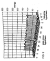
- FIGURE 1 shows a portion of the autocorrelation function of GPS PRN 1, which has a magnitude below 0.1 for all code offsets from + 1 to + 511 and from -1 to - 511.
- a NAVSTAR GPS SV may also transmit messages via a 10.23 MHz P(Y) code modulated onto a carrier at 1.22760 GHz (also called the L2 frequency).
- a GPS SV may transmit messages in a similar manner via several other carriers and/or codes as well.
- One common use of GPS signals is to support position location operations by terrestrial receivers. Typically, signals from at least four SVs are needed to resolve a position in three dimensions.
- a GPS signal as received by a terrestrial user is exceedingly weak.
- the received power of a GPS signal at the earth's surface is -130 dBm.
- the thermal noise level is -111 dBm, or nearly 20 dB higher.
- a receiver inside a building may be expected to experience an additional 20 dB of signal attenuation from concrete and other building materials, such that a GPS signal received indoors may be about 40 dB bellow the thermal noise level.
- an interfering signal well below the thermal noise level may be sufficient to prevent a GPS receiver from detecting a valid signal, despite the strong autocorrelation properties of the C/A codes.
- US 2003/193992 A1 which describes a spread spectrum wireless device that may include a receiver, a searcher, a search controller and other features.
- the search controller selectively generates control signals to control the searcher, which searches for a spread-spectrum signal.
- the architecture of the searcher is dynamically configurable by the search controller to selectively search multiple channels using multiple frequency bins for the signal.
- searcher hardware is multiplexed to perform simultaneous searches in either an IS-95 CDMA mode or a GPS mode.
- the search hardware is time-multiplexed into a number of searcher time slices, each of which can generate a PN sequence to despread a data sequence.
- the search hardware is configured as a number of distinct GPS channels, each of which can generate a Gold code sequence for tracking a GPS signal from a particular GPS satellite. This configuration allows the searcher to perform multiple GPS signal searches simultaneously. Signal searching in both IS-95 and GPS modes is performed at significantly higher speeds compared to conventional searcher hardware.
- the search hardware can be dynamically configured to operate in either the IS-95 or the GPS mode, eliminating the need for dedicated circuitry for each mode of operation.
- a method of signal processing includes obtaining a plurality of results based on correlating a received code with a reference code.
- Each of the results corresponds to one of a plurality of code phase hypotheses and one of a plurality of frequency hypotheses.
- the method includes selecting a plurality of peaks among the results for the frequency hypothesis.
- the method includes storing a list of the selected plurality of peaks. Further embodiments include rejecting a frequency hypothesis based on the corresponding list.
- the received code is obtained from a signal received from a GPS SV.
- FIGURE 1 is a plot showing a portion of the autocorrelation function of a GPS C/A code.
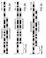
- FIGURES 2A-2C show comparisons of received codes with a reference code.
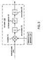
- FIGURE 3 shows a block diagram of one example of a correlator 100 and a reference code generator 110.
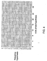
- FIGURE 5 is an energy plot showing a peak as may be obtained from a line-of-sight signal.
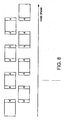
- FIGURE 6 is an energy plot showing several peaks due to multipath instances of the same transmitted signal.
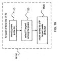
- FIGURE 10 is a flowchart of a method M100 according to an embodiment.
- FIGURE 13B is a flowchart of a method M300 according to an embodiment.
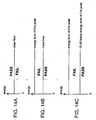
- FIGURES 14B and 14C are figures showing pass and fail regions of an implementation of list energy distribution test task T600.
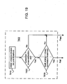
- FIGURE 19 is a flowchart of an implementation T802 of cross-correlation test task T800.
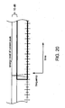
- FIGURE 20 is a diagram showing an example of a mask as used in an implementation of sidelobe test task T900.
- FIGURE 22 is a block diagram of an implementation 262 of a baseband processor 260 in one context.
- FIGURE 23 is a block diagram of an implementation of receiving device 202.
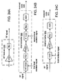
- FIGURE 24A is a block diagram of an example 310 of RF front end.
- FIGURE 25 is a block diagram of an implementation 302 of communications device 300.
- the term "obtaining” includes such ordinary meanings as calculating, deriving, and/or retrieving (e.g. from a memory or other storage or from another device).
- Embodiments include methods and apparatus that may be used in identifying a location of a signal in a two-dimensional search space. Such uses may include identifying a code phase and frequency of a received signal. The identified information may be further applied to operations such as acquisition and/or tracking of the signal. Code phase information may also be used in timing operations, such as the synchronization of one or more other processes.
- a receiving device may be configured to receive signals from one or more of a system of positioning satellites, such as the NAVSTAR GPS. Additionally or alternatively, a receiving device according to an embodiment may be configured to receive and/or transmit information (e.g. voice and/or data) over a network for wireless communications. Such a device may be configured to receive and/or transmit information via one or more channels in a code-division-multiple-access (CDMA) system.
- CDMA code-division-multiple-access
- a receiving device may perform some or all of the functions of a subscriber unit, access terminal (AT), base transceiver station (BTS), and/or user equipment (UE) according to at least a portion of one or more of the following standards or formats as promulgated by TIA, EIA, 3GPP, 3GPP2, CWTS (China), ARIB (Japan), TTC (Japan), TTA (Korea), ITU, and/or ETSI (Europe): CDMA, TD-SCDMA, W-CDMA (e.g.
- cdma2000 3x
- 3GPP2 cdma2000 e.g. TR-45.5, C.S0005-A, C.S0024
- IMT-2000 IMT-2000.
- Such a receiver or transceiver may be configured to communicate over bands at or near, e.g., 800MHz, 1800 MHz, and/or 1900 MHz.
- Such a receiver or transceiver may be configured to communicate via, for example, an M-ary form of phase-shift keying (PSK) such as binary PSK (BPSK), quadrature PSK (QPSK), offset QPSK (OQPSK), quadrature amplitude modulation (QAM), offset QAM (OQAM), minimum-shift keying (MSK), or Gaussian MSK (GMSK).
- PSK phase-shift keying
- BPSK binary PSK
- QPSK quadrature PSK
- OFQPSK offset QPSK
- QAM quadrature amplitude modulation
- MSK minimum-shift keying
- GMSK Gaussian MSK
- Methods for radio-location and/or time transfer include receiving a signal that has a predetermined code (i.e. a sequence of symbols), such as a GPS or CDMA signal.
- the predetermined code may be a repeating code, such as a GPS C/A code.
- the predetermined code may be a code that does not repeat or that has a very long period, such as a GPS P(Y) code.
- the original code will be a sequence of binary symbols such as +1 and -1 (as in a GPS C/A code), although such a code as received may include values ranging from one of the symbol values to the other.
- the received code may have a complex value, with each component having a value that ranges from one symbol value to the other (e.g. from about +1 to -1). At least some embodiments may also be applied to situations in which the original code is not a binary sequence.
- the predetermined code may be a pseudonoise (PN) sequence or to otherwise have a noise-like autocorrelation property (for example, as shown in FIGURE 1 ), such that correlation of the code as received with a reference copy of the code may be expected to yield a well-defined peak.
- the received signal may also be data-modulated.
- the received signal may be a spread spectrum signal in which the predetermined code is used to spread the bandwidth of a data stream, with the spread data stream then being used to modulate a carrier (via, for example, a PSK modulation).
- FIGURE 2A shows an example of a comparison between a predetermined code S1 as received (beginning at time index 0) and a reference copy SR of the code (hereinafter referred to as the "reference code").
- the reference code hereinafter referred to as the "reference code”
- filled squares indicate one binary symbol (e.g. +1) and open squares indicate the other binary symbol (e.g. -1). It may be seen that in the example of FIGURE 2A , the two codes are not aligned.
- the code phase may be used as an indication of the delay of the received signal, which in turn may be used as a measure of the distance between transmitter and receiver. Additionally or alternatively, the code phase may be used in synchronizing operations relating to the reception and/or transmission of one or more other signals. For example, timing information derived from the code phase may be used to synchronize the receiver to a slotted access channel. Examples of a slotted access channel include an access channel, which may be transmitted by the transmitter of the received code (e.g. on a downlink or reverse link), and a paging channel, which may be monitored by a receiver at that location (e.g. on an uplink or forward link).
- a slotted access channel include an access channel, which may be transmitted by the transmitter of the received code (e.g. on a downlink or reverse link), and a paging channel, which may be monitored by a receiver at that location (e.g. on an uplink or forward link).
- Correlation of the received code sequence with the reference code may be performed in the time domain by integrating the product of the received and reference codes over some portion of the length of the reference code:
- the received code will be a complex baseband signal, such that the correlation is performed for each of the I and Q components of the received code.
- a correlation result of the received signal and reference code for a given offset may be obtained by convolving the signal with, for example, a matched filter of the complex reference code r + jr (i.e. a filter having an impulse response that is the time-reversed complex conjugate of the reference code):
- the results of expressions (1) and (2) over a range of offsets will have the shape of a sinc function. While correlation results obtained using either expression (and/or another expression of the degree of correlation of the two codes) may be used as an energy result for the corresponding offset, typically the energy result is calculated as the sum of the squares of such correlation results for the I and Q components.
- the result of such a calculation over a range of offsets will have the shape of a (sinc) 2 function, whose peak is sharper and thus more localized than that of a sinc function.
- x I is the in-phase component of the received code
- x Q is the quadrature component of the received code
- e(t) is the energy result at offset t.
- the energy results may be fixed-point or floating-point values, and they may be in arbitrary units, e.g. in a case where the energy results are used only to determine relative differences between the peaks.
- the measurement scale may be selected as appropriate for such a task or tasks.
- correlator 100 may also be implemented to perform parallel correlation (multiplying more than one bit of the codes at the same time) or any combination of serial and parallel operation.
- a GPS receiver may include multiple instances of correlator 100, each receiving a copy of the reference code having a different corresponding delay, to obtain results for more than one code phase hypothesis at a time. Multiple instances of correlator 100 may also be used to search on more than one reference code at a time.
- a module including one or more correlators and logic (e.g. a processor) configured to control the correlators to obtain energy results for a desired set of hypotheses may be called a searcher or a means for searching.
- symbols of a code as received may be somewhat ambiguous. Nevertheless, the complexity of the correlation and/or energy calculations may be reduced somewhat according to the nature of the reference code and the criteria of the particular application.
- the result of multiplying a received symbol with a reference code symbol is either the received symbol or its inverse. If the associated loss in signal-to-noise ratio is acceptable, the received symbol may even be classified as +1 or -1, such that the multiplication may be reduced to an XOR operation.
- Embodiments include systems, methods, and apparatus that employ these and similar optimizations.
- Calculation of an energy result as described above may be repeated for each offset (or "code phase hypothesis") to be considered.
- code phase hypothesis In the GPS C/A code phase circle, there are 1023 possible hypotheses (or 2046 hypotheses at a resolution of 1 ⁇ 2 chip).
- the number of hypotheses to be searched may be greatly reduced by applying knowledge of the code phase location of the received code as obtained from previous searches and/or from an external source (such as a position determination entity or PDE).
- the search may be reduced to a width of, for example, 256 chips or 32 chips or less.
- correlation and/or energy results for the various code phase hypotheses may be obtained via operations in the frequency domain.
- the entire code phase circle may be efficiently searched at a selected resolution by, for example, transforming the received code into the frequency domain (e.g. using a discrete Fourier transform (DFT) operation such as a fast Fourier transform (FFT)), multiplying the transformed signal with a matched filter of the reference code, and applying an inverse transform to obtain the corresponding results in the time domain.
- DFT discrete Fourier transform
- FFT fast Fourier transform
- Some frequency-domain correlation techniques may also be used to perform a more narrow search in the frequency domain. For example, U.S. Published Patent Application No. 2004/0141574 (Akopian, published July 22, 2004 ) purports to describe a frequency-domain method for searching over a limited range of code phases.
- an appropriate correlator e.g. a set of logic elements, such as transistors and/or gates, programmed or otherwise arranged to perform FFT, IFFT, and associated operations
- FFT Fast Fourier Transform
- IFFT IFFT-IFFT
- a receiving device may also be desirable for a receiving device to determine the signal's location in frequency space.
- the Doppler shift due to the combined movement of the SV and user relative to one another amounts to about +/- 2.7 ppm.
- Frequency error of one or more oscillators at the receiver may add about another 2 ppm, for a total of 4.7 ppm of frequency uncertainty (alternatively, local oscillator error may be corrected at least somewhat, e.g. with a PLL or other correction loop).
- This 4.7 ppm corresponds to about +/- 7.5 kHz at the L1 carrier frequency of 1.57542 GHz. Filters may be used to remove frequency components outside that range.
- a receiving device may also search for the signal in frequency space.
- Many techniques and corresponding correlator and searcher structures may be used to obtain search results in two dimensions using operations in the time domain and/or in the frequency domain.
- correlation is performed in the time domain for a particular code phase hypothesis, and the result is transformed to the frequency domain (e.g. using a DFT or FFT) where the desired range of frequency hypotheses are searched for that code phase hypothesis.
- Such an operation may be repeated across the desired range of code phase hypotheses.
- coherent integration may be accomplished by summing correlation or energy results over more than one consecutive code period of the received code, and in the frequency domain it may be performed by summing each of the frequency components over time.
- coherent integration of the signal is typically limited to twenty milliseconds. If the data is known a priori, it may be removed from the signal (a process called data wipeoff or modulation wipeoff), and the coherent integration period may be extended to 40 milliseconds or even up to 160 milliseconds or more. Non-coherent integration may also be applied to combine results from non-consecutive code periods, or coherent integration periods, up to 88 or more times. In a communications device having an integrated GPS receiving device, the integration time may be limited by a maximum tune-away time relating to requirements of the communications channel.
- Data transmitted on a GPS C/A signal is largely redundant, and data to support modulation wipeoff may be provided by an external unit such as a PDE.
- a PDE may provide related information such as which SVs are currently visible and their approximate code phases and Dopplers.
- a PDE may also be configured to request a GPS receiving device to initiate a search. Communication between a GPS receiving device and a PDE may take place over a network for cellular communications (for example, via a cellular telephone transceiver with which a GPS receiver is integrated).
- the spacings and ranges of the code and/or frequency hypotheses may be varied based on factors such as strength of the desired SV signal, interfering signal strength, range of code phase and frequency uncertainty, desired accuracy, desired probability of detection, and desired time-to-fix.
- Typical code phase spacings include 1 chip, 1 ⁇ 2 chip, and 1 ⁇ 4 chip.
- Typical frequency ranges include +/- 31.25 Hz, 62.5 Hz, 125 Hz, and 250 Hz, with the range being divided into e.g. twenty frequency bins. Smearing of received energy across two or more code phase and/or frequency bins may occur if the integration period is too long. Smearing of received energy across two or more frequency bins may also occur if the spacing in the frequency domain is too narrow.
- a receiving device may be configured to perform searches according to a selectable one of several different search modes distinguished by such characteristics as frequency spacing and integration lengths.
- a search operation may include a low-resolution, wide-range search followed by one or more searches at a finer resolution. Searching may be performed for initial code acquisition, with subsequent tracking being done using a timing loop. In other applications, acquisition of the code may be sufficient.
- the code phase of the received code may be used to derive a measurement of time-of-arrival of the received code (or "pseudorange"), and pseudoranges from several SVs may be combined to obtain a position in space.
- a received signal may carry more than one code. For example, at any location on the earth's surface there may be up to twelve different GPS SVs visible, such that a GPS signal as received may include codes transmitted by more than one SV.
- a GPS receiving device will typically search for four, eight, or more SVs at once. Such searches, which may be performed on the same portion of a received signal, may be conducted serially and/or in parallel.
- a search may be conducted (for example, according to a search window of D frequency hypotheses by C code hypotheses) to obtain a grid of D x C energy results, each result corresponding to one of the D frequency hypotheses and one of the C code hypotheses.
- FIGURE 5 shows an example of a peak within an energy grid of twenty Doppler bins, each bin having 64 code hypotheses.
- adjacent code phase hypotheses are 1 ⁇ 2-chip apart, such that the grid extends across 32 chips in code space.
- the energy peak in this figure indicates the presence of the selected SV signal at code phase hypothesis 16 in Doppler bin 10.
- a GPS receiving device or a searcher within such a device may produce energy grids for several different corresponding SVs from the same portion of a received signal, with the grids possibly having different dimensions.
- a received signal may include versions of the same transmitted signal that propagate over different paths to arrive at the receiver at different times. Correlation of such a received signal with the corresponding reference code may result in several peaks at different grid points, each peak due to a different instance (also called a multipath) of the transmitted signal. These multipath peaks will usually fall within the same Doppler bin, unless the relative velocity between transmitter and receiver changes significantly with respect to the delays among the various multipaths.
- FIGURE 6 shows an example in which several peaks due to multipath instances of a transmitted signal are all located in the same Doppler bin.
- the receiving device may be self-jamming. That is, the jamming signal may arise from an internal source.
- Common internal jammers include clock spurs or leakage from an internal oscillator such as a phase-locked loop (PLL), a voltage-controlled oscillator (VCO), a local oscillator (LO) or another oscillator or clock circuit used for frequency conversion and/or for clocking of a digital logic circuit such as a processor.
- PLL phase-locked loop
- VCO voltage-controlled oscillator
- LO local oscillator
- a jamming signal may also arise from an external source, such as a clock spur or oscillator leakage from a nearby GPS receiver.
- the peak having the highest energy within the grid would correspond to the valid correlation, so that locating the code among the various hypotheses would simply be a matter of finding the peak with the highest energy.
- the highest peak within a grid may not be the most accurate. Therefore it is desirable to conduct additional processing of at least some of the grid values to locate the received code.
- a searcher or its processing logic
- Such a searcher may be configured to extract enough information from the grid to support a search for the best peak, and to store this information or to otherwise provide it to another unit (e.g. to be stored and processed), before allowing the grid to be overwritten.
- the operations of directing the search and reporting the peaks may be executed by one processing unit (e.g. in firmware), while the operations of determining which is the best one may be executed by another processing unit (e.g. in software) that cannot access the full grid.
- the information stored includes a maximum peak list, or a list of the strongest peaks of the grid (for example, the ten peaks having the highest energies) and the code phase and frequency hypotheses to which they correspond.
- a large search may be performed by segmenting the desired search space, in either or both dimensions, into several smaller windows. For example, results from search windows that are adjacent in code space may be combined to effectively create a larger search window in code space. In such manner, eight 32-chip windows (each covering e.g. 64 hypotheses) may be combined to create an effective window of about 256 chips (e.g. about 512 hypotheses). Likewise, results from search windows that are adjacent in frequency space may be combined to effectively create a larger search window in frequency space.
- an overlap of at least one hypothesis may be desired so that it may be determined whether a hypothesis at the edge of a grid is a local maximum.
- this description refers to the notion of a grid of energy values, it should be understood that it may not be necessary for all of the values in such a grid to exist at any one moment. While some values are being processed (for example, according to an implementation of method M100), other values of the "grid” may not yet have been calculated, while values of the "grid” that have already been processed may have been replaced. Indeed, even within a bin it may not be necessary for all of the values to exist at any one moment, and processing of a bin according to some implementations of method M100 may begin before all bin values are available.
- Task T110 identifies peaks in the bin. For example, task T110 may be implemented to classify as peaks those energy results which are local maxima in code phase space and in frequency space. Task T110 may skip the first and/or last code phase hypotheses for each bin, as sufficient information to determine whether the results at these points are local maxima may not be available. However, it may be desired to perform task T110 such that results at grid points which are excluded from method M100 are still considered in determining whether a result under test is a local maximum. In some implementations of task T110, computational complexity may be reduced by skipping (in code phase and/or in frequency) grid points that are adjacent to identified local maxima in either dimension.
- Task T130 returns a sorted list of the P largest peaks of the bin. For example, task T130 may sort each peak list and forward the sorted peak lists to another task for further processing.
- method M100 is performed by a first array of logic elements (e.g. an embedded processor) according to a firmware program, and task T130 passes the sorted bin lists to a second array of logic elements (e.g. a microprocessor) for further processing according to a software program. Sorting of the bin peak lists may already be accomplished with the completion of task T120, as a peak list may be sorted as each peak is selected.
- a first array of logic elements e.g. an embedded processor
- a second array of logic elements e.g. a microprocessor
- task T260 compares the energy value of the peak to that of n(P). If the energy value of the peak is greater than n(P), task T270 replaces entry n(P) with the peak and re-sorts the entries n(1)-n(P) by energy in decreasing order of magnitude.
- method M110 is performed by a module (e.g. a search processor, which may be an array of logic elements such as a dedicated or embedded processor) according to a routine in firmware, and the resulting list is stored or otherwise made available to another module (e.g. an array of logic elements such as a microprocessor) for further processing according to a routine in software.
- a module e.g. a search processor, which may be an array of logic elements such as a dedicated or embedded processor
- the resulting list is stored or otherwise made available to another module (e.g. an array of logic elements such as a microprocessor) for further processing according to a routine in software.
- an energy grid may include peaks from interfering signals such as one or more jammers and/or cross-correlations.
- a jammer may cause enough peaks with higher energies than a valid peak to flood a reasonably sized list of maximum peaks, thus preventing the valid peak from being located.
- a set of peak bin lists as created by method M100 provides information about peaks in more than one Doppler bin. At least some implementations of method M100 may be applied to support rejection of one or more corrupted bins and successful location of the signal.
- At least some implementations of method M100 may be applied to advantage with search windows that are extended (possibly dynamically) in at least the code phase dimension, reducing the likelihood of losing a valid peak in one bin because of large numbers of peaks due to jammers in one or more other bins.
- FIGURE 13A shows examples of several other tasks that may be performed on the bin lists produced by method M100 and/or on the peaks in those lists.
- Peak strength test task T500 compares the energy value of at least one peak in the list to a minimum value relating to a noise level.
- List energy distribution test task T600 tests a distribution of energy among peaks in the list.
- Bin energy distribution test task T700 compares the energy value of one or more peaks to a noise measure for the bin.
- Embodiments include methods in which an embodiment of method M100 is combined with a bin culling procedure, in which one or more of the frequency hypotheses may be rejected (e.g. not considered during further processing operations) based on the outcomes of one or more of tasks T500, T600, and T700.
- any of tasks T500, T600, and T700 may be applied on a peak-by-peak basis, such that rejection of a peak does not prevent another peak from the same bin from being considered.
- Other tests that may be conducted on the peaks in the bin lists include cross-correlation test task T800, which rejects peaks likely to be due to cross-correlations with other codes, and sidelobe test task T900, which rejects peaks that are likely to be sidelobes of another peak.
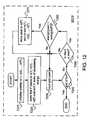
- FIGURE 13B shows a flowchart of a method M300 according to an embodiment.
- a bin culling procedure may include one or more of peak strength test task T500 and list energy distribution test task T600.
- Best maximum peak test T300 which selects the most likely valid maximum peak from among the surviving bins, may include tasks such as bin energy distribution test task T700, cross-correlation test task T800, and/or sidelobe test task T900.
- Best early peak test T400 which determines the presence of a more direct multipath related to the best maximum peak, also may include tasks such as bin energy distribution test task T700, cross-correlation test task T800, and/or sidelobe test task T900.
- the method returns a Doppler offset and/or a location in code phase that may be used to compute a pseudorange.
- L2 may be the value of the noise floor, or L2 may be the sum of the noise floor and a threshold T2 (where T2 may be equal to T1), or L2 may be a value that is calculated as a percentage (e.g. 110%) of the noise floor.
- Task T610 registers a pass if the energy of the (N + 1)-th peak is below the minimum value L2.
- FIGURE 14B shows an example of the pass and fail energy regions for an implementation of task T610.
- task T620 compares the difference between the energy values of the first and (N + 1)-th peaks in the bin list to a threshold T3. It may be desirable to select a value of T3 that is low enough to avoid separating peaks of a jammer ridge from one another, but high enough to prevent peaks from unrelated phenomena (such as an auto-correlation sidelobe) from being identified as valid and thus causing the bin to be discarded.
- the worst-case separation between an autocorrelation mainlobe and sidelobe for a GPS C/A code is 21.6 dB, and in one example, the value of T3 is set to 15 dB to allow a margin for variation and error.
- the bin has no more than N peaks above the noise level. If the (N + 1)-th peak is above the noise floor but more than a threshold value below the maximum peak, then it may be due to an auto-correlation sidelobe and thus be invalid, such that the bin still has no more than N valid peaks. In either case, the number of valid peaks in the bin is sufficiently limited to support the conclusion that the bin is not corrupted by a jammer. If the peak fails both tests (i.e. it is a valid peak), however, then the bin contains too many valid peaks and it is discarded. Tasks T610 and T620 may be performed in parallel or in either order, and either test may be skipped once the other has failed.
- one or both of tasks T610 and T620 may be configured according to an alternate logic.
- the tasks may be configured such that a peak above the noise floor passes test task T610, a peak within the threshold passes test task T620, and passing both tests indicates a valid peak.
- Another potential advantage of a list energy distribution test according to an implementation of task T600 is that such a test may exclude bins that have strong peaks due to cross-correlations with different codes. While a cross-correlation between two different GPS C/A codes will not produce a ridge like a jammer, nevertheless peaks caused by such a cross-correlation may be distinguished from those of a valid signal due to their periodicity in code space. Because of this periodicity, strong peaks due to such a cross-correlation may cause the number of valid peaks to exceed the maximum allowable number of multipaths N. The chances of excluding a cross-correlation bin as a jammer would increase as search window size increases in code phase (i.e. to include more periods of the cross-correlation function). Further embodiments include applying knowledge of which SVs are currently visible to identify the periods and/or Doppler frequencies of likely cross-correlations, determining whether peaks matching such criteria are present in the grid, and rejecting such peaks or their bins.
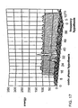
- a potential advantage of at least some implementations of a method as described herein is that even if several or many bins of the energy grid are corrupted by jammers, a valid peak in another bin can still be found. Even for a search window that is very large in code space, such that a jammer may cause a large number of energy peaks, a method according to an embodiment may be used to support rejecting the jammer peaks early in the processing cycle by removing the corrupted bins from consideration, while supporting subsequent identification of a valid peak by preserving a number of peaks for each of the other of d bins.
- FIGURE 17 shows one example of an early multipath that might thus be detected even in the presence of an overwhelmingly strong jammer ridge.
- a strong jamming signal may have other undesirable effects on a receiving device's operation.
- Receivers commonly include some form of automatic gain control (AGC) that increases amplifier gain when the received signal is weak and reduces the gain when the signal is strong (e.g. to keep the signal level within the dynamic range of the ADC(s)).
- a strong jamming signal may cause the AGC to reduce the gain enough to push a valid signal peak below the noise floor.
- a jammer may be the dominant source of in-band energy. While the AGC could be disabled or otherwise inhibited upon detection of such a jammer (e.g. during bin culling), increasing the signal level in this manner may cause the signal to become clipped.
- frequency bands corrupted by jammers are removed from the incoming signal.
- one or more bandstop filters may be selectably configured to attenuate an RF band in which a jammer has been detected. Such attenuation may be performed on the signal in the analog domain and/or digitally. In one implementation, a selectable attenuation is performed on a high-dynamic-range digital signal (e.g. 12 to 18 bits) before the signal is converted to a lower resolution (e.g. 4 bits) for further processing.
- a high-dynamic-range digital signal e.g. 12 to 18 bits
- a lower resolution e.g. 4 bits
- Bin energy distribution test task T700 processes a set of bin lists to identify a best maximum peak.
- FIGURE 18 shows a flowchart for an implementation T702 of task T700, which is configured to return the best maximum peak among the bin lists. This implementation, which includes one or more tests, iterates through a list of maximum peaks until a peak that passes the tests is found. Implementations of cross-correlation test task T800 and/or sidelobe test task T900 as described herein may be integrated into other implementations of task T700.
- Peak selection task T710 creates a list of maximum peaks from the bin lists by selecting the peak having the highest energy from each bin list (or from each surviving bin list, if bin culling has been performed). Task T710 may also sort the peaks in this list by their energy values (e.g. in decreasing order). In some applications, task T710 may be implemented to select and list more than one peak from one or more of the bins. Loop initialization task T720 selects the peak having the highest energy in the list as the current peak for testing.
- noise estimation task T730 obtains a measure of the average noise energy for the corresponding bin. This noise energy measure, which may be referred to as a mean measured noise estimate, may be calculated as the average energy of the non-peak samples of the bin.
- task T730 includes calculating the energy sum for the bin, subtracting the energy due to peaks, and dividing the resulting sum by the number of values in the bin less the number of subtracted values.
- the peaks to be subtracted may include only those peaks that appear in the bin list or may also include other local maxima that have an energy value above some threshold.
- the peaks to be subtracted include local maxima that are above the noise floor and within 15 dB of the maximum peak in the bin.
- Subtracting the energy due to peaks may also include subtracting the energy values of grid points in the bin that are adjacent to peaks, such that three values are subtracted from the bin for each peak.
- the average noise energy measure is calculated and provided by a searcher with the corresponding bin list.
- Ratio test task T740 compares the energy value for the current peak to the average noise energy for the bin. If the ratio between these values is less than (or equal to) a threshold T4, the peak is rejected. If the maximum peak in a bin fails this test, then all other peaks in the bin will fail as well and may be ignored.
- Threshold T4 may be fixed or variable.
- the value of T4 may be selected according to the period of coherent integration and/or the number of non-coherent integrations.
- the following table shows one example of a set of different values of T4: Coherent integration (milliseconds) Non-coherent integrations Total integration time (milliseconds) T4 (in dB) 20 4 80 16.832 20 44 880 13.718 80 22 1760 15.494
- the energy grid may also include peaks caused by cross-correlations between the reference code and other codes.
- the received signal may include codes transmitted by as many as twelve different SVs, and the energy grid may be expected to include peaks due to cross-correlations between the reference code and the codes of several of these SVs.
- the worst-case code separation between C/A codes is only 21.6 dB.
- Cross-correlation of the reference code with a code from another SV is most likely to present a problem when the signal from the SV being searched is highly attenuated relative to that of the other SV. Such a scenario may occur, for example, when the SV being searched is near the horizon, or blocked by an obstacle, while the other SV is within a line-of-sight.
- Signals from one or more pseudolites, synchrolites, or GPS repeaters may also cause a strong cross-correlation.
- the C/A codes have a period of one millisecond, the most significant cross-correlations occur when the difference between the interfering SV signal and the target SV signal is a multiple of 1 kHz.
- Information about the Doppler frequency offset of a potentially interfering SV signal may thus be used to determine the most likely location(s) of a cross-correlation with that signal in frequency space.
- Cross-correlation test task T800 compares the energy value and frequency hypothesis of a peak to parameters of a cross-correlation mask.
- FIGURE 19 shows a flowchart of an implementation T802 of cross-correlation task T800.
- Task T810 obtains a cross-correlation bin and threshold.
- Task T820 compares the bin of the current peak to the cross-correlation bin.
- Task T830 compares the energy value of the current peak to the cross-correlation threshold. If the peak falls within the mask, it is rejected as probably due to a cross-correlation with the signal of another visible SV.
- Task T802 may be iterated to test the peak against masks for one or more other SVs.
- task T810 may reference a lookup table that contains the identities and current Doppler locations of other visible SVs. This table may be based on information gained from past searches and/or obtained from another device such as a PDE.
- the Doppler difference between the location of the current peak and the location of the other SV is determined, and the modulo 1 kHz remainder of this value is calculated to indicate the cross-correlation, bin.
- Other mask parameters such as energy value threshold, mask width in Hertz or bins, and/or the modulo divider may be based on the energy value of the signal of the other SV and/or aspects of the current search such as bin spacing and coherent and/or noncoherent integration length. For a large Doppler difference between the peak and the other SV signal, a lower energy threshold may be used (e.g. due to code smearing at large Doppler offsets).
- task T800 may also be configured to test for compound cross-correlations arising from multiple sources (e.g. more than one other SV) with additive effect.
- multiple sources e.g. more than one other SV
- a discussion of other aspects that may be included in an implementation of cross-correlation task T800 is set forth in U.S. Patent Application Publication No. 2004/0196183 (Roh, published October 7, 2004 ), which discloses details such as masks for mainlobes, frequency sidelobes, and sample-and-hold cross-correlations (e.g. at paragraphs [0111]-[0161]).
- a best maximum peak selection process may be implemented such that when a cross-correlation test is performed, the selection process has already committed to that peak.
- cross-correlation test task T800 may be performed after task T760 or T780. If task T800 discards the peak as a cross-correlation, it may be too late to select another peak from the grid.
- a further implementation of a best maximum peak test task such as T702 includes a pre-emptive cross-correlation test task, which allows for an alternative candidate.
- the pre-emptive test task determines whether the current candidate for best maximum peak is from a suspect bin.
- the pre-emptive test task may reference a lookup table containing the Doppler offsets of other visible SVs as described above to calculate the locations of suspect bins. If the current candidate is from a suspect bin, then the pre-emptive test task tags the peak as a possible cross-correlation and the search for the best maximum peak continues.
- the pre-emptive test task may first determine whether the suspect bin contains more than a threshold number (e.g.
- the pre-emptive test task causes more than one candidate peak to be sent to cross-correlation test task T800, such that another candidate will be available if the first one is rejected.
- a method according to an embodiment may also include a sidelobe test task T900 (for example, within an implementation of best maximum peak test T300).
- Sidelobe test task T900 rejects candidate peaks that may be due to sidelobes of the current peak.
- One implementation of task T900 applies a mask which rejects peaks corresponding to code phases hat are later than or equal to 1 ⁇ 2 chip before that of the current peak (the time axis in the figure is marked in intervals of 1 ⁇ 2 chip), for rejection of frequency sidelobes (usually within one code hypothesis from the mainlobe) and all later peaks.
- Task T900 may apply such a mask to the same bin as the current peak, to a range including a few surrounding bins, or to all bins in the grid.
- the mask may also be configured to reject other unwanted peaks, such as peaks due to autocorrelation sidelobes.
- Sidelobes of a GPS C/A code autocorrelation function are 21.6 dB down from the mainlobe, and task T900 may apply a mask that is configured according to a threshold including a margin for variation and error.
- FIGURE 20 shows an example of such a mask which rejects peaks having energy values more than 15 dB below the current peak.
- Sidelobe test task T900 may also be implemented as a separate routine to cull peaks from a best maximum peak candidate list.
- a method according to a further embodiment includes a test for a peak due to an earlier multipath.
- Best early peak test task T400 searches one or more bin lists to identify peaks that are earlier than the best maximum peak.
- Task T400 may limit its search to peaks that correspond to code phase hypotheses up to a threshold of T6 chips earlier than that of the best maximum peak.
- the value of T6 is eight chips. As an error of one GPS chip corresponds to a distance of about 300 m, locating an earlier peak of a multipath signal may provide a significant increase in position location accuracy.
- the selected peak may be due to a cross-correlation with another code. Multipaths are most likely to occur indoors, where refraction and scattering are common. Thus, any change in Doppler due to relative movement between transmitter and receiver over the time span of the early peak search window is likely to be low anyway. Moreover, signals received indoors are also likely to be weak, and weak signal scenarios are susceptible to cross-correlations.
- peaks up to eight chips before the peak currently selected are considered as early peak candidates. It may also be desirable to exclude peaks within one-half chip from the peak currently selected (e.g. to avoid selecting a sidelobe).
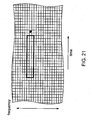
- FIGURE 21 shows one example of a mask that may be used in an early peak search, where the circle represents the peak currently selected (e.g. the best maximum peak) and the rectangle represents the mask measuring three frequency bins by eight chips (in this example, the resolution in code phase is one-half chip).
- the width of the mask in frequency space may depend on an expected range of Doppler change and/or refraction effects, and in other examples the mask extends two, three, four or more frequency bins on either side of the peak currently selected.
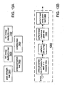
- FIGURE 22 shows a block diagram of an implementation 262 of a baseband processor 260 that may be configured to perform an implementation of method M100 as described herein.
- Processor 430 controls searcher 410 to obtain correlation results for a search window of C code phase and D frequency hypotheses and obtains sorted lists of peaks for each of d bins.
- Grid storage 420 may be used to store some or all of the correlation results (or energy results based on the correlation results).
- Grid storage 420 may also store instructions executed by processor 430 in performing the method.
- the sorted lists are provided to another processor for further processing (e.g. according to a best maximum peak test task and/or other tasks as described herein), although in another example, at least some further processing of the lists may be performed by processor 430.
- the various elements of baseband processor, 262 may be implemented on the same chip (possibly with other elements, such as portions of a device for communication with a network for cellular telephony) or may be distributed across different chips or even different devices.
- searcher 410 may be activated to process the received code as it is received, or may be activated to access the code from storage possibly at a later time, to obtain correlation and/or energy results.
- the results from searcher 410 may also be stored in an intermediate storage.
- Processor 430 may then be activated or interrupted from another task to process the results from searcher 410 to provide the sorted lists or further results, possibly storing this information in an intermediate storage to be accessed when another processor is activated or interrupted.
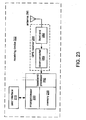
- FIGURE 23 shows a block diagram of an implementation of a receiving device 202 according to an embodiment.
- a receiving device 202 may be configured, for example, to be handheld, worn on the body (e.g. on a wristband), or vehicle-mounted.
- Such a device may also be configured to provide positional information, possibly in combination with Geographic Information Systems (GIS) information such as an enhanced map display.
- GIS Geographic Information Systems
- GIS Geographic Information Systems
- GPS receiver 280 is configured to receive and demodulate GPS satellite transmissions and provide the demodulated signal to a baseband processor 260.
- Baseband processor 260 is configured to derive correlation information from the demodulated signal. For a given reference code, baseband processor 260 produces a correlation function which is defined over a range of code phase hypotheses which define a search window W, and over a range of Doppler frequency hypotheses. Each individual correlation is performed in accordance with defined coherent and non-coherent integration parameters.
- An analog-to-digital converter converts the baseband signal from analog to a digital stream of samples.
- the ADC may oversample the baseband signal (at a rate of e.g. chipx2, chipx4, chipx8, chipx12, or chipx16 or within some range around such a rate).
- the ADC may also be configured to include two ADCs executing in parallel (e.g. each one receiving and digitizing a different respective component of a complex signal path of the downconverter).
- the ADC sampling clock may be derived from a local oscillator source such as a frequency reference signal.
- the sampling rate may be chosen depending on the desired search resolution in the code phase dimension and/or the desired bandwidth of the despread signal.
- Each component of the digital output may have a width of, for example, one, two, four, eight, or more bits.
- the ADC may be implemented as a comparator.
- the downconverter may also include an AGC stage upstream of one or more of the ADCs.
- a local oscillator signal is a periodic signal having a fundamental frequency that may be implemented to have any waveform suitable for the particular application (e.g. sinusoidal, square, triangular, sawtooth, etc.).
- One or more of the local oscillator signals may be obtained from a variable-frequency oscillator (VFO), which may be implemented as a crystal oscillator (or XO), a temperature-compensated oscillator (TCO), a temperature-compensated XO (TCXO), a voltage-controlled oscillator (VCO), a voltage-controlled TCO (VCTCO), or a voltage-controlled TCXO (VCTCXO).
- VFO variable-frequency oscillator
- TCO temperature-compensated oscillator
- TCXO temperature-compensated XO
- VCO voltage-controlled oscillator
- VCTCO voltage-controlled TCO
- VTCXO voltage-controlled TCXO
- a typical inexpensive TCXO has stability of about 1 ppm (part per
- One particular application includes a VCTCXO having a nominal output frequency of 19.68 MHz rated at +/- 5 ppm.
- a tolerance of +/- 5 ppm corresponds to a range of +/- 4 kHz out of 800 MHz, or +/- 9.5 kHz out of 1.9 GHz.
- One or more of the local oscillator signals applied in downconverter may be based on a frequency reference signal (for example, obtained from a VFO).
- downconverter 285 and/or device 202 may include one or more frequency synthesizers that use the frequency reference signal as a timing reference from which a signal of another frequency (e.g. a local oscillator signal) is derived.
- a synthesizer may be implemented, for example, as a frequency multiplier or divider and may include a circuit such as a phase-locked loop (PLL).
- PLL phase-locked loop
- a local oscillator signal may be supplied to a mixer of downconverter 322 as two components separated in phase by 90 degrees (e.g. I and Q), with each component being applied in a separate mixing path such that a complex downconverted signal is obtained.
- the amplitude of a local oscillator signal may be controlled, e.g. using a variable gain amplifier.
- the frequency reference signal (or a signal based on the frequency reference signal) may also be used as the sampling clock by which the ADC(s) sample the baseband (or near-baseband) signal.
- Baseband processor 260 may perform an implementation of method M100 to provide sorted lists to microprocessor 220 for further processing (e.g. according to a best maximum peak test task and/or other tasks as described herein), although in another example, at least some further processing of the lists may be performed by baseband processor 260.
- Microprocessor 220, memory 230, and baseband processor 262 may be implemented on the same chip or may be distributed across different chips or even different devices.
- Microprocessor 220 is configured to derive one or more time measurements (such as pseudoranges) from selected peaks. Microprocessor 220 may also be configured to determine an error (such as a root mean square error or RMSE) associated with a time measurement. Microprocessor 220 is configured to determine a location of device 202 based on selected peaks corresponding to several SVs.
- time measurements such as pseudoranges
- RMSE root mean square error
- Memory 230 may be configured to store instructions executed by baseband processor 260 and/or microprocessor 220 in performing a method as described or suggested herein. Memory 230 may also be configured to store instructions for other operations and/or to store intermediate results of such a method or operations. Microprocessor 220 may be configured to receive user commands and/or output results of such method and/or operations via user interface 210.
- User interface 210 comprises a plurality of devices for inputting user commands and/or outputting positional information such as coordinates on a map and/or in latitude, longitude, and/or altitude.
- User interface 210 may include such devices as a keypad and/or keyboard and a display screen (e.g. a liquid crystal or organic LED display).
- a receiving device may be integrated into a communications device.
- a communications device may include one tuner configured to switch between frequencies for different tasks.
- a signal sampled during a visit to the GPS frequency may be stored and processed after the tuner has tuned back to a communications (e.g. CDMA) frequency.
- a communications e.g. CDMA
- Requirements of the communications network and/or of a desired operating performance may limit the maximum available tune-away time.
- such a device may include more than one tuner.
- such a device may include a tuner dedicated to GPS reception and another tuner dedicated to other communications.
- FIGURE 25 shows a block diagram of an implementation 302 of a communications device according to an embodiment.
- a communications device may include the elements of receiving device 202 as shown in FIGURE 23 , with one of more of such elements possibly including additional features or being otherwise modified.
- Communications device 302 also includes a communications transceiver 270 including a front end 272 (which may be implemented as shown in FIGURE 24A and/or as discussed above), a downconverter 275 (which may be implemented as shown in FIGURE 24B or 24C and/or as discussed above), and a modulator 278 configured to modulate information such as voice or data onto an RF carrier for transmission via antenna 290.
- a communications transceiver 270 including a front end 272 (which may be implemented as shown in FIGURE 24A and/or as discussed above), a downconverter 275 (which may be implemented as shown in FIGURE 24B or 24C and/or as discussed above), and a modulator 278 configured to modulate information such as voice or data onto an RF carrier for
- Transceiver front end 272 is configured to receive a communications signal, such as a CDMA signal or other signal for communications with a network for cellular telephony, and may also include a duplexer to support receive and transmit activity over antenna 290.
- a communications signal such as a CDMA signal or other signal for communications with a network for cellular telephony
- duplexer to support receive and transmit activity over antenna 290.
- portions of a front end and/or downconverter may be common to the communications and GPS signal paths.
- baseband processor 260 is configured to provide baseband information from microprocessor 220 to transceiver 270 for transmission over a wireless communications link. Microprocessor 220 in turn obtains this baseband information from an input device within user interface 210. Baseband processor 260 is also configured to provide baseband information from transceiver 1206 to microprocessor 220. Microprocessor 220 in turn provides this baseband information to an output device within user interface 210.
- User interface 210 may be implemented to include one or more devices for inputting or outputting user information such as voice or data. Devices typically included within such a user interface include a keyboard, a display screen, a microphone, and a speaker.
- Baseband processor 260 may also be configured to derive pilot-related correlation functions from information relating to pilot signals provided to it by communications transceiver 270. This information may be used by communications device 302 to acquire wireless communications services.
- Memory 230 may be configured to store such instructions and/or intermediate results as are involved in executing communications operations of communications device 302.
- Information received via antenna 290 may include data to support modulation wipeoff, a listing of which SVs are currently visible and their approximate code phases and Dopplers, and a command to initiate an implementation of M100 or another method according to an embodiment.
- Microprocessor 220 may be configured to provide time measurements and errors to a PDE, which may be a network element such as a server connected to a computer network.
- the PDE weights each of the measurements based on the inverse of its corresponding RMSE value and estimates the position of communications device 302 based on the weighted measurements. The position calculated by the PDE may then be downloaded to device 302 so that it is available in case of a 911 or other emergency call.
- Other potential applications include user-requested location services, such as restaurant or ATM (automated teller machine) location, and push-oriented services such as position-dependent advertising. Communication between device 302 and a PDE may take place over at network for cellular communications.
- a device such as an implementation of receiving device 202 or communications device 302, may be an independents unit (possibly including other elements for e.g. power management, user interface support, further processing of information received from a GPS or other receiver) or a portion of a device or system that also includes other circuits and/or functionalities.
- a device may be included in a transceiver that also includes a transmitter, e.g. an access terminal such as a cellular telephone (configured to communicate with a system including a network of base stations and including e.g. a microphone, speaker, keypad, and associated circuits and processing) and/or a wireless modem (configured to support data transfer between a wireless channel and e.g.
- Such a transceiver may communicate with one or more processors for configuring operations in the device, processing signals within the device, and/or controlling a user interface of the device that may include input devices (e.g. a microphone, a keyboard or keypad) and/or output devices (e.g. a speaker or audio output jack, a display screen).
- input devices e.g. a microphone, a keyboard or keypad
- output devices e.g. a speaker or audio output jack, a display screen.
- Such a device may also be included in a device that supports further functionalities, e.g. including a media player (configured to decode audio information encoded into such compression formats as MP3, WMA, AAC3, and the like and/or video information encoded into such compression formats such as MPEG-2, MPEG-4, WMV, and the like), a personal digital assistant (PDA), a portable computer, etc.
- a media player configured to decode audio information encoded into such compression formats as MP3, WMA, AAC3, and the like and/or video information encoded into such compression formats such as MPEG-2, MPEG-4, WMV, and the like
- PDA personal digital assistant
- Such further functionalities may be integrated with the operations of a receiver and/or transmitter of the device: for example, playback of multimedia information received via the receiver; communication between applications executing locally (e.g. an e-mail client) and an external server via the wireless modem; synchronization of local and external schedules, contacts, or other databases via the wireless modem.
- Embodiments may be implemented in part or in whole as a hard-wired circuit or as a circuit configuration fabricated into an application-specific integrated circuit. Embodiments may also be implemented in part or in whole as a firmware program loaded into non-volatile storage, or a software program loaded from or into storage such as a data storage medium (e.g. one or more arrays of data storage elements such as semiconductor or magnetic random-access memory (volatile or nonvolatile, integrated or removable); magnetic, optical, or phase-change disc media; etc.), as machine-readable code.
- a data storage medium e.g. one or more arrays of data storage elements such as semiconductor or magnetic random-access memory (volatile or nonvolatile, integrated or removable); magnetic, optical, or phase-change disc media; etc.
Landscapes
- Engineering & Computer Science (AREA)
- Radar, Positioning & Navigation (AREA)
- Remote Sensing (AREA)
- Computer Networks & Wireless Communication (AREA)
- Physics & Mathematics (AREA)
- General Physics & Mathematics (AREA)
- Signal Processing (AREA)
- Position Fixing By Use Of Radio Waves (AREA)
- Telephonic Communication Services (AREA)
- Pharmaceuticals Containing Other Organic And Inorganic Compounds (AREA)
Priority Applications (1)
| Application Number | Priority Date | Filing Date | Title |
|---|---|---|---|
| EP11007819.3A EP2447736B1 (en) | 2004-12-01 | 2005-12-01 | Systems, methods, and apparatus for jammer rejection |
Applications Claiming Priority (2)
| Application Number | Priority Date | Filing Date | Title |
|---|---|---|---|
| US63251004P | 2004-12-01 | 2004-12-01 | |
| PCT/US2005/043529 WO2006060605A2 (en) | 2004-12-01 | 2005-12-01 | Systems, methods, and apparatus for jammer rejection |
Related Child Applications (4)
| Application Number | Title | Priority Date | Filing Date |
|---|---|---|---|
| EP11007819.3A Division EP2447736B1 (en) | 2004-12-01 | 2005-12-01 | Systems, methods, and apparatus for jammer rejection |
| EP11007821.9 Division-Into | 2011-09-26 | ||
| EP11007820.1 Division-Into | 2011-09-26 | ||
| EP11007819.3 Division-Into | 2011-09-26 |
Publications (2)
| Publication Number | Publication Date |
|---|---|
| EP1817605A2 EP1817605A2 (en) | 2007-08-15 |
| EP1817605B1 true EP1817605B1 (en) | 2012-01-18 |
Family
ID=36143643
Family Applications (2)
| Application Number | Title | Priority Date | Filing Date |
|---|---|---|---|
| EP05852691A Expired - Lifetime EP1817605B1 (en) | 2004-12-01 | 2005-12-01 | Systems, methods, and apparatus for jammer rejection |
| EP11007819.3A Expired - Lifetime EP2447736B1 (en) | 2004-12-01 | 2005-12-01 | Systems, methods, and apparatus for jammer rejection |
Family Applications After (1)
| Application Number | Title | Priority Date | Filing Date |
|---|---|---|---|
| EP11007819.3A Expired - Lifetime EP2447736B1 (en) | 2004-12-01 | 2005-12-01 | Systems, methods, and apparatus for jammer rejection |
Country Status (9)
| Country | Link |
|---|---|
| US (2) | US7764726B2 (enExample) |
| EP (2) | EP1817605B1 (enExample) |
| JP (3) | JP2008522558A (enExample) |
| KR (2) | KR100916731B1 (enExample) |
| CN (2) | CN101103279B (enExample) |
| AT (1) | ATE542152T1 (enExample) |
| AU (1) | AU2005311807A1 (enExample) |
| IL (1) | IL183439A0 (enExample) |
| WO (1) | WO2006060605A2 (enExample) |
Cited By (1)
| Publication number | Priority date | Publication date | Assignee | Title |
|---|---|---|---|---|
| CN103064090A (zh) * | 2012-12-26 | 2013-04-24 | 电子科技大学 | 一种抗干扰方法 |
Families Citing this family (80)
| Publication number | Priority date | Publication date | Assignee | Title |
|---|---|---|---|---|
| US9026070B2 (en) * | 2003-12-18 | 2015-05-05 | Qualcomm Incorporated | Low-power wireless diversity receiver with multiple receive paths |
| JP2006067284A (ja) * | 2004-08-27 | 2006-03-09 | Matsushita Electric Ind Co Ltd | 高周波受信装置とこれを用いた携帯機器 |
| EP1894310A1 (en) * | 2005-06-24 | 2008-03-05 | Thomson Licensing | Multipath searcher results sorting method |
| US8611305B2 (en) | 2005-08-22 | 2013-12-17 | Qualcomm Incorporated | Interference cancellation for wireless communications |
| US9071344B2 (en) | 2005-08-22 | 2015-06-30 | Qualcomm Incorporated | Reverse link interference cancellation |
| US9450665B2 (en) * | 2005-10-19 | 2016-09-20 | Qualcomm Incorporated | Diversity receiver for wireless communication |
| US7899107B1 (en) | 2006-04-17 | 2011-03-01 | Marvell International Ltd. | Preamble detection using low-complexity cross-correlation |
| US7864898B2 (en) * | 2006-05-17 | 2011-01-04 | Sirf Technology Holdings, Inc. | Systems and methods for signal acquistion in navigational satellite signal receivers |
| US7991077B1 (en) | 2006-05-31 | 2011-08-02 | Marvell International Ltd. | Preamble detection with multiple receive antennas |
| US8121238B2 (en) | 2006-06-30 | 2012-02-21 | Csr Technology Inc. | System and method for synchronizing digital bits in a data stream |
| US7605751B2 (en) * | 2006-09-14 | 2009-10-20 | Honeywell International Inc. | Global navigation satellite system repeater disruption monitoring |
| EP1916535B1 (en) * | 2006-10-26 | 2015-11-18 | Qualcomm Incorporated | GNSS receiver with cross-correlation rejection |
| US7986922B2 (en) * | 2006-12-15 | 2011-07-26 | Qualcomm Incorporated | Jammer detection and suppression for wireless communication |
| WO2008105700A1 (en) * | 2007-02-26 | 2008-09-04 | Telefonaktiebolaget Lm Ericsson (Publ) | Apparatuses and a method for reducing peak power in a transmitter of telecommunications systems |
| CN103698787B (zh) * | 2007-11-15 | 2016-05-18 | 高通股份有限公司 | Gnss接收器以及信号跟踪电路和系统 |
| JP5499435B2 (ja) | 2007-11-20 | 2014-05-21 | セイコーエプソン株式会社 | 相互相関判定方法、測位装置及び電子機器 |
| US20090153397A1 (en) * | 2007-12-14 | 2009-06-18 | Mediatek Inc. | Gnss satellite signal interference handling method and correlator implementing the same |
| US20090196378A1 (en) * | 2008-01-31 | 2009-08-06 | Mediatek Inc. | Post correlation system for gnss receiver |
| US8599905B2 (en) * | 2008-02-22 | 2013-12-03 | Freescale Semiconductor, Inc. | Processor for use as a path searcher of a spread spectrum receiver and a method of operation of the processor |
| US8094702B2 (en) * | 2008-04-28 | 2012-01-10 | Qualcomm Incorporated | System and/or method for detecting multi-tone jamming |
| TWI389030B (zh) | 2008-05-07 | 2013-03-11 | Mstar Semiconductor Inc | 於微處理器下載並執行程式碼的方法與電腦程式產品以及包含該微處理器之通訊裝置 |
| US20100046660A1 (en) | 2008-05-13 | 2010-02-25 | Qualcomm Incorporated | Interference cancellation under non-stationary conditions |
| US8081922B2 (en) * | 2008-05-30 | 2011-12-20 | Qualcomm Incorporated | Methods and apparatuses for processing satellite positioning system signals |
| TWI378253B (en) * | 2008-06-06 | 2012-12-01 | Mstar Semiconductor Inc | Mixed gps receiving method and associated device and system |
| US9408165B2 (en) | 2008-06-09 | 2016-08-02 | Qualcomm Incorporated | Increasing capacity in wireless communications |
| US8442095B2 (en) * | 2008-06-14 | 2013-05-14 | Qualcomm Incorporated | Multiple correlation processing in code space search |
| CN101614806B (zh) * | 2008-06-23 | 2015-03-11 | 晨星软件研发(深圳)有限公司 | 混合型全球定位系统接收方法、接收装置及系统 |
| CN101349740B (zh) * | 2008-07-29 | 2011-09-07 | 北京航空航天大学 | 通用卫星导航信号干扰源及其信号产生方法 |
| US9277487B2 (en) * | 2008-08-01 | 2016-03-01 | Qualcomm Incorporated | Cell detection with interference cancellation |
| US9237515B2 (en) | 2008-08-01 | 2016-01-12 | Qualcomm Incorporated | Successive detection and cancellation for cell pilot detection |
| US8503591B2 (en) * | 2008-08-19 | 2013-08-06 | Qualcomm Incorporated | Enhanced geran receiver using channel input beamforming |
| US8193987B2 (en) * | 2008-08-25 | 2012-06-05 | DRS Soneticom. Inc. | Apparatus and method for determining signal quality in a geolocation system |
| US20100117884A1 (en) * | 2008-11-11 | 2010-05-13 | Qualcomm Incorporated | Method for performing consistency checks for multiple signals received from a transmitter |
| FR2943477A1 (fr) * | 2009-03-17 | 2010-09-24 | Thales Sa | Dispositif de pilotage en frequence pour emetteur/recepteur de telecommande satellite,emetteur recepteur associes |
| US9160577B2 (en) * | 2009-04-30 | 2015-10-13 | Qualcomm Incorporated | Hybrid SAIC receiver |
| US8787509B2 (en) | 2009-06-04 | 2014-07-22 | Qualcomm Incorporated | Iterative interference cancellation receiver |
| US8362951B2 (en) * | 2009-07-02 | 2013-01-29 | Qualcomm Incorporated | Carrier phase processing in discontinuous satellite positioning system tracking |
| US8369279B2 (en) | 2010-03-10 | 2013-02-05 | Broadcom Corporation | Method and system for iterative multiple frequency hypothesis testing with cell-ID detection in an E-UTRA/LTE UE receiver |
| US8462647B2 (en) * | 2009-07-28 | 2013-06-11 | Broadcom Corporation | Method and system for multiple frequency hypothesis testing with full synch acquisition in an E-UTRA/LTE UE receiver |
| JP5368213B2 (ja) * | 2009-08-20 | 2013-12-18 | 日本無線株式会社 | Gnss受信機 |
| US8831149B2 (en) | 2009-09-03 | 2014-09-09 | Qualcomm Incorporated | Symbol estimation methods and apparatuses |
| US8619928B2 (en) * | 2009-09-03 | 2013-12-31 | Qualcomm Incorporated | Multi-stage interference suppression |
| KR101363016B1 (ko) | 2009-11-27 | 2014-02-13 | 퀄컴 인코포레이티드 | 무선 통신들에서의 용량 증가 |
| EP2505011B1 (en) | 2009-11-27 | 2019-01-16 | Qualcomm Incorporated | Increasing capacity in wireless communications |
| JP5483750B2 (ja) * | 2009-11-30 | 2014-05-07 | 古野電気株式会社 | 不要信号判別装置、不要信号判別方法、不要信号判別プログラム、gnss受信装置および移動端末 |
| US8433991B2 (en) * | 2010-06-16 | 2013-04-30 | Qualcomm Incorporated | Global Navigation Satellite System (GLONASS) data bit edge detection |
| US8427366B2 (en) | 2010-07-27 | 2013-04-23 | Texas Instruments Incorporated | Dual frequency receiver with single I/Q IF pair and mixer |
| KR101040261B1 (ko) | 2010-08-27 | 2011-06-10 | 엘아이지넥스원 주식회사 | 비행체의 고도 측정 장치 및 방법 |
| US8780958B2 (en) | 2010-08-27 | 2014-07-15 | Qualcomm Incorporated | Hybrid bit extraction for global position receiver |
| US8619919B2 (en) | 2010-10-14 | 2013-12-31 | Qualcomm Incorporated | Selective coherent and non-coherent demodulation methods and apparatuses |
| US9178669B2 (en) | 2011-05-17 | 2015-11-03 | Qualcomm Incorporated | Non-adjacent carrier aggregation architecture |
| US9252827B2 (en) | 2011-06-27 | 2016-02-02 | Qualcomm Incorporated | Signal splitting carrier aggregation receiver architecture |
| US9154179B2 (en) | 2011-06-29 | 2015-10-06 | Qualcomm Incorporated | Receiver with bypass mode for improved sensitivity |
| US12081243B2 (en) | 2011-08-16 | 2024-09-03 | Qualcomm Incorporated | Low noise amplifiers with combined outputs |
| US8774334B2 (en) | 2011-11-09 | 2014-07-08 | Qualcomm Incorporated | Dynamic receiver switching |
| KR101356239B1 (ko) * | 2012-01-30 | 2014-02-05 | 한국과학기술원 | Gnss 및 대역확산 신호의 신속한 신호 획득을 위한 압축 감지 방법 및 그 장치 |
| WO2013115481A1 (ko) * | 2012-01-30 | 2013-08-08 | 한국과학기술원 | 지엔에스에스 및 대역확산 신호의 신속한 신호 획득을 위한 압축 감지 방법 및 그 장치 |
| US9362958B2 (en) | 2012-03-02 | 2016-06-07 | Qualcomm Incorporated | Single chip signal splitting carrier aggregation receiver architecture |
| US9172402B2 (en) | 2012-03-02 | 2015-10-27 | Qualcomm Incorporated | Multiple-input and multiple-output carrier aggregation receiver reuse architecture |
| US8559483B1 (en) * | 2012-03-29 | 2013-10-15 | Nxp B.V. | Signal quality monitor |
| US9118439B2 (en) | 2012-04-06 | 2015-08-25 | Qualcomm Incorporated | Receiver for imbalanced carriers |
| US9154356B2 (en) | 2012-05-25 | 2015-10-06 | Qualcomm Incorporated | Low noise amplifiers for carrier aggregation |
| US9867194B2 (en) | 2012-06-12 | 2018-01-09 | Qualcomm Incorporated | Dynamic UE scheduling with shared antenna and carrier aggregation |
| US9300420B2 (en) | 2012-09-11 | 2016-03-29 | Qualcomm Incorporated | Carrier aggregation receiver architecture |
| US8958511B2 (en) * | 2012-09-27 | 2015-02-17 | Electronics And Telecommunications Research Institute | System and method for detecting broadband global positioning system (GPS) jamming |
| US9543903B2 (en) | 2012-10-22 | 2017-01-10 | Qualcomm Incorporated | Amplifiers with noise splitting |
| US8995591B2 (en) | 2013-03-14 | 2015-03-31 | Qualcomm, Incorporated | Reusing a single-chip carrier aggregation receiver to support non-cellular diversity |
| US9897701B2 (en) | 2013-10-08 | 2018-02-20 | Samsung Electronics Co., Ltd | Method for efficiently detecting impairments in a multi-constellation GNSS receiver |
| WO2017052510A1 (en) | 2015-09-22 | 2017-03-30 | Halliburton Energy Services, Inc. | Wellbore isolation device with slip assembly |
| US10177722B2 (en) | 2016-01-12 | 2019-01-08 | Qualcomm Incorporated | Carrier aggregation low-noise amplifier with tunable integrated power splitter |
| EP3435114B1 (de) * | 2017-07-28 | 2021-09-08 | Elmos Semiconductor SE | Verfahren zur übertragung von ultraschallmesssignale repräsentierenden daten insbesondere in einem fahrzeug |
| EP3502745B1 (en) * | 2017-12-20 | 2020-07-15 | Centre National d'Etudes Spatiales | Receiver-independent spoofing detection device |
| GB2580304B (en) * | 2018-11-20 | 2022-09-21 | Imagination Tech Ltd | GNSS receiver |
| GB2580302B (en) * | 2018-11-20 | 2022-10-26 | Imagination Tech Ltd | GNSS Receiver |
| CN109709581B (zh) * | 2019-02-27 | 2020-06-12 | 中国电子科技集团公司第五十四研究所 | 一种卫星导航信号强干扰循环特征参数快速检测获取方法 |
| CN110879380B (zh) * | 2019-08-19 | 2022-03-22 | 中国电波传播研究所(中国电子科技集团公司第二十二研究所) | 一种基于手机的gnss干扰源定位方法 |
| CN110971251A (zh) * | 2019-12-25 | 2020-04-07 | 中电科航空电子有限公司 | 机载电磁波设备、及抗干扰系统、方法及装置 |
| US11811440B2 (en) * | 2021-05-21 | 2023-11-07 | Rockwell Collins, Inc. | System and method for cancelation of internally generated spurious signals in a broadband radio receiver |
| CN114325600B (zh) * | 2021-12-22 | 2023-09-26 | 广东邦盛北斗科技股份公司 | 用于北斗导航系统的抗干扰方法、系统、装置及云平台 |
| EP4612812A1 (en) * | 2022-10-31 | 2025-09-10 | Telefonaktiebolaget LM Ericsson (publ) | User equipment assisted jamming detection |
Citations (1)
| Publication number | Priority date | Publication date | Assignee | Title |
|---|---|---|---|---|
| US20040042568A1 (en) * | 2002-08-29 | 2004-03-04 | Rowitch Douglas N. | Procedure for jammer detection |
Family Cites Families (25)
| Publication number | Priority date | Publication date | Assignee | Title |
|---|---|---|---|---|
| US4701934A (en) | 1985-09-03 | 1987-10-20 | Motorola, Inc. | Method of doppler searching in a digital GPS receiver |
| JPH06252887A (ja) * | 1993-03-01 | 1994-09-09 | Toyo Commun Equip Co Ltd | スペクトラム拡散信号復調装置 |
| US6633255B2 (en) | 1995-10-09 | 2003-10-14 | Qualcomm Inc. | Method for open loop tracking GPS signals |
| US5663734A (en) | 1995-10-09 | 1997-09-02 | Precision Tracking, Inc. | GPS receiver and method for processing GPS signals |
| JP3793632B2 (ja) * | 1997-12-18 | 2006-07-05 | 松下電器産業株式会社 | セルサーチ方法及び移動局装置 |
| US6366599B1 (en) | 1998-03-16 | 2002-04-02 | Trimble Navigation Limited | Fast acquisition of spread-spectrum signals by dynamically varying spacing of search bins |
| US6448925B1 (en) * | 1999-02-04 | 2002-09-10 | Conexant Systems, Inc. | Jamming detection and blanking for GPS receivers |
| US6477196B1 (en) * | 1999-08-30 | 2002-11-05 | Rockwell Collins, Inc. | Direct sequence spread spectrum communications receiver and method for efficient narrow-band signal excision |
| FI19992653A7 (fi) * | 1999-12-09 | 2001-06-10 | Nokia Mobile Phones Ltd | Menetelmä vastaanottimen tahdistamiseksi ja vastaanotin |
| FI112893B (fi) * | 1999-12-21 | 2004-01-30 | Nokia Corp | Menetelmä vastaanottimessa ja vastaanotin |
| JP2004509358A (ja) | 2000-09-18 | 2004-03-25 | スカイビッツ,インコーポレイテッド | Gps受信機におけるコード位相ならびにキャリア周波数の高速捕捉システム並びに方法 |
| JP2002122653A (ja) * | 2000-10-13 | 2002-04-26 | Matsushita Electric Works Ltd | 分散型gps受信システム用端末器 |
| US6700922B2 (en) | 2001-04-09 | 2004-03-02 | Raghu Challa | System and method for acquiring a received signal in a spread spectrum device |
| US7069019B2 (en) * | 2001-09-08 | 2006-06-27 | Sirf Technology, Inc. | System and method to estimate the location of a receiver |
| US7308022B2 (en) | 2001-11-01 | 2007-12-11 | Rick Roland R | Parameter estimator configured to distinguish between peaks and sidelobes of correlation function |
| US7738533B2 (en) | 2002-01-07 | 2010-06-15 | Qualcomm Incorporated | Multiplexed CDMA and GPS searching |
| JP2003232844A (ja) * | 2002-02-08 | 2003-08-22 | Sony Corp | 受信装置 |
| JP2003258681A (ja) * | 2002-02-28 | 2003-09-12 | Sony Corp | マッチドフィルタ装置及び相関検出方法並びに受信装置 |
| WO2004005954A2 (en) | 2002-07-10 | 2004-01-15 | Qualcomm, Incorporated | Cross-correlation mitigation method and apparatus for use in a global positioning system receiver |
| US7657230B2 (en) * | 2002-08-29 | 2010-02-02 | Qualcomm Incorporated | Procedure for detecting interfering multi-path condition |
| CA2506700C (en) * | 2002-10-04 | 2013-05-21 | Sigtec Navigation Pty Ltd | Satellite-based positioning system improvement |
| US6873910B2 (en) | 2002-10-22 | 2005-03-29 | Qualcomm Incorporated | Procedure for searching for position determination signals using a plurality of search modes |
| WO2004038945A1 (en) | 2002-10-24 | 2004-05-06 | Nokia Corporation | Determination of the code phase between a code modulated signal and a replica code sequence |
| CN1474196A (zh) * | 2003-05-15 | 2004-02-11 | 重庆赛洛克无线定位有限公司 | 无线定位中高精度、抗多径的窄带相关测距系统 |
| JP2005201814A (ja) * | 2004-01-16 | 2005-07-28 | Kanazawa Univ Tlo Inc | スペクトル拡散方式の受信機および受信信号処理方法 |
-
2005
- 2005-11-30 US US11/291,173 patent/US7764726B2/en active Active
- 2005-12-01 KR KR1020077015103A patent/KR100916731B1/ko not_active Expired - Fee Related
- 2005-12-01 CN CN2005800468909A patent/CN101103279B/zh not_active Expired - Fee Related
- 2005-12-01 AU AU2005311807A patent/AU2005311807A1/en not_active Abandoned
- 2005-12-01 JP JP2007544520A patent/JP2008522558A/ja not_active Withdrawn
- 2005-12-01 EP EP05852691A patent/EP1817605B1/en not_active Expired - Lifetime
- 2005-12-01 EP EP11007819.3A patent/EP2447736B1/en not_active Expired - Lifetime
- 2005-12-01 KR KR1020097003431A patent/KR101022995B1/ko not_active Expired - Fee Related
- 2005-12-01 CN CN201210053563.8A patent/CN102608623B/zh not_active Expired - Fee Related
- 2005-12-01 WO PCT/US2005/043529 patent/WO2006060605A2/en not_active Ceased
- 2005-12-01 AT AT05852691T patent/ATE542152T1/de active
-
2007
- 2007-05-27 IL IL183439A patent/IL183439A0/en unknown
-
2010
- 2010-07-26 US US12/843,605 patent/US8213487B2/en not_active Expired - Fee Related
- 2010-09-16 JP JP2010208038A patent/JP5456630B2/ja not_active Expired - Fee Related
-
2011
- 2011-08-25 JP JP2011183364A patent/JP5631823B2/ja not_active Expired - Fee Related
Patent Citations (1)
| Publication number | Priority date | Publication date | Assignee | Title |
|---|---|---|---|---|
| US20040042568A1 (en) * | 2002-08-29 | 2004-03-04 | Rowitch Douglas N. | Procedure for jammer detection |
Cited By (1)
| Publication number | Priority date | Publication date | Assignee | Title |
|---|---|---|---|---|
| CN103064090A (zh) * | 2012-12-26 | 2013-04-24 | 电子科技大学 | 一种抗干扰方法 |
Also Published As
| Publication number | Publication date |
|---|---|
| WO2006060605A3 (en) | 2006-11-09 |
| CN102608623B (zh) | 2014-06-04 |
| EP1817605A2 (en) | 2007-08-15 |
| ATE542152T1 (de) | 2012-02-15 |
| US8213487B2 (en) | 2012-07-03 |
| JP5631823B2 (ja) | 2014-11-26 |
| JP2008522558A (ja) | 2008-06-26 |
| CN101103279A (zh) | 2008-01-09 |
| CN101103279B (zh) | 2012-05-16 |
| IL183439A0 (en) | 2007-09-20 |
| JP2011050060A (ja) | 2011-03-10 |
| EP2447736A3 (en) | 2013-01-30 |
| US20100316095A1 (en) | 2010-12-16 |
| EP2447736B1 (en) | 2017-01-18 |
| US20060222058A1 (en) | 2006-10-05 |
| WO2006060605A2 (en) | 2006-06-08 |
| AU2005311807A1 (en) | 2006-06-08 |
| KR100916731B1 (ko) | 2009-09-14 |
| KR20070086870A (ko) | 2007-08-27 |
| CN102608623A (zh) | 2012-07-25 |
| JP5456630B2 (ja) | 2014-04-02 |
| US7764726B2 (en) | 2010-07-27 |
| KR20090033901A (ko) | 2009-04-06 |
| JP2012042474A (ja) | 2012-03-01 |
| KR101022995B1 (ko) | 2011-03-22 |
| EP2447736A2 (en) | 2012-05-02 |
Similar Documents
| Publication | Publication Date | Title |
|---|---|---|
| EP1817605B1 (en) | Systems, methods, and apparatus for jammer rejection | |
| EP2288931B1 (en) | System and/or method for detecting multi-tone jamming | |
| US8442095B2 (en) | Multiple correlation processing in code space search | |
| US20110273332A1 (en) | Method for processing combined navigation signals | |
| EP2446302B1 (en) | Wideband correlation mode switching methods and apparatuses | |
| HK1109932A (en) | Systems, methods, and apparatus for jammer rejection |
Legal Events
| Date | Code | Title | Description |
|---|---|---|---|
| PUAI | Public reference made under article 153(3) epc to a published international application that has entered the european phase |
Free format text: ORIGINAL CODE: 0009012 |
|
| 17P | Request for examination filed |
Effective date: 20070531 |
|
| AK | Designated contracting states |
Kind code of ref document: A2 Designated state(s): AT BE BG CH CY CZ DE DK EE ES FI FR GB GR HU IE IS IT LI LT LU LV MC NL PL PT RO SE SI SK TR |
|
| DAX | Request for extension of the european patent (deleted) | ||
| 17Q | First examination report despatched |
Effective date: 20090916 |
|
| REG | Reference to a national code |
Ref country code: DE Ref legal event code: R079 Ref document number: 602005032336 Country of ref document: DE Free format text: PREVIOUS MAIN CLASS: G01S0001000000 Ipc: G01S0019210000 |
|
| GRAP | Despatch of communication of intention to grant a patent |
Free format text: ORIGINAL CODE: EPIDOSNIGR1 |
|
| RIC1 | Information provided on ipc code assigned before grant |
Ipc: H04B 1/7097 20110101ALI20110715BHEP Ipc: G01S 19/21 20100101AFI20110715BHEP |
|
| GRAS | Grant fee paid |
Free format text: ORIGINAL CODE: EPIDOSNIGR3 |
|
| GRAA | (expected) grant |
Free format text: ORIGINAL CODE: 0009210 |
|
| AK | Designated contracting states |
Kind code of ref document: B1 Designated state(s): AT BE BG CH CY CZ DE DK EE ES FI FR GB GR HU IE IS IT LI LT LU LV MC NL PL PT RO SE SI SK TR |
|
| REG | Reference to a national code |
Ref country code: GB Ref legal event code: FG4D |
|
| REG | Reference to a national code |
Ref country code: CH Ref legal event code: EP |
|
| REG | Reference to a national code |
Ref country code: IE Ref legal event code: FG4D Ref country code: AT Ref legal event code: REF Ref document number: 542152 Country of ref document: AT Kind code of ref document: T Effective date: 20120215 |
|
| REG | Reference to a national code |
Ref country code: DE Ref legal event code: R096 Ref document number: 602005032336 Country of ref document: DE Effective date: 20120315 |
|
| REG | Reference to a national code |
Ref country code: NL Ref legal event code: VDEP Effective date: 20120118 |
|
| LTIE | Lt: invalidation of european patent or patent extension |
Effective date: 20120118 |
|
| PG25 | Lapsed in a contracting state [announced via postgrant information from national office to epo] |
Ref country code: IS Free format text: LAPSE BECAUSE OF FAILURE TO SUBMIT A TRANSLATION OF THE DESCRIPTION OR TO PAY THE FEE WITHIN THE PRESCRIBED TIME-LIMIT Effective date: 20120518 Ref country code: BE Free format text: LAPSE BECAUSE OF FAILURE TO SUBMIT A TRANSLATION OF THE DESCRIPTION OR TO PAY THE FEE WITHIN THE PRESCRIBED TIME-LIMIT Effective date: 20120118 Ref country code: LT Free format text: LAPSE BECAUSE OF FAILURE TO SUBMIT A TRANSLATION OF THE DESCRIPTION OR TO PAY THE FEE WITHIN THE PRESCRIBED TIME-LIMIT Effective date: 20120118 Ref country code: BG Free format text: LAPSE BECAUSE OF FAILURE TO SUBMIT A TRANSLATION OF THE DESCRIPTION OR TO PAY THE FEE WITHIN THE PRESCRIBED TIME-LIMIT Effective date: 20120418 Ref country code: NL Free format text: LAPSE BECAUSE OF FAILURE TO SUBMIT A TRANSLATION OF THE DESCRIPTION OR TO PAY THE FEE WITHIN THE PRESCRIBED TIME-LIMIT Effective date: 20120118 |
|
| PG25 | Lapsed in a contracting state [announced via postgrant information from national office to epo] |
Ref country code: PT Free format text: LAPSE BECAUSE OF FAILURE TO SUBMIT A TRANSLATION OF THE DESCRIPTION OR TO PAY THE FEE WITHIN THE PRESCRIBED TIME-LIMIT Effective date: 20120518 Ref country code: GR Free format text: LAPSE BECAUSE OF FAILURE TO SUBMIT A TRANSLATION OF THE DESCRIPTION OR TO PAY THE FEE WITHIN THE PRESCRIBED TIME-LIMIT Effective date: 20120419 Ref country code: FI Free format text: LAPSE BECAUSE OF FAILURE TO SUBMIT A TRANSLATION OF THE DESCRIPTION OR TO PAY THE FEE WITHIN THE PRESCRIBED TIME-LIMIT Effective date: 20120118 Ref country code: LV Free format text: LAPSE BECAUSE OF FAILURE TO SUBMIT A TRANSLATION OF THE DESCRIPTION OR TO PAY THE FEE WITHIN THE PRESCRIBED TIME-LIMIT Effective date: 20120118 Ref country code: PL Free format text: LAPSE BECAUSE OF FAILURE TO SUBMIT A TRANSLATION OF THE DESCRIPTION OR TO PAY THE FEE WITHIN THE PRESCRIBED TIME-LIMIT Effective date: 20120118 |
|
| REG | Reference to a national code |
Ref country code: AT Ref legal event code: MK05 Ref document number: 542152 Country of ref document: AT Kind code of ref document: T Effective date: 20120118 |
|
| PG25 | Lapsed in a contracting state [announced via postgrant information from national office to epo] |
Ref country code: CY Free format text: LAPSE BECAUSE OF FAILURE TO SUBMIT A TRANSLATION OF THE DESCRIPTION OR TO PAY THE FEE WITHIN THE PRESCRIBED TIME-LIMIT Effective date: 20120118 |
|
| PG25 | Lapsed in a contracting state [announced via postgrant information from national office to epo] |
Ref country code: SE Free format text: LAPSE BECAUSE OF FAILURE TO SUBMIT A TRANSLATION OF THE DESCRIPTION OR TO PAY THE FEE WITHIN THE PRESCRIBED TIME-LIMIT Effective date: 20120118 Ref country code: CZ Free format text: LAPSE BECAUSE OF FAILURE TO SUBMIT A TRANSLATION OF THE DESCRIPTION OR TO PAY THE FEE WITHIN THE PRESCRIBED TIME-LIMIT Effective date: 20120118 Ref country code: SI Free format text: LAPSE BECAUSE OF FAILURE TO SUBMIT A TRANSLATION OF THE DESCRIPTION OR TO PAY THE FEE WITHIN THE PRESCRIBED TIME-LIMIT Effective date: 20120118 Ref country code: DK Free format text: LAPSE BECAUSE OF FAILURE TO SUBMIT A TRANSLATION OF THE DESCRIPTION OR TO PAY THE FEE WITHIN THE PRESCRIBED TIME-LIMIT Effective date: 20120118 Ref country code: EE Free format text: LAPSE BECAUSE OF FAILURE TO SUBMIT A TRANSLATION OF THE DESCRIPTION OR TO PAY THE FEE WITHIN THE PRESCRIBED TIME-LIMIT Effective date: 20120118 Ref country code: RO Free format text: LAPSE BECAUSE OF FAILURE TO SUBMIT A TRANSLATION OF THE DESCRIPTION OR TO PAY THE FEE WITHIN THE PRESCRIBED TIME-LIMIT Effective date: 20120118 |
|
| PLBE | No opposition filed within time limit |
Free format text: ORIGINAL CODE: 0009261 |
|
| STAA | Information on the status of an ep patent application or granted ep patent |
Free format text: STATUS: NO OPPOSITION FILED WITHIN TIME LIMIT |
|
| PG25 | Lapsed in a contracting state [announced via postgrant information from national office to epo] |
Ref country code: IT Free format text: LAPSE BECAUSE OF FAILURE TO SUBMIT A TRANSLATION OF THE DESCRIPTION OR TO PAY THE FEE WITHIN THE PRESCRIBED TIME-LIMIT Effective date: 20120118 Ref country code: SK Free format text: LAPSE BECAUSE OF FAILURE TO SUBMIT A TRANSLATION OF THE DESCRIPTION OR TO PAY THE FEE WITHIN THE PRESCRIBED TIME-LIMIT Effective date: 20120118 |
|
| 26N | No opposition filed |
Effective date: 20121019 |
|
| PG25 | Lapsed in a contracting state [announced via postgrant information from national office to epo] |
Ref country code: AT Free format text: LAPSE BECAUSE OF FAILURE TO SUBMIT A TRANSLATION OF THE DESCRIPTION OR TO PAY THE FEE WITHIN THE PRESCRIBED TIME-LIMIT Effective date: 20120118 |
|
| REG | Reference to a national code |
Ref country code: DE Ref legal event code: R097 Ref document number: 602005032336 Country of ref document: DE Effective date: 20121019 |
|
| PG25 | Lapsed in a contracting state [announced via postgrant information from national office to epo] |
Ref country code: ES Free format text: LAPSE BECAUSE OF FAILURE TO SUBMIT A TRANSLATION OF THE DESCRIPTION OR TO PAY THE FEE WITHIN THE PRESCRIBED TIME-LIMIT Effective date: 20120429 |
|
| PG25 | Lapsed in a contracting state [announced via postgrant information from national office to epo] |
Ref country code: MC Free format text: LAPSE BECAUSE OF NON-PAYMENT OF DUE FEES Effective date: 20121231 |
|
| REG | Reference to a national code |
Ref country code: CH Ref legal event code: PL |
|
| REG | Reference to a national code |
Ref country code: IE Ref legal event code: MM4A |
|
| REG | Reference to a national code |
Ref country code: FR Ref legal event code: ST Effective date: 20130830 |
|
| PG25 | Lapsed in a contracting state [announced via postgrant information from national office to epo] |
Ref country code: IE Free format text: LAPSE BECAUSE OF NON-PAYMENT OF DUE FEES Effective date: 20121201 Ref country code: CH Free format text: LAPSE BECAUSE OF NON-PAYMENT OF DUE FEES Effective date: 20121231 Ref country code: LI Free format text: LAPSE BECAUSE OF NON-PAYMENT OF DUE FEES Effective date: 20121231 |
|
| PG25 | Lapsed in a contracting state [announced via postgrant information from national office to epo] |
Ref country code: FR Free format text: LAPSE BECAUSE OF NON-PAYMENT OF DUE FEES Effective date: 20130102 |
|
| PG25 | Lapsed in a contracting state [announced via postgrant information from national office to epo] |
Ref country code: TR Free format text: LAPSE BECAUSE OF FAILURE TO SUBMIT A TRANSLATION OF THE DESCRIPTION OR TO PAY THE FEE WITHIN THE PRESCRIBED TIME-LIMIT Effective date: 20120118 |
|
| PG25 | Lapsed in a contracting state [announced via postgrant information from national office to epo] |
Ref country code: LU Free format text: LAPSE BECAUSE OF NON-PAYMENT OF DUE FEES Effective date: 20121201 |
|
| PG25 | Lapsed in a contracting state [announced via postgrant information from national office to epo] |
Ref country code: HU Free format text: LAPSE BECAUSE OF FAILURE TO SUBMIT A TRANSLATION OF THE DESCRIPTION OR TO PAY THE FEE WITHIN THE PRESCRIBED TIME-LIMIT Effective date: 20051201 |
|
| PGFP | Annual fee paid to national office [announced via postgrant information from national office to epo] |
Ref country code: GB Payment date: 20171128 Year of fee payment: 13 |
|
| PGFP | Annual fee paid to national office [announced via postgrant information from national office to epo] |
Ref country code: DE Payment date: 20171221 Year of fee payment: 13 |
|
| REG | Reference to a national code |
Ref country code: DE Ref legal event code: R119 Ref document number: 602005032336 Country of ref document: DE |
|
| GBPC | Gb: european patent ceased through non-payment of renewal fee |
Effective date: 20181201 |
|
| PG25 | Lapsed in a contracting state [announced via postgrant information from national office to epo] |
Ref country code: DE Free format text: LAPSE BECAUSE OF NON-PAYMENT OF DUE FEES Effective date: 20190702 |
|
| PG25 | Lapsed in a contracting state [announced via postgrant information from national office to epo] |
Ref country code: GB Free format text: LAPSE BECAUSE OF NON-PAYMENT OF DUE FEES Effective date: 20181201 |