EP1816265B1 - Balayeuse pour nettoyer des voies, des routes ou surfaces utilisables similaires - Google Patents
Balayeuse pour nettoyer des voies, des routes ou surfaces utilisables similaires Download PDFInfo
- Publication number
- EP1816265B1 EP1816265B1 EP06002096A EP06002096A EP1816265B1 EP 1816265 B1 EP1816265 B1 EP 1816265B1 EP 06002096 A EP06002096 A EP 06002096A EP 06002096 A EP06002096 A EP 06002096A EP 1816265 B1 EP1816265 B1 EP 1816265B1
- Authority
- EP
- European Patent Office
- Prior art keywords
- sweeping
- machine according
- sweeping machine
- travel
- chassis
- Prior art date
- Legal status (The legal status is an assumption and is not a legal conclusion. Google has not performed a legal analysis and makes no representation as to the accuracy of the status listed.)
- Active
Links
- 238000010408 sweeping Methods 0.000 title claims description 128
- 238000004140 cleaning Methods 0.000 title claims description 5
- 238000006073 displacement reaction Methods 0.000 claims description 7
- 230000001154 acute effect Effects 0.000 claims description 3
- 230000000694 effects Effects 0.000 claims description 3
- 230000000452 restraining effect Effects 0.000 claims description 3
- 238000005096 rolling process Methods 0.000 claims description 3
- 238000002485 combustion reaction Methods 0.000 claims 1
- 241001417527 Pempheridae Species 0.000 description 55
- 238000010276 construction Methods 0.000 description 5
- 230000008859 change Effects 0.000 description 4
- 230000000712 assembly Effects 0.000 description 3
- 238000000429 assembly Methods 0.000 description 3
- 238000005452 bending Methods 0.000 description 3
- 239000000463 material Substances 0.000 description 3
- 230000002441 reversible effect Effects 0.000 description 2
- 239000013598 vector Substances 0.000 description 2
- 230000001276 controlling effect Effects 0.000 description 1
- 230000008878 coupling Effects 0.000 description 1
- 238000010168 coupling process Methods 0.000 description 1
- 238000005859 coupling reaction Methods 0.000 description 1
- 230000003993 interaction Effects 0.000 description 1
- 238000000034 method Methods 0.000 description 1
- 230000008569 process Effects 0.000 description 1
- 230000009467 reduction Effects 0.000 description 1
- 230000001105 regulatory effect Effects 0.000 description 1
Images


Classifications
-
- E—FIXED CONSTRUCTIONS
- E01—CONSTRUCTION OF ROADS, RAILWAYS, OR BRIDGES
- E01H—STREET CLEANING; CLEANING OF PERMANENT WAYS; CLEANING BEACHES; DISPERSING OR PREVENTING FOG IN GENERAL CLEANING STREET OR RAILWAY FURNITURE OR TUNNEL WALLS
- E01H1/00—Removing undesirable matter from roads or like surfaces, with or without moistening of the surface
- E01H1/02—Brushing apparatus, e.g. with auxiliary instruments for mechanically loosening dirt
- E01H1/05—Brushing apparatus, e.g. with auxiliary instruments for mechanically loosening dirt with driven brushes
- E01H1/056—Brushing apparatus, e.g. with auxiliary instruments for mechanically loosening dirt with driven brushes having horizontal axes
-
- E—FIXED CONSTRUCTIONS
- E01—CONSTRUCTION OF ROADS, RAILWAYS, OR BRIDGES
- E01H—STREET CLEANING; CLEANING OF PERMANENT WAYS; CLEANING BEACHES; DISPERSING OR PREVENTING FOG IN GENERAL CLEANING STREET OR RAILWAY FURNITURE OR TUNNEL WALLS
- E01H1/00—Removing undesirable matter from roads or like surfaces, with or without moistening of the surface
- E01H1/02—Brushing apparatus, e.g. with auxiliary instruments for mechanically loosening dirt
- E01H1/04—Brushing apparatus, e.g. with auxiliary instruments for mechanically loosening dirt taking- up the sweepings, e.g. for collecting, for loading
- E01H1/045—Brushing apparatus, e.g. with auxiliary instruments for mechanically loosening dirt taking- up the sweepings, e.g. for collecting, for loading the loading means being a rotating brush with horizontal axis
Definitions
- the invention relates to a sweeper for cleaning roads, roads o. The like. Nutz vom, according to the preamble of claim 1.
- Known motor-driven sweepers ( US-A-1,876,866 ; US-A-2,834,034 ; US-A-3,087,180 ) have a frame construction with a drive motor, on the one hand a sweeping roller driving, on the other hand there is a gear coupling to respective support wheels of the sweeper.
- the sweeper also has a motorized sweeping roller, which is held in front of the support wheels between the legs of a U-shaped support beam on the chassis. However, the entire unit must be pushed by means of a manually operable handlebar by hand in the direction of travel.
- a also to be pushed by the user and intended in particular for sweeping snow sweeper shows DE 299 20 702 U1 in which the sweeping roller held on the chassis via support struts extends in front of front support wheels, so that a rear pivot point of the chassis for controlling the sweeper is thus largely relieved.
- the invention is concerned with the problem of creating a motor-driven sweeping machine for cleaning roads, roads o.
- the inventively constructed sweeper is provided with an optimized drive and sweeping system, in which by means of the sweeping roller driving drive member both a sweeping effect is achieved and largely without pushing effort for the user a displacement of the sweeper in a working direction predetermining the direction of travel.
- the user has to perform in this self-propelled sweeping machine only one more leadership and control movement to comply with the intended direction of travel.
- a particularly weight-optimized design of the machine concept provides that only the two parallel to the longitudinal center plane of the machine supporting wheels and at least one sweeping roller are effective as a support combination, wherein the sweeping roller connected to the chassis is held in the direction of travel behind the support wheels.
- the components are designed so that a largely balanced distribution of the bearing forces is achieved in respective sweeping positions in the area of the sweeping roller to be placed on a sweeping surface and the two support wheels.
- this handle designed as a handlebar lever can be releasably held in its installed position on the sweeper or the chassis, so that the handlebar is fixed in two, in particular spaced by 180 ° support positions.
- the machine can be controlled on the one hand as a collecting system having a sweeping system and on the other hand, the sweeper (especially after removal of the collection) also free travel, for example, to remove snow or leaves in the field of road surfaces, with little effort convertible.
- This lightweight and only a few items having assemblies of the support and drive system of the sweeper can be integrated in a further embodiment in the chassis, so that one of the user for Collective or Freibeen in the direction of travel to be pushed functional unit is formed.
- the sweeper When the drive motor and rotating sweeping roller is activated, the sweeper has a component of movement directed towards the operator, but due to the optimal weight distribution on the support wheels and the sweeping roller of the machine, it can also be operated manually by pushing with simple control.
- the sweeper can be moved with manual force against a small bottom side generated by the brush friction resistance in the intended direction of travel.
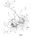
- Fig. 1 is a generally designated 1 sweeper, which is provided for cleaning roads, roads o. The like. Nutz vom 2.
- the sweeper 1 is provided with a respective wheels 5, 6 and 7 and connected to a handlebar 3 chassis 4.
- the two wheels 5 and 6 are provided as a mirror image of the longitudinal center plane M of the sweeper 1 arranged support wheels, so that a first transverse axis 8 is defined and provided as an impeller wheel 7 forms a second transverse axis 9 on the biaxial chassis 4.
- the chassis 4 is provided with a cover 10, under which a sweeping roller 11 is provided. This sweeping roller 11 is held substantially with a parallel to the transverse axes 8 and 9 longitudinal axis 12 and cooperates with a drive member 13 so that when not rotating sweeping roller 11 not shown debris from the sweeping surface 2 is receivable.
- the sweeping machine 1 has a construction in which the chassis 4 and the sweeping roller 11 which can be placed on the sweeping surface 2 are moved by their rotational movement (arrow A, FIG. Fig. 2 ) automatically displaceable function module F form, such that it is to be guided when sweeping only by means of the handlebar 3 by hand in a designated direction of travel (V, V, V '). It is understood that in this intended use of the functional assembly F, the decrease of the sweeping material from the effective area 2 takes place (arrow A, Fig. 2 ) and in particular a transfer into a collecting container 14 (FIG. Fig. 2 ) is provided.
- This interaction of the parts of the functional assembly F is tunable so that the automatic displacement in the direction of travel (V, V, V ”) and the sweeping up and forwarding take place synchronously in that a restraining force (arrow K, Fig. 1 ) is used on the handlebar 3.
- This retaining component is largely variable according to the respective friction conditions of the sweeping roller 11 on the surface 2.
- the sweeper 1 is (not shown) in the region of the drive member 13 or a gear connected to this so designed that with a reversible direction of rotation of the sweeping roller 11 and the corresponding direction of travel can be reversible (not shown).
- a both the front support wheels 5 and 6 and the rear wheel 7 detected steering unit 16 is provided.
- this embodiment is - related on the respective direction of travel V, V ', V "- the steering unit 16 with the wheels 5 and 6 arranged in front of the axis defining a roller 12.
- the guide rail 17 having a handlebar 3 in the middle longitudinal plane M is connected to the steering unit 16 in such a way that a vertical vertical axis H is defined in the connection region.
- an arcuate handle 18 is provided, with which in respective operating positions ( FIG. 3 to FIG.
- Fig. 3 shows the plan view of the sweeper 1 whose design in the region of the cover 10, the respective acute angles to the central longitudinal plane M extending edge contours 21 and 22 limit the effective range of the sweeping roller 11 and the brush parts 15 'widening space. This ensures that when using the sweeper 1, the respective outer brush parts 15 'for sweeping on a wall 23, 23' ( Fig. 4, Fig. 5 ) protrude so far that a wall-engaging sweeping process is feasible.
- Fig. 4 is indicated by the arrow B ', the sweeping or movement direction for the debris, wherein the retaining force K acts on the handle 18 substantially parallel to this direction.
- This restraining force is largely variable, according to the respective conditions of use directions or force vectors according to the arrows K ', K "are conceivable with the steering unit 16.
- a respective oblique position S, S' of the wheels 5, 6 and 7 can be predetermined with the steering unit 16, so that along the walls 23 and 23 'is defined a respective velocity vector representing travel direction V', V "and a wall area delimited by the walls can be cleaned by the brush parts 15 '.
- the lateral forces generated by the brush parts 15 ' are received by the wheels 5, 6 and 7 and the operator in the area of the handlebar 3.
- the link 3, which is set free for free travel can also be mounted in the vicinity of the running wheel 7 with the chassis 4 (eg in the region of the vertical axis H '). Fig. 10 ), so that the operating distance L changes to the dimension L 'and thus the user is closer to the machine 1.
- an additional steering linkage (not shown) may be provided in the region of the impeller 7 or in its place the chassis 4 have two parallel support wheels. It is also conceivable to provide for the handlebar 3 further connection points on the chassis 4 and the cover 10 in order to specify freely selectable operating positions for further applications.
- Fig. 1 to 18 is the respective sweeper 1 in the region of the transverse axis 8 forming support wheels 5, 6 'connected by means of a tie rod 20, 20' with the steering unit 16.
- the support wheels 5, 6 can be aligned in particular at an acute angle to the longitudinal center plane M (angle S, S '; Fig. 4, Fig. 5 ).
- this adjustability in the region of the tie rod 20 is a respective effective direction of the sweeping roller 11 to a changed direction of travel V, V 'adaptable, as shown for example when sweeping along the walls 23, 23'.
- the steering of the sweeper 1 is carried out with the steering unit 16, which in the embodiment according to Fig. 1 to 5 is connected by respective steering arms 27, 27 'with a parallel to the tie rod 20 support strut 4' of the chassis 4.
- These steering arms 27, 27 'on the one hand form two vertical joint axes E, E' as the steering axes of the system and on the other hand detect the tie rod 20 in respective joints 44, 44 '.
- the support wheels 5, 6 are held in a respective vertical axis H ", for which purpose, for example, support forks 43, 43 'are provided ( Fig. 6 ).
- a force and torque distribution when sweeping influencing displacement of the wheels 5, 6 can be done in the manner of a steering parallelogram.
- Fig. 5 and 5a are with an offset to the roller plane M 'G, G' of the axes E, E '(and correspondingly the hinge axes 44, 44') illustrates these support positions of the wheels 5, 6.
- Fig. 6 to 8 is at an angle W or W 'by a guide 24 continuously adjustable adjustment of the rolling direction of the wheels 5 and 6 similar Fig. 4 shown, wherein a steering rod connected to the tie rod 20 '27 cooperates with a retaining bolt 28.
- the handlebar 3 according to Fig. 6 a grip bow as a handle 18 ', so that an optimal gripping position is achieved in the illustrated skew.
- the handlebar 3 is provided in this embodiment of the frame assembly with a stationary on a support plate 26 of the chassis 4 held guide rail 17, so that the tie rod 20 'can be used for a parallel adjustment and then the tension by means of the clamping screw 25' takes place.
- the sweeper 1 is the steering axis (handlebar 20, 20 ') of the support wheels 5, 6 based on the axis of rotation 8 and relative to the point of contact of the support wheels 5, 6 with the ground in the direction of travel forward. If the guide rail 17 is pivoted ( Fig. 4, 5 ), in addition to the rotation / steering of the support wheels 5, 6 in addition a lateral offset G, G 'between sweeper 1 and training wheels 5, 6 arise. This means that the sweeper 1 is offset laterally relative to the operator, so that the advantages shown in wall-mounted sweeping are achieved.
- a first possibility of changing the ground clearance of the sweeping roller 11 to the useful surface 2 is shown, in which case the setting of the respective wheels 5, 6 via telescopic support members 29 takes place.
- the sweeping roller 11 is height adjustable in the region of this provided on the chassis 4 bracket, which is also conceivable to set an adjustable bracket on the cover 10.
- at least the support wheels 5 and 6 are adjustable in height, so that the brush height is to be regulated therewith (eg by means of the rotation direction arrows D, D ', D "in FIG Fig. 11 corresponding adjustment). It is also possible to adjust the height exclusively via the impeller 7 or to use all adjustment options on the wheels 5, 6 and 7, so that an advantageous parallel reduction is possible.
- the rollers of the wheels 5, 6, 7 may be supported via a strut.
- the distance of the brush to the floor or the brush pressure is thus basically specified.
- the operator has the option of influencing the brush contact pressure by raising / lowering the guide bar 17 (FIG. Fig. 2 To take arrow P).
- the three-wheeled sweeper 1 according to Fig. 12 lowers so that the guide rail 17 does not change its height as much as in the wheel adjustment according to Fig. 11 ,
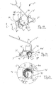
- the chassis 4 "designed as a frame has an articulated axis 30 in the region of the brush axis 12.
- the support wheels 5, 6 located on the front frame part 31 and / or the impeller 7 located on the rear frame part 32 can be changed in their distance from each other the sweeping roller 11 is adjustable over the useful surface 2, wherein an angle 33 by adjustment in the region of a groove guide 38 (FIG. Fig. 12 ) is changed.
- an angle 33 by adjustment in the region of a groove guide 38
- FIG. Fig. 13 When tilting in the area of the angle 33 (FIG. Fig. 13 ) contribute both the support wheels and the impeller in equal parts to the change in height of the sweeping brush 11 at.
- the distances T, T 'of the bending axis 30 to the respective support wheels 5, 6 and the impeller 7 are the same.
- the collecting container 14 is fastened, wherein two screws 34 are shown ( Fig. 14 ).
- the collecting container 14 is not only moved upwards at a low bending axis 30 between the frame parts 31, 32, but also towards the sweeping brush 15 (arrow 35, FIG. FIGS. 14 and FIG. 15 ).
- a bottom-side end strip 36, 36 ' is placed optimally on the useful surface 2.
- the collecting container brought closer to the sweeping brush 15, especially when the brush 15 wears and the diameter 37 changes.
- the tilting of the collecting container is reinforced when the bending axis 30 of the frame parts 31, 32 is low.
- the sweeper 1 'according to Fig. 16 has no impeller but is designed by an optimal weight distribution of the assemblies of the functional unit F 'so that the two front support wheels 5' and 6 'and the sweeping brush 15 the dead weight (arrow P') by means of a chassis 4 '"wear hard sweeping brush 15.
- the collecting container 14 can be provided with its own rollers and guided vertically, so that the collecting container 14 maintains a constant distance from the bottom 2.
- the ground clearance can also be provided by a generous rubber lip or the like strip portions 36, 36 '( Fig. 14, Fig. 15 ) are defined on the collecting container 14. With increasing wear of the sweeping brush 15 so that the sump 14 is further lowered.
- Fig. 19 shows a further special case of a sweeper 1 "without steering device, in which the handlebar 3 is attached to the guide rail 17 directly to the cover 10 '.
- the two support wheels 5" and 6 "are guided laterally next to the sweeping brush part 15 and not steerable can be achieved via an eccentric adjustment 40 (or 40 ', Fig. 20 ) change.
- impeller 7 ' may also be omitted, the distance between the Stauerradachse 8 "to the axis 12 of the sweeping roller 11 is low and thus also the possibilities for influencing the brush pressure (P", Fig. 21 ) are reduced.
- FIGS. 20 and 21 show a three-wheeled version of the sweeper 1 "(similar Fig. 19 ), whose non-pivotable wheels 5 “and 6" are held by an eccentric 40 'in the vicinity of the sweeping roller 11.
- this 3-wheel design also a rear wheel 7 "is provided and by a corresponding adjusting movement 41 in the region of the eccentric 40 ', the wheels 5" and 6 "in the intended support position are pivotable (arrow 42).
Landscapes
- Engineering & Computer Science (AREA)
- Architecture (AREA)
- Civil Engineering (AREA)
- Structural Engineering (AREA)
- Handcart (AREA)
- Cleaning Of Streets, Tracks, Or Beaches (AREA)
Claims (28)
- Balayeuse pour nettoyer des voies, des routes ou surfaces utilisables similaires, avec un châssis (4) présentant un bras oscillant (3) pour l'actionnement à la main, sur lequel des roues de roulement et/ou d'appui (5, 6, 7) définissant un essieu transversal respectif (8, 9) sont prévues par rapport au plan médian longitudinal (M) de la balayeuse (1), un rouleau de balayage (11) recevant du produit à balayer d'une surface de balayage (2) et présentant un organe d'entraînement (13), s'étendant sensiblement parallèlement aux essieux (8, 9) des roues pouvant tourner dans la zone sous un recouvrement (10) maintenu sur le châssis (4), caractérisée en ce que le châssis (4) forme avec le rouleau de balayage (11) pouvant être posé sur la surface de balayage (2) un bloc fonctionnel (F) pouvant être déplacé automatiquement par son mouvement rotatif (A), qui peut être déplacé automatiquement par le mouvement rotatif (A) du rouleau de balayage (11) dans un sens de marche (V, V', V'') prescrivant le sens de travail et peut être guidé à l'aide du bras oscillant (3) à la main dans ce sens de marche (V, V', V'') prescrit dans celui-ci.
- Balayeuse selon la revendication 1, caractérisée en ce que le mouvement rotatif (A) transmis de l'organe d'entraînement (13) seulement au rouleau de balayage (11) peut être converti à l'aide de pièces de brosse (15) pouvant être posées côté fond non seulement en un mouvement d'entraînement (B) saisissant le produit à balayer mais aussi en un mouvement de roulement pouvant être influencé par la force de frottement côté sol des roues de roulement ou d'appui (5, 6, 7) de telle manière que le déplacement automatique (V, V', V'') dans le sens de la marche prescrit et la réception de produit à balayer puissent être synchronisés.
- Balayeuse selon la revendication 1 ou 2, caractérisée en ce qu'une force de retenue (K) pouvant être utilisée par l'utilisateur sur le bras oscillant (3) agit pour son guidage dans le sens de la marche (V, V', V'') respectivement prescrit.
- Balayeuse selon l'une quelconque des revendications 1 à 3, caractérisée en ce que le sens de la marche prescrit peut être modifié avec un sens de rotation commutable du rouleau de balayage (11).
- Balayeuse selon l'une quelconque des revendications 1 à 4, caractérisée en ce qu'une unité de direction (16) reliée au moins aux roues d'appui (5, 6) et appuyant le bras oscillant (3) est prévue dans la zone du châssis (4 ; 4'').
- Balayeuse selon l'une quelconque des revendications 1 à 4, caractérisée en ce qu'un bras oscillant (3) fixé sur le recouvrement (10) coagit avec l'unité de direction (16') dans la zone du châssis (4' ; 4'').
- Balayeuse selon l'une quelconque des revendications 1 à 6, caractérisée en ce que celle-ci présente une unité de direction (16) disposée dans le sens de la marche (V, V', V'') prescrit devant le rouleau de balayage (11) et les deux roues d'appui (5, 6) peuvent être commandées à la main pour le déplacement automatique à l'aide du bras oscillant (3).
- Balayeuse selon l'une quelconque des revendications 5 à 7, caractérisée en ce que le bras oscillant (3) en appui sur l'unité de direction (16) ou le recouvrement (10) peut être fixé dans une première position de guidage recouvrant le rouleau de balayage (11) ou le recouvrement (10) et peut être permuté de celle-ci dans une seconde position de guidage déplacée de 180°.
- Balayeuse selon l'une quelconque des revendications 1 à 8, caractérisée en ce que le bras oscillant (3) est relié d'une part dans la zone entre les deux roues d'appui (5, 6 ; 5', 6' ; 5'', 6'') à l'unité de direction (16) et présente d'autre part au moins une manette (18) pouvant être saisie dans les différentes positions de guidage.
- Balayeuse selon l'une quelconque des revendications 1 à 9, caractérisée en ce que celle-ci peut être déplacée non seulement pour un balayage libre déplaçant le produit à balayer sur la surface de balayage (2) mais aussi un balayage collecteur transmettant le produit à balayer dans un récipient (14) respectivement automatiquement à l'aide du rouleau de balayage (11).
- Balayeuse selon l'une quelconque des revendications 1 à 9, caractérisée en ce qu'un tablier d'arrêt saisissant le produit à balayer lors du balayage libre est prévu sur le châssis (4, 4', 4'', 4''').
- Balayeuse selon l'une quelconque des revendications 1 à 11, caractérisée en ce que les roues d'appui (5, 6) formant l'essieu transversal (8) présentent dans la zone de l'unité de direction (16) une barre d'accouplement (20) reliée au bras oscillant (3) afin que les roues d'appui (5, 6) soient orientables à angle aigu par rapport au plan médian longitudinal (M) et afin que des sens d'action respectifs du rouleau de balayage (11) soient prescriptibles dans le sens de la marche de la machine (1).
- Balayeuse selon la revendication 12, caractérisée en ce que l'unité de direction (16) peut être bloquée dans la position prescrivant le sens d'action du rouleau de balayage (11).
- Balayeuse selon la revendication 12 ou 13, caractérisée en ce que le rouleau de balayage (11) peut être réglé de manière étagée ou en continu dans son sens d'action.
- Balayeuse selon l'une quelconque des revendications 12 à 14, caractérisée en ce que l'unité de direction (16) forme dans la zone d'une barre de suspension (4') parallèle à la barre d'accouplement (20) du châssis (4) d'une part deux axes d'articulation verticaux (E, E'), dans lesquels respectivement un levier de manoeuvre (27, 27') saisissant une fourche porteuse (43, 43') des roues d'appui (5, 6) est en appui et celles-ci sont reliées d'autre part de manière articulée à la barre d'accouplement (20).
- Balayeuse selon l'une quelconque des revendications 1 à 15, caractérisée en ce que le bras oscillant (3) relié de manière emboîtable et/ou pivotante dans la zone d'un axe vertical (H) à l'unité de direction (16) est réalisé comme un longeron de guidage (17) et est pourvu, dans la zone de la manette côté extrémité (18), de tiges profilées s'étendant en forme de U.
- Balayeuse selon l'une quelconque des revendications 1 à 16, caractérisée en ce que la distance au sol prescrivant des positions d'appui respectives des pièces de brosse (15) du rouleau de balayage (11) peut être modifiée.
- Balayeuse selon la revendication 17, caractérisée en ce que le rouleau de balayage (11) peut être réglé en hauteur dans la zone d'un support prévu sur le châssis (4, 4', 4'', 4"') et/ou sur le recouvrement (10).
- Balayeuse selon la revendication 17 ou 18, caractérisée en ce que la distance au sol du rouleau de balayage (11) peut être modifiée par les roues d'appui (5, 6 ; 5', 6' ; 5'', 6'') maintenues respectivement de manière à pouvoir être réglées en hauteur sur le châssis (4, 4', 4", 4''').
- Balayeuse selon l'une quelconque des revendications 1 à 19, caractérisée en ce que son récipient collecteur (14) prévu pour le balayage collecteur est en appui dans la zone du châssis (4, 4', 4'', 4"') entre le rouleau de balayage (11) et une ou plusieurs roues de roulement (7, 7').
- Balayeuse selon l'une quelconque des revendications 1 à 20, caractérisée en ce que celle-ci ne présente que deux roues d'appui (5, 6 ; 5', 6' ; 5'', 6''), deux roues d'appui (5, 6) et une roue de roulement (7, 7') ou deux roues d'appui (5, 6) et deux roues de roulement.
- Balayeuse selon l'une quelconque des revendications 1 à 21, caractérisée en ce que le rouleau de balayage (11) est réalisé d'un seul tenant ou présente plusieurs pièces de brosse formant dans son sens longitudinal des zones de division médianes.
- Balayeuse selon l'une quelconque des revendications 1 à 22, caractérisée en ce qu'un moteur de combustion interne ou électrique est prévu comme organe d'entraînement (13) du rouleau de balayage.
- Balayeuse selon l'une quelconque des revendications 1 à 23, caractérisée en ce qu'un récipient collecteur (14) pourvu d'éléments d'appui (36, 36') pouvant être posés côté sol est fixé sur le châssis (4, 4', 4'', 4''').
- Balayeuse selon la revendication 24, caractérisée en ce que le récipient collecteur (14) peut être en appui côté sol avec des rouleaux d'appui respectifs et/ou des lèvres en caoutchouc.
- Balayeuse selon l'une ou plusieurs quelconques des revendications 1 à 25, caractérisée en ce que le châssis (4) et le rouleau de balayage entraîné (11) forment une unité fonctionnelle (F) qui peut être déplacée à la main contre la résistance au frottement côté sol du rouleau de balayage (11) rotatif dans le sens de la marche (V''') prescrit.
- Balayeuse selon la revendication 26, caractérisée en ce que l'unité de direction (16) présentant les roues d'appui (5, 6) est disposée dans le sens de la marche (V''') au choix devant ou derrière le rouleau de balayage (11).
- Balayeuse selon l'une quelconque des revendications 1 à 27, caractérisée en ce que seul le châssis (4"') relié au bras oscillant (3) forme avec deux roues d'appui (5', 6') et un rouleau de balayage (11) en appui parallèlement à son essieu transversal (8') une unité fonctionnelle (F') qui peut être déplacée à l'aide de la rotation (A) du rouleau de balayage (11) automatiquement dans le sens de la marche prescrit (V, V, V'').
Priority Applications (4)
| Application Number | Priority Date | Filing Date | Title |
|---|---|---|---|
| PL06002096T PL1816265T3 (pl) | 2006-02-02 | 2006-02-02 | Zamiatarka do czyszczenia dróg, ulic lub tym podobnych powierzchni użytkowych |
| EP06002096A EP1816265B1 (fr) | 2006-02-02 | 2006-02-02 | Balayeuse pour nettoyer des voies, des routes ou surfaces utilisables similaires |
| ES06002096T ES2401095T3 (es) | 2006-02-02 | 2006-02-02 | Barredora para la limpieza de caminos, calles o superficies de uso similares |
| DK06002096.3T DK1816265T3 (da) | 2006-02-02 | 2006-02-02 | Fejemaskine til rengøring af veje, gader og lignende områder |
Applications Claiming Priority (1)
| Application Number | Priority Date | Filing Date | Title |
|---|---|---|---|
| EP06002096A EP1816265B1 (fr) | 2006-02-02 | 2006-02-02 | Balayeuse pour nettoyer des voies, des routes ou surfaces utilisables similaires |
Publications (2)
| Publication Number | Publication Date |
|---|---|
| EP1816265A1 EP1816265A1 (fr) | 2007-08-08 |
| EP1816265B1 true EP1816265B1 (fr) | 2012-12-12 |
Family
ID=36579855
Family Applications (1)
| Application Number | Title | Priority Date | Filing Date |
|---|---|---|---|
| EP06002096A Active EP1816265B1 (fr) | 2006-02-02 | 2006-02-02 | Balayeuse pour nettoyer des voies, des routes ou surfaces utilisables similaires |
Country Status (4)
| Country | Link |
|---|---|
| EP (1) | EP1816265B1 (fr) |
| DK (1) | DK1816265T3 (fr) |
| ES (1) | ES2401095T3 (fr) |
| PL (1) | PL1816265T3 (fr) |
Cited By (2)
| Publication number | Priority date | Publication date | Assignee | Title |
|---|---|---|---|---|
| CN104153314A (zh) * | 2014-08-26 | 2014-11-19 | 任庆举 | 一种电动道路清扫机 |
| CN110306474A (zh) * | 2019-06-17 | 2019-10-08 | 温德清 | 一种市政广场地砖清洁设备 |
Families Citing this family (3)
| Publication number | Priority date | Publication date | Assignee | Title |
|---|---|---|---|---|
| DE102008024439A1 (de) | 2008-05-14 | 2009-11-19 | Alfred Kärcher Gmbh & Co. Kg | Fahrbares Kehrgerät |
| DE102014013451A1 (de) * | 2014-09-17 | 2016-03-17 | Julius Tielbürger GmbH & Co. KG | Reinigungsgerät |
| CN109024411B (zh) * | 2018-10-11 | 2023-11-14 | 珠海亿华电动车辆有限公司 | 一种扫刷装置和扫地机 |
Family Cites Families (3)
| Publication number | Priority date | Publication date | Assignee | Title |
|---|---|---|---|---|
| ATE44563T1 (de) * | 1984-03-16 | 1989-07-15 | Stiga Ab | Kehrmaschine. |
| DE19505156A1 (de) * | 1995-02-16 | 1996-08-22 | Matthies Hans Juergen | Handgeführtes Universalgerät für Garten- und Grundstückspflege |
| DE29920702U1 (de) * | 1999-11-25 | 2000-02-17 | Kersten, Eckhard, 19300 Grabow | Kehrmaschine |
-
2006
- 2006-02-02 EP EP06002096A patent/EP1816265B1/fr active Active
- 2006-02-02 DK DK06002096.3T patent/DK1816265T3/da active
- 2006-02-02 PL PL06002096T patent/PL1816265T3/pl unknown
- 2006-02-02 ES ES06002096T patent/ES2401095T3/es active Active
Cited By (3)
| Publication number | Priority date | Publication date | Assignee | Title |
|---|---|---|---|---|
| CN104153314A (zh) * | 2014-08-26 | 2014-11-19 | 任庆举 | 一种电动道路清扫机 |
| CN110306474A (zh) * | 2019-06-17 | 2019-10-08 | 温德清 | 一种市政广场地砖清洁设备 |
| CN110306474B (zh) * | 2019-06-17 | 2020-12-18 | 安徽远维建设有限公司 | 一种市政广场地砖清洁设备 |
Also Published As
| Publication number | Publication date |
|---|---|
| DK1816265T3 (da) | 2013-03-11 |
| EP1816265A1 (fr) | 2007-08-08 |
| ES2401095T3 (es) | 2013-04-16 |
| PL1816265T3 (pl) | 2013-05-31 |
Similar Documents
| Publication | Publication Date | Title |
|---|---|---|
| EP1964976B1 (fr) | Balayeuse à projection par le haut | |
| DE9218728U1 (de) | Scheuersaugmaschine | |
| EP1816265B1 (fr) | Balayeuse pour nettoyer des voies, des routes ou surfaces utilisables similaires | |
| EP1241298B1 (fr) | Véhicule, notamment pour le nettoyage des plages | |
| EP1531202B1 (fr) | Balayeuse | |
| DE9421472U1 (de) | Kehrfahrzeug | |
| EP4445818A2 (fr) | Dispositif de nettoyage de sol, en particulier dispositif de nettoyage de sol par aspiration et récure, présentant des propriétés de manoeuvre améliorées | |
| EP3825465B1 (fr) | Balayeuse automatique permettant de nettoyer des surfaces de sol routières ou piétonnes | |
| DE2352638C3 (de) | Vorrichtung zum Reinigen von Gießscheiben für die Herstellung von Betonrohren | |
| DE202017005125U1 (de) | Kehrmaschinengehäuse | |
| EP0980802A2 (fr) | Procédé et installation de traitement d'un véhicule, en particulier installation de lavage ou de polissage | |
| EP0678621A2 (fr) | Machine aspirant du ballast | |
| DE19637685C2 (de) | Reinigungsmaschine mit einschwenkbarer Seitenbürste | |
| DE4019550A1 (de) | Kehrmaschine | |
| DE102014101760A1 (de) | Anbau-Kehrmaschine für einen Schmalspur-Frontgeräteträger | |
| DE19728441C1 (de) | Reinigungsgerät | |
| DE4143123A1 (de) | Kehrmaschine | |
| DE3512730A1 (de) | Strassenkehrmaschine | |
| EP3644817B1 (fr) | Machine de nettoyage de sol comprenant un dispositif de positionnement destiné à un outil de balayage | |
| EP1081288B1 (fr) | Balayeuse | |
| DE29814661U1 (de) | Handverfahrbares Gerät mit absenkbarem Werkzeug | |
| DE19837038C1 (de) | Handverfahrbares Gerät mit absenkbarem Werkzeug | |
| DE8907418U1 (de) | Kehrmaschine | |
| DE4016154C2 (fr) | ||
| EP4195988B1 (fr) | Appareil de traitement de plancher |
Legal Events
| Date | Code | Title | Description |
|---|---|---|---|
| PUAI | Public reference made under article 153(3) epc to a published international application that has entered the european phase |
Free format text: ORIGINAL CODE: 0009012 |
|
| AK | Designated contracting states |
Kind code of ref document: A1 Designated state(s): AT BE BG CH CY CZ DE DK EE ES FI FR GB GR HU IE IS IT LI LT LU LV MC NL PL PT RO SE SI SK TR |
|
| AX | Request for extension of the european patent |
Extension state: AL BA HR MK YU |
|
| 17P | Request for examination filed |
Effective date: 20070914 |
|
| 17Q | First examination report despatched |
Effective date: 20071023 |
|
| AKX | Designation fees paid |
Designated state(s): AT BE BG CH CY CZ DE DK EE ES FI FR GB GR HU IE IS IT LI LT LU LV MC NL PL PT RO SE SI SK TR |
|
| GRAP | Despatch of communication of intention to grant a patent |
Free format text: ORIGINAL CODE: EPIDOSNIGR1 |
|
| GRAS | Grant fee paid |
Free format text: ORIGINAL CODE: EPIDOSNIGR3 |
|
| GRAA | (expected) grant |
Free format text: ORIGINAL CODE: 0009210 |
|
| AK | Designated contracting states |
Kind code of ref document: B1 Designated state(s): AT BE BG CH CY CZ DE DK EE ES FI FR GB GR HU IE IS IT LI LT LU LV MC NL PL PT RO SE SI SK TR |
|
| REG | Reference to a national code |
Ref country code: GB Ref legal event code: FG4D Free format text: NOT ENGLISH |
|
| REG | Reference to a national code |
Ref country code: CH Ref legal event code: EP |
|
| REG | Reference to a national code |
Ref country code: AT Ref legal event code: REF Ref document number: 588405 Country of ref document: AT Kind code of ref document: T Effective date: 20121215 |
|
| REG | Reference to a national code |
Ref country code: IE Ref legal event code: FG4D Free format text: LANGUAGE OF EP DOCUMENT: GERMAN |
|
| REG | Reference to a national code |
Ref country code: CH Ref legal event code: NV Representative=s name: SCHNEIDER FELDMANN AG PATENT- UND MARKENANWAEL, CH |
|
| REG | Reference to a national code |
Ref country code: DE Ref legal event code: R096 Ref document number: 502006012295 Country of ref document: DE Effective date: 20130207 |
|
| REG | Reference to a national code |
Ref country code: CH Ref legal event code: NV Representative=s name: SCHNEIDER FELDMANN AG PATENT- UND MARKENANWAEL, CH |
|
| REG | Reference to a national code |
Ref country code: DK Ref legal event code: T3 |
|
| REG | Reference to a national code |
Ref country code: SE Ref legal event code: TRGR |
|
| REG | Reference to a national code |
Ref country code: NL Ref legal event code: T3 |
|
| REG | Reference to a national code |
Ref country code: ES Ref legal event code: FG2A Ref document number: 2401095 Country of ref document: ES Kind code of ref document: T3 Effective date: 20130416 |
|
| PG25 | Lapsed in a contracting state [announced via postgrant information from national office to epo] |
Ref country code: LT Free format text: LAPSE BECAUSE OF FAILURE TO SUBMIT A TRANSLATION OF THE DESCRIPTION OR TO PAY THE FEE WITHIN THE PRESCRIBED TIME-LIMIT Effective date: 20121212 |
|
| REG | Reference to a national code |
Ref country code: LT Ref legal event code: MG4D |
|
| PG25 | Lapsed in a contracting state [announced via postgrant information from national office to epo] |
Ref country code: LV Free format text: LAPSE BECAUSE OF FAILURE TO SUBMIT A TRANSLATION OF THE DESCRIPTION OR TO PAY THE FEE WITHIN THE PRESCRIBED TIME-LIMIT Effective date: 20121212 Ref country code: GR Free format text: LAPSE BECAUSE OF FAILURE TO SUBMIT A TRANSLATION OF THE DESCRIPTION OR TO PAY THE FEE WITHIN THE PRESCRIBED TIME-LIMIT Effective date: 20130313 Ref country code: SI Free format text: LAPSE BECAUSE OF FAILURE TO SUBMIT A TRANSLATION OF THE DESCRIPTION OR TO PAY THE FEE WITHIN THE PRESCRIBED TIME-LIMIT Effective date: 20121212 |
|
| REG | Reference to a national code |
Ref country code: PL Ref legal event code: T3 |
|
| PG25 | Lapsed in a contracting state [announced via postgrant information from national office to epo] |
Ref country code: IS Free format text: LAPSE BECAUSE OF FAILURE TO SUBMIT A TRANSLATION OF THE DESCRIPTION OR TO PAY THE FEE WITHIN THE PRESCRIBED TIME-LIMIT Effective date: 20130412 Ref country code: SK Free format text: LAPSE BECAUSE OF FAILURE TO SUBMIT A TRANSLATION OF THE DESCRIPTION OR TO PAY THE FEE WITHIN THE PRESCRIBED TIME-LIMIT Effective date: 20121212 Ref country code: EE Free format text: LAPSE BECAUSE OF FAILURE TO SUBMIT A TRANSLATION OF THE DESCRIPTION OR TO PAY THE FEE WITHIN THE PRESCRIBED TIME-LIMIT Effective date: 20121212 Ref country code: BG Free format text: LAPSE BECAUSE OF FAILURE TO SUBMIT A TRANSLATION OF THE DESCRIPTION OR TO PAY THE FEE WITHIN THE PRESCRIBED TIME-LIMIT Effective date: 20130312 Ref country code: CY Free format text: LAPSE BECAUSE OF FAILURE TO SUBMIT A TRANSLATION OF THE DESCRIPTION OR TO PAY THE FEE WITHIN THE PRESCRIBED TIME-LIMIT Effective date: 20121212 |
|
| PG25 | Lapsed in a contracting state [announced via postgrant information from national office to epo] |
Ref country code: RO Free format text: LAPSE BECAUSE OF FAILURE TO SUBMIT A TRANSLATION OF THE DESCRIPTION OR TO PAY THE FEE WITHIN THE PRESCRIBED TIME-LIMIT Effective date: 20121212 Ref country code: PT Free format text: LAPSE BECAUSE OF FAILURE TO SUBMIT A TRANSLATION OF THE DESCRIPTION OR TO PAY THE FEE WITHIN THE PRESCRIBED TIME-LIMIT Effective date: 20130412 |
|
| PLBI | Opposition filed |
Free format text: ORIGINAL CODE: 0009260 |
|
| PG25 | Lapsed in a contracting state [announced via postgrant information from national office to epo] |
Ref country code: MC Free format text: LAPSE BECAUSE OF NON-PAYMENT OF DUE FEES Effective date: 20130228 |
|
| PLAX | Notice of opposition and request to file observation + time limit sent |
Free format text: ORIGINAL CODE: EPIDOSNOBS2 |
|
| 26 | Opposition filed |
Opponent name: ALFRED KAERCHER GMBH & CO. KG Effective date: 20130912 |
|
| REG | Reference to a national code |
Ref country code: IE Ref legal event code: MM4A |
|
| REG | Reference to a national code |
Ref country code: DE Ref legal event code: R026 Ref document number: 502006012295 Country of ref document: DE Effective date: 20130912 |
|
| REG | Reference to a national code |
Ref country code: HU Ref legal event code: AG4A Ref document number: E017877 Country of ref document: HU |
|
| PG25 | Lapsed in a contracting state [announced via postgrant information from national office to epo] |
Ref country code: IE Free format text: LAPSE BECAUSE OF NON-PAYMENT OF DUE FEES Effective date: 20130202 |
|
| PLAF | Information modified related to communication of a notice of opposition and request to file observations + time limit |
Free format text: ORIGINAL CODE: EPIDOSCOBS2 |
|
| PLBB | Reply of patent proprietor to notice(s) of opposition received |
Free format text: ORIGINAL CODE: EPIDOSNOBS3 |
|
| PG25 | Lapsed in a contracting state [announced via postgrant information from national office to epo] |
Ref country code: LU Free format text: LAPSE BECAUSE OF NON-PAYMENT OF DUE FEES Effective date: 20130202 |
|
| REG | Reference to a national code |
Ref country code: FR Ref legal event code: PLFP Year of fee payment: 11 |
|
| PLCK | Communication despatched that opposition was rejected |
Free format text: ORIGINAL CODE: EPIDOSNREJ1 |
|
| APAH | Appeal reference modified |
Free format text: ORIGINAL CODE: EPIDOSCREFNO |
|
| APBM | Appeal reference recorded |
Free format text: ORIGINAL CODE: EPIDOSNREFNO |
|
| APBP | Date of receipt of notice of appeal recorded |
Free format text: ORIGINAL CODE: EPIDOSNNOA2O |
|
| APBQ | Date of receipt of statement of grounds of appeal recorded |
Free format text: ORIGINAL CODE: EPIDOSNNOA3O |
|
| REG | Reference to a national code |
Ref country code: FR Ref legal event code: PLFP Year of fee payment: 12 |
|
| PGFP | Annual fee paid to national office [announced via postgrant information from national office to epo] |
Ref country code: PL Payment date: 20161221 Year of fee payment: 12 |
|
| PGFP | Annual fee paid to national office [announced via postgrant information from national office to epo] |
Ref country code: FI Payment date: 20170224 Year of fee payment: 12 Ref country code: SE Payment date: 20170222 Year of fee payment: 12 |
|
| PGFP | Annual fee paid to national office [announced via postgrant information from national office to epo] |
Ref country code: CZ Payment date: 20161230 Year of fee payment: 12 Ref country code: AT Payment date: 20170223 Year of fee payment: 12 Ref country code: BE Payment date: 20170224 Year of fee payment: 12 Ref country code: DK Payment date: 20170125 Year of fee payment: 12 Ref country code: HU Payment date: 20170112 Year of fee payment: 12 |
|
| PGFP | Annual fee paid to national office [announced via postgrant information from national office to epo] |
Ref country code: ES Payment date: 20170220 Year of fee payment: 12 Ref country code: TR Payment date: 20170103 Year of fee payment: 12 |
|
| PGFP | Annual fee paid to national office [announced via postgrant information from national office to epo] |
Ref country code: CH Payment date: 20170529 Year of fee payment: 12 |
|
| REG | Reference to a national code |
Ref country code: FR Ref legal event code: PLFP Year of fee payment: 13 |
|
| PLAB | Opposition data, opponent's data or that of the opponent's representative modified |
Free format text: ORIGINAL CODE: 0009299OPPO |
|
| R26 | Opposition filed (corrected) |
Opponent name: ALFRED KAERCHER SE CO. KG Effective date: 20130912 |
|
| RAP4 | Party data changed (patent owner data changed or rights of a patent transferred) |
Owner name: JULIUS TIELBUERGER GMBH & CO. KG |
|
| REG | Reference to a national code |
Ref country code: CH Ref legal event code: PL |
|
| REG | Reference to a national code |
Ref country code: DK Ref legal event code: EBP Effective date: 20180228 |
|
| REG | Reference to a national code |
Ref country code: SE Ref legal event code: EUG |
|
| REG | Reference to a national code |
Ref country code: AT Ref legal event code: MM01 Ref document number: 588405 Country of ref document: AT Kind code of ref document: T Effective date: 20180202 |
|
| PG25 | Lapsed in a contracting state [announced via postgrant information from national office to epo] |
Ref country code: SE Free format text: LAPSE BECAUSE OF NON-PAYMENT OF DUE FEES Effective date: 20180203 Ref country code: FI Free format text: LAPSE BECAUSE OF NON-PAYMENT OF DUE FEES Effective date: 20180202 Ref country code: HU Free format text: LAPSE BECAUSE OF NON-PAYMENT OF DUE FEES Effective date: 20180203 |
|
| REG | Reference to a national code |
Ref country code: BE Ref legal event code: MM Effective date: 20180228 |
|
| PG25 | Lapsed in a contracting state [announced via postgrant information from national office to epo] |
Ref country code: LI Free format text: LAPSE BECAUSE OF NON-PAYMENT OF DUE FEES Effective date: 20180228 Ref country code: CZ Free format text: LAPSE BECAUSE OF NON-PAYMENT OF DUE FEES Effective date: 20180202 Ref country code: CH Free format text: LAPSE BECAUSE OF NON-PAYMENT OF DUE FEES Effective date: 20180228 Ref country code: AT Free format text: LAPSE BECAUSE OF NON-PAYMENT OF DUE FEES Effective date: 20180202 |
|
| PG25 | Lapsed in a contracting state [announced via postgrant information from national office to epo] |
Ref country code: DK Free format text: LAPSE BECAUSE OF NON-PAYMENT OF DUE FEES Effective date: 20180228 |
|
| PG25 | Lapsed in a contracting state [announced via postgrant information from national office to epo] |
Ref country code: BE Free format text: LAPSE BECAUSE OF NON-PAYMENT OF DUE FEES Effective date: 20180228 |
|
| PG25 | Lapsed in a contracting state [announced via postgrant information from national office to epo] |
Ref country code: PL Free format text: LAPSE BECAUSE OF NON-PAYMENT OF DUE FEES Effective date: 20180202 |
|
| REG | Reference to a national code |
Ref country code: ES Ref legal event code: FD2A Effective date: 20190801 |
|
| PG25 | Lapsed in a contracting state [announced via postgrant information from national office to epo] |
Ref country code: ES Free format text: LAPSE BECAUSE OF NON-PAYMENT OF DUE FEES Effective date: 20180203 |
|
| REG | Reference to a national code |
Ref country code: DE Ref legal event code: R100 Ref document number: 502006012295 Country of ref document: DE |
|
| APBU | Appeal procedure closed |
Free format text: ORIGINAL CODE: EPIDOSNNOA9O |
|
| PLBN | Opposition rejected |
Free format text: ORIGINAL CODE: 0009273 |
|
| STAA | Information on the status of an ep patent application or granted ep patent |
Free format text: STATUS: OPPOSITION REJECTED |
|
| 27O | Opposition rejected |
Effective date: 20200916 |
|
| PG25 | Lapsed in a contracting state [announced via postgrant information from national office to epo] |
Ref country code: TR Free format text: LAPSE BECAUSE OF NON-PAYMENT OF DUE FEES Effective date: 20180202 |
|
| PGFP | Annual fee paid to national office [announced via postgrant information from national office to epo] |
Ref country code: GB Payment date: 20221214 Year of fee payment: 18 |
|
| P01 | Opt-out of the competence of the unified patent court (upc) registered |
Effective date: 20230512 |
|
| PGFP | Annual fee paid to national office [announced via postgrant information from national office to epo] |
Ref country code: NL Payment date: 20240222 Year of fee payment: 19 |
|
| PGFP | Annual fee paid to national office [announced via postgrant information from national office to epo] |
Ref country code: DE Payment date: 20231219 Year of fee payment: 19 |
|
| PGFP | Annual fee paid to national office [announced via postgrant information from national office to epo] |
Ref country code: IT Payment date: 20240223 Year of fee payment: 19 Ref country code: FR Payment date: 20240220 Year of fee payment: 19 |