EP1813882A1 - Brennwertwärmetauscher - Google Patents
Brennwertwärmetauscher Download PDFInfo
- Publication number
- EP1813882A1 EP1813882A1 EP07101303A EP07101303A EP1813882A1 EP 1813882 A1 EP1813882 A1 EP 1813882A1 EP 07101303 A EP07101303 A EP 07101303A EP 07101303 A EP07101303 A EP 07101303A EP 1813882 A1 EP1813882 A1 EP 1813882A1
- Authority
- EP
- European Patent Office
- Prior art keywords
- tube
- tubes
- turns
- heat exchanger
- winding
- Prior art date
- Legal status (The legal status is an assumption and is not a legal conclusion. Google has not performed a legal analysis and makes no representation as to the accuracy of the status listed.)
- Granted
Links
- XLYOFNOQVPJJNP-UHFFFAOYSA-N water Substances O XLYOFNOQVPJJNP-UHFFFAOYSA-N 0.000 claims abstract description 11
- 238000004804 winding Methods 0.000 claims description 80
- 239000007789 gas Substances 0.000 claims description 42
- 239000012530 fluid Substances 0.000 claims description 22
- 238000009833 condensation Methods 0.000 claims description 13
- 230000005494 condensation Effects 0.000 claims description 13
- 229910052751 metal Inorganic materials 0.000 claims description 6
- 239000002184 metal Substances 0.000 claims description 6
- 239000000470 constituent Substances 0.000 claims description 3
- 239000004020 conductor Substances 0.000 abstract description 2
- 230000004907 flux Effects 0.000 description 7
- 240000008042 Zea mays Species 0.000 description 4
- 230000007423 decrease Effects 0.000 description 4
- 238000010438 heat treatment Methods 0.000 description 4
- 125000006850 spacer group Chemical group 0.000 description 4
- 239000000446 fuel Substances 0.000 description 3
- 239000010935 stainless steel Substances 0.000 description 3
- 229910001220 stainless steel Inorganic materials 0.000 description 3
- 241001080024 Telles Species 0.000 description 2
- 229910052782 aluminium Inorganic materials 0.000 description 2
- XAGFODPZIPBFFR-UHFFFAOYSA-N aluminium Chemical compound [Al] XAGFODPZIPBFFR-UHFFFAOYSA-N 0.000 description 2
- 238000005452 bending Methods 0.000 description 2
- 230000006835 compression Effects 0.000 description 2
- 238000007906 compression Methods 0.000 description 2
- 238000004519 manufacturing process Methods 0.000 description 2
- 230000000750 progressive effect Effects 0.000 description 2
- 230000009467 reduction Effects 0.000 description 2
- RYGMFSIKBFXOCR-UHFFFAOYSA-N Copper Chemical compound [Cu] RYGMFSIKBFXOCR-UHFFFAOYSA-N 0.000 description 1
- 230000009471 action Effects 0.000 description 1
- 229910045601 alloy Inorganic materials 0.000 description 1
- 239000000956 alloy Substances 0.000 description 1
- 230000005540 biological transmission Effects 0.000 description 1
- 230000008859 change Effects 0.000 description 1
- 238000006243 chemical reaction Methods 0.000 description 1
- 239000000567 combustion gas Substances 0.000 description 1
- 239000002131 composite material Substances 0.000 description 1
- 238000001816 cooling Methods 0.000 description 1
- 229910052802 copper Inorganic materials 0.000 description 1
- 239000010949 copper Substances 0.000 description 1
- 230000003247 decreasing effect Effects 0.000 description 1
- 238000011038 discontinuous diafiltration by volume reduction Methods 0.000 description 1
- 238000000605 extraction Methods 0.000 description 1
- 239000003546 flue gas Substances 0.000 description 1
- ZZUFCTLCJUWOSV-UHFFFAOYSA-N furosemide Chemical compound C1=C(Cl)C(S(=O)(=O)N)=CC(C(O)=O)=C1NCC1=CC=CO1 ZZUFCTLCJUWOSV-UHFFFAOYSA-N 0.000 description 1
- 239000011810 insulating material Substances 0.000 description 1
- 239000007788 liquid Substances 0.000 description 1
- 239000007791 liquid phase Substances 0.000 description 1
- 150000002739 metals Chemical class 0.000 description 1
- 229910000510 noble metal Inorganic materials 0.000 description 1
- 239000007800 oxidant agent Substances 0.000 description 1
- 230000001590 oxidative effect Effects 0.000 description 1
- 230000002093 peripheral effect Effects 0.000 description 1
- 230000005855 radiation Effects 0.000 description 1
- 239000011819 refractory material Substances 0.000 description 1
- 239000000779 smoke Substances 0.000 description 1
- 239000002470 thermal conductor Substances 0.000 description 1
- 238000011144 upstream manufacturing Methods 0.000 description 1
- 239000012808 vapor phase Substances 0.000 description 1
Images


Classifications
-
- F—MECHANICAL ENGINEERING; LIGHTING; HEATING; WEAPONS; BLASTING
- F28—HEAT EXCHANGE IN GENERAL
- F28D—HEAT-EXCHANGE APPARATUS, NOT PROVIDED FOR IN ANOTHER SUBCLASS, IN WHICH THE HEAT-EXCHANGE MEDIA DO NOT COME INTO DIRECT CONTACT
- F28D7/00—Heat-exchange apparatus having stationary tubular conduit assemblies for both heat-exchange media, the media being in contact with different sides of a conduit wall
- F28D7/02—Heat-exchange apparatus having stationary tubular conduit assemblies for both heat-exchange media, the media being in contact with different sides of a conduit wall the conduits being helically coiled
- F28D7/024—Heat-exchange apparatus having stationary tubular conduit assemblies for both heat-exchange media, the media being in contact with different sides of a conduit wall the conduits being helically coiled the conduits of only one medium being helically coiled tubes, the coils having a cylindrical configuration
-
- F—MECHANICAL ENGINEERING; LIGHTING; HEATING; WEAPONS; BLASTING
- F24—HEATING; RANGES; VENTILATING
- F24H—FLUID HEATERS, e.g. WATER OR AIR HEATERS, HAVING HEAT-GENERATING MEANS, e.g. HEAT PUMPS, IN GENERAL
- F24H8/00—Fluid heaters characterised by means for extracting latent heat from flue gases by means of condensation
-
- Y—GENERAL TAGGING OF NEW TECHNOLOGICAL DEVELOPMENTS; GENERAL TAGGING OF CROSS-SECTIONAL TECHNOLOGIES SPANNING OVER SEVERAL SECTIONS OF THE IPC; TECHNICAL SUBJECTS COVERED BY FORMER USPC CROSS-REFERENCE ART COLLECTIONS [XRACs] AND DIGESTS
- Y02—TECHNOLOGIES OR APPLICATIONS FOR MITIGATION OR ADAPTATION AGAINST CLIMATE CHANGE
- Y02B—CLIMATE CHANGE MITIGATION TECHNOLOGIES RELATED TO BUILDINGS, e.g. HOUSING, HOUSE APPLIANCES OR RELATED END-USER APPLICATIONS
- Y02B30/00—Energy efficient heating, ventilation or air conditioning [HVAC]
Definitions
- the present invention relates to a condensing heat exchanger.
- a condensing heat exchanger which comprises a tube made of a thermally good conductive and helically wound metal, disposed inside a gas-tight envelope, and whose turns are slightly spaced apart. on the other a gap of small width, this tube being traversed by a fluid to be heated, such as water in particular.
- a burner (fuel or gas) is adapted to generate hot gases inside the helical winding formed by said tube so that they pass through the inter-turns interstices of the inside to the outside, so as to heat the fluid flowing in the tube.
- the cooled gases, which have passed through the turns, are evacuated via an appropriate sleeve which is provided with the envelope.
- the tube has an oval section, so that two adjacent turns of the winding are facing flat faces which determine a gap of constant height and relatively small value relative to the thickness of the tube.
- a condensing heat exchanger equipped with such a "round tube” winding is therefore inefficient.
- the outer tube has a pitch equal to that of the inner tube, and a winding diameter slightly greater than that of the latter, and it is arranged concentrically around the inner winding, but with a shift of half a step in the direction axial.
- Both tubes have the same diameter.
- the inner zone of the outer tube is opposite the gap of the inner winding so that it is licked by the hot gases passing through it, which substantially increases the quality of the exchange. thermal. According to US 5,687,678 this is further improved by the presence of deflectors on the outside of this double winding, so that almost all the surface of the outer tube is licked by the gases that have already passed through the inner winding.
- the tubes are provided with annular fins, intended to further improve the capture and transfer of heat, and which, in addition, abutting against each other, determine and calibrate the passage sections of the gases (in the manner of spacers).
- the radial size of the exchanger remains limited, because of the small difference in diameter of the two windings, which are somehow imbricated one in the other.
- the present invention aims to optimize the performance of this kind of exchanger, by playing on the values of the minimum sections of the different passages offered to hot gases, from the inside to the outside of the tubular windings through their interstices and through the spaces separating two adjacent tubes, so that the velocity of these gases remains constant, or approximately constant, during their journey from the burner to the space external device to the windings, despite the progressive lowering of temperature -and correlatively the decrease in volume- of said gases.
- the condensing heat exchanger which is the subject of the invention comprises a first tube of circular section, or very slightly ovalized, helically wound disposed inside a gas-tight envelope, and whose turns are slightly spaced apart from each other by a gap of small width -designation a1 thereafter-, this tube being traversed by a fluid to be heated, such as water in particular, a burner being adapted to generate gases hot inside this helical tube so that they cross these interstices from the inside to the outside, so as to heat the fluid flowing in the tube.
- a fluid to be heated such as water in particular, a burner being adapted to generate gases hot inside this helical tube so that they cross these interstices from the inside to the outside, so as to heat the fluid flowing in the tube.
- This exchanger furthermore comprises, as the devices described in the documents US 5687678 and DE 299 06481 U , considered as representative of the state of the art closest to the invention, at least a second tube of circular section, or slightly oval, helically wound, and also traversed by a fluid to be heated, whose pitch is equal to that of the first tube, but whose winding diameter is greater than that of the first tube, the helical winding that constitutes this second tube being arranged concentrically around the helical winding that constitutes the first tube, but with a shift of a half pitch in the axial direction, these tubes being made of a thermally good conductor metal, and said casing being provided with a sleeve for evacuating the cooled gases which have passed through the turns of each winding.
- the spacing b has a value slightly less than half of a1 , and slightly greater than half of a2 .
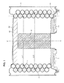
- the heat exchanger shown in FIGS. 1 to 7 comprises a pair of coaxial helically shaped tubular windings of axis X-X ', one inside 1, the other outside 2.
- the facade 4A has the form of a frame having a central opening closed by a removable cover 5, of substantially discoidal shape, which is fixed with screws for example.
- This cover is for example made of composite material, resistant to heat.
- the bottom 4B is lined internally with a discoid plate of thermally insulating and refractory material, able to withstand high temperatures.
- lid 5 which is lined internally with an annular plate 50 having similar characteristics, and is provided at its center with a burner 8 gas or fuel.
- the burner is a cylindrical burner, of axis XX '; however, the burner could have another form, provided that the gases it generates occupy the space inside the tube winding 1.
- This burner is supplied with fuel and oxidant by appropriate means not shown, well known to those skilled in the art.
- the tubes 1 and 2 are connected in series, by means of a bent pipe, in the shape of a "U”, designated 9 in FIGS. 3 and 4.
- the tube 2 has a mouthpiece 200 intended to be connected to a conduit for supplying the fluid to be heated (arrow E, FIG. 4) while, similarly, the tube 1 has a mouthpiece 100 intended to be connected to a conduit of output of the heated fluid (arrow S, Figure 4).
- This fluid is for example water used for domestic purposes, to supply the radiators of a central heating system or to produce hot water.
- Figures 5 to 7 show the relative positions of the two helical tubes 1 and 2, the burner 8 (not shown) being located on the right of these figures.
- the two windings are shifted longitudinally (along XX ') by a value of half a step P1 / 2 (or P2 / 2).
- the inter-turn gap of the inner winding 1 opens radially opposite the inner face of the section of the outer tube 2.
- D1 and D2 respectively denote the outside diameters of the two tube sections 1 and 2.
- D1 is slightly less than D2.
- the tubes 2 and 1 are traveled (in this order) by the water to be heated.
- the partially cooled gas stream then encounters f the internal area of tube 2 and is split into two substreams symbolized by the arrows g.
- the two oblique flows g then combine to form a current h which passes in the interstellar interstice of the outer tube 2, similarly heating the liquid flowing therethrough.
- references a1 and a2 denote the values of the spaces - or interstices - separating two turns of the tubes 1 and 2 respectively.
- the reference b denotes the value of the minimum space separating the two tubes 1 and 2.
- these values are chosen so as to take account of the progressive temperature reduction of this gaseous stream, and of the resulting volume reduction by applying the laws of thermodynamics, in order to that the speed of passage of gases remains almost constant, or, in any case, varies little, from the inside to the outside of the windings.
- b has a value slightly less than half of a1, whereas a2 has a value close to 2b or slightly less than this value (and therefore also less than a1 ).
- Each tube 1 and 2 comprises two series of bosses 10-13 and 20-21 regularly distributed over the entire length of the tube; as an indication we can provide between 4 and 10 bosses per turn, for each series.
- the bosses 10, 20 of the first series are turned upwards or downwards if we consider that the X-X ' axis is vertical.
- the bosses 11, 21 of the second series form an angle substantially equal to 120 ° with respect to those of the first series, if one refers to the center of the circular section of the tube.
- the stamping of the small cuvettes in the tube can be done by means of a suitable tool of known type introduced inside the tube, either in the rectilinear tube, before bending, or during this bending.
- a stamping device that may be suitable is described for example in the document EP 1 138 404 .
- the contact of a boss with the smooth part of the neighboring turn or the neighboring tube is preferably quasi-point, so as not to hinder the free passage of gases.
- the nesting one into the other of the two windings, which occurs by screwing, is advantageously with a certain tightening (without play) so as to ensure a certain contact of all the bosses 11 and 21 against the neighboring tube.
- the two windings are subjected to a slight axial compression, which may be simply due to the relative axial dimensioning of the envelope in which they are housed, so as to ensure a certain contact of all the bosses 10 and against the adjacent turns.
- This heat exchanger comprises three windings of helical tubes 1, 2 and 3 nested one inside the other.
- the relationship between the intermediate tube 2 and outer 3 is similar to that between the inner tube 1 and intermediate 2, and similar to that between the two tubes 1 and 2 of the previous embodiment.
- the pitch P3 of the tube 3 is equal to the pitch P1 and P2 of the tubes 1 and 2.
- connection pipes 9A connecting tubes 3 and 2
- 9B connecting tubes 2 and 1).
- the outer tube 3 has a mouth 300 intended to be connected to a conduit for supplying the fluid to be heated (arrow E , FIG. 10) whereas, similarly, the tube 1 has a mouthpiece 100 intended to be connected to a conduit outlet of the heated fluid (arrow S).
- this flow is subdivided into two oblique flows i, and these are joined in a radial flow j which in turn passes through the inter-turns interstices of the outer tube 3.
- the minimum spacing c between the tubes 2 and 3 has a value equal to half the value a2, or is slightly smaller than this value, and the width a3 of the interstice of the turns tube 3 is close to 2c or a little smaller than this value.
- Controlling the gas flow velocities makes it possible to maintain flows favoring heat exchanges with the wall of the tubes, which makes it possible to reduce the heat exchange surfaces and, correspondingly, to lower the cost price.
- the dimensions of the tubes are naturally adapted to the power of the exchanger, which is generally between 10 and 50 kW for domestic applications and between 50 and 1000 kW or more, for industrial applications.
- the inner windings (tube 1) and outer (tube 3) are six turns, and the intermediate winding (tube 2) is five turns.
- the other two tubes 2 'and 3' are slightly ovalized, by forming from a round tube of diameter D 1, so as to have an elliptical section, whose major axis is parallel to the axis of the windings, the small axis is therefore oriented radially.
- the flue gases emitted by the burner have a temperature of the order of 950 ° C.
- the number of winding used is not necessarily limited to three.
- one of the tubes could be mounted in parallel with the other two connected in series, the first being traversed by a first fluid and the other two by a second fluid, distinct from the first or even different nature of the first.
- bosses can naturally be used to serve as spacers in order to calibrate inter-turn and inter-tube spaces.
- inter-turn spacing it may be for example comb-shaped spacer members of the type described in the documents. WO 2005/028966 and EP 1 279 903 already mentioned.
Landscapes
- Engineering & Computer Science (AREA)
- Physics & Mathematics (AREA)
- Thermal Sciences (AREA)
- Mechanical Engineering (AREA)
- General Engineering & Computer Science (AREA)
- Heat-Exchange Devices With Radiators And Conduit Assemblies (AREA)
Applications Claiming Priority (1)
| Application Number | Priority Date | Filing Date | Title |
|---|---|---|---|
| FR0600808A FR2896856B1 (fr) | 2006-01-30 | 2006-01-30 | Echangeur de chaleur a condensation |
Publications (2)
| Publication Number | Publication Date |
|---|---|
| EP1813882A1 true EP1813882A1 (de) | 2007-08-01 |
| EP1813882B1 EP1813882B1 (de) | 2016-08-24 |
Family
ID=36954419
Family Applications (1)
| Application Number | Title | Priority Date | Filing Date |
|---|---|---|---|
| EP07101303.1A Active EP1813882B1 (de) | 2006-01-30 | 2007-01-29 | Brennwertwärmetauscher |
Country Status (2)
| Country | Link |
|---|---|
| EP (1) | EP1813882B1 (de) |
| FR (1) | FR2896856B1 (de) |
Cited By (12)
| Publication number | Priority date | Publication date | Assignee | Title |
|---|---|---|---|---|
| WO2011117802A2 (en) | 2010-03-22 | 2011-09-29 | Cosmogas S.R.L. | Heat exchanger |
| WO2011117803A2 (en) | 2010-03-22 | 2011-09-29 | Cosmogas S.R.L. | Heat exchanger |
| ITTO20110446A1 (it) * | 2011-05-19 | 2012-11-20 | Cosmogas Srl | Scambiatore di calore e procedimento di realizzazione |
| US8814560B2 (en) | 2007-12-19 | 2014-08-26 | Giannoni France | Device and method for stabilizing the pressure and the flow of a gaseous mixture supplied to a surface-combustion cylindrical burner |
| EP2685195A3 (de) * | 2012-07-11 | 2015-01-14 | Lg Electronics Inc. | Wärmetauscher |
| US9212852B2 (en) | 2012-07-11 | 2015-12-15 | Lg Electronics Inc. | Support mechanism for a heat exchanger in an air-conditioning system |
| US9677819B2 (en) | 2013-02-01 | 2017-06-13 | Lg Electronics Inc. | Air conditioner and heat exchanger therefor |
| WO2017125361A1 (fr) * | 2016-01-22 | 2017-07-27 | Sermeta | Echangeur de chaleur à condensation muni d'un dispositif d'échanges thermiques |
| US20170332513A1 (en) * | 2016-05-10 | 2017-11-16 | Remeha B.V. | Heat exchanger |
| IT201800005467A1 (it) * | 2018-05-17 | 2019-11-17 | Dispositivo di recupero calore a condensazione per una caldaia e metodo di produzione | |
| US10767900B2 (en) | 2015-05-14 | 2020-09-08 | Lochinvar, Llc | Burner with flow distribution member |
| CN113518889A (zh) * | 2019-03-05 | 2021-10-19 | 科唯怡株式会社 | 冷水制造装置 |
Families Citing this family (2)
| Publication number | Priority date | Publication date | Assignee | Title |
|---|---|---|---|---|
| FR2928442B1 (fr) | 2008-03-06 | 2010-12-17 | Mer Joseph Le | Installation de production d'eau chaude sanitaire |
| DE102011010444A1 (de) * | 2011-02-04 | 2012-08-09 | Viessmann Werke Gmbh & Co Kg | Heizkessel |
Citations (12)
| Publication number | Priority date | Publication date | Assignee | Title |
|---|---|---|---|---|
| WO1994016272A1 (fr) * | 1993-01-15 | 1994-07-21 | Joseph Le Mer | Element echangeur de chaleur, procede et dispositif pour le fabriquer |
| US5687678A (en) * | 1995-01-26 | 1997-11-18 | Weben-Jarco, Inc. | High efficiency commercial water heater |
| DE29906481U1 (de) * | 1998-04-06 | 1999-07-29 | Joh. Vaillant Gmbh U. Co, 42859 Remscheid | Wasserheizer |
| DE10002894A1 (de) * | 1999-01-21 | 2000-08-24 | Vaillant Joh Gmbh & Co | Wasserheizer |
| EP1039246A2 (de) * | 1999-03-19 | 2000-09-27 | VIESSMANN WERKE GmbH & CO. | Kompaktheizkessel |
| DE10026548C1 (de) * | 2000-05-27 | 2001-11-22 | Viessmann Werke Kg | Wendelspalt-Wärmetauscher |
| EP1243867A2 (de) * | 2001-03-24 | 2002-09-25 | Viessmann Werke GmbH & Co | Wandheizgerät für die Verbrennung flüssiger Brennstoffe |
| EP1279903A2 (de) * | 2001-07-26 | 2003-01-29 | Robert Bosch Gmbh | Wärmetauscher für ein Gasheizgerät, insbesondere für ein Brennwertgerät |
| EP1344994A2 (de) * | 2002-03-15 | 2003-09-17 | Viessmann Werke GmbH & Co KG | Kompaktheizkessel |
| EP1398580A2 (de) * | 2002-09-16 | 2004-03-17 | Vaillant GmbH | Wendelförmiger Wärmeaustauscher |
| WO2005028966A1 (en) * | 2003-09-23 | 2005-03-31 | Renato Montini | Heat exchanger |
| WO2005080900A2 (en) * | 2004-01-22 | 2005-09-01 | Cosmogas S.R.L. | A heat exchanger, in particular of the condensation type |
-
2006
- 2006-01-30 FR FR0600808A patent/FR2896856B1/fr not_active Expired - Fee Related
-
2007
- 2007-01-29 EP EP07101303.1A patent/EP1813882B1/de active Active
Patent Citations (12)
| Publication number | Priority date | Publication date | Assignee | Title |
|---|---|---|---|---|
| WO1994016272A1 (fr) * | 1993-01-15 | 1994-07-21 | Joseph Le Mer | Element echangeur de chaleur, procede et dispositif pour le fabriquer |
| US5687678A (en) * | 1995-01-26 | 1997-11-18 | Weben-Jarco, Inc. | High efficiency commercial water heater |
| DE29906481U1 (de) * | 1998-04-06 | 1999-07-29 | Joh. Vaillant Gmbh U. Co, 42859 Remscheid | Wasserheizer |
| DE10002894A1 (de) * | 1999-01-21 | 2000-08-24 | Vaillant Joh Gmbh & Co | Wasserheizer |
| EP1039246A2 (de) * | 1999-03-19 | 2000-09-27 | VIESSMANN WERKE GmbH & CO. | Kompaktheizkessel |
| DE10026548C1 (de) * | 2000-05-27 | 2001-11-22 | Viessmann Werke Kg | Wendelspalt-Wärmetauscher |
| EP1243867A2 (de) * | 2001-03-24 | 2002-09-25 | Viessmann Werke GmbH & Co | Wandheizgerät für die Verbrennung flüssiger Brennstoffe |
| EP1279903A2 (de) * | 2001-07-26 | 2003-01-29 | Robert Bosch Gmbh | Wärmetauscher für ein Gasheizgerät, insbesondere für ein Brennwertgerät |
| EP1344994A2 (de) * | 2002-03-15 | 2003-09-17 | Viessmann Werke GmbH & Co KG | Kompaktheizkessel |
| EP1398580A2 (de) * | 2002-09-16 | 2004-03-17 | Vaillant GmbH | Wendelförmiger Wärmeaustauscher |
| WO2005028966A1 (en) * | 2003-09-23 | 2005-03-31 | Renato Montini | Heat exchanger |
| WO2005080900A2 (en) * | 2004-01-22 | 2005-09-01 | Cosmogas S.R.L. | A heat exchanger, in particular of the condensation type |
Cited By (28)
| Publication number | Priority date | Publication date | Assignee | Title |
|---|---|---|---|---|
| US8814560B2 (en) | 2007-12-19 | 2014-08-26 | Giannoni France | Device and method for stabilizing the pressure and the flow of a gaseous mixture supplied to a surface-combustion cylindrical burner |
| US9194605B2 (en) | 2010-03-22 | 2015-11-24 | Cosmogas S.R.L. | Heat exchanger |
| WO2011117803A2 (en) | 2010-03-22 | 2011-09-29 | Cosmogas S.R.L. | Heat exchanger |
| KR101632469B1 (ko) | 2010-03-22 | 2016-06-21 | 코스모가스 에스.알.엘. | 열교환기 |
| KR101632468B1 (ko) | 2010-03-22 | 2016-06-21 | 코스모가스 에스.알.엘. | 열교환기 |
| US20130008635A1 (en) * | 2010-03-22 | 2013-01-10 | Cosmogas S.R.L. | Heat exchanger |
| CN102893098A (zh) * | 2010-03-22 | 2013-01-23 | 科斯莫加斯有限公司 | 换热器 |
| KR20130054254A (ko) * | 2010-03-22 | 2013-05-24 | 코스모가스 에스.알.엘. | 열교환기 |
| KR20130054253A (ko) * | 2010-03-22 | 2013-05-24 | 코스모가스 에스.알.엘. | 열교환기 |
| WO2011117802A2 (en) | 2010-03-22 | 2011-09-29 | Cosmogas S.R.L. | Heat exchanger |
| CN102893098B (zh) * | 2010-03-22 | 2016-01-20 | 科斯莫加斯有限公司 | 换热器 |
| KR101632478B1 (ko) | 2011-05-19 | 2016-06-21 | 코스모가스 에스.알.엘. | 열교환기 및 생산 과정 |
| US10030915B2 (en) | 2011-05-19 | 2018-07-24 | Cosmogas S.R.L. | Heat exchanger |
| KR20140047040A (ko) * | 2011-05-19 | 2014-04-21 | 코스모가스 에스.알.엘. | 열교환기 및 생산 과정 |
| WO2012156954A1 (en) | 2011-05-19 | 2012-11-22 | Cosmogas S.R.L. | Heat exchanger and production process |
| ITTO20110446A1 (it) * | 2011-05-19 | 2012-11-20 | Cosmogas Srl | Scambiatore di calore e procedimento di realizzazione |
| EP2685195A3 (de) * | 2012-07-11 | 2015-01-14 | Lg Electronics Inc. | Wärmetauscher |
| US9389026B2 (en) | 2012-07-11 | 2016-07-12 | Lg Electronics Inc. | Heat exchanger |
| US9212852B2 (en) | 2012-07-11 | 2015-12-15 | Lg Electronics Inc. | Support mechanism for a heat exchanger in an air-conditioning system |
| US9677819B2 (en) | 2013-02-01 | 2017-06-13 | Lg Electronics Inc. | Air conditioner and heat exchanger therefor |
| US10767900B2 (en) | 2015-05-14 | 2020-09-08 | Lochinvar, Llc | Burner with flow distribution member |
| FR3047063A1 (fr) * | 2016-01-22 | 2017-07-28 | Sermeta | Dispositif d'echanges thermiques pour echangeur de chaleur a condensation |
| WO2017125361A1 (fr) * | 2016-01-22 | 2017-07-27 | Sermeta | Echangeur de chaleur à condensation muni d'un dispositif d'échanges thermiques |
| US11079137B2 (en) | 2016-01-22 | 2021-08-03 | Sermeta | Condensation heat exchanger provided with a heat exchange device |
| US20170332513A1 (en) * | 2016-05-10 | 2017-11-16 | Remeha B.V. | Heat exchanger |
| IT201800005467A1 (it) * | 2018-05-17 | 2019-11-17 | Dispositivo di recupero calore a condensazione per una caldaia e metodo di produzione | |
| CN113518889A (zh) * | 2019-03-05 | 2021-10-19 | 科唯怡株式会社 | 冷水制造装置 |
| CN113518889B (zh) * | 2019-03-05 | 2023-11-07 | 科唯怡株式会社 | 冷水制造装置 |
Also Published As
| Publication number | Publication date |
|---|---|
| EP1813882B1 (de) | 2016-08-24 |
| FR2896856B1 (fr) | 2008-05-16 |
| FR2896856A1 (fr) | 2007-08-03 |
Similar Documents
| Publication | Publication Date | Title |
|---|---|---|
| EP1813882B1 (de) | Brennwertwärmetauscher | |
| EP2531779B1 (de) | Brennwertwärmetauscher für mehrere flüssigkeiten und brennwertkessel mit einem solchen wärmetauscher | |
| EP1618341B1 (de) | Brennwertwärmetauscher | |
| EP1561075B1 (de) | Kondensationswärmetauscher mit kunststoffmantel | |
| EP3405723B1 (de) | Kondensationswärmetauscher mit einer wärmetauschervorrichtung | |
| CA2493393C (fr) | Echangeur de chaleur a condensation a double faisceau de tubes | |
| FR2527317A1 (fr) | Chaudiere a gaz ou a combustible liquide pour la production d'eau chaude ou de vapeur | |
| EP2912396B1 (de) | Wärmetauscher, insbesondere für ein kraftfahrzeug | |
| FR2846075A1 (fr) | Echangeur de chaleur a condensation, a enveloppe plastique | |
| FR2576404A1 (fr) | Echangeur de chaleur et application a un appareil de rechauffage d'un fluide, notamment accumulateur d'eau chaude sanitaire | |
| EP0251891B1 (de) | Elektrische Heizvorrichtung mit Metallhülse | |
| EP2411117B1 (de) | Vorrichtung zum reinigen eines mit partikeln beladenen fluids durch thermophoretische kräfte | |
| EP4196253B1 (de) | Festbett-rohrreaktor | |
| EP1366326B1 (de) | Kondensierender wärmetauscher für einen kessel | |
| FR2676272A1 (fr) | Echangeur de chaleur a faisceau tubulaire. | |
| EP3354997B1 (de) | Heizkessel mit verbesserter leistung | |
| FR2850451A1 (fr) | Echangeur de chaleur a condensation, a enveloppe plastique | |
| EP1947386A1 (de) | Heizgaswirbler, insbesondere für Rauchrohrkessel und entsprechender Kessel | |
| EP4370855A1 (de) | Wärmetauscher | |
| CA3221972A1 (fr) | Echangeur de chaleur a condensation | |
| BE551685A (de) | ||
| BE447652A (de) | ||
| BE413117A (de) | ||
| CH608385A5 (en) | Group of assembled tubes for diffusers | |
| BE485665A (de) |
Legal Events
| Date | Code | Title | Description |
|---|---|---|---|
| PUAI | Public reference made under article 153(3) epc to a published international application that has entered the european phase |
Free format text: ORIGINAL CODE: 0009012 |
|
| AK | Designated contracting states |
Kind code of ref document: A1 Designated state(s): AT BE BG CH CY CZ DE DK EE ES FI FR GB GR HU IE IS IT LI LT LU LV MC NL PL PT RO SE SI SK TR |
|
| AX | Request for extension of the european patent |
Extension state: AL BA HR MK YU |
|
| RAP1 | Party data changed (applicant data changed or rights of an application transferred) |
Owner name: GIANNONI, ROCCO Owner name: LE MER, JOSEPH |
|
| RIN1 | Information on inventor provided before grant (corrected) |
Inventor name: LE MER, JOSEPH |
|
| 17P | Request for examination filed |
Effective date: 20080117 |
|
| 17Q | First examination report despatched |
Effective date: 20080214 |
|
| AKX | Designation fees paid |
Designated state(s): DE FR GB IT |
|
| RAP1 | Party data changed (applicant data changed or rights of an application transferred) |
Owner name: GIANNONI FRANCE |
|
| 111Z | Information provided on other rights and legal means of execution |
Free format text: DE FR GB IT Effective date: 20110125 |
|
| RAP1 | Party data changed (applicant data changed or rights of an application transferred) |
Owner name: SERMETA |
|
| R11X | Information provided on other rights and legal means of execution (corrected) |
Free format text: DE FR GB IT Effective date: 20141103 |
|
| REG | Reference to a national code |
Ref country code: DE Ref legal event code: R079 Ref document number: 602007047579 Country of ref document: DE Free format text: PREVIOUS MAIN CLASS: F24H0001430000 Ipc: F24H0008000000 |
|
| GRAP | Despatch of communication of intention to grant a patent |
Free format text: ORIGINAL CODE: EPIDOSNIGR1 |
|
| RIC1 | Information provided on ipc code assigned before grant |
Ipc: F28D 7/02 20060101ALI20160329BHEP Ipc: F24H 8/00 20060101AFI20160329BHEP |
|
| INTG | Intention to grant announced |
Effective date: 20160504 |
|
| GRAS | Grant fee paid |
Free format text: ORIGINAL CODE: EPIDOSNIGR3 |
|
| GRAA | (expected) grant |
Free format text: ORIGINAL CODE: 0009210 |
|
| AK | Designated contracting states |
Kind code of ref document: B1 Designated state(s): DE FR GB IT |
|
| REG | Reference to a national code |
Ref country code: GB Ref legal event code: FG4D Free format text: NOT ENGLISH |
|
| REG | Reference to a national code |
Ref country code: DE Ref legal event code: R096 Ref document number: 602007047579 Country of ref document: DE |
|
| REG | Reference to a national code |
Ref country code: FR Ref legal event code: PLFP Year of fee payment: 11 |
|
| REG | Reference to a national code |
Ref country code: DE Ref legal event code: R097 Ref document number: 602007047579 Country of ref document: DE |
|
| PLBE | No opposition filed within time limit |
Free format text: ORIGINAL CODE: 0009261 |
|
| STAA | Information on the status of an ep patent application or granted ep patent |
Free format text: STATUS: NO OPPOSITION FILED WITHIN TIME LIMIT |
|
| 26N | No opposition filed |
Effective date: 20170526 |
|
| REG | Reference to a national code |
Ref country code: FR Ref legal event code: PLFP Year of fee payment: 12 |
|
| REG | Reference to a national code |
Ref country code: FR Ref legal event code: RG Effective date: 20180108 |
|
| P01 | Opt-out of the competence of the unified patent court (upc) registered |
Effective date: 20230428 |
|
| PGFP | Annual fee paid to national office [announced via postgrant information from national office to epo] |
Ref country code: FR Payment date: 20231215 Year of fee payment: 18 |
|
| PGFP | Annual fee paid to national office [announced via postgrant information from national office to epo] |
Ref country code: DE Payment date: 20240115 Year of fee payment: 18 Ref country code: GB Payment date: 20240119 Year of fee payment: 18 |
|
| PGFP | Annual fee paid to national office [announced via postgrant information from national office to epo] |
Ref country code: IT Payment date: 20240110 Year of fee payment: 18 |