EP1812704B1 - Kraftstoffzufuhrvorrichtung - Google Patents
Kraftstoffzufuhrvorrichtung Download PDFInfo
- Publication number
- EP1812704B1 EP1812704B1 EP05806619A EP05806619A EP1812704B1 EP 1812704 B1 EP1812704 B1 EP 1812704B1 EP 05806619 A EP05806619 A EP 05806619A EP 05806619 A EP05806619 A EP 05806619A EP 1812704 B1 EP1812704 B1 EP 1812704B1
- Authority
- EP
- European Patent Office
- Prior art keywords
- fuel
- pressure
- pump
- discharge
- low
- Prior art date
- Legal status (The legal status is an assumption and is not a legal conclusion. Google has not performed a legal analysis and makes no representation as to the accuracy of the status listed.)
- Expired - Lifetime
Links
Images





Classifications
-
- F—MECHANICAL ENGINEERING; LIGHTING; HEATING; WEAPONS; BLASTING
- F02—COMBUSTION ENGINES; HOT-GAS OR COMBUSTION-PRODUCT ENGINE PLANTS
- F02D—CONTROLLING COMBUSTION ENGINES
- F02D41/00—Electrical control of supply of combustible mixture or its constituents
- F02D41/30—Controlling fuel injection
- F02D41/38—Controlling fuel injection of the high pressure type
- F02D41/3809—Common rail control systems
- F02D41/3836—Controlling the fuel pressure
- F02D41/3845—Controlling the fuel pressure by controlling the flow into the common rail, e.g. the amount of fuel pumped
- F02D41/3854—Controlling the fuel pressure by controlling the flow into the common rail, e.g. the amount of fuel pumped with elements in the low pressure part, e.g. low pressure pump
-
- F—MECHANICAL ENGINEERING; LIGHTING; HEATING; WEAPONS; BLASTING
- F02—COMBUSTION ENGINES; HOT-GAS OR COMBUSTION-PRODUCT ENGINE PLANTS
- F02D—CONTROLLING COMBUSTION ENGINES
- F02D33/00—Controlling delivery of fuel or combustion-air, not otherwise provided for
- F02D33/003—Controlling the feeding of liquid fuel from storage containers to carburettors or fuel-injection apparatus ; Failure or leakage prevention; Diagnosis or detection of failure; Arrangement of sensors in the fuel system; Electric wiring; Electrostatic discharge
-
- F—MECHANICAL ENGINEERING; LIGHTING; HEATING; WEAPONS; BLASTING
- F02—COMBUSTION ENGINES; HOT-GAS OR COMBUSTION-PRODUCT ENGINE PLANTS
- F02D—CONTROLLING COMBUSTION ENGINES
- F02D41/00—Electrical control of supply of combustible mixture or its constituents
- F02D41/30—Controlling fuel injection
- F02D41/3094—Controlling fuel injection the fuel injection being effected by at least two different injectors, e.g. one in the intake manifold and one in the cylinder
-
- F—MECHANICAL ENGINEERING; LIGHTING; HEATING; WEAPONS; BLASTING
- F02—COMBUSTION ENGINES; HOT-GAS OR COMBUSTION-PRODUCT ENGINE PLANTS
- F02M—SUPPLYING COMBUSTION ENGINES IN GENERAL WITH COMBUSTIBLE MIXTURES OR CONSTITUENTS THEREOF
- F02M37/00—Apparatus or systems for feeding liquid fuel from storage containers to carburettors or fuel-injection apparatus; Arrangements for purifying liquid fuel specially adapted for, or arranged on, internal-combustion engines
- F02M37/0047—Layout or arrangement of systems for feeding fuel
-
- F—MECHANICAL ENGINEERING; LIGHTING; HEATING; WEAPONS; BLASTING
- F02—COMBUSTION ENGINES; HOT-GAS OR COMBUSTION-PRODUCT ENGINE PLANTS
- F02M—SUPPLYING COMBUSTION ENGINES IN GENERAL WITH COMBUSTIBLE MIXTURES OR CONSTITUENTS THEREOF
- F02M63/00—Other fuel-injection apparatus having pertinent characteristics not provided for in groups F02M39/00 - F02M57/00 or F02M67/00; Details, component parts, or accessories of fuel-injection apparatus, not provided for in, or of interest apart from, the apparatus of groups F02M39/00 - F02M61/00 or F02M67/00; Combination of fuel pump with other devices, e.g. lubricating oil pump
- F02M63/02—Fuel-injection apparatus having several injectors fed by a common pumping element, or having several pumping elements feeding a common injector; Fuel-injection apparatus having provisions for cutting-out pumps, pumping elements, or injectors; Fuel-injection apparatus having provisions for variably interconnecting pumping elements and injectors alternatively
- F02M63/0225—Fuel-injection apparatus having a common rail feeding several injectors ; Means for varying pressure in common rails; Pumps feeding common rails
-
- F—MECHANICAL ENGINEERING; LIGHTING; HEATING; WEAPONS; BLASTING
- F02—COMBUSTION ENGINES; HOT-GAS OR COMBUSTION-PRODUCT ENGINE PLANTS
- F02M—SUPPLYING COMBUSTION ENGINES IN GENERAL WITH COMBUSTIBLE MIXTURES OR CONSTITUENTS THEREOF
- F02M63/00—Other fuel-injection apparatus having pertinent characteristics not provided for in groups F02M39/00 - F02M57/00 or F02M67/00; Details, component parts, or accessories of fuel-injection apparatus, not provided for in, or of interest apart from, the apparatus of groups F02M39/00 - F02M61/00 or F02M67/00; Combination of fuel pump with other devices, e.g. lubricating oil pump
- F02M63/02—Fuel-injection apparatus having several injectors fed by a common pumping element, or having several pumping elements feeding a common injector; Fuel-injection apparatus having provisions for cutting-out pumps, pumping elements, or injectors; Fuel-injection apparatus having provisions for variably interconnecting pumping elements and injectors alternatively
- F02M63/0225—Fuel-injection apparatus having a common rail feeding several injectors ; Means for varying pressure in common rails; Pumps feeding common rails
- F02M63/0275—Arrangement of common rails
- F02M63/0285—Arrangement of common rails having more than one common rail
- F02M63/029—Arrangement of common rails having more than one common rail per cylinder bank, e.g. storing different fuels or fuels at different pressure levels per cylinder bank
-
- F—MECHANICAL ENGINEERING; LIGHTING; HEATING; WEAPONS; BLASTING
- F02—COMBUSTION ENGINES; HOT-GAS OR COMBUSTION-PRODUCT ENGINE PLANTS
- F02M—SUPPLYING COMBUSTION ENGINES IN GENERAL WITH COMBUSTIBLE MIXTURES OR CONSTITUENTS THEREOF
- F02M69/00—Low-pressure fuel-injection apparatus ; Apparatus with both continuous and intermittent injection; Apparatus injecting different types of fuel
- F02M69/02—Pumps peculiar thereto
-
- F—MECHANICAL ENGINEERING; LIGHTING; HEATING; WEAPONS; BLASTING
- F02—COMBUSTION ENGINES; HOT-GAS OR COMBUSTION-PRODUCT ENGINE PLANTS
- F02M—SUPPLYING COMBUSTION ENGINES IN GENERAL WITH COMBUSTIBLE MIXTURES OR CONSTITUENTS THEREOF
- F02M69/00—Low-pressure fuel-injection apparatus ; Apparatus with both continuous and intermittent injection; Apparatus injecting different types of fuel
- F02M69/04—Injectors peculiar thereto
- F02M69/042—Positioning of injectors with respect to engine, e.g. in the air intake conduit
- F02M69/046—Positioning of injectors with respect to engine, e.g. in the air intake conduit for injecting into both the combustion chamber and the intake conduit
-
- F—MECHANICAL ENGINEERING; LIGHTING; HEATING; WEAPONS; BLASTING
- F02—COMBUSTION ENGINES; HOT-GAS OR COMBUSTION-PRODUCT ENGINE PLANTS
- F02M—SUPPLYING COMBUSTION ENGINES IN GENERAL WITH COMBUSTIBLE MIXTURES OR CONSTITUENTS THEREOF
- F02M69/00—Low-pressure fuel-injection apparatus ; Apparatus with both continuous and intermittent injection; Apparatus injecting different types of fuel
- F02M69/46—Details, component parts or accessories not provided for in, or of interest apart from, the apparatus covered by groups F02M69/02 - F02M69/44
- F02M69/462—Arrangement of fuel conduits, e.g. with valves for maintaining pressure in the pipes after the engine being shut-down
-
- F—MECHANICAL ENGINEERING; LIGHTING; HEATING; WEAPONS; BLASTING
- F02—COMBUSTION ENGINES; HOT-GAS OR COMBUSTION-PRODUCT ENGINE PLANTS
- F02M—SUPPLYING COMBUSTION ENGINES IN GENERAL WITH COMBUSTIBLE MIXTURES OR CONSTITUENTS THEREOF
- F02M59/00—Pumps specially adapted for fuel-injection and not provided for in groups F02M39/00 -F02M57/00, e.g. rotary cylinder-block type of pumps
- F02M59/20—Varying fuel delivery in quantity or timing
- F02M59/36—Varying fuel delivery in quantity or timing by variably-timed valves controlling fuel passages to pumping elements or overflow passages
- F02M59/366—Valves being actuated electrically
Definitions
- the present invention relates to a fuel supply apparatus, and more particularly to a fuel supply apparatus for an internal combustion engine having first fuel injection means (in-cylinder injector) for injecting fuel into a cylinder and second fuel injection means (intake manifold injector) for injecting fuel into an intake manifold or an intake port.
- first fuel injection means in-cylinder injector
- second fuel injection means intake manifold injector
- a fuel supply apparatus (fuel injection apparatus) provided with an intake manifold injector for injecting fuel into an intake port and an in-cylinder injector for injecting fuel into a cylinder, and controlling the intake manifold injector and the in-cylinder injector in accordance with an operation state to realize fuel injection by a combination of intake manifold injection and in-cylinder injection is known.
- a configuration is disclosed where fuel is drawn from a fuel tank by a common low-pressure fuel pump and discharged to a high-pressure fuel supply system for the in-cylinder injection and to a low-pressure fuel supply system for the intake manifold injection, and while the fuel discharged from the low-pressure fuel pump is further increased in pressure by a high-pressure fuel pump to supply the pressurized fuel to the in-cylinder injector in the high-pressure fuel supply system, the fuel discharged from the low-pressure fuel pump is injected from the intake manifold injector in the low-pressure fuel supply system (for example, Japanese Patent Laying-Open No. 2001-336439 ).
- the relevant document particularly discloses a technique of setting a ratio between the quantity of the fuel injected into the cylinder and the quantity of the fuel injected into the intake manifold taking account of the particulate state of the fuel injected into the cylinder in an internal combustion engine provided with such a fuel supply apparatus.
- Document EP 1 520 981 A2 representing prior art according to Art. 54 (3) and (4) EPC, further discloses a fuel supplying apparatus of an internal combustion engine which includes a first fuel supply system, a second fuel supply system, and a pulsation propagation suppressing unit.
- the first fuel supply system pressurizes a fuel by a low-pressure pump, and supplies the fuel pressurized by the low-pressure pump to a first fuel injection mechanism.
- the second fuel supply system is branched from the first fuel supply system, further pressurizes the fuel, pressurized by the low-pressure pump, by a high-pressure pump that is driven according to an operating state of the internal combustion engine, and supplies the fuel pressurized by the high-pressure pump to a second fuel injection mechanism.
- the pulsation propagation suppressing unit is provided in at least one of the first fuel supply system and the second fuel supply system, and suppresses propagation of a pulsation generated in the high-pressure pump to the first fuel injection mechanism.
- the low-pressure fuel pump is generally implemented with a pump of an electric motor driven type whose discharge quantity (flow rate) is controllable
- the high-pressure fuel pump is generally implemented with a pump of an engine driven type that is driven by revolution of the internal combustion engine.
- the quantity of the fuel injected from the intake manifold injector and the quantity of the fuel injected from the in-cylinder injector are controlled separately depending on the operation state of the internal combustion engine.
- control of the flow rate of the low-pressure fuel pump supplying the fuel pumped from the fuel tank commonly to the low-pressure fuel supply system and the high-pressure fuel supply system becomes important. For example, if the quantity of the fuel injected from the intake manifold injector is smaller than a required injection quantity due to an insufficient discharge quantity of the low-pressure fuel pump, the air-fuel ratio (A/F) will become lean, thereby causing failure in combustion, decrease of power output, and degradation of exhaust emission property. If the fuel supplied to the high-pressure fuel pump is insufficient, the fuel of an adequate quantity will not flow into a plunger portion constituting the high-pressure fuel pump, thereby causing operation failure due to poor lubrication of the plunger. This leads to a decrease in fuel pressure of the high-pressure fuel system, in which case in-cylinder fuel injection cannot be carried out satisfactorily, possibly making the engine stop.
- the present invention has been made to solve the above-described problems, and an object of the present invention is to provide a fuel supply apparatus for an internal combustion engine having a first fuel injection mechanism (in-cylinder injector) for injecting fuel into a cylinder and a second fuel injection mechanism (intake manifold injector) for injecting fuel into an intake manifold and/or an intake port, which is highly reliable as a discharge quantity (flow rate) of a low-pressure fuel pump supplying fuel commonly to a high-pressure fuel supply system and a low-pressure fuel supply system is optimized to prevent deterioration of fuel efficiency due to setting of excessive flow rate and to avoid operation failure due to insufficient fuel supply.
- the present invention provides a fuel supply apparatus for supplying fuel to an internal combustion engine, which includes a first fuel pump, a first fuel supply system, a second fuel supply system, and a discharge quantity calculating portion.
- the first fuel pump draws fuel from a fuel tank and discharging the fuel at a first pressure.
- the first fuel supply system includes first fuel injection mechanisms for injecting fuel into the internal combustion engine at the first pressure and a first fuel delivery pipe receiving the fuel discharged from the first fuel pump and delivering the fuel to the first fuel injection mechanisms.
- the second fuel supply system includes second fuel injection mechanisms for injecting fuel into the internal combustion engine at a second pressure that is higher than the first pressure, a second fuel pump driven by the internal combustion engine and drawing and further pressurizing the fuel discharged from the first fuel pump and discharging the fuel at the second pressure, and a second fuel delivery pipe receiving the fuel discharged from the second fuel pump and delivering the fuel to the second fuel injection mechanisms.
- the discharge quantity calculating portion obtains required supply quantities to the first and second fuel supply systems, respectively, in accordance with an operation condition of the internal combustion engine, and determines a discharge quantity from the first fuel pump based on the required supply quantities obtained.
- the discharge quantity of the first fuel pump (low-pressure fuel pump) supplying fuel commonly to the first fuel supply system (low-pressure fuel supply system) and the second fuel supply system (high-pressure fuel supply system) is set based on the required supply quantities to the first and second fuel supply systems in accordance with the operation condition of the internal combustion engine. Accordingly, it is possible to increase reliability by preventing insufficient fuel supply to the fuel supply systems, and to improve fuel efficiency by preventing an increase in power consumption by the first fuel pump due to excessive fuel supply.
- the discharge quantity calculating portion includes first through third calculating portions.
- the first calculating portion calculates the required supply quantity to the first fuel supply system based on at least a fuel injection quantity by the first fuel injection mechanisms and the number of revolutions of the internal combustion engine.
- the second calculating portion calculates the required supply quantity to the second fuel supply system based on at least the number of revolutions of the internal combustion engine.
- the third calculating portion determines the discharge quantity from the first fuel pump in accordance with a sum of the required supply quantities calculated by the first and second calculating portions.
- the required supply quantities to the fuel supply systems can be calculated appropriately and with ease in accordance with the operation condition of the internal combustion engine.
- the fuel supply apparatus further includes a fuel injection control unit.
- the fuel injection control unit controls a fuel injection ratio between the first fuel injection mechanisms and the second fuel injection mechanisms with respect to a total fuel injection quantity in accordance with an operation state of the internal combustion engine.
- the first calculating portion calculates the required supply quantity to the first fuel supply system by obtaining the fuel injection quantity of the first fuel injection mechanisms reflecting the fuel injection ratio controlled by the fuel injection control unit.
- the required supply quantity to the first fuel supply system is calculated reflecting the fuel injection ratio (DI ratio) between the first and second fuel injection mechanisms.
- DI ratio fuel injection ratio
- a plurality of second fuel delivery pipes are provided, and the second fuel injection mechanisms are divided into groups and provided respectively for the plurality of second fuel delivery pipes, and a plurality of second fuel pumps are provided respectively for the second fuel delivery pipes.
- a plunger in a cylinder is driven to move in a reciprocating manner by a cam that is driven to rotate by the internal combustion engine, and in an intake stroke where the volumetric capacity of a pressurizing chamber delimited by the cylinder and the plunger is increased, the fuel is drawn to the pressurizing chamber from an intake side of the second fuel pump connected to a discharge side of the first fuel pump, and in a discharge stroke where the volumetric capacity of the pressurizing chamber is reduced, the fuel is discharged from the pressurizing chamber to a discharge route during a valve-closed period of a metering valve and the fuel reversely flows from the pressurizing chamber to the intake side during a valve-opening period of the metering valve.
- the fuel supply apparatus further includes a connecting path and a flow rate regulating unit.
- the connecting path connects the intake sides of the plurality of second fuel pumps with each other.
- the flow rate regulating unit is provided on a fuel route between the connecting path and the first fuel delivery pipe.
- the connecting path is provided between the intake sides of the plurality of second fuel pumps (high-pressure fuel pumps), and the flow rate regulating unit is provided between the connecting path and the first fuel delivery pipe.
- the fuel reversely flowing from the second fuel pump in the discharge stroke from its pressurizing chamber is prevented from causing variation in pressure in the first fuel supply system (low-pressure fuel supply system).
- variation in fuel pressure in the first fuel delivery pipe is restricted, and fuel injection from the first fuel injection mechanisms (intake manifold injectors) is stabilized, whereby the power output of the internal combustion engine is stabilized.
- the second fuel pumps having their intake sides connected to each other via the connecting path are arranged such that one of the second fuel pumps operates in the intake stroke when the other of the second fuel pumps operates in the discharge stroke.
- the second fuel pumps (high-pressure fuel pumps) having their intake sides connected via the connecting path are made to operate in opposite phases from each other.
- the fuel discharged back from one of the high-pressure fuel pumps in the discharge stroke can be used for the fuel drawn to the other high-pressure fuel pump that is in the intake stroke.
- the fuel supply quantity from the first fuel pump (low-pressure fuel pump) can be reduced by the quantity of the fuel discharged back, and thus, fuel efficiency can further be improved with the flow rate of the low-pressure fuel pump restricted.
- a plunger in a cylinder is driven to move in a reciprocating manner by a cam that is driven to rotate by the internal combustion engine, and in an intake stroke where the volumetric capacity of a pressurizing chamber delimited by the cylinder and the plunger is increased, the fuel is drawn to the pressurizing chamber from an intake side of the second fuel pump that is connected to a discharge side of the first fuel pump via a branch point, and in a discharge stroke where the volumetric capacity of the pressurizing chamber is reduced, the fuel is discharged from the pressurizing chamber to a discharge route during a valve-closed period of a metering valve and the fuel reversely flows from the pressurizing chamber to the intake side during a valve-opening period of the metering valve.
- the fuel supply apparatus further includes a fuel discharge-back unit for guiding the fuel reversely flowing from the pressurizing chamber to the intake side in the second fuel pump in the discharge stroke to a fuel discharge-back position provided in the first fuel supply system.
- the branch point is arranged at a position farther from the fuel tank than at least the fuel discharge-back position. It is preferable that the fuel discharge-back position is provided immediately close to the outlet of the fuel tank so as to secure a sufficient route length between the fuel discharge-back position and the first fuel delivery pipe.
- the fuel reversely flowing from the second fuel pump in the discharge stroke from its pressurizing chamber is guided to the position that is farther than at least the branch point of the fuel intake path to the second fuel pump.
- This can prevent the reversely flowing fuel from causing variation in pressure in the first fuel supply system (low-pressure fuel supply system).
- variation in fuel pressure in the first fuel delivery pipe is restricted, and fuel injection from the first fuel injection mechanisms (intake manifold injectors) is stabilized, resulting in stabilization of the power output of the internal combustion engine.
- a plunger in a cylinder is driven to move in a reciprocating manner by a cam that is driven to rotate by the internal combustion engine, and in an intake stroke where the volumetric capacity of a pressurizing chamber delimited by the cylinder and the plunger is increased, the fuel is drawn to the pressurizing chamber from an intake side of the second fuel pump connected to a discharge side of the first fuel pump, and in a discharge stroke where the volumetric capacity of the pressurizing chamber is reduced, the pressurized fuel is discharged from the pressurizing chamber to a discharge route.
- the fuel supply apparatus further includes a fuel return unit that is actuated when a fuel pressure in the second fuel delivery pipe exceeds a prescribed level, to form a fuel return route from the second fuel delivery pipe to the fuel tank.
- the fuel supply apparatus employs the high-pressure fuel pump in which there is no fuel discharged back to the first fuel supply system (low-pressure fuel supply system) from the second fuel pump (high-pressure fuel pump). This prevents occurrence of variation in fuel pressure in the low-pressure fuel supply system. Accordingly, fuel injection from the first fuel injection mechanisms (intake manifold injectors) is stabilized, and thus, the power output of the internal combustion engine is stabilized. Further, the high-pressure fuel pump is simplified in configuration, since a metering valve requiring open/close control in accordance with the discharge quantity is not provided.
- a plurality of first fuel delivery pipes are provided, the first fuel injection mechanisms are divided into groups and provided respectively for the plurality of first fuel delivery pipes, and the first fuel pump is commonly provided for the plurality of first fuel delivery pipes.
- the fuel supply apparatus further includes pressure adjusting devices provided respectively for the plurality of first fuel delivery pipes.
- the fuel supply apparatus in the configuration where the first fuel supply system (low-pressure fuel supply system) and the second fuel supply system (high-pressure fuel supply system) are both provide and a plurality of first fuel delivery pipes are provide respectively for the banks or the like, fuel pressure can be stabilized in each of the first fuel delivery pipes. Accordingly, fuel injection from the first fuel injection mechanisms (intake manifold injectors) and, hence, the power output of the internal combustion engine can be stabilized.
- Fig. 1 schematically shows an engine system incorporating a fuel supply apparatus according to embodiments of the present invention.
- an in-line 4-cylinder gasoline engine is shown in Fig. 1 , application of the present invention is not restricted to the engine shown.
- the engine (internal combustion engine) 10 includes four cylinders 112, which are connected via corresponding intake manifolds 20 to a common surge tank 30.
- Surge tank 30 is connected via an intake duct 40 to an air cleaner 50.
- an airflow meter 42 and a throttle valve 70 which is driven by an electric motor 60, are disposed.
- Throttle valve 70 has its degree of opening controlled based on an output signal of an engine ECU (Electronic Control Unit) 300, independently from an accelerator pedal 100.
- Cylinders 112 are connected to a common exhaust manifold 80, which is in turn connected to a three-way catalytic converter 90.
- an in-cylinder injector 110 for injecting fuel into the cylinder and an intake manifold injector 120 for injecting fuel into an intake port and/or an intake manifold are provided.
- Injectors 110, 120 are controlled based on output signals of engine ECU 300.
- In-cylinder injectors 110 are connected to a common fuel delivery pipe (hereinafter, also referred to as "high-pressure delivery pipe") 130, and intake manifold injectors 120 are connected to a common fuel delivery pipe (hereinafter, also referred to as "low-pressure delivery pipe”) 160.
- Fuel supply to fuel delivery pipes 130, 160 is carried out by a fuel supply system 150, which will be described later in detail.
- Engine ECU 300 is configured with a digital computer, which includes a ROM (Read Only Memory) 320, a RAM (Random Access Memory) 330, a CPU (Central Processing Unit) 340, an input port 350, and an output port 360, which are connected to each other via a bidirectional bus 310.
- ROM Read Only Memory
- RAM Random Access Memory
- CPU Central Processing Unit
- Airflow meter 42 generates an output voltage that is proportional to an intake air quantity, and the output voltage of airflow meter 42 is input via an A/D converter 370 to input port 350.
- a coolant temperature sensor 380 is attached to engine 10, which generates an output voltage proportional to an engine coolant temperature. The output voltage of coolant temperature sensor 380 is input via an A/D converter 390 to input port 350.
- a fuel pressure sensor 400 is attached to high-pressure delivery pipe 130, which generates an output voltage proportional to a fuel pressure in high-pressure delivery pipe 130.
- the output voltage of fuel pressure sensor 400 is input via an A/D converter 410 to input port 350.
- An air-fuel ratio sensor 420 is attached to exhaust manifold 80 located upstream of three-way catalytic converter 90. Air-fuel ratio sensor 420 generates an output voltage proportional to an oxygen concentration in the exhaust gas, and the output voltage of air-fuel ratio sensor 420 is input via an A/D converter 43 0 to input port 350.
- Air-fuel ratio sensor 420 in the engine system of the present embodiment is a full-range air-fuel ratio sensor (linear air-fuel ratio sensor) that generates an output voltage proportional to an air-fuel ratio of the air-fuel mixture burned in engine 10.
- an O 2 sensor may be used which detects, in an on/off manner, whether the air-fuel ratio of the mixture burned in engine 10 is rich or lean with respect to a theoretical air-fuel ratio.
- Accelerator pedal 100 is connected to an accelerator press-down degree sensor 440 that generates an output voltage proportional to the degree of press-down of accelerator pedal 100.
- the output voltage of accelerator press-down degree sensor 440 is input via an A/D converter 450 to input port 350.
- An engine speed sensor 460 generating an output pulse representing the engine speed is connected to input port 350.
- ROM 320 of engine ECU 300 prestores, in the form of a map, values of fuel injection quantity that are set corresponding to operation states based on the engine load factor and the engine speed obtained by the above-described accelerator press-down degree sensor 440 and engine speed sensor 460, respectively, and the correction values based on the engine coolant temperature.
- Engine ECU 300 generates various control signals for controlling the overall operations of the engine system based on signals from the respective sensors by executing a prescribed program.
- the control signals are transmitted to the devices and circuits constituting the engine system via output port 360 and drive circuits 470.
- Fig. 2 is a block diagram illustrating the configuration of fuel supply system 150 shown in Fig. 1 .
- Fig. 2 the portions other than in-cylinder injectors 110, high-pressure delivery pipe 130, intake manifold injectors 120 and low-pressure delivery pipe 160 correspond to the fuel supply system 150 of Fig. 1 .
- Low-pressure fuel pump 170 draws fuel from a fuel tank 165, and discharges it at a prescribed pressure (low-pressure set value).
- the fuel discharged from low-pressure fuel pump 170 is delivered via a fuel filter 175 and a fuel pressure regulator 180 to a low-pressure fuel path 190.
- Fuel pressure regulator 180 is opened when the fuel pressure in the low-pressure system begins to increase, to form a route through which the fuel in low-pressure fuel path 190 in the vicinity of fuel pressure regulator 180, i.e., the fuel having just been pumped by low-pressure fuel pump 170, is returned to fuel tank 165. This can maintain the fuel pressure in low-pressure fuel path 190 at a prescribed level. Further, the fuel returned to fuel tank 165 is the one having just been pumped from fuel tank 165, which prevents a temperature increase in fuel tank 165.
- High-pressure fuel pump 200 is attached to a cylinder head (not shown).
- a plunger 220 within a pump cylinder 210 is driven in a reciprocating manner by rotation of a cam 202 for the pump that is provided at a camshaft 204 of an intake valve (not shown) or an exhaust valve (not shown) of engine 10.
- High-pressure fuel pump 200 further includes a high-pressure pump chamber 230 corresponding to a "pressurizing chamber” delimited by pump cylinder 210 and plunger 220, a gallery 245 connected to low-pressure fuel path 190, and an electromagnetic spill valve 250 serving as a "metering valve".
- Electromagnetic spill valve 250 is a valve that controls connection/disconnection between gallery 245 and high-pressure pump chamber 230.
- High-pressure fuel path 260 The discharge side of high-pressure fuel pump 200 is connected via a high-pressure fuel path 260 to a high-pressure delivery pipe 130 that delivers fuel to in-cylinder injectors 110.
- High-pressure fuel path 260 is provided with a check valve 240 that suppresses reverse flow of the fuel from fuel delivery pipe 130 toward high-pressure fuel pump 200.
- low-pressure fuel pump 170 provided in fuel tank 165 is connected to the intake side of high-pressure fuel pump 200 via low-pressure fuel path 190.
- gallery 245 is in communication with high-pressure pump chamber 230, so that the fuel is drawn from low-pressure fuel path 190 via gallery 245 into high-pressure pump chamber 230 in the intake stroke.
- gallery 245 is in communication with high-pressure pump chamber 230.
- the fuel drawn into high-pressure pump chamber 230 overflows to the side of low-pressure fuel path 190 via gallery 245. That is, the fuel is discharged back toward low-pressure fuel path 190 via gallery 245, rather than being delivered via high-pressure fuel path 260 to fuel delivery pipe 130.
- gallery 245 is not in communication with high-pressure pump chamber 230.
- the fuel pressurized in the discharge stroke is delivered via high-pressure fuel path 260 toward fuel delivery pipe 130, rather than reversely flowing into gallery 245.
- Engine ECU 300 controls the opening/closing timing of electromagnetic spill valve 250 by referring to the fuel pressure detected by fuel pressure sensor 400 and the fuel injection quantity controlled by the ECU. As such, engine ECU 300 can control the quantity of the fuel pressurized at high-pressure fuel pump 200 and delivered to high-pressure delivery pipe 130, to thereby adjust the fuel pressure within high-pressure delivery pipe 130 to a required level.
- low-pressure fuel pump (feed pump) 170 commonly supplies fuel to the "low-pressure fuel supply system” configured with intake manifold injectors 120 and low-pressure delivery pipe 160, and to the "high-pressure fuel supply system” configured with in-cylinder injectors 110, high-pressure delivery pipe 130 and high-pressure fuel pump 200.
- Low-pressure fuel pump 170 is of an electrically driven type, as described above, with its discharge quantity (flow rate) controllable by engine ECU 300.
- flow rate setting control of the low-pressure fuel pump as shown in the following is carried out to enable both the fuel supply of a required quantity to each of the low-pressure fuel supply system and the high-pressure fuel supply system and the prevention of deterioration of fuel efficiency due to setting of excessive discharge flow rate.
- a required supply quantity Qfl to the low-pressure fuel supply system is calculated based on a prescribed expression (1) (step S100).
- Qfl Qinj# • 1 - r • Neg
- Qinj# represents a total fuel injection quantity obtained by engine ECU 300 in accordance with the operation state based on the engine load factor and the engine speed
- Neg represents the number of revolutions (engine speed) of engine 10.
- r represents a DI (direct injection) ratio indicating a fuel injection ratio between in-cylinder injector 110 and intake manifold injector 120, specifically indicating a ratio of the quantity of the fuel injected via in-cylinder injector 110 with respect to a total fuel injection quantity.
- DI ratio r ⁇ 0% means that fuel injection is carried out using both in-cylinder injector 110 and intake manifold injector 120.
- Engine ECU 300 determines DI ratio r in accordance with the engine speed and the load factor of engine 10 in a normal operation state.
- in-cylinder injector 110 contributes to an increase in output performance
- intake manifold injector 120 contributes to homogeneity of the air-fuel mixture.
- required supply quantity Qfl at the low-pressure fuel supply system changes in accordance with the engine speed and a low-pressure fuel injection quantity Qinjp#.
- Low-pressure fuel injection quantity Qinjp# is represented by the following expression (2) using total fuel injection quantity Qinj# and DI ratio r described above.
- Qinjp# Qinj# • 1 - r
- required supply quantity Qfl to the low-pressure fuel supply system is determined reflecting the fuel injection quantity from intake manifold injector 120, specifically DI ratio r.
- a required supply quantity Qfh at the high-pressure fuel supply system is calculated based on the following expression (3) (step S110).
- Qfh kp • Neg
- kp represents a constant that is shown by a product of the volumetric capacity of high-pressure pump chamber 230 ( Fig. 2 ) and the number of times of fuel discharge from high-pressure fuel pump 200 per engine revolution.
- High-pressure fuel pump 200 is the pump of an engine driven type that is driven along with the revolution of engine 10.
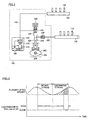
- required supply quantity Qfh at the high-pressure fuel supply system corresponds to the flow rate with which intake failure of high-pressure fuel pump 200 will not occur. That is, required supply quantity Qfh does not depend on the fuel injection quantity, but is proportional to the engine speed as shown in Fig. 6 .
- a set flow rate (discharge quantity) Qp of low-pressure fuel pump 170 is determined in accordance with the sum of required supply quantity Qfl at the low-pressure fuel supply system obtained in step S100 and required supply quantity Qfh at the high-pressure fuel supply system obtained in step S110 (step S120).
- engine ECU 300 transmits a control signal to low-pressure fuel pump 170 to make it discharge the fuel at the set flow rate Qp.
- step S100, step S110 and step S120 correspond respectively to the "first calculating means", the “second calculating means” and the “third calculating means” of the present invention.
- the required supply quantities to the low-pressure fuel supply system and the high-pressure fuel supply system are calculated in accordance with the operation conditions of engine 10, and the flow rate of the low-pressure fuel pump is set in accordance with their sum. Therefore, it is possible to prevent insufficient fuel supply to the respective fuel injection systems, and avoid an increase of power consumption in low-pressure fuel pump 170 due to excessive fuel supply, to thereby improve fuel efficiency. Further, the required supply quantities to the low-pressure fuel supply system and the high-pressure fuel supply system can readily be calculated using the expressions (1) and (3), respectively.
- required supply quantity Qfl at the low-pressure fuel supply system is calculated reflecting DI ratio r.
- DI ratio r For setting DI ratio r, a two-dimensional map of engine speed and load factor, as shown in Fig. 7A , is referred to, and DI ratio r is selectively set from map values r (0, 0) to r (m, n) in accordance with the operation conditions of engine 10 at that time point.
- total fuel injection quantity Qinj# is selectively set in accordance with the operation conditions of engine 10 at that time point, from map values Qinj# (0, 0) to Qinj# (m, n) on a two-dimensional map of engine speed and load factor as shown in Fig. 7B .
- the maps of Figs. 7A and 7B may be combined to generate a two-dimensional map of engine speed and load factor concerning the required supply quantity Qfl at the low-pressure fuel supply system indicated by the expression (1).
- a map related to the engine speed can be generated for the required supply quantity Qfh at the high-pressure fuel supply system.
- the two-dimensional map of engine speed and load factor can be generated for flow rate Qp of the low-pressure fuel pump by combining the processes in steps S100 to S120. That is, flow rate Qp of the low-pressure fuel pump may be set by referring to the map shown in Fig.
- map values Qp (0, 0) to Qp (m, n) in accordance with the operation conditions (engine speed and load factor) of engine 10 at that time point.
- Figs. 8 and 9 illustrate a first example of DI ratio setting maps in the engine system shown in Fig. 1 .
- Figs. 8 and 9 are stored in ROM 320 of engine ECU 300.
- Fig. 8 is the map for a warm state of engine 10
- Fig. 9 is the map for a cold state of engine 10.
- DI ratio r is defined for each operation region that is determined by the engine speed and the load factor of engine 10, individually in the map for the warm state and the map for the cold state.
- the maps are configured to indicate different control regions of in-cylinder injector 110 and intake manifold injector 120 as the temperature of engine 10 changes.
- the map for the warm state shown in Fig. 8 is selected; otherwise, the map for the cold state shown in Fig. 9 is selected.
- One or both of in-cylinder injector 110 and intake manifold injector 120 are controlled based on the selected map and according to the engine speed and the load factor of engine 10.
- NE(1) is set to 2500 rpm to 2700 rpm
- KL(1) is set to 30% to 50%
- KL(2) is set to 60% to 90%
- NE(3) is set to 2900 rpm to 3100 rpm. That is, NE(1) ⁇ NE(3).
- NE(2) in Fig. 8 as well as KL(3) and KL(4) in Fig. 9 are also set as appropriate.
- NE(3) of the map for the cold state shown in Fig. 9 is greater than NE(1) of the map for the warm state shown in Fig. 8 .
- NE(3) of the map for the cold state shown in Fig. 9 is greater than NE(1) of the map for the warm state shown in Fig. 8 .
- the control region of intake manifold injector 120 is expanded to include the region of higher engine speed. That is, in the case where engine 10 is cold, deposits are unlikely to accumulate in the injection hole of in-cylinder injector 110 (even if the fuel is not injected from in-cylinder injector 110).
- the region where the fuel injection is to be carried out using intake manifold injector 120 can be expanded, to thereby improve homogeneity.
- the engine speed and the load of engine 10 are high, ensuring a sufficient intake air quantity, so that it is readily possible to obtain a homogeneous air-fuel mixture using in-cylinder injector 110 alone.
- the fuel injected from in-cylinder injector 110 is atomized within the combustion chamber involving latent heat of vaporization (or, absorbing heat from the combustion chamber).
- the temperature of the air-fuel mixture is decreased at the compression end, whereby antiknock performance is improved.
- intake efficiency improves, leading to high power output.
- in-cylinder injector 110 In the map for the warm state in Fig. 8 , fuel injection is also carried out using only in-cylinder injector 110 when the load factor is KL(1) or less. This shows that in-cylinder injector 110 alone is used in a predetermined low load region when the temperature of engine 10 is high. When engine 10 is in the warm state, deposits are likely to accumulate in the injection hole of in-cylinder injector 110. However, when fuel injection is carried out using in-cylinder injector 110, the temperature of the injection hole can be lowered, whereby accumulation of deposits is prevented. Further, clogging of in-cylinder injector 110 may be prevented while ensuring the minimum fuel injection quantity thereof. Thus, in-cylinder injector 110 alone is used in the relevant region.
- in-cylinder injector 110 is controlled to carry out stratified charge combustion.
- stratified charge combustion By causing the stratified charge combustion during the catalyst warm-up operation, warming up of the catalyst is promoted, and exhaust emission is thus improved.
- Figs. 10 and 11 show a second example of the DI ratio setting maps in the engine system shown in Fig. 1 .
- the fuel injected from in-cylinder injector 110 is atomized within the combustion chamber involving latent heat of vaporization (by absorbing heat from the combustion chamber). Accordingly, the temperature of the air-fuel mixture is decreased at the compression end, and thus, the antiknock performance improves. Further, with the temperature of the combustion chamber decreased, intake efficiency improves, leading to high power output.
- DI ratio settings in the other regions in the setting maps of Figs. 10 and 11 are similar to those of Fig. 8 (warm state) and Fig. 9 (cold state), and thus, detailed description thereof will not be repeated.
- homogeneous combustion is achieved by setting the fuel injection timing of in-cylinder injector 110 in the intake stroke, while stratified charge combustion is realized by setting it in the compression stroke. That is, when the fuel injection timing of in-cylinder injector 110 is set in the compression stroke, a rich air-fuel mixture can be established locally around the spark plug, so that a lean air-fuel mixture in the combustion chamber as a whole is ignited to realize the stratified charge combustion. Even if the fuel injection timing of in-cylinder injector 110 is set in the intake stroke, stratified charge combustion can be realized if it is possible to provide a rich air-fuel mixture locally around the spark plug.
- the stratified charge combustion includes both the stratified charge combustion and semi-stratified charge combustion.
- intake manifold injector 120 injects fuel in the intake stroke to generate a lean and homogeneous air-fuel mixture in the whole combustion chamber, and then in-cylinder injector 110 injects fuel in the compression stroke to generate a rich air-fuel mixture locally around the spark plug, so as to improve the combustion state.
- Such semi-stratified charge combustion is preferable in the catalyst warm-up operation for the following reasons. In the catalyst warm-up operation, it is necessary to considerably retard the ignition timing and maintain a favorable combustion state (idle state) so as to cause a high-temperature combustion gas to reach the catalyst. Further, a certain quantity of fuel needs to be supplied.
- the above-described semi-stratified charge combustion is preferably employed in the catalyst warm-up operation, although either of stratified charge combustion and semi-stratified charge combustion may be employed.
- the fuel injection timing of in-cylinder injector 110 is set in the intake stroke in a basic region corresponding to the almost entire region (here, the basic region refers to the region other than the region where semi-stratified charge combustion is carried out with fuel injection from intake manifold injector 120 in the intake stroke and fuel injection from in-cylinder injector 110 in the compression stroke, which is carried out only in the catalyst warm-up state).
- the fuel injection timing of in-cylinder injector 110 may be set temporarily in the compression stroke for the purpose of stabilizing combustion, for the following reasons.
- the air-fuel mixture is cooled by the injected fuel while the temperature in the cylinder is relatively high. This improves the cooling effect and, hence, the antiknock performance. Further, when the fuel injection timing of in-cylinder injector 110 is set in the compression stroke, the time from the fuel injection to the ignition is short, which ensures strong penetration of the injected fuel, so that the combustion rate increases. The improvement in antiknock performance and the increase in combustion rate can prevent variation in combustion, and thus, combustion stability is improved.
- low-pressure fuel pump 170 is shared by the low-pressure fuel supply system and the high-pressure fuel supply system, and the fuel once drawn by high-pressure fuel pump 200 is discharged back to low-pressure fuel path 190 during the valve-opening period of electromagnetic spill valve 250, which may cause variation in fuel pressure in the low-pressure fuel system.
- the second embodiment a configuration capable of preventing such variation in fuel pressure in the low-pressure fuel supply system will be explained.
- the fuel supply apparatus includes a fuel supply system 151, intake manifold injectors 120 and low-pressure delivery pipes 160a, 160b, and in-cylinder injectors 110 and high-pressure delivery pipes 130a, 130b.
- In-cylinder injectors 110 are divided into groups and arranged in banks a and b
- intake manifold injectors 120 are also divided into groups and arranged in banks a and b.
- high-pressure delivery pipes 130a, 130b and low-pressure delivery pipes 160a, 160b are arranged independently for the respective banks.
- high-pressure fuel pumps 200a and 200b are provided for banks a and b, respectively, independently from each other.
- low-pressure fuel pump 170 is provided commonly for banks a and b.
- High-pressure fuel pumps 200a and 200b each have the configuration and operation similar to those of high-pressure fuel pump 200 shown in Fig. 2 . That is, high-pressure fuel pumps 200a, 200b each draw the fuel delivered from low-pressure fuel pump 170 via low-pressure fuel path 190 and gallery 245 into high-pressure pump chamber 230 in the intake stroke. In the discharge stroke, high-pressure fuel pumps 200a, 200b respectively deliver the pressurized fuel via high-pressure fuel paths 260a, 260b to high-pressure delivery pipes 130a, 130b during the valve-closed period of electromagnetic spill valve 250, and discharge the fuel within high-pressure pump chamber 230 back to low-pressure fuel path 190 via gallery 245 during the valve-opening period of electromagnetic spill valve 250.
- fuel supply system 151 the intake sides of high-pressure fuel pumps 200a and 200b, i.e., galleries 245 are connected by a connecting pipe 270. Further, flow rate adjusting valves 280a and 280b serving as the "flow rate regulating means" are provided in low-pressure fuel path 190, on the routes between connecting pipe 270 and low-pressure delivery pipes 160a and 160b, respectively.
- flow rate at flow rate adjusting valves 280a, 280b When the flow rate at flow rate adjusting valves 280a, 280b is set smaller than that of connecting pipe 270, variation in pressure at connecting pipe 270 due to the fuel discharged back from high-pressure fuel pumps 200a, 200b can be prevented from being transferred to low-pressure delivery pipes 160a, 160b.
- Flow rate adjusting valves 280a, 280b may be replaced with small-diameter portions having the diameter smaller than that of connecting pipe 270.
- the flow rate of flow rate adjusting valves 280a, 280b, or the diameter of the small-diameter portions should be set so as not to cause pressure loss with respect to the intake flow rate of high-pressure fuel pumps 200a, 200b.
- high-pressure fuel pumps 200a and 200b operate in opposite phases from each other. Specifically, during the discharge stroke of high-pressure fuel pump 200a, high-pressure fuel pump 200b operates in the intake stroke. Conversely, during the discharge stroke of high-pressure fuel pump 200b, high-pressure fuel pump 200a operates in the intake stroke. As such, the fuel discharged from one of the high-pressure fuel pumps to low-pressure fuel path 190 during the discharge stroke is guided via connecting pipe 270 to gallery 245 of the other high-pressure fuel pump that is in the intake stroke, without causing variation in fuel pressure with respect to low-pressure delivery pipes 160a, 160b.
- the fuel flowing reversely from high-pressure fuel pumps 200a, 200b to low-pressure fuel path 190 during the discharge stroke would not cause variation in fuel pressure to low-pressure delivery pipes 160a, 160b. Accordingly, it is possible to suppress variation in fuel pressure in the low-pressure supply system, to thereby stabilize fuel injection from intake manifold injectors 120.
- discharge-back fuel the fuel (hereinafter, also referred to as “discharge-back fuel”) discharged back from one high-pressure fuel pump in its discharge stroke (during the valve-opening period of electromagnetic spill valve 250) can be used as the fuel drawn into the other high-pressure fuel pump in its intake stroke.
- the fuel supply quantity from low-pressure fuel pump 170 can be reduced by the quantity of the discharge-back fuel.
- the relevant quantity Qbk of the discharge-back fuel can be obtained based on the fuel injection quantity from in-cylinder injector 110 that is indicated by the product of total fuel injection quantity Qinj# and DI ratio r.
- Qfh kp • Neg - Qbk
- Figs. 14 and 15 show a second configuration example of the fuel supply apparatus according to the second embodiment f the present invention.
- the fuel supply apparatus includes a fuel supply system 152, intake manifold injectors 120 and low-pressure delivery pipes 160a, 160b, and in-cylinder injectors 110 and high-pressure delivery pipes 130a, 130b.
- Fuel supply system 152 differs from fuel supply system 151 shown in Figs. 10 and 11 in the manner of connection between low-pressure delivery pipes 160a, 160b and low-pressure fuel path 190. Otherwise, the configuration of fuel supply system 152 is similar to that of fuel supply system 151, and thus, detailed description thereof will not be repeated.
- low-pressure fuel paths 195a, 195b between connecting pipe 270 and low-pressure delivery pipes 160a, 160b are not directly connected to low-pressure fuel path 190 receiving the discharged fuel from low-pressure fuel pump 170, but connected via flow rate adjusting valves 280a, 280b serving as the "flow rate regulating means".
- the intake fuel quantity of each of high-pressure fuel pumps 200a, 200b is greater than the fuel injection quantity from intake manifold injectors 120.
- the pipe diameters of low-pressure fuel path 190 and connecting pipe 270 are set to be greater than those of low-pressure fuel paths 195a, 195b so as not to cause pressure loss with respect to suction of high-pressure fuel pumps 200a, 200b.
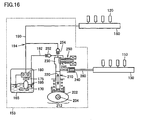
- Fig. 16 shows a third configuration example of the fuel supply apparatus according to the second embodiment of the present invention.
- the fuel supply apparatus includes a fuel supply system 153, intake manifold injectors 120 and a low-pressure delivery pipe 160, and in-cylinder injectors 110 and a high-pressure delivery pipe 130.
- Fuel supply system 153 differs from fuel supply system 150 shown in Fig. 2 in that it includes a high-pressure fuel pump 212 instead of high-pressure fuel pump 200.
- the arrangement and operations of the low-pressure fuel pump and the low-pressure fuel supply system are similar to those in fuel supply system 150, and thus, detailed description thereof will not be repeated.
- a check valve 254 preventing reverse flow of the fuel from high-pressure pump chamber 230 to low-pressure fuel path 190 is provided on a route along which fuel is drawn from low-pressure fuel pump 170 via low-pressure fuel path 190 and a branch point 194 to high-pressure pump chamber 230. Further, a fuel discharge-back route 192 for discharging back the fuel from high-pressure pump chamber 230 via gallery 245 is provided, and a check valve 252 is provided on fuel discharge-back route 192.
- Fuel discharge-back route 192 is provided between high-pressure pump chamber 230 and a fuel discharge-back position 195 in low-pressure fuel path 190 that is located sufficiently far from low-pressure delivery pipe 160, so as to prevent the discharge-back fuel from causing variation in fuel pressure to low-pressure delivery pipe 160.
- fuel discharge-back route 192 is provided as the route extending from high-pressure pump chamber 230 to fuel tank 165. That is, fuel discharge-back position 195 is set in fuel tank 165. Otherwise, the configuration of high-pressure fuel pump 212 is similar to that of high-pressure fuel pump 200.
- high-pressure fuel pump 212 the fuel is drawn from low-pressure fuel path 190 to high-pressure pump chamber 230 via check valve 254 during the intake stroke.
- the fuel pressurized during the valve-closed period of the electromagnetic spill valve is delivered via check valve 240 to high-pressure fuel path 260 as in the case of high-pressure fuel pump 200, during the valve-opening period of the electromagnetic spill valve, the fuel discharged back from high-pressure pump chamber 230 is returned to fuel tank 165 via check valve 252 and fuel discharge-back route 192.
- the discharge-back fuel from high-pressure fuel pump 212 in the discharge stroke is returned to the fuel route sufficiently far from low-pressure delivery pipe 160, preferably to fuel tank 165.
- This can prevent occurrence of variation in fuel pressure in the low-pressure fuel supply system due to the discharge-back fuel from high-pressure fuel pump 212. Accordingly, it is possible to stabilize the fuel injection from intake manifold injectors 120.
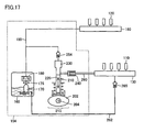
- Fig. 17 is a block diagram illustrating a configuration of the fuel supply apparatus according to a fourth configuration example of the second embodiment of the present invention.
- the fuel supply apparatus includes a fuel supply system 154, intake manifold injectors 120 and a low-pressure delivery pipe 160, and in-cylinder injectors 110 and a high-pressure delivery pipe 130.
- Fuel supply system 154 differs from fuel supply system 150 shown in Fig. 2 in that it includes a high-pressure fuel pump 215 instead of high-pressure fuel pump 200.
- the high-pressure fuel supply system includes a fuel return route 262 from high-pressure delivery pipe 130, and a check valve 265 provided at the relevant fuel route. Check valve 265 opens when the fuel pressure within high-pressure delivery pipe 130 exceeds a prescribed level.
- the arrangement and operations of the low-pressure fuel pump and the low-pressure fuel supply system in fuel supply system 154 are similar to those in fuel supply system 150, and thus, detailed description thereof will not be repeated.
- High-pressure fuel pump 215 differs from high-pressure fuel pump 200 in that electromagnetic spill valve 250 is not provided and in that a check valve 254 is arranged between low-pressure fuel path 190 and high-pressure pump chamber 230. Check valve 254 is arranged so as to prevent the fuel from being discharged from high-pressure pump chamber 23 0 back to low-pressure fuel path 190. Otherwise, the configuration of high-pressure fuel pump 215 is similar to that of high-pressure fuel pump 200.
- high-pressure fuel pump 215 the whole quantity of the fuel drawn from low-pressure fuel path 190 to high-pressure pump chamber 230 in the intake stroke is delivered to high-pressure fuel path 260 in the discharge stroke.
- the excess fuel supplied to high-pressure delivery pipe 130 is returned to fuel tank 165 via check valve 265 and fuel return route 262.
- high-pressure fuel pump 215 having the configuration where the fuel is not discharged back to low-pressure fuel path 190 in the discharge stroke is employed.
- occurrence of variation in fuel pressure in the low-pressure fuel supply system is prevented, and accordingly, fuel injection from intake manifold injectors 120 is stabilized.
- High-pressure fuel pump 215 can be simplified in configuration, since electromagnetic spill valve 155 for which open/close control in accordance with the discharge quantity would be necessary is not provided. However, since the pressurizing (compressing) operation of the fuel is carried out over the entire period of the discharge stroke, engine load becomes high, which is disadvantageous in terms of fuel efficiency.
- Fig. 18 is a block diagram showing a fifth configuration example of the fuel supply apparatus according to the second embodiment of the present invention.
- in-cylinder injectors 110 and intake manifold injectors 120 are each divided into groups to be arranged in banks a and b.
- high-pressure delivery pipes 130a and 130b and low-pressure delivery pipes 160a and 160b are provided for banks a and b, respectively.
- Low-pressure delivery pipes 160a and 160b are branched from low-pressure fuel path 190 at a branch point Nc on low-pressure fuel path 190.
- a common high-pressure fuel pump 200 is provided for high-pressure delivery pipes 130a and 130b. Further, a fuel intake route from low-pressure fuel path 190 to high-pressure fuel pump 200 is branched from low-pressure fuel path 190 at a branch point Na thereon.
- a connecting pipe 270 is provided between high-pressure delivery pipes 130a and 130b, and a relief valve 266 is provided to form a fuel return route from high-pressure delivery pipe 130b to fuel tank 165.
- fuel pressure adjusting devices 290a and 290b are further provided corresponding to low-pressure delivery pipes 160a and 160b, respectively, arranged for the respective banks.
- Fuel pressure adjusting devices 290a, 290b may be pulsation dampers, for example. This can stabilize the fuel pressure in low-pressure delivery pipes 160a, 160b.
- low-pressure delivery pipes 160a, 160b can further be stabilized when flow rate adjusting valves 280a, 280b (not shown) similar to those in Figs. 12-15 are provided between branch point Nc and low-pressure delivery pipes 160a, 160b.
- a pulsation damper 295 is further provided at the intake side of high-pressure fuel pump 200, and the branch point Na from low-pressure fuel path 190 to the intake side of high-pressure fuel pump 200 is provided at a distance from low-pressure delivery pipes 160a, 160b. This ensures a sufficiently long route between the fuel discharge-back point from high-pressure fuel pump 200 and low-pressure delivery pipes 160a, 160b. Accordingly, variation in fuel pressure in the low-pressure fuel supply system due to the fuel discharged back from high-pressure fuel pump 200 can further be suppressed.
- fuel tank 165 and low-pressure fuel pump 170 are provided on the side of rear wheels 500b, and branch point Na is provided near the outlet of fuel tank 165.
- High-pressure fuel pump 200 and the high-pressure fuel supply system (not shown) at the subsequent stage, and low-pressure delivery pipes 160a, 160b in the low-pressure fuel supply system are provided corresponding to engine 10 arranged near front wheels 500a.
- the configuration for ensuring the sufficiently long route between high-pressure fuel pump 200 and low-pressure delivery pipes 160a, 160b the configuration of arranging the fuel pipes at both the right and left sides of the vehicle, the configuration of arranging the fuel pipes only at the right side or the left side, or the configuration of providing the pipes in a spiral manner to ensure a long pipe length while setting branch point Na near engine 10, may be applied.
- the configuration of providing an accumulator or a reservoir in the vicinity of the fuel discharge-back point from high-pressure fuel pump 200 so as to attenuate pulsation due to the discharge-back fuel may be provided to further suppress variation in fuel pressure in the low-pressure fuel supply system.
- the present invention is applicable to fuel supply to an internal combustion engine of an automobile.
Landscapes
- Engineering & Computer Science (AREA)
- Chemical & Material Sciences (AREA)
- Combustion & Propulsion (AREA)
- Mechanical Engineering (AREA)
- General Engineering & Computer Science (AREA)
- Fuel-Injection Apparatus (AREA)
- Electrical Control Of Air Or Fuel Supplied To Internal-Combustion Engine (AREA)
- Combined Controls Of Internal Combustion Engines (AREA)
Claims (8)
- Kraftstoffzuführvorrichtung zum Zuführen eines Kraftstoffs zu einem Verbrennungsmotor (10), aufweisend:eine erste Kraftstoffpumpe (170), die einen Kraftstoff aus einem Kraftstofftank (165) ansaugt und den Kraftstoff bei einem ersten Druck abführt;ein erstes Kraftstoffzuführsystem, das erste Kraftstoffeinspritzeinrichtungen (120) zum Einspritzen eines Kraftstoffs in den Verbrennungsmotor (10) bei dem ersten Druck und eine erste Kraftstoffzuführleitung (160) beinhaltet, die den von der ersten Kraftstoffpumpe (170) abgeführten Kraftstoff empfängt und den Kraftstoff zu den ersten Kraftstoffeinspritzeinrichtungen (120) liefert;ein zweites Kraftstoffzuführsystem, das zweite Kraftstoffeinspritzeinrichtungen (110) zum Einspritzen eines Kraftstoffs in den Verbrennungsmotor (10) bei einem zweiten Druck, der höher ist als der erste Druck, eine zweite Kraftstoffpumpe (200), die durch den Verbrennungsmotor (10) angetrieben wird und den Kraftstoff, der von der ersten Kraftstoffpumpe (170) abgeführt wird, ansaugt und weiter unter Druck setzt und den Kraftstoff bei dem zweiten Druck abführt, und eine zweite Kraftstoffzuführleitung (130) beinhaltet, die den Kraftstoff, der von der zweiten Kraftstoffpumpe (200) abgeführt wird, empfängt und den Kraftstoff zu den zweiten Kraftstoffeinspritzeinrichtungen (110) abführt; undeine Abführmengen-Berechnungseinrichtung (S100-S120) zum Erhalten von Soll-Zuführmengen (Qfl, Qfh) zu jeweils dem ersten und zweiten Kraftstoffzuführsystem gemäß einer Betriebsbedingung des Verbrennungsmotors (10) und zum Bestimmen einer Abführmenge (Qp) von der ersten Kraftstoffpumpe (170) basierend auf den erhaltenen Soll-Zuführmengen (Qfl, Qfh), die erhalten werden, wobeidie Abführmengen-Berechnungseinrichtung (S 100-S 120) beinhaltet:eine erste Berechnungseinrichtung (S100) zum Berechnen der Soll-Zuführmenge (Qfl) zu dem ersten Kraftstoffzuführsystem basierend auf zumindest einer Kraftstoffeinspritzmenge (Qinjp#) durch die ersten Kraftstoffeinspritzeinrichtungen (120) und der Anzahl der Umdrehungen (Neg) des Verbrennungsmotors (10),eine zweite Berechnungseinrichtung (S 110) zum Berechnen der Soll-Zuführmenge (Qfh) zu dem zweiten Kraftstoffzuführsystem basierend auf zumindest der Anzahl von Umdrehungen (Neg) des Verbrennungsmotors (10) ohne die Kraftstoffeinspritzmenge (Qinjp#), undeine dritte Berechnungseinrichtung (S 120) zum Bestimmen der Abführmenge (Qp) von der ersten Kraftstoffpumpe (170) gemäß einer Summe der Soll-Zuführmengen (Qfl, Qfh), die durch die erste und die zweite Berechnungseinrichtung berechnet werden.
- Kraftstoffzuführvorrichtung nach Anspruch 1, die ferner eine Kraftstoffeinspritzsteuerungseinrichtung (300) zum Steuern eines Kraftstoffeinspritzverhältnisses (r) zwischen den ersten Kraftstoffeinspritzeinrichtungen (120) und den zweiten Kraftstoffeinspritzeinrichtungen (110) in Bezug auf eine Gesamt-Kraftstoffeinspritzmenge(Qinj') gemäß einem Betriebszustand des Verbrennungsmotors (10) aufweist, wobei
die erste Berechnungseinrichtung (S 100) die Soll-Zuführmenge (Qfl) zu dem ersten Kraftstoffzuführsystem berechnet, indem die Kraftstoffeinspritzmenge (Qinjp#) der ersten Kraftstoffeinspritzeinrichtungen (120) erhalten wird, die das Kraftstoffeinspritzverhältnis (r) reflektiert, das durch die Kraftstoffeinspritzsteuerungseinrichtung (300) gesteuert wird. - Kraftstoffzuführvorrichtung nach Anspruch 1, wobei
eine Mehrzahl der zweiten Kraftstoffzuführleitungen (130a, 130b) bereitgestellt sind,
wobei die zweiten Kraftstoffeinspritzeinrichtungen (110) in Gruppen aufgeteilt sind und jeweils für die Mehrzahl der zweiten Kraftstoffzuführleitungen (130a, 130b) bereitgestellt sind,
eine Mehrzahl der zweiten Kraftstoffpumpen (200a, 200b) jeweils für die Mehrzahl der zweiten Kraftstoffzuführleitungen (130a, 130b) bereitgestellt sind, und
in einer jeweiligen der zweiten Kraftstoffzuführpumpen (200a, 200b) ein Plunger (220) in einem Zylinder angetrieben wird, um sich durch einen Nocken (202), der durch den Verbrennungsmotor (10) drehend angetrieben wird, hin- und herzubewegen, und in einem Einlasshub, wo die Volumenkapazität einer Druckkammer (230), die durch den Zylinder und den Plunger begrenzt wird, vergrößert wird, der Kraftstoff von einer Einlassseite der zweiten Kraftstoffpumpe (200), die mit einer Abführseite der ersten Kraftstoffpumpe (170) verbunden ist, in die Unterdrucksetzungskammer (230) gesogen wird, und in einem Auslasshub, wo die Volumenkapazität der Unterdrucksetzungskammer (230) reduziert wird, der Kraftstoff während einer Ventilschließdauer eines Dosierventils (250) von der Unterdrucksetzungskammer (230) zu einer Abführroute abgeführt wird und während einer Ventilöffnungsdauer des Dosierventils (250) der Kraftstoff in umgekehrter Richtung von der Unterdrucksetzungskammer (230) zur Einlassseite strömt,
wobei die Kraftstoffzuführvorrichtung ferner aufweist:einen Verbindungsweg (270), der die Einlassseiten der Mehrzahl der zweiten Kraftstoffpumpen (200a, 200b) verbindet; andeine Strömungsraten-Regulierungseinrichtung (280a, 280b), die auf einer Kraftstoffroute zwischen dem Verbindungsweg (270) und der ersten Kraftstoffzuführleitung (160a, 160b) angeordnet ist. - Kraftstoffzuführvorrichtung nach Anspruch 3, wobei die zweiten Kraftstoffzuführpumpen (200a, 200b), bei denen die Einlassseiten durch den Verbindungsweg (270) miteinander verbunden sind, derart angeordnet sind, dass eine der zweiten Kraftstoffpumpen (200a, 200b) im Einlasshub arbeitet, wenn die andere der zweiten Kraftstoffpumpen (200a, 200b) im Auslasshub arbeitet.
- Kraftstoffzuführvorrichtung nach Anspruch 1, wobei
in der zweiten Kraftstoffpumpe (212) ein Plunger (220) in einem Zylinder angetrieben wird, um sich durch einen Nocken (202), der durch den Verbrennungsmotor (10) drehend angetrieben wird, hin- und herzubewegen, und in einem Einlasshub, wo die Volumenkapazität einer Unterdrucksetzungskammer (230), die durch den Zylinder und den Plunger (220) begrenzt wird, vergrößert wird, der Kraftstoff zur Unterdrucksetzungskammer (230) von einer Einlassseite der zweiten Kraftstoffpumpe (212), die mit einer Abführseite der ersten Kraftstoffpumpe (170) über einen Abzweigpunkt (194) verbunden ist, gesogen wird und in einem Auslasshub, in dem die Volumenkapazität der Unterdrucksetzungskammer (230) reduziert wird, der Kraftstoff während einer Ventilschließdauer eines Dosierventils (250) von der Unterdrucksetzungskammer (230) an eine Abführroute abgeführt wird und der Kraftstoff während einer Ventilöffnungsdauer des Dosierventils (250) in umgekehrter Richtung von der Unterdrucksetzungsammer (230) zur Einlassseite strömt,
die Kraftstoffzuführvorrichtung ferner eine Einrichtung (192) zum zurück erfolgenden Abführen des Kraftstoffs aufweist, um den Kraftstoff, der in umgekehrter Richtung von der Unterdrucksetzungskammer (230) strömt, zur Einlassseite in der zweiten Kraftstoffpumpe (200) im Auslasshub zu einer Position (195), zu der die Abführung des Kraftstoffs zurück erfolgt und die in dem ersten Kraftstoffzuführsystem angeordnet ist, zu führen, wobei
der Abzweigpunkt (194) an einer Position angeordnet ist, die sich von dem Kraftstofftank (165) weiter weg befindet als zumindest die Position (195), zu der die Abführung des Kraftstoffs zurück erfolgt. - Kraftstoffzuführvorrichtung nach Anspruch 1, wobei
in der zweiten Kraftstoffpumpe (215) ein Plunger (220) in einem Zylinder angetrieben wird, um sich durch einen Nocken (202), der durch den Verbrennungsmotor (10) drehend angetrieben wird, hin- und herzubewegen, und in einem Einlasshub, wo die Volumenkapazität einer Unterdrucksetzungskammer (230), die durch den Zylinder und den Plunger (220) begrenzt wird, vergrößert wird, der Kraftstoff von einer Einlassseite der zweiten Kraftstoffpumpe (200), die mit einer Abführseite der ersten Kraftstoffpumpe (170) verbunden ist, in die Unterdrucksetzungskammer (230) gesogen wird, und in einem Auslasshub, wo die Volumenkapazität der Unterdrucksetzungskammer (230) reduziert wird, der unter Druck gesetzte Kraftstoff von der Unterdrucksetzungskammer (230) zu einer Abführroute abgeführt wird,
wobei die Kraftstoffzuführvorrichtung ferner eine Kraftstoffrückführeinrichtung (262, 265) aufweist, die betätigt wird, wenn ein Kraftstoffdruck in der zweiten Kraftstoffzuführleitung (130) einen vorgeschriebenen Wert überschreitet, um eine Kraftstoffrückführroute (262) von der zweiten Kraftstoffzuführleitung (130) zum Kraftstofftank (165) auszubilden. - Kraftstoffzuführvorrichtung nach Anspruch 1, wobei
eine Mehrzahl der ersten Kraftstoffzuführleitungen (160a, 160b) bereitgestellt ist,
die ersten Kraftstoffeinspritzeinrichtungen (120) in Gruppen aufgeteilt und jeweils für die Mehrzahl der ersten Kraftstoffzuführleitungen (160a, 160b) bereitgestellt sind, und
die erste Kraftstoffpumpe (170) für die Mehrzahl der ersten Kraftstoffzuführleitungen (160a, 160b) gemeinsam bereitgestellt ist,
die erste Kraftstoffzuführvorrichtung ferner Druckeinstellungsvorrichtungen (290a, 290b) aufweist, die jeweils für die Mehrzahl der ersten Kraftstoffzuführleitungen (160a, 160b) bereitgestellt sind. - Kraftstoffzuführvorrichtung nach Anspruch 1, wobei
die Soll-Zuführmenge (Qfh) berechnet wird basierend auf einem Ausdruck
wobei Qfh die Soll-Zuführmenge zum zweiten Kraftstoffzuführsystem darstellt, kp eine Konstante darstellt, die durch ein Produkt aus der Volumenkapazität einer Kammer (230) der zweiten Kraftstoffpumpe (200) und der Anzahl der Male der Kraftstoffabführung von der zweiten Kraftstoffpumpe (200) pro Motorumdrehung gezeigt ist, und Neg die Anzahl der Umdrehungen (Neg) des Verbrennungsmotors (10) darstellt.
Applications Claiming Priority (2)
| Application Number | Priority Date | Filing Date | Title |
|---|---|---|---|
| JP2004334444A JP4466340B2 (ja) | 2004-11-18 | 2004-11-18 | 燃料供給装置 |
| PCT/JP2005/021201 WO2006054677A1 (en) | 2004-11-18 | 2005-11-14 | Fuel supply apparatus |
Publications (2)
| Publication Number | Publication Date |
|---|---|
| EP1812704A1 EP1812704A1 (de) | 2007-08-01 |
| EP1812704B1 true EP1812704B1 (de) | 2009-03-25 |
Family
ID=35559370
Family Applications (1)
| Application Number | Title | Priority Date | Filing Date |
|---|---|---|---|
| EP05806619A Expired - Lifetime EP1812704B1 (de) | 2004-11-18 | 2005-11-14 | Kraftstoffzufuhrvorrichtung |
Country Status (6)
| Country | Link |
|---|---|
| US (1) | US7464696B2 (de) |
| EP (1) | EP1812704B1 (de) |
| JP (1) | JP4466340B2 (de) |
| CN (1) | CN100529372C (de) |
| DE (1) | DE602005013562D1 (de) |
| WO (1) | WO2006054677A1 (de) |
Cited By (2)
| Publication number | Priority date | Publication date | Assignee | Title |
|---|---|---|---|---|
| JP2011094610A (ja) * | 2009-10-28 | 2011-05-12 | Hitachi Ltd | 高圧燃料供給ポンプと燃料供給システム |
| US12085216B2 (en) | 2022-02-17 | 2024-09-10 | Arctic Cat Inc. | Multi-use fuel filler tube |
Families Citing this family (35)
| Publication number | Priority date | Publication date | Assignee | Title |
|---|---|---|---|---|
| JP3894179B2 (ja) * | 2003-10-02 | 2007-03-14 | トヨタ自動車株式会社 | 内燃機関の燃料供給装置 |
| EP1763631A2 (de) * | 2004-07-02 | 2007-03-21 | Toyota Jidosha Kabushiki Kaisha | Kraftstoffzufuhrsystem für verbrennungsmotor |
| JP2006258039A (ja) * | 2005-03-18 | 2006-09-28 | Toyota Motor Corp | 内燃機関の燃料供給装置 |
| JP4297160B2 (ja) | 2006-12-22 | 2009-07-15 | トヨタ自動車株式会社 | 内燃機関 |
| DE102006062491A1 (de) * | 2006-12-28 | 2008-07-03 | Robert Bosch Gmbh | Vorrichtung zur Dosierung von Kraftstoff zum Abgassystem eines Verbrennungsmotors |
| JP4172524B1 (ja) * | 2007-04-24 | 2008-10-29 | トヨタ自動車株式会社 | 車両およびその制御方法 |
| JP4669066B2 (ja) * | 2007-05-29 | 2011-04-13 | エムエーエヌ・ディーゼル・アンド・ターボ・フィリアル・アフ・エムエーエヌ・ディーゼル・アンド・ターボ・エスイー・ティスクランド | 大型2サイクルディーゼルエンジン用の燃料噴射システム |
| FR2920038A1 (fr) * | 2007-08-14 | 2009-02-20 | Renault Sas | Systeme d'injection de carburant pour moteur a combustion interne |
| US7448361B1 (en) * | 2007-10-23 | 2008-11-11 | Ford Global Technologies, Llc | Direct injection fuel system utilizing water hammer effect |
| US7867433B2 (en) * | 2008-05-30 | 2011-01-11 | Exxonmobil Chemical Patents Inc. | Polyolefin-based crosslinked articles |
| US8765832B2 (en) | 2011-10-14 | 2014-07-01 | Exxonmobil Chemical Patents Inc. | Polyolefin-based crosslinked compositions and methods of making them |
| DE102008043217A1 (de) * | 2008-10-28 | 2010-04-29 | Robert Bosch Gmbh | Kraftstoff-Hochdruckpumpe für eine Brennkraftmaschine |
| JP5056729B2 (ja) * | 2008-11-13 | 2012-10-24 | トヨタ自動車株式会社 | 内燃機関の燃料供給装置 |
| US8975334B2 (en) * | 2009-07-23 | 2015-03-10 | Exxonmobil Chemical Patents Inc. | Crosslinkable propylene-based copolymers, methods for preparing the same, and articles made therefrom |
| US8742019B2 (en) | 2009-10-02 | 2014-06-03 | Exxonmobil Chemical Patents Inc. | Crosslinked polyolefin polymer blends |
| DE102010003209A1 (de) * | 2010-03-24 | 2011-09-29 | Robert Bosch Gmbh | Verfahren und Vorrichtung zur Anpassung von Adaptionswerten für die Ansteuerung von Einspritzventilen in einem Motorsystem mit mehreren Einspritzungsarten |
| DE102010061810A1 (de) | 2010-11-23 | 2012-05-24 | Robert Bosch Gmbh | Verfahren zum Betreiben eines Kraftstoffsystems einer Brennkraftmaschine |
| JP5672180B2 (ja) * | 2011-07-12 | 2015-02-18 | トヨタ自動車株式会社 | 燃料供給システムの制御装置 |
| DE112011105711B4 (de) * | 2011-10-06 | 2019-05-23 | Toyota Jidosha Kabushiki Kaisha | Steuervorrichtung für Maschine mit interner Verbrennung |
| GB2500889A (en) * | 2012-04-02 | 2013-10-09 | Gm Global Tech Operations Inc | Method of operating a fuel injection system which corrects for pump efficiency and injector performance |
| US8781039B2 (en) | 2012-10-26 | 2014-07-15 | Deere & Company | Receiver and method for receiving a composite signal |
| CN103075283B (zh) * | 2012-12-29 | 2015-09-30 | 济南威度电子科技有限公司 | 一种基于液压原理的电控气体喷射系统及喷射方法 |
| JP2014190180A (ja) * | 2013-03-26 | 2014-10-06 | Toyota Motor Corp | 内燃機関の燃料噴射装置 |
| US20140353262A1 (en) * | 2013-05-31 | 2014-12-04 | Carter Fuel Systems, Llc | Self-cleaning fuel pump |
| JP6146365B2 (ja) * | 2014-04-03 | 2017-06-14 | 株式会社デンソー | 燃料供給システム |
| US10428210B2 (en) | 2014-10-29 | 2019-10-01 | Exxonmobil Chemical Patents Inc. | Polyolefin adhesive compositions for elastic applications |
| US10563611B2 (en) | 2014-12-19 | 2020-02-18 | Ford Global Technologies, Llc | Fuel delivery system and method for operation of a fuel delivery system |
| US10323612B2 (en) * | 2015-06-12 | 2019-06-18 | Ford Global Technologies, Llc | Methods and systems for dual fuel injection |
| US11454189B2 (en) * | 2015-06-29 | 2022-09-27 | Ford Global Technologies, Llc | Methods and systems for port fuel injection control |
| DE102015016925A1 (de) * | 2015-12-24 | 2017-06-29 | Audi Ag | Kraftstoffpumpe |
| GB2549140A (en) * | 2016-04-08 | 2017-10-11 | Delphi Int Operations Luxembourg Sarl | Fuel injection equipment and control method |
| DK179576B1 (en) * | 2017-07-13 | 2019-02-20 | Nel Hydrogen A/S | A method of controlling the hydraulic fluid pressure of a diaphragm compressor |
| US10450992B2 (en) * | 2017-10-30 | 2019-10-22 | Stanadyne Llc | GDI pump with direct injection and port injection |
| JP7102755B2 (ja) * | 2018-02-02 | 2022-07-20 | マツダ株式会社 | エンジンの燃料供給装置 |
| US11268482B2 (en) | 2020-04-21 | 2022-03-08 | Caterpillar Inc. | Fuel system having pumping and filtration fuel module and flow housing for same |
Family Cites Families (8)
| Publication number | Priority date | Publication date | Assignee | Title |
|---|---|---|---|---|
| JP3175426B2 (ja) | 1993-10-06 | 2001-06-11 | トヨタ自動車株式会社 | 内燃機関の燃料噴射装置 |
| JPH10318071A (ja) | 1997-05-21 | 1998-12-02 | Aisan Ind Co Ltd | 燃料ポンプ制御装置 |
| ES2206278T3 (es) | 1999-06-25 | 2004-05-16 | Bayer Aktiengesellschaft | Derivados de piperazinona que presental grupos alcoxisilano. |
| AU2001261245A1 (en) * | 2000-05-08 | 2001-11-20 | Cummins, Inc. | Multiple operating mode engine and method of operation |
| JP4541500B2 (ja) | 2000-05-24 | 2010-09-08 | 富士重工業株式会社 | 筒内燃料噴射エンジンの燃料噴射制御装置 |
| JPWO2003008796A1 (ja) * | 2001-07-16 | 2004-11-11 | 臼井国際産業株式会社 | 燃料圧力脈動抑制システム |
| JP3741087B2 (ja) * | 2002-07-12 | 2006-02-01 | トヨタ自動車株式会社 | 筒内噴射式内燃機関の燃料噴射制御装置 |
| JP3894179B2 (ja) | 2003-10-02 | 2007-03-14 | トヨタ自動車株式会社 | 内燃機関の燃料供給装置 |
-
2004
- 2004-11-18 JP JP2004334444A patent/JP4466340B2/ja not_active Expired - Fee Related
-
2005
- 2005-11-14 WO PCT/JP2005/021201 patent/WO2006054677A1/en not_active Ceased
- 2005-11-14 EP EP05806619A patent/EP1812704B1/de not_active Expired - Lifetime
- 2005-11-14 CN CNB2005800395113A patent/CN100529372C/zh not_active Expired - Fee Related
- 2005-11-14 DE DE602005013562T patent/DE602005013562D1/de not_active Expired - Lifetime
- 2005-11-15 US US11/272,973 patent/US7464696B2/en not_active Expired - Fee Related
Cited By (3)
| Publication number | Priority date | Publication date | Assignee | Title |
|---|---|---|---|---|
| JP2011094610A (ja) * | 2009-10-28 | 2011-05-12 | Hitachi Ltd | 高圧燃料供給ポンプと燃料供給システム |
| US8794936B2 (en) | 2009-10-28 | 2014-08-05 | Hitachi, Ltd. | High-pressure fuel supply pump and fuel supply system |
| US12085216B2 (en) | 2022-02-17 | 2024-09-10 | Arctic Cat Inc. | Multi-use fuel filler tube |
Also Published As
| Publication number | Publication date |
|---|---|
| US20060102149A1 (en) | 2006-05-18 |
| JP2006144628A (ja) | 2006-06-08 |
| WO2006054677A1 (en) | 2006-05-26 |
| CN101061304A (zh) | 2007-10-24 |
| JP4466340B2 (ja) | 2010-05-26 |
| CN100529372C (zh) | 2009-08-19 |
| DE602005013562D1 (de) | 2009-05-07 |
| EP1812704A1 (de) | 2007-08-01 |
| US7464696B2 (en) | 2008-12-16 |
Similar Documents
| Publication | Publication Date | Title |
|---|---|---|
| EP1812704B1 (de) | Kraftstoffzufuhrvorrichtung | |
| US7263972B2 (en) | Fuel supply system for internal combustion engine | |
| US7121261B2 (en) | Fuel supply apparatus for internal combustion engine | |
| US7694507B2 (en) | Control apparatus of internal combustion engine | |
| US7114488B2 (en) | Control apparatus for internal combustion engine | |
| EP1809882B1 (de) | Steuervorrichtung für verbrennungsmotor | |
| EP1907680B1 (de) | Steuervorrichtung für einen verbrennungsmotor | |
| US7913667B2 (en) | Fuel supply apparatus for vehicle | |
| US7213574B2 (en) | Control device for internal combustion engine |
Legal Events
| Date | Code | Title | Description |
|---|---|---|---|
| PUAI | Public reference made under article 153(3) epc to a published international application that has entered the european phase |
Free format text: ORIGINAL CODE: 0009012 |
|
| 17P | Request for examination filed |
Effective date: 20070209 |
|
| AK | Designated contracting states |
Kind code of ref document: A1 Designated state(s): DE FR IT |
|
| DAX | Request for extension of the european patent (deleted) | ||
| RBV | Designated contracting states (corrected) |
Designated state(s): DE FR IT |
|
| 17Q | First examination report despatched |
Effective date: 20080328 |
|
| GRAP | Despatch of communication of intention to grant a patent |
Free format text: ORIGINAL CODE: EPIDOSNIGR1 |
|
| GRAS | Grant fee paid |
Free format text: ORIGINAL CODE: EPIDOSNIGR3 |
|
| GRAA | (expected) grant |
Free format text: ORIGINAL CODE: 0009210 |
|
| AK | Designated contracting states |
Kind code of ref document: B1 Designated state(s): DE FR IT |
|
| REF | Corresponds to: |
Ref document number: 602005013562 Country of ref document: DE Date of ref document: 20090507 Kind code of ref document: P |
|
| PLBE | No opposition filed within time limit |
Free format text: ORIGINAL CODE: 0009261 |
|
| STAA | Information on the status of an ep patent application or granted ep patent |
Free format text: STATUS: NO OPPOSITION FILED WITHIN TIME LIMIT |
|
| 26N | No opposition filed |
Effective date: 20091229 |
|
| REG | Reference to a national code |
Ref country code: DE Ref legal event code: R084 Ref document number: 602005013562 Country of ref document: DE Effective date: 20130829 |
|
| REG | Reference to a national code |
Ref country code: FR Ref legal event code: PLFP Year of fee payment: 11 |
|
| REG | Reference to a national code |
Ref country code: FR Ref legal event code: PLFP Year of fee payment: 12 |
|
| PGFP | Annual fee paid to national office [announced via postgrant information from national office to epo] |
Ref country code: FR Payment date: 20161014 Year of fee payment: 12 Ref country code: DE Payment date: 20161108 Year of fee payment: 12 |
|
| PGFP | Annual fee paid to national office [announced via postgrant information from national office to epo] |
Ref country code: IT Payment date: 20161122 Year of fee payment: 12 |
|
| REG | Reference to a national code |
Ref country code: DE Ref legal event code: R119 Ref document number: 602005013562 Country of ref document: DE |
|
| REG | Reference to a national code |
Ref country code: FR Ref legal event code: ST Effective date: 20180731 |
|
| PG25 | Lapsed in a contracting state [announced via postgrant information from national office to epo] |
Ref country code: DE Free format text: LAPSE BECAUSE OF NON-PAYMENT OF DUE FEES Effective date: 20180602 Ref country code: FR Free format text: LAPSE BECAUSE OF NON-PAYMENT OF DUE FEES Effective date: 20171130 Ref country code: IT Free format text: LAPSE BECAUSE OF NON-PAYMENT OF DUE FEES Effective date: 20171114 |