EP1812154B1 - Mischkammer für einen reformer sowie verfahren zum betreiben derselben - Google Patents
Mischkammer für einen reformer sowie verfahren zum betreiben derselben Download PDFInfo
- Publication number
- EP1812154B1 EP1812154B1 EP05806947.7A EP05806947A EP1812154B1 EP 1812154 B1 EP1812154 B1 EP 1812154B1 EP 05806947 A EP05806947 A EP 05806947A EP 1812154 B1 EP1812154 B1 EP 1812154B1
- Authority
- EP
- European Patent Office
- Prior art keywords
- fuel
- mixing chamber
- zone
- oxidizing agent
- nozzle
- Prior art date
- Legal status (The legal status is an assumption and is not a legal conclusion. Google has not performed a legal analysis and makes no representation as to the accuracy of the status listed.)
- Expired - Lifetime
Links
Images


Classifications
-
- H—ELECTRICITY
- H01—ELECTRIC ELEMENTS
- H01M—PROCESSES OR MEANS, e.g. BATTERIES, FOR THE DIRECT CONVERSION OF CHEMICAL ENERGY INTO ELECTRICAL ENERGY
- H01M8/00—Fuel cells; Manufacture thereof
- H01M8/06—Combination of fuel cells with means for production of reactants or for treatment of residues
- H01M8/0606—Combination of fuel cells with means for production of reactants or for treatment of residues with means for production of gaseous reactants
- H01M8/0612—Combination of fuel cells with means for production of reactants or for treatment of residues with means for production of gaseous reactants from carbon-containing material
- H01M8/0618—Reforming processes, e.g. autothermal, partial oxidation or steam reforming
-
- B—PERFORMING OPERATIONS; TRANSPORTING
- B01—PHYSICAL OR CHEMICAL PROCESSES OR APPARATUS IN GENERAL
- B01J—CHEMICAL OR PHYSICAL PROCESSES, e.g. CATALYSIS OR COLLOID CHEMISTRY; THEIR RELEVANT APPARATUS
- B01J19/00—Chemical, physical or physico-chemical processes in general; Their relevant apparatus
- B01J19/0006—Controlling or regulating processes
- B01J19/002—Avoiding undesirable reactions or side-effects, e.g. avoiding explosions, or improving the yield by suppressing side-reactions
- B01J19/0026—Avoiding carbon deposits
-
- B—PERFORMING OPERATIONS; TRANSPORTING
- B01—PHYSICAL OR CHEMICAL PROCESSES OR APPARATUS IN GENERAL
- B01J—CHEMICAL OR PHYSICAL PROCESSES, e.g. CATALYSIS OR COLLOID CHEMISTRY; THEIR RELEVANT APPARATUS
- B01J19/00—Chemical, physical or physico-chemical processes in general; Their relevant apparatus
- B01J19/24—Stationary reactors without moving elements inside
- B01J19/248—Reactors comprising multiple separated flow channels
- B01J19/2485—Monolithic reactors
-
- B—PERFORMING OPERATIONS; TRANSPORTING
- B01—PHYSICAL OR CHEMICAL PROCESSES OR APPARATUS IN GENERAL
- B01J—CHEMICAL OR PHYSICAL PROCESSES, e.g. CATALYSIS OR COLLOID CHEMISTRY; THEIR RELEVANT APPARATUS
- B01J4/00—Feed or outlet devices; Feed or outlet control devices
- B01J4/001—Feed or outlet devices as such, e.g. feeding tubes
-
- C—CHEMISTRY; METALLURGY
- C01—INORGANIC CHEMISTRY
- C01B—NON-METALLIC ELEMENTS; COMPOUNDS THEREOF; METALLOIDS OR COMPOUNDS THEREOF NOT COVERED BY SUBCLASS C01C
- C01B3/00—Hydrogen; Gaseous mixtures containing hydrogen; Separation of hydrogen from mixtures containing it; Purification of hydrogen; Reversible storage of hydrogen
- C01B3/02—Production of hydrogen; Production of gaseous mixtures containing hydrogen
- C01B3/32—Production of hydrogen; Production of gaseous mixtures containing hydrogen by reaction of gaseous or liquid organic compounds with gasifying agents, e.g. water, carbon dioxide or air
- C01B3/34—Production of hydrogen; Production of gaseous mixtures containing hydrogen by reaction of gaseous or liquid organic compounds with gasifying agents, e.g. water, carbon dioxide or air by reaction of hydrocarbons with gasifying agents
- C01B3/38—Production of hydrogen; Production of gaseous mixtures containing hydrogen by reaction of gaseous or liquid organic compounds with gasifying agents, e.g. water, carbon dioxide or air by reaction of hydrocarbons with gasifying agents using catalysts
- C01B3/382—Processes with two or more reaction steps, of which at least one is catalytic, e.g. steam reforming and partial oxidation
-
- B—PERFORMING OPERATIONS; TRANSPORTING
- B01—PHYSICAL OR CHEMICAL PROCESSES OR APPARATUS IN GENERAL
- B01F—MIXING, e.g. DISSOLVING, EMULSIFYING OR DISPERSING
- B01F25/00—Flow mixers; Mixers for falling materials, e.g. solid particles
- B01F2025/91—Direction of flow or arrangement of feed and discharge openings
- B01F2025/913—Vortex flow, i.e. flow spiraling in a tangential direction and moving in an axial direction
-
- B—PERFORMING OPERATIONS; TRANSPORTING
- B01—PHYSICAL OR CHEMICAL PROCESSES OR APPARATUS IN GENERAL
- B01F—MIXING, e.g. DISSOLVING, EMULSIFYING OR DISPERSING
- B01F23/00—Mixing according to the phases to be mixed, e.g. dispersing or emulsifying
- B01F23/10—Mixing gases with gases
-
- B—PERFORMING OPERATIONS; TRANSPORTING
- B01—PHYSICAL OR CHEMICAL PROCESSES OR APPARATUS IN GENERAL
- B01F—MIXING, e.g. DISSOLVING, EMULSIFYING OR DISPERSING
- B01F25/00—Flow mixers; Mixers for falling materials, e.g. solid particles
- B01F25/70—Spray-mixers, e.g. for mixing intersecting sheets of material
- B01F25/72—Spray-mixers, e.g. for mixing intersecting sheets of material with nozzles
-
- B—PERFORMING OPERATIONS; TRANSPORTING
- B01—PHYSICAL OR CHEMICAL PROCESSES OR APPARATUS IN GENERAL
- B01J—CHEMICAL OR PHYSICAL PROCESSES, e.g. CATALYSIS OR COLLOID CHEMISTRY; THEIR RELEVANT APPARATUS
- B01J2219/00—Chemical, physical or physico-chemical processes in general; Their relevant apparatus
- B01J2219/00049—Controlling or regulating processes
- B01J2219/00245—Avoiding undesirable reactions or side-effects
- B01J2219/00259—Preventing runaway of the chemical reaction
- B01J2219/00265—Preventing flame propagation
-
- C—CHEMISTRY; METALLURGY
- C01—INORGANIC CHEMISTRY
- C01B—NON-METALLIC ELEMENTS; COMPOUNDS THEREOF; METALLOIDS OR COMPOUNDS THEREOF NOT COVERED BY SUBCLASS C01C
- C01B2203/00—Integrated processes for the production of hydrogen or synthesis gas
- C01B2203/02—Processes for making hydrogen or synthesis gas
- C01B2203/0205—Processes for making hydrogen or synthesis gas containing a reforming step
- C01B2203/0227—Processes for making hydrogen or synthesis gas containing a reforming step containing a catalytic reforming step
- C01B2203/0244—Processes for making hydrogen or synthesis gas containing a reforming step containing a catalytic reforming step the reforming step being an autothermal reforming step, e.g. secondary reforming processes
-
- C—CHEMISTRY; METALLURGY
- C01—INORGANIC CHEMISTRY
- C01B—NON-METALLIC ELEMENTS; COMPOUNDS THEREOF; METALLOIDS OR COMPOUNDS THEREOF NOT COVERED BY SUBCLASS C01C
- C01B2203/00—Integrated processes for the production of hydrogen or synthesis gas
- C01B2203/08—Methods of heating or cooling
- C01B2203/0805—Methods of heating the process for making hydrogen or synthesis gas
- C01B2203/0838—Methods of heating the process for making hydrogen or synthesis gas by heat exchange with exothermic reactions, other than by combustion of fuel
- C01B2203/0844—Methods of heating the process for making hydrogen or synthesis gas by heat exchange with exothermic reactions, other than by combustion of fuel the non-combustive exothermic reaction being another reforming reaction as defined in groups C01B2203/02 - C01B2203/0294
-
- C—CHEMISTRY; METALLURGY
- C01—INORGANIC CHEMISTRY
- C01B—NON-METALLIC ELEMENTS; COMPOUNDS THEREOF; METALLOIDS OR COMPOUNDS THEREOF NOT COVERED BY SUBCLASS C01C
- C01B2203/00—Integrated processes for the production of hydrogen or synthesis gas
- C01B2203/12—Feeding the process for making hydrogen or synthesis gas
- C01B2203/1205—Composition of the feed
- C01B2203/1211—Organic compounds or organic mixtures used in the process for making hydrogen or synthesis gas
- C01B2203/1235—Hydrocarbons
- C01B2203/1247—Higher hydrocarbons
-
- C—CHEMISTRY; METALLURGY
- C01—INORGANIC CHEMISTRY
- C01B—NON-METALLIC ELEMENTS; COMPOUNDS THEREOF; METALLOIDS OR COMPOUNDS THEREOF NOT COVERED BY SUBCLASS C01C
- C01B2203/00—Integrated processes for the production of hydrogen or synthesis gas
- C01B2203/12—Feeding the process for making hydrogen or synthesis gas
- C01B2203/1276—Mixing of different feed components
-
- C—CHEMISTRY; METALLURGY
- C01—INORGANIC CHEMISTRY
- C01B—NON-METALLIC ELEMENTS; COMPOUNDS THEREOF; METALLOIDS OR COMPOUNDS THEREOF NOT COVERED BY SUBCLASS C01C
- C01B2203/00—Integrated processes for the production of hydrogen or synthesis gas
- C01B2203/14—Details of the flowsheet
- C01B2203/142—At least two reforming, decomposition or partial oxidation steps in series
-
- C—CHEMISTRY; METALLURGY
- C01—INORGANIC CHEMISTRY
- C01B—NON-METALLIC ELEMENTS; COMPOUNDS THEREOF; METALLOIDS OR COMPOUNDS THEREOF NOT COVERED BY SUBCLASS C01C
- C01B2203/00—Integrated processes for the production of hydrogen or synthesis gas
- C01B2203/80—Aspect of integrated processes for the production of hydrogen or synthesis gas not covered by groups C01B2203/02 - C01B2203/1695
- C01B2203/82—Several process steps of C01B2203/02 - C01B2203/08 integrated into a single apparatus
-
- Y—GENERAL TAGGING OF NEW TECHNOLOGICAL DEVELOPMENTS; GENERAL TAGGING OF CROSS-SECTIONAL TECHNOLOGIES SPANNING OVER SEVERAL SECTIONS OF THE IPC; TECHNICAL SUBJECTS COVERED BY FORMER USPC CROSS-REFERENCE ART COLLECTIONS [XRACs] AND DIGESTS
- Y02—TECHNOLOGIES OR APPLICATIONS FOR MITIGATION OR ADAPTATION AGAINST CLIMATE CHANGE
- Y02E—REDUCTION OF GREENHOUSE GAS [GHG] EMISSIONS, RELATED TO ENERGY GENERATION, TRANSMISSION OR DISTRIBUTION
- Y02E60/00—Enabling technologies; Technologies with a potential or indirect contribution to GHG emissions mitigation
- Y02E60/30—Hydrogen technology
- Y02E60/50—Fuel cells
Definitions
- the invention relates to an effective mixing chamber for a reformer, in particular for a reformer for producing middle distillates, and to a method for operating this mixing chamber.
- the oxygen is usually provided by means of air.
- the heat that is necessary for steam reforming is made available through the partial oxidation of the hydrocarbon.
- the process can thus be run in an autothermal operating mode. In principle a higher degree of efficiency is possible, since system-related enthalpy losses are only possible through the warm product gas flow.
- Autothermal reforming appears to be very promising, especially for the use of fuel cell systems to drive vehicles with gasoline or diesel as fuel. This can be explained by the high reaction temperature (approx. 800 ° C) and good reaction kinetics.
- a poor quality of the educt mixture regularly has a negative effect on the conversion of the fuel.
- the fuel is usually injected directly through a single-fluid or multi-fluid nozzle.
- a single-fluid nozzle the fuel is atomized at high pressure.
- suitable single-fluid nozzles are the continuous swirl pressure atomizing nozzle, as is customary in smaller boilers for heating oil, or the high-pressure injector, as is used in today's gasoline and diesel engines.
- the Venturi tube which is used to suck in and atomize a liquid, should also be mentioned.
- the fuel is usually atomized together with a gas flow. Such nozzles produce very fine droplets with a diameter of approx. 10 to 30 ⁇ m.
- a three-substance nozzle is also known in which, in addition to the liquid fuel and air, superheated water vapor is also passed through the nozzle.
- Such a multi-substance nozzle for atomizing the liquid fuel is off U.S. 6,045,772 A known.
- the required heat can also be achieved by partially burning the fuel, or the mixing chamber can be heated by an external heater.
- the object of the invention is to provide a particularly effective mixing chamber for a reformer, which allows a particularly uniform distribution of the starting materials and a homogenization of the flow distribution, and can thus be operated particularly effectively. It is also the object of the invention to provide a mixing chamber which largely avoids undesirable soot formation and deposits on the reforming catalyst and converts the fuel as completely as possible in the subsequent reformer.
- the mixing chamber should also be able to be used in particular for low-sulfur diesel and kerosene.
- the invention describes a mixing chamber in which a fuel and an oxidizing agent are mixed, this mixture then being provided for supply to a reforming catalytic converter.
- a mixing chamber could for example be part of an autothermal reformer (ATR).
- ATR autothermal reformer
- the mixing chamber according to the invention for a reformer consists of metal or ceramic.
- Ceramic is advantageous because it usually requires less thermal insulation and, above all, when stainless steel is used, the nickel that is present can cause some undesirable reactions as a catalyst. Such disadvantages can be avoided by using ceramics.
- the mixing chamber according to the invention according to claim 9 has a feed line with a: one-substance nozzle for a liquid fuel, a feed line for water vapor and a feed line for an oxidizing agent, in particular for air.
- the mixing chamber can be divided into two zones, in which the fuel is vaporized and uniformly distributed in the first zone, while the fuel vaporised uniformly is mixed intensively and uniformly with an oxidizing agent in the second zone.
- the feed line and the: one-substance nozzle for the fuel and the feed for the water vapor are arranged within the first zone in such a way that the nozzle for the fuel is arranged adjacent to the feed line for the water vapor, so that the fuel injected and atomized into the interior of the mixing chamber is immediately evaporated in hot water vapor.
- At least one feed for the oxidizing agent, preferably for air, is arranged at the boundary to the second zone of the mixing chamber.
- the feed can advantageously have several outlets, for example in the form of a nozzle ring. It has been found that a pronounced vortex structure is necessary to achieve rapid mixing and good mixture quality. So that the gases are mixed at the highest possible speeds, a narrowing of the mixing chamber is provided in the area of the feed.
- the oxidizing agent is advantageously supplied radially from several narrow openings. However, this is explicitly not the principle of a Venturi tube.
- the water is thermally pretreated; H. evaporated and overheated.
- the water vapor is introduced into the first zone of the mixing chamber, in particular at a temperature in the range from 350 ° C. to 500 ° C.
- the water vapor atmosphere in the first zone advantageously prevents carbon formation.
- the temperature of the first zone of the mixing chamber is at least 50 K higher than the boiling temperature of the fuel.
- the mixing chamber is in the form of a cyclone which is tapered in the direction of the nozzle for the fuel and in the direction of the second zone.
- This tapering has the advantageous effect that outside the actual mixing and evaporation zone, disturbing eddies can regularly be significantly reduced or completely prevented.
- the taper around the nozzle for the fuel has been found to be very effective.
- the Reduction of the diameter of the first zone is a maximum of 85% of the diameter in the evaporator zone.
- the first zones of the mixing chamber are in each case in the form of cyclone separators.
- the fuel used has a certain amount of low-boiling hydrocarbons and minerals. With these fuels, complete evaporation is physically not possible under the given framework conditions. So that the non-evaporated fuel residues do not reach the catalyst surface of the monolith, i.e. the ceramic carrier with honeycomb structure coated with noble metals, where they would lead to poisoning and thus to a reduction in activity, it is important to remove them from the gas flow. It would be desirable to remove these particles before the oxidizing agent is fed into the second zone.
- the dynamic principle is used, by which one can separate non-evaporated liquid from a gas flow with the help of centrifugal force, for example in a cyclone separator.
- the first zone is a classic cyclone to which the fuel and the water vapor are both supplied tangentially.
- the evaporator would have to be designed to be relatively large, especially if the thermal insulation is also taken into account.
- the atomizer nozzle for the fuel is on the front side of the mixing chamber in the axis of the mixing chamber and only the feed for the Water vapor arranged tangentially.
- the opening which represents the exit from the evaporator, or the transition between the first and second zone, is structurally positioned in the direction of the atomizer nozzle so that an annular gap is formed between the wall of the evaporator and the second zone.
- the non-evaporated particles are regularly directed into this gap by centrifugal force during operation, while the gas phase flows centrally from the evaporator into the second zone.
- the hardly volatile particles and deposits collected in the gap can therefore not get into the catalytic converter and also do not impair the rest of the flow.
- the single-fluid nozzle for the fuel feed points in the direction of the second zone of the mixing chamber.
- There an oxidizing agent is added to the completely vaporized and evenly distributed fuel.
- the oxidizing agent is advantageously also fed in in the cold state.
- the supply line for the oxidizing agent regularly has several openings.
- a nozzle ring in particular has proven to be very effective.
- the oxidizing agent is fed in shortly before it enters the reforming catalytic converter. This can reduce the period of time before entry into the reforming catalytic converter in which the gaseous fuel is exposed to the oxidizing agent. In this way, the risk of premature burning or ignition of the fuel-air mixture is regularly reduced or can be prevented entirely.
- the flow guidance in the mixing chamber is such that there is no recirculation of the fuel mixed with the oxidizing agent back from the second zone can come into the first zone. This ensures in the first zone, due to the lack of oxygen, that there is no ignition, and also that soot formation is prevented.
- the starting materials of a reformer should by means of exact metering, mixture formation, possibly evaporation and homogeneous flow distribution in the direction of the catalyst Will be provided. This is realized in the mixing chamber according to the invention. As an example, for an ATR with an output of 3 kW el, 3.6 kg / h of air, 1.73 kg / h of water and 800 g / h of fuel are introduced into the mixing chamber.
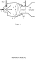
- the mixing chamber according to the invention has for this purpose Figure 1 two zones, the second zone II being regularly followed by a catalyst device K, for example in the case of ATR.
- the first zone is intended for the evaporation of the fuel and the mixing with the water vapor required for this.
- the evaporator zone I (first zone) has a feed for liquid fuel C with a nozzle. This is arranged centrally on an end face of the mixing chamber, so that the jet emerging from the single-fluid nozzle can be distributed uniformly and almost parallel to the axis in the mixing chamber.
- An advantageous nozzle is in particular a single-fluid nozzle with a spray angle of approximately 60 °.
- the generated fuel droplets C regularly have a droplet size of around 30 ⁇ m.
- the temperature in the evaporator section is regularly set around 400 ° C.
- the supply takes place via at least one pipe, with a typical diameter of approx. 3 mm to 10 mm, which is oriented in such a way that the water vapor escaping therefrom is directed directly into the fuel emerging from the nozzle.
- the nozzle is aligned tangentially so that the escaping water vapor sets the escaping fuel in a rotational movement for better mixing.
- the oxidizing agent O is then fed to the vaporized gas stream H 2 O / C mixed with water vapor. This is done by at least one feed.
- the oxidizing agent is advantageously fed in through a plurality of feeds, for example in the form of a nozzle ring.
- the feeds can advantageously also be arranged differently from the radial direction (up to approx. 15 °).
- the oxidizing agent O is supplied at a taper between zone I and zone II, as shown in FIG.
- the distance between the oxidation feed and the: one-substance nozzle for the fuel is, for example, 75 mm.
- Figure 3 represents an advantageous embodiment of the oxidizing agent supply.
- This provides for the supply of air through a pipe.
- a slot in the form of a ring is turned into the outer wall from the inside, which acts as an air distributor and is connected to the supply pipe.
- the ring-shaped air distribution is shielded from the interior by an inner sleeve. There is only a feed through several small holes that extend through the cuff into the ring-shaped air distributor of the oxidizing agent radially into the interior of the mixing chamber possible.
- the holes in the sleeve have a slight deviation of approximately 5 to 15 ° from the radial direction.
- the oxidizing agent flowing out as a result therefore also contains a tangential component which leads to greater turbulence and thus generally to effective mixing.
- the Figure 4 shows the principle of the cyclone formed evaporator zone I.
- the non-evaporated fuel droplets reach the outer edge of the chamber through the flow and are caught in the gap SP so that they do not get into the second zone.
- FIG Figure 5 Three different configurations of the cyclone evaporator part of the mixing chamber are shown in FIG Figure 5 shown.
- the lines indicate the different directions of flow within the evaporator.
Landscapes
- Chemical & Material Sciences (AREA)
- Chemical Kinetics & Catalysis (AREA)
- Organic Chemistry (AREA)
- Engineering & Computer Science (AREA)
- Combustion & Propulsion (AREA)
- General Health & Medical Sciences (AREA)
- Health & Medical Sciences (AREA)
- Inorganic Chemistry (AREA)
- Life Sciences & Earth Sciences (AREA)
- Manufacturing & Machinery (AREA)
- Sustainable Development (AREA)
- Sustainable Energy (AREA)
- Electrochemistry (AREA)
- General Chemical & Material Sciences (AREA)
- Hydrogen, Water And Hydrids (AREA)
Applications Claiming Priority (2)
| Application Number | Priority Date | Filing Date | Title |
|---|---|---|---|
| DE102004055425A DE102004055425B4 (de) | 2004-11-17 | 2004-11-17 | Mischkammer für einen Reformer sowie Verfahren zum Betreiben derselben |
| PCT/DE2005/002041 WO2006053534A1 (de) | 2004-11-17 | 2005-11-12 | Mischkammer für einen reformer sowie verfahren zum betreiben derselben |
Publications (2)
| Publication Number | Publication Date |
|---|---|
| EP1812154A1 EP1812154A1 (de) | 2007-08-01 |
| EP1812154B1 true EP1812154B1 (de) | 2020-08-19 |
Family
ID=35788324
Family Applications (1)
| Application Number | Title | Priority Date | Filing Date |
|---|---|---|---|
| EP05806947.7A Expired - Lifetime EP1812154B1 (de) | 2004-11-17 | 2005-11-12 | Mischkammer für einen reformer sowie verfahren zum betreiben derselben |
Country Status (6)
| Country | Link |
|---|---|
| US (1) | US7461618B2 (https=) |
| EP (1) | EP1812154B1 (https=) |
| JP (1) | JP4898695B2 (https=) |
| CA (1) | CA2587326C (https=) |
| DE (1) | DE102004055425B4 (https=) |
| WO (1) | WO2006053534A1 (https=) |
Families Citing this family (21)
| Publication number | Priority date | Publication date | Assignee | Title |
|---|---|---|---|---|
| US7547002B2 (en) | 2005-04-15 | 2009-06-16 | Delavan Inc | Integrated fuel injection and mixing systems for fuel reformers and methods of using the same |
| US7766251B2 (en) | 2005-12-22 | 2010-08-03 | Delavan Inc | Fuel injection and mixing systems and methods of using the same |
| DE102006016912A1 (de) * | 2006-04-11 | 2007-12-13 | Forschungszentrum Jülich GmbH | Verfahren zum Verdampfen eines flüssigen Kraftstoffs sowie eine Mischkammer zur Durchführung dieses Verfahrens |
| US8074895B2 (en) | 2006-04-12 | 2011-12-13 | Delavan Inc | Fuel injection and mixing systems having piezoelectric elements and methods of using the same |
| DE102006024038A1 (de) * | 2006-05-23 | 2007-11-29 | Forschungszentrum Jülich GmbH | Vorrichtung zur Herstellung eines Kraftstoff-Oxidationsmittel-Gemisches |
| DE102006032956B4 (de) * | 2006-07-17 | 2010-07-01 | Enerday Gmbh | Reformer und Verfahren zum Umsetzen von Brennstoff und Oxidationsmittel zu gasförmigem Reformat |
| DE102006046718A1 (de) * | 2006-10-02 | 2008-04-03 | Enerday Gmbh | Verdampfungsvorrichtung zum Aufbereiten von Brennstoff für einen Reformer und ein Brennstoffzellensystem |
| DE102007040192A1 (de) * | 2007-08-25 | 2009-02-26 | J. Eberspächer GmbH & Co. KG | Reformer und Brennstoffzellensystem |
| CN102143907A (zh) * | 2008-07-02 | 2011-08-03 | 瑞典电池公司 | 将烃类燃料转化为富氢气体的重整反应器及方法 |
| WO2010121722A1 (de) * | 2009-04-22 | 2010-10-28 | Vaillant Gmbh | Vorrichtung zum mischen von gasströmen |
| DE102009002592A1 (de) * | 2009-04-23 | 2010-10-28 | Evonik Röhm Gmbh | Dosierring |
| FR2960449B1 (fr) * | 2010-05-25 | 2012-08-03 | Inst Francais Du Petrole | Reacteur pour le reformage autotherme de gasoil |
| CA2809289A1 (en) * | 2010-09-03 | 2012-03-08 | Greg Naterer | Thermochemical reactors and processes for hydrolysis of cupric chloride |
| AT513913B1 (de) | 2013-02-04 | 2016-12-15 | Avl List Gmbh | Brennstoffzellensystem, welches mit Kohlenwasserstoffen betreibbar ist |
| AT513912B1 (de) | 2013-02-04 | 2016-08-15 | Avl List Gmbh | Energieerzeugungseinheit mit einem Hochtemperatur-Brennstoffzellenstack und einer Verdampfungseinheit |
| US20170241380A1 (en) * | 2016-02-22 | 2017-08-24 | Donald Joseph Stoddard | Liquid fuel based engine system using high velocity fuel vapor injectors |
| EP3441360B1 (en) | 2017-08-10 | 2020-07-29 | Sener Ingenieria Y Sistemas, S.A. | System for alcohol reforming and hydrogen production, units of the system and method thereof |
| KR20210097189A (ko) * | 2018-12-06 | 2021-08-06 | 라벤 에스알 엘엘씨 | 스팀/co2 개질에 의한 수소 및 ft 생성물의 제조 |
| EP3693338B1 (en) | 2019-02-07 | 2021-09-01 | Sener Ingenieria Y Sistemas, S.A. | High-pressure auto-thermal system for reforming alcohol and producing hydrogen, and method therefor |
| CN112546889B (zh) * | 2020-11-16 | 2021-07-20 | 哈尔滨工业大学 | 一种用于储释热系统热稳定输出的气体混合装置 |
| CN116272454B (zh) * | 2023-03-14 | 2026-01-30 | 上海齐耀动力技术有限公司 | 一种气体混合器及固体氧化物燃料电池发电系统 |
Citations (3)
| Publication number | Priority date | Publication date | Assignee | Title |
|---|---|---|---|---|
| CA621472A (en) * | 1961-06-06 | Farbwerke Hoechst Aktiengesellschaft Vormals Meister Lucius And Bruning | Manufacture of unsaturated hydrocarbons | |
| US4188368A (en) * | 1978-03-29 | 1980-02-12 | Nasa | Method of producing silicon |
| US20010042703A1 (en) * | 1999-08-26 | 2001-11-22 | Ito Jackson I. | Fluid atomization process |
Family Cites Families (17)
| Publication number | Priority date | Publication date | Assignee | Title |
|---|---|---|---|---|
| JPS5081989A (https=) * | 1973-08-20 | 1975-07-03 | ||
| GB2072216A (en) * | 1980-03-18 | 1981-09-30 | British Gas Corp | Treatment of hydrocarbon feedstocks |
| DE4318818C2 (de) * | 1993-06-07 | 1995-05-04 | Daimler Benz Ag | Verfahren und Vorrichtung zur Bereitstellung von konditionierter Prozessluft für luftatmende Brennstoffzellensysteme |
| JPH07315801A (ja) * | 1994-05-23 | 1995-12-05 | Ngk Insulators Ltd | 高純度水素製造システム、高純度水素の製造方法及び燃料電池システム |
| JP3196549B2 (ja) * | 1995-01-09 | 2001-08-06 | 株式会社日立製作所 | 燃料改質装置を備えた発電システム |
| DE19727841A1 (de) * | 1997-06-24 | 1999-01-07 | Fraunhofer Ges Forschung | Verfahren und Vorrichtung zur autothermen Reformierung von Kohlenwasserstoffen |
| US6472092B1 (en) * | 1998-08-12 | 2002-10-29 | Honda Giken Kogyo Kabushiki Kaisha | Fuel-reforming apparatus comprising a plate-shaped reforming catalyst |
| US6045772A (en) * | 1998-08-19 | 2000-04-04 | International Fuel Cells, Llc | Method and apparatus for injecting a liquid hydrocarbon fuel into a fuel cell power plant reformer |
| DE10141843A1 (de) * | 2000-08-30 | 2002-06-13 | Denso Corp | Wasserstoffversorgungsvorrichtung |
| JP4909488B2 (ja) * | 2000-09-20 | 2012-04-04 | 株式会社東芝 | 固体高分子型燃料電池の燃料改質装置 |
| US6875246B2 (en) * | 2001-07-20 | 2005-04-05 | General Motors Corporation | Water vapor transfer device for fuel cell reformer |
| US6872379B2 (en) * | 2001-08-15 | 2005-03-29 | Sulzer Hexis Ag | Method for the reformation of fuels, in particular heating oil |
| US6561139B2 (en) * | 2001-10-04 | 2003-05-13 | Evan Guy Enterprises, Inc. | Method and apparatus for reducing emissions of internal combustion engines |
| US6921516B2 (en) * | 2001-10-15 | 2005-07-26 | General Motors Corporation | Reactor system including auto ignition and carbon suppression foam |
| JP3807361B2 (ja) * | 2002-02-08 | 2006-08-09 | 日産自動車株式会社 | 燃料改質システムおよび燃料電池システム |
| US6660050B1 (en) * | 2002-05-23 | 2003-12-09 | Chevron U.S.A. Inc. | Method for controlling deposits in the fuel reformer of a fuel cell system |
| US20050220702A1 (en) | 2004-04-02 | 2005-10-06 | Martin Robert O | High flow rate gaseous reactant supply |
-
2004
- 2004-11-17 DE DE102004055425A patent/DE102004055425B4/de not_active Expired - Lifetime
-
2005
- 2005-11-12 US US11/791,011 patent/US7461618B2/en not_active Expired - Lifetime
- 2005-11-12 JP JP2007541666A patent/JP4898695B2/ja not_active Expired - Fee Related
- 2005-11-12 EP EP05806947.7A patent/EP1812154B1/de not_active Expired - Lifetime
- 2005-11-12 WO PCT/DE2005/002041 patent/WO2006053534A1/de not_active Ceased
- 2005-11-12 CA CA2587326A patent/CA2587326C/en not_active Expired - Lifetime
Patent Citations (3)
| Publication number | Priority date | Publication date | Assignee | Title |
|---|---|---|---|---|
| CA621472A (en) * | 1961-06-06 | Farbwerke Hoechst Aktiengesellschaft Vormals Meister Lucius And Bruning | Manufacture of unsaturated hydrocarbons | |
| US4188368A (en) * | 1978-03-29 | 1980-02-12 | Nasa | Method of producing silicon |
| US20010042703A1 (en) * | 1999-08-26 | 2001-11-22 | Ito Jackson I. | Fluid atomization process |
Also Published As
| Publication number | Publication date |
|---|---|
| DE102004055425B4 (de) | 2007-06-14 |
| JP2008520529A (ja) | 2008-06-19 |
| CA2587326C (en) | 2013-04-16 |
| DE102004055425A1 (de) | 2006-05-24 |
| US7461618B2 (en) | 2008-12-09 |
| US20080011250A1 (en) | 2008-01-17 |
| CA2587326A1 (en) | 2006-05-26 |
| JP4898695B2 (ja) | 2012-03-21 |
| EP1812154A1 (de) | 2007-08-01 |
| WO2006053534A1 (de) | 2006-05-26 |
Similar Documents
| Publication | Publication Date | Title |
|---|---|---|
| EP1812154B1 (de) | Mischkammer für einen reformer sowie verfahren zum betreiben derselben | |
| DE102010004787B4 (de) | Verfahren und Brenner zur Herstellung von Synthesegas | |
| DE102012100468B4 (de) | Brennkammer für die emissionsarme Verbrennung von mehreren vorgemischten reformierten Brennstoffen und verwandtes Verfahren | |
| EP0991587B1 (de) | Verfahren und vorrichtung zur autothermen reformierung von kohlenwasserstoffen | |
| DE69907526T2 (de) | Einsatzdruckzerstäuberdüse und Verfahren zu ihrer Verwendung | |
| DE19536837A1 (de) | Vorrichtung und Verfahren zum Einspritzen von Brennstoffen in komprimierte gasförmige Medien | |
| DE60011425T2 (de) | Sekundär reformierungsverfahren und brenner | |
| EP1497589A1 (de) | Brennkammer mit flammenloser oxidation | |
| DE2431573A1 (de) | Brenneranordnung mit verminderter emission von die luft verunreinigenden stoffen | |
| EP1327106B1 (de) | Zerstäubungsbrenner für die thermische spaltung von schwefelhaltigem reststoff | |
| WO2002023088A1 (de) | Verfahren zur regenerierung von schwefelhaltigem reststoff und zur durchführung des verfahrens geeigneter zerstäubungsbrenner | |
| EP1446610A1 (de) | Verbrennungsverfahren, insbesondere für verfahren zur erzeugung von elektrischem strom und/oder von wärme | |
| DE19951585C2 (de) | Reaktoranlage zur katalytischen Brennstoffumsetzung mit Wasser und Sauerstoff | |
| CH697265B1 (de) | Verfahren zum Erzeugen von Wasserdampf, insbesondere Reinstwasserdampf sowie Dampferzeuger. | |
| DE2655321C3 (de) | Verfahren zur Herstellung von rußarmen und schwefelfreien Verbrennungsgasen | |
| WO2007042246A2 (de) | Verfahren zur verdampfung und reformierung flüssiger brennstoffe | |
| EP1795499A2 (de) | Reformeranordnung, System mit dieser Reformeranordnung und Verfahren zum Betreiben einer Reformeranordnung | |
| DE10054921A1 (de) | Verdampfer-Rohbrennstoff-Einspritzvorrichtung | |
| DE102018128128B4 (de) | Brennerkopf, Brennersystem und Verfahren zum Betreiben eines Brennersystems | |
| DE60102930T2 (de) | Strömungsverteiler | |
| DE2309821A1 (de) | Brenner und verfahren zur herstellung eines h tief 2 und co enthaltenden produktgases | |
| EP1812337B1 (de) | Mischkammer für einen reformer sowie verfahren zum betreiben einer mischkammer | |
| EP2004318B1 (de) | Verfahren zum verdampfen eines flüssigen kraftstoffs | |
| EP0017891B1 (de) | Verfahren zur Herstellung von russfreien oder russarmen Verbrennungsgasen | |
| WO2025256895A1 (de) | Vorrichtung und verfahren zum zerstäuben und behandeln einer hochviskosen flüssigkeit |
Legal Events
| Date | Code | Title | Description |
|---|---|---|---|
| PUAI | Public reference made under article 153(3) epc to a published international application that has entered the european phase |
Free format text: ORIGINAL CODE: 0009012 |
|
| 17P | Request for examination filed |
Effective date: 20070414 |
|
| AK | Designated contracting states |
Kind code of ref document: A1 Designated state(s): AT BE BG CH CY CZ DE DK EE ES FI FR GB GR HU IE IS IT LI LT LU LV MC NL PL PT RO SE SI SK TR |
|
| DAX | Request for extension of the european patent (deleted) | ||
| 17Q | First examination report despatched |
Effective date: 20100202 |
|
| STAA | Information on the status of an ep patent application or granted ep patent |
Free format text: STATUS: EXAMINATION IS IN PROGRESS |
|
| GRAP | Despatch of communication of intention to grant a patent |
Free format text: ORIGINAL CODE: EPIDOSNIGR1 |
|
| STAA | Information on the status of an ep patent application or granted ep patent |
Free format text: STATUS: GRANT OF PATENT IS INTENDED |
|
| RIC1 | Information provided on ipc code assigned before grant |
Ipc: H01M 8/0612 20160101ALI20200121BHEP Ipc: C01B 3/38 20060101ALI20200121BHEP Ipc: B01F 3/02 20060101ALI20200121BHEP Ipc: B01J 8/02 20060101AFI20200121BHEP Ipc: B01F 5/00 20060101ALI20200121BHEP Ipc: B01J 19/00 20060101ALI20200121BHEP Ipc: B01F 5/20 20060101ALI20200121BHEP Ipc: B01J 4/00 20060101ALI20200121BHEP Ipc: B01J 19/24 20060101ALI20200121BHEP |
|
| INTG | Intention to grant announced |
Effective date: 20200212 |
|
| GRAS | Grant fee paid |
Free format text: ORIGINAL CODE: EPIDOSNIGR3 |
|
| GRAJ | Information related to disapproval of communication of intention to grant by the applicant or resumption of examination proceedings by the epo deleted |
Free format text: ORIGINAL CODE: EPIDOSDIGR1 |
|
| STAA | Information on the status of an ep patent application or granted ep patent |
Free format text: STATUS: EXAMINATION IS IN PROGRESS |
|
| INTC | Intention to grant announced (deleted) | ||
| GRAP | Despatch of communication of intention to grant a patent |
Free format text: ORIGINAL CODE: EPIDOSNIGR1 |
|
| STAA | Information on the status of an ep patent application or granted ep patent |
Free format text: STATUS: GRANT OF PATENT IS INTENDED |
|
| GRAS | Grant fee paid |
Free format text: ORIGINAL CODE: EPIDOSNIGR3 |
|
| GRAA | (expected) grant |
Free format text: ORIGINAL CODE: 0009210 |
|
| STAA | Information on the status of an ep patent application or granted ep patent |
Free format text: STATUS: THE PATENT HAS BEEN GRANTED |
|
| INTG | Intention to grant announced |
Effective date: 20200622 |
|
| REG | Reference to a national code |
Ref country code: DE Ref legal event code: R081 Ref document number: 502005016155 Country of ref document: DE Owner name: FORSCHUNGSZENTRUM JUELICH GMBH, DE Free format text: FORMER OWNER: FORSCHUNGSZENTRUM JUELICH GMBH, 52428 JUELICH, DE |
|
| AK | Designated contracting states |
Kind code of ref document: B1 Designated state(s): AT BE BG CH CY CZ DE DK EE ES FI FR GB GR HU IE IS IT LI LT LU LV MC NL PL PT RO SE SI SK TR |
|
| REG | Reference to a national code |
Ref country code: GB Ref legal event code: FG4D Free format text: NOT ENGLISH |
|
| REG | Reference to a national code |
Ref country code: CH Ref legal event code: EP |
|
| REG | Reference to a national code |
Ref country code: DE Ref legal event code: R096 Ref document number: 502005016155 Country of ref document: DE |
|
| REG | Reference to a national code |
Ref country code: AT Ref legal event code: REF Ref document number: 1303322 Country of ref document: AT Kind code of ref document: T Effective date: 20200915 |
|
| REG | Reference to a national code |
Ref country code: IE Ref legal event code: FG4D Free format text: LANGUAGE OF EP DOCUMENT: GERMAN |
|
| REG | Reference to a national code |
Ref country code: LT Ref legal event code: MG4D |
|
| REG | Reference to a national code |
Ref country code: NL Ref legal event code: MP Effective date: 20200819 |
|
| PG25 | Lapsed in a contracting state [announced via postgrant information from national office to epo] |
Ref country code: FI Free format text: LAPSE BECAUSE OF FAILURE TO SUBMIT A TRANSLATION OF THE DESCRIPTION OR TO PAY THE FEE WITHIN THE PRESCRIBED TIME-LIMIT Effective date: 20200819 Ref country code: PT Free format text: LAPSE BECAUSE OF FAILURE TO SUBMIT A TRANSLATION OF THE DESCRIPTION OR TO PAY THE FEE WITHIN THE PRESCRIBED TIME-LIMIT Effective date: 20201221 Ref country code: LT Free format text: LAPSE BECAUSE OF FAILURE TO SUBMIT A TRANSLATION OF THE DESCRIPTION OR TO PAY THE FEE WITHIN THE PRESCRIBED TIME-LIMIT Effective date: 20200819 Ref country code: BG Free format text: LAPSE BECAUSE OF FAILURE TO SUBMIT A TRANSLATION OF THE DESCRIPTION OR TO PAY THE FEE WITHIN THE PRESCRIBED TIME-LIMIT Effective date: 20201119 Ref country code: SE Free format text: LAPSE BECAUSE OF FAILURE TO SUBMIT A TRANSLATION OF THE DESCRIPTION OR TO PAY THE FEE WITHIN THE PRESCRIBED TIME-LIMIT Effective date: 20200819 Ref country code: GR Free format text: LAPSE BECAUSE OF FAILURE TO SUBMIT A TRANSLATION OF THE DESCRIPTION OR TO PAY THE FEE WITHIN THE PRESCRIBED TIME-LIMIT Effective date: 20201120 |
|
| PG25 | Lapsed in a contracting state [announced via postgrant information from national office to epo] |
Ref country code: PL Free format text: LAPSE BECAUSE OF FAILURE TO SUBMIT A TRANSLATION OF THE DESCRIPTION OR TO PAY THE FEE WITHIN THE PRESCRIBED TIME-LIMIT Effective date: 20200819 Ref country code: LV Free format text: LAPSE BECAUSE OF FAILURE TO SUBMIT A TRANSLATION OF THE DESCRIPTION OR TO PAY THE FEE WITHIN THE PRESCRIBED TIME-LIMIT Effective date: 20200819 Ref country code: NL Free format text: LAPSE BECAUSE OF FAILURE TO SUBMIT A TRANSLATION OF THE DESCRIPTION OR TO PAY THE FEE WITHIN THE PRESCRIBED TIME-LIMIT Effective date: 20200819 Ref country code: IS Free format text: LAPSE BECAUSE OF FAILURE TO SUBMIT A TRANSLATION OF THE DESCRIPTION OR TO PAY THE FEE WITHIN THE PRESCRIBED TIME-LIMIT Effective date: 20201219 |
|
| RAP4 | Party data changed (patent owner data changed or rights of a patent transferred) |
Owner name: FORSCHUNGSZENTRUM JUELICH GMBH |
|
| PG25 | Lapsed in a contracting state [announced via postgrant information from national office to epo] |
Ref country code: RO Free format text: LAPSE BECAUSE OF FAILURE TO SUBMIT A TRANSLATION OF THE DESCRIPTION OR TO PAY THE FEE WITHIN THE PRESCRIBED TIME-LIMIT Effective date: 20200819 Ref country code: DK Free format text: LAPSE BECAUSE OF FAILURE TO SUBMIT A TRANSLATION OF THE DESCRIPTION OR TO PAY THE FEE WITHIN THE PRESCRIBED TIME-LIMIT Effective date: 20200819 Ref country code: EE Free format text: LAPSE BECAUSE OF FAILURE TO SUBMIT A TRANSLATION OF THE DESCRIPTION OR TO PAY THE FEE WITHIN THE PRESCRIBED TIME-LIMIT Effective date: 20200819 Ref country code: CZ Free format text: LAPSE BECAUSE OF FAILURE TO SUBMIT A TRANSLATION OF THE DESCRIPTION OR TO PAY THE FEE WITHIN THE PRESCRIBED TIME-LIMIT Effective date: 20200819 |
|
| REG | Reference to a national code |
Ref country code: DE Ref legal event code: R097 Ref document number: 502005016155 Country of ref document: DE |
|
| PG25 | Lapsed in a contracting state [announced via postgrant information from national office to epo] |
Ref country code: ES Free format text: LAPSE BECAUSE OF FAILURE TO SUBMIT A TRANSLATION OF THE DESCRIPTION OR TO PAY THE FEE WITHIN THE PRESCRIBED TIME-LIMIT Effective date: 20200819 |
|
| PLBE | No opposition filed within time limit |
Free format text: ORIGINAL CODE: 0009261 |
|
| STAA | Information on the status of an ep patent application or granted ep patent |
Free format text: STATUS: NO OPPOSITION FILED WITHIN TIME LIMIT |
|
| PG25 | Lapsed in a contracting state [announced via postgrant information from national office to epo] |
Ref country code: MC Free format text: LAPSE BECAUSE OF FAILURE TO SUBMIT A TRANSLATION OF THE DESCRIPTION OR TO PAY THE FEE WITHIN THE PRESCRIBED TIME-LIMIT Effective date: 20200819 Ref country code: SK Free format text: LAPSE BECAUSE OF FAILURE TO SUBMIT A TRANSLATION OF THE DESCRIPTION OR TO PAY THE FEE WITHIN THE PRESCRIBED TIME-LIMIT Effective date: 20200819 |
|
| 26N | No opposition filed |
Effective date: 20210520 |
|
| PG25 | Lapsed in a contracting state [announced via postgrant information from national office to epo] |
Ref country code: LU Free format text: LAPSE BECAUSE OF NON-PAYMENT OF DUE FEES Effective date: 20201112 Ref country code: IT Free format text: LAPSE BECAUSE OF FAILURE TO SUBMIT A TRANSLATION OF THE DESCRIPTION OR TO PAY THE FEE WITHIN THE PRESCRIBED TIME-LIMIT Effective date: 20200819 |
|
| PG25 | Lapsed in a contracting state [announced via postgrant information from national office to epo] |
Ref country code: SI Free format text: LAPSE BECAUSE OF FAILURE TO SUBMIT A TRANSLATION OF THE DESCRIPTION OR TO PAY THE FEE WITHIN THE PRESCRIBED TIME-LIMIT Effective date: 20200819 |
|
| PG25 | Lapsed in a contracting state [announced via postgrant information from national office to epo] |
Ref country code: IE Free format text: LAPSE BECAUSE OF NON-PAYMENT OF DUE FEES Effective date: 20201112 |
|
| PG25 | Lapsed in a contracting state [announced via postgrant information from national office to epo] |
Ref country code: TR Free format text: LAPSE BECAUSE OF FAILURE TO SUBMIT A TRANSLATION OF THE DESCRIPTION OR TO PAY THE FEE WITHIN THE PRESCRIBED TIME-LIMIT Effective date: 20200819 Ref country code: CY Free format text: LAPSE BECAUSE OF FAILURE TO SUBMIT A TRANSLATION OF THE DESCRIPTION OR TO PAY THE FEE WITHIN THE PRESCRIBED TIME-LIMIT Effective date: 20200819 |
|
| P01 | Opt-out of the competence of the unified patent court (upc) registered |
Effective date: 20230517 |
|
| PGFP | Annual fee paid to national office [announced via postgrant information from national office to epo] |
Ref country code: GB Payment date: 20231123 Year of fee payment: 19 |
|
| PGFP | Annual fee paid to national office [announced via postgrant information from national office to epo] |
Ref country code: FR Payment date: 20231124 Year of fee payment: 19 Ref country code: CH Payment date: 20231201 Year of fee payment: 19 Ref country code: AT Payment date: 20231117 Year of fee payment: 19 |
|
| PGFP | Annual fee paid to national office [announced via postgrant information from national office to epo] |
Ref country code: BE Payment date: 20231121 Year of fee payment: 19 |
|
| PGFP | Annual fee paid to national office [announced via postgrant information from national office to epo] |
Ref country code: DE Payment date: 20241119 Year of fee payment: 20 |
|
| REG | Reference to a national code |
Ref country code: CH Ref legal event code: PL |
|
| REG | Reference to a national code |
Ref country code: AT Ref legal event code: MM01 Ref document number: 1303322 Country of ref document: AT Kind code of ref document: T Effective date: 20241112 Ref country code: CH Ref legal event code: PL |
|
| GBPC | Gb: european patent ceased through non-payment of renewal fee |
Effective date: 20241112 |
|
| PG25 | Lapsed in a contracting state [announced via postgrant information from national office to epo] |
Ref country code: CH Free format text: LAPSE BECAUSE OF NON-PAYMENT OF DUE FEES Effective date: 20241130 |
|
| PG25 | Lapsed in a contracting state [announced via postgrant information from national office to epo] |
Ref country code: AT Free format text: LAPSE BECAUSE OF NON-PAYMENT OF DUE FEES Effective date: 20241112 |
|
| REG | Reference to a national code |
Ref country code: BE Ref legal event code: MM Effective date: 20241130 |
|
| PG25 | Lapsed in a contracting state [announced via postgrant information from national office to epo] |
Ref country code: GB Free format text: LAPSE BECAUSE OF NON-PAYMENT OF DUE FEES Effective date: 20241112 Ref country code: BE Free format text: LAPSE BECAUSE OF NON-PAYMENT OF DUE FEES Effective date: 20241130 |
|
| PG25 | Lapsed in a contracting state [announced via postgrant information from national office to epo] |
Ref country code: FR Free format text: LAPSE BECAUSE OF NON-PAYMENT OF DUE FEES Effective date: 20241130 |
|
| REG | Reference to a national code |
Ref country code: DE Ref legal event code: R071 Ref document number: 502005016155 Country of ref document: DE |