EP1812154B1 - Reformer mixing chamber and method for the operation thereof - Google Patents
Reformer mixing chamber and method for the operation thereof Download PDFInfo
- Publication number
- EP1812154B1 EP1812154B1 EP05806947.7A EP05806947A EP1812154B1 EP 1812154 B1 EP1812154 B1 EP 1812154B1 EP 05806947 A EP05806947 A EP 05806947A EP 1812154 B1 EP1812154 B1 EP 1812154B1
- Authority
- EP
- European Patent Office
- Prior art keywords
- fuel
- mixing chamber
- zone
- oxidizing agent
- nozzle
- Prior art date
- Legal status (The legal status is an assumption and is not a legal conclusion. Google has not performed a legal analysis and makes no representation as to the accuracy of the status listed.)
- Active
Links
- 238000002156 mixing Methods 0.000 title claims description 58
- 238000000034 method Methods 0.000 title claims description 17
- 239000000446 fuel Substances 0.000 claims description 68
- 239000007800 oxidant agent Substances 0.000 claims description 30
- XLYOFNOQVPJJNP-UHFFFAOYSA-N water Substances O XLYOFNOQVPJJNP-UHFFFAOYSA-N 0.000 claims description 25
- 239000007788 liquid Substances 0.000 claims description 12
- 239000000126 substance Substances 0.000 claims description 8
- 239000002245 particle Substances 0.000 claims description 6
- 238000009834 vaporization Methods 0.000 claims 1
- 239000003054 catalyst Substances 0.000 description 9
- 238000001704 evaporation Methods 0.000 description 9
- 230000008020 evaporation Effects 0.000 description 9
- 239000012530 fluid Substances 0.000 description 9
- 239000007789 gas Substances 0.000 description 9
- 239000000203 mixture Substances 0.000 description 9
- 238000006243 chemical reaction Methods 0.000 description 7
- 230000015572 biosynthetic process Effects 0.000 description 6
- 238000002407 reforming Methods 0.000 description 6
- 238000009826 distribution Methods 0.000 description 5
- 229910052799 carbon Inorganic materials 0.000 description 4
- 230000003197 catalytic effect Effects 0.000 description 4
- 239000000919 ceramic Substances 0.000 description 4
- 230000000694 effects Effects 0.000 description 4
- 239000004071 soot Substances 0.000 description 4
- OKTJSMMVPCPJKN-UHFFFAOYSA-N Carbon Chemical compound [C] OKTJSMMVPCPJKN-UHFFFAOYSA-N 0.000 description 3
- OKKJLVBELUTLKV-UHFFFAOYSA-N Methanol Chemical compound OC OKKJLVBELUTLKV-UHFFFAOYSA-N 0.000 description 3
- 238000002453 autothermal reforming Methods 0.000 description 3
- 238000000265 homogenisation Methods 0.000 description 3
- 229930195733 hydrocarbon Natural products 0.000 description 3
- 150000002430 hydrocarbons Chemical class 0.000 description 3
- 230000003647 oxidation Effects 0.000 description 3
- 238000007254 oxidation reaction Methods 0.000 description 3
- 239000007858 starting material Substances 0.000 description 3
- 238000000629 steam reforming Methods 0.000 description 3
- PXHVJJICTQNCMI-UHFFFAOYSA-N Nickel Chemical compound [Ni] PXHVJJICTQNCMI-UHFFFAOYSA-N 0.000 description 2
- QVGXLLKOCUKJST-UHFFFAOYSA-N atomic oxygen Chemical compound [O] QVGXLLKOCUKJST-UHFFFAOYSA-N 0.000 description 2
- 238000000889 atomisation Methods 0.000 description 2
- 238000009835 boiling Methods 0.000 description 2
- 229910052739 hydrogen Inorganic materials 0.000 description 2
- 238000009413 insulation Methods 0.000 description 2
- VNWKTOKETHGBQD-UHFFFAOYSA-N methane Chemical compound C VNWKTOKETHGBQD-UHFFFAOYSA-N 0.000 description 2
- 229910052760 oxygen Inorganic materials 0.000 description 2
- 239000001301 oxygen Substances 0.000 description 2
- 239000004215 Carbon black (E152) Substances 0.000 description 1
- UFHFLCQGNIYNRP-UHFFFAOYSA-N Hydrogen Chemical compound [H][H] UFHFLCQGNIYNRP-UHFFFAOYSA-N 0.000 description 1
- NHTMVDHEPJAVLT-UHFFFAOYSA-N Isooctane Chemical compound CC(C)CC(C)(C)C NHTMVDHEPJAVLT-UHFFFAOYSA-N 0.000 description 1
- PIYVNGWKHNMMAU-UHFFFAOYSA-N [O].O Chemical compound [O].O PIYVNGWKHNMMAU-UHFFFAOYSA-N 0.000 description 1
- 238000000354 decomposition reaction Methods 0.000 description 1
- JVSWJIKNEAIKJW-UHFFFAOYSA-N dimethyl-hexane Natural products CCCCCC(C)C JVSWJIKNEAIKJW-UHFFFAOYSA-N 0.000 description 1
- 238000010438 heat treatment Methods 0.000 description 1
- 239000001257 hydrogen Substances 0.000 description 1
- 238000002347 injection Methods 0.000 description 1
- 239000007924 injection Substances 0.000 description 1
- 229910052500 inorganic mineral Inorganic materials 0.000 description 1
- 239000003350 kerosene Substances 0.000 description 1
- 238000004519 manufacturing process Methods 0.000 description 1
- 229910052751 metal Inorganic materials 0.000 description 1
- 239000002184 metal Substances 0.000 description 1
- 239000011707 mineral Substances 0.000 description 1
- 229910052759 nickel Inorganic materials 0.000 description 1
- 229910000510 noble metal Inorganic materials 0.000 description 1
- 231100000572 poisoning Toxicity 0.000 description 1
- 230000000607 poisoning effect Effects 0.000 description 1
- 230000002028 premature Effects 0.000 description 1
- 238000002360 preparation method Methods 0.000 description 1
- 238000000926 separation method Methods 0.000 description 1
- 239000000243 solution Substances 0.000 description 1
- 239000007921 spray Substances 0.000 description 1
- 229910001220 stainless steel Inorganic materials 0.000 description 1
- 239000010935 stainless steel Substances 0.000 description 1
- 229910052717 sulfur Inorganic materials 0.000 description 1
- 239000011593 sulfur Substances 0.000 description 1
- 230000007704 transition Effects 0.000 description 1
- 238000009827 uniform distribution Methods 0.000 description 1
Images


Classifications
-
- H—ELECTRICITY
- H01—ELECTRIC ELEMENTS
- H01M—PROCESSES OR MEANS, e.g. BATTERIES, FOR THE DIRECT CONVERSION OF CHEMICAL ENERGY INTO ELECTRICAL ENERGY
- H01M8/00—Fuel cells; Manufacture thereof
- H01M8/06—Combination of fuel cells with means for production of reactants or for treatment of residues
- H01M8/0606—Combination of fuel cells with means for production of reactants or for treatment of residues with means for production of gaseous reactants
- H01M8/0612—Combination of fuel cells with means for production of reactants or for treatment of residues with means for production of gaseous reactants from carbon-containing material
- H01M8/0618—Reforming processes, e.g. autothermal, partial oxidation or steam reforming
-
- B—PERFORMING OPERATIONS; TRANSPORTING
- B01—PHYSICAL OR CHEMICAL PROCESSES OR APPARATUS IN GENERAL
- B01J—CHEMICAL OR PHYSICAL PROCESSES, e.g. CATALYSIS OR COLLOID CHEMISTRY; THEIR RELEVANT APPARATUS
- B01J19/00—Chemical, physical or physico-chemical processes in general; Their relevant apparatus
- B01J19/0006—Controlling or regulating processes
- B01J19/002—Avoiding undesirable reactions or side-effects, e.g. avoiding explosions, or improving the yield by suppressing side-reactions
- B01J19/0026—Avoiding carbon deposits
-
- B—PERFORMING OPERATIONS; TRANSPORTING
- B01—PHYSICAL OR CHEMICAL PROCESSES OR APPARATUS IN GENERAL
- B01J—CHEMICAL OR PHYSICAL PROCESSES, e.g. CATALYSIS OR COLLOID CHEMISTRY; THEIR RELEVANT APPARATUS
- B01J19/00—Chemical, physical or physico-chemical processes in general; Their relevant apparatus
- B01J19/24—Stationary reactors without moving elements inside
- B01J19/248—Reactors comprising multiple separated flow channels
- B01J19/2485—Monolithic reactors
-
- B—PERFORMING OPERATIONS; TRANSPORTING
- B01—PHYSICAL OR CHEMICAL PROCESSES OR APPARATUS IN GENERAL
- B01J—CHEMICAL OR PHYSICAL PROCESSES, e.g. CATALYSIS OR COLLOID CHEMISTRY; THEIR RELEVANT APPARATUS
- B01J4/00—Feed or outlet devices; Feed or outlet control devices
- B01J4/001—Feed or outlet devices as such, e.g. feeding tubes
-
- C—CHEMISTRY; METALLURGY
- C01—INORGANIC CHEMISTRY
- C01B—NON-METALLIC ELEMENTS; COMPOUNDS THEREOF; METALLOIDS OR COMPOUNDS THEREOF NOT COVERED BY SUBCLASS C01C
- C01B3/00—Hydrogen; Gaseous mixtures containing hydrogen; Separation of hydrogen from mixtures containing it; Purification of hydrogen
- C01B3/02—Production of hydrogen or of gaseous mixtures containing a substantial proportion of hydrogen
- C01B3/32—Production of hydrogen or of gaseous mixtures containing a substantial proportion of hydrogen by reaction of gaseous or liquid organic compounds with gasifying agents, e.g. water, carbon dioxide, air
- C01B3/34—Production of hydrogen or of gaseous mixtures containing a substantial proportion of hydrogen by reaction of gaseous or liquid organic compounds with gasifying agents, e.g. water, carbon dioxide, air by reaction of hydrocarbons with gasifying agents
- C01B3/38—Production of hydrogen or of gaseous mixtures containing a substantial proportion of hydrogen by reaction of gaseous or liquid organic compounds with gasifying agents, e.g. water, carbon dioxide, air by reaction of hydrocarbons with gasifying agents using catalysts
- C01B3/382—Multi-step processes
-
- B—PERFORMING OPERATIONS; TRANSPORTING
- B01—PHYSICAL OR CHEMICAL PROCESSES OR APPARATUS IN GENERAL
- B01F—MIXING, e.g. DISSOLVING, EMULSIFYING OR DISPERSING
- B01F25/00—Flow mixers; Mixers for falling materials, e.g. solid particles
- B01F2025/91—Direction of flow or arrangement of feed and discharge openings
- B01F2025/913—Vortex flow, i.e. flow spiraling in a tangential direction and moving in an axial direction
-
- B—PERFORMING OPERATIONS; TRANSPORTING
- B01—PHYSICAL OR CHEMICAL PROCESSES OR APPARATUS IN GENERAL
- B01F—MIXING, e.g. DISSOLVING, EMULSIFYING OR DISPERSING
- B01F23/00—Mixing according to the phases to be mixed, e.g. dispersing or emulsifying
- B01F23/10—Mixing gases with gases
-
- B—PERFORMING OPERATIONS; TRANSPORTING
- B01—PHYSICAL OR CHEMICAL PROCESSES OR APPARATUS IN GENERAL
- B01F—MIXING, e.g. DISSOLVING, EMULSIFYING OR DISPERSING
- B01F25/00—Flow mixers; Mixers for falling materials, e.g. solid particles
- B01F25/70—Spray-mixers, e.g. for mixing intersecting sheets of material
- B01F25/72—Spray-mixers, e.g. for mixing intersecting sheets of material with nozzles
-
- B—PERFORMING OPERATIONS; TRANSPORTING
- B01—PHYSICAL OR CHEMICAL PROCESSES OR APPARATUS IN GENERAL
- B01J—CHEMICAL OR PHYSICAL PROCESSES, e.g. CATALYSIS OR COLLOID CHEMISTRY; THEIR RELEVANT APPARATUS
- B01J2219/00—Chemical, physical or physico-chemical processes in general; Their relevant apparatus
- B01J2219/00049—Controlling or regulating processes
- B01J2219/00245—Avoiding undesirable reactions or side-effects
- B01J2219/00259—Preventing runaway of the chemical reaction
- B01J2219/00265—Preventing flame propagation
-
- C—CHEMISTRY; METALLURGY
- C01—INORGANIC CHEMISTRY
- C01B—NON-METALLIC ELEMENTS; COMPOUNDS THEREOF; METALLOIDS OR COMPOUNDS THEREOF NOT COVERED BY SUBCLASS C01C
- C01B2203/00—Integrated processes for the production of hydrogen or synthesis gas
- C01B2203/02—Processes for making hydrogen or synthesis gas
- C01B2203/0205—Processes for making hydrogen or synthesis gas containing a reforming step
- C01B2203/0227—Processes for making hydrogen or synthesis gas containing a reforming step containing a catalytic reforming step
- C01B2203/0244—Processes for making hydrogen or synthesis gas containing a reforming step containing a catalytic reforming step the reforming step being an autothermal reforming step, e.g. secondary reforming processes
-
- C—CHEMISTRY; METALLURGY
- C01—INORGANIC CHEMISTRY
- C01B—NON-METALLIC ELEMENTS; COMPOUNDS THEREOF; METALLOIDS OR COMPOUNDS THEREOF NOT COVERED BY SUBCLASS C01C
- C01B2203/00—Integrated processes for the production of hydrogen or synthesis gas
- C01B2203/08—Methods of heating or cooling
- C01B2203/0805—Methods of heating the process for making hydrogen or synthesis gas
- C01B2203/0838—Methods of heating the process for making hydrogen or synthesis gas by heat exchange with exothermic reactions, other than by combustion of fuel
- C01B2203/0844—Methods of heating the process for making hydrogen or synthesis gas by heat exchange with exothermic reactions, other than by combustion of fuel the non-combustive exothermic reaction being another reforming reaction as defined in groups C01B2203/02 - C01B2203/0294
-
- C—CHEMISTRY; METALLURGY
- C01—INORGANIC CHEMISTRY
- C01B—NON-METALLIC ELEMENTS; COMPOUNDS THEREOF; METALLOIDS OR COMPOUNDS THEREOF NOT COVERED BY SUBCLASS C01C
- C01B2203/00—Integrated processes for the production of hydrogen or synthesis gas
- C01B2203/12—Feeding the process for making hydrogen or synthesis gas
- C01B2203/1205—Composition of the feed
- C01B2203/1211—Organic compounds or organic mixtures used in the process for making hydrogen or synthesis gas
- C01B2203/1235—Hydrocarbons
- C01B2203/1247—Higher hydrocarbons
-
- C—CHEMISTRY; METALLURGY
- C01—INORGANIC CHEMISTRY
- C01B—NON-METALLIC ELEMENTS; COMPOUNDS THEREOF; METALLOIDS OR COMPOUNDS THEREOF NOT COVERED BY SUBCLASS C01C
- C01B2203/00—Integrated processes for the production of hydrogen or synthesis gas
- C01B2203/12—Feeding the process for making hydrogen or synthesis gas
- C01B2203/1276—Mixing of different feed components
-
- C—CHEMISTRY; METALLURGY
- C01—INORGANIC CHEMISTRY
- C01B—NON-METALLIC ELEMENTS; COMPOUNDS THEREOF; METALLOIDS OR COMPOUNDS THEREOF NOT COVERED BY SUBCLASS C01C
- C01B2203/00—Integrated processes for the production of hydrogen or synthesis gas
- C01B2203/14—Details of the flowsheet
- C01B2203/142—At least two reforming, decomposition or partial oxidation steps in series
-
- C—CHEMISTRY; METALLURGY
- C01—INORGANIC CHEMISTRY
- C01B—NON-METALLIC ELEMENTS; COMPOUNDS THEREOF; METALLOIDS OR COMPOUNDS THEREOF NOT COVERED BY SUBCLASS C01C
- C01B2203/00—Integrated processes for the production of hydrogen or synthesis gas
- C01B2203/80—Aspect of integrated processes for the production of hydrogen or synthesis gas not covered by groups C01B2203/02 - C01B2203/1695
- C01B2203/82—Several process steps of C01B2203/02 - C01B2203/08 integrated into a single apparatus
-
- Y—GENERAL TAGGING OF NEW TECHNOLOGICAL DEVELOPMENTS; GENERAL TAGGING OF CROSS-SECTIONAL TECHNOLOGIES SPANNING OVER SEVERAL SECTIONS OF THE IPC; TECHNICAL SUBJECTS COVERED BY FORMER USPC CROSS-REFERENCE ART COLLECTIONS [XRACs] AND DIGESTS
- Y02—TECHNOLOGIES OR APPLICATIONS FOR MITIGATION OR ADAPTATION AGAINST CLIMATE CHANGE
- Y02E—REDUCTION OF GREENHOUSE GAS [GHG] EMISSIONS, RELATED TO ENERGY GENERATION, TRANSMISSION OR DISTRIBUTION
- Y02E60/00—Enabling technologies; Technologies with a potential or indirect contribution to GHG emissions mitigation
- Y02E60/30—Hydrogen technology
- Y02E60/50—Fuel cells
Definitions
- the invention relates to an effective mixing chamber for a reformer, in particular for a reformer for producing middle distillates, and to a method for operating this mixing chamber.
- the oxygen is usually provided by means of air.
- the heat that is necessary for steam reforming is made available through the partial oxidation of the hydrocarbon.
- the process can thus be run in an autothermal operating mode. In principle a higher degree of efficiency is possible, since system-related enthalpy losses are only possible through the warm product gas flow.
- Autothermal reforming appears to be very promising, especially for the use of fuel cell systems to drive vehicles with gasoline or diesel as fuel. This can be explained by the high reaction temperature (approx. 800 ° C) and good reaction kinetics.
- a poor quality of the educt mixture regularly has a negative effect on the conversion of the fuel.
- the fuel is usually injected directly through a single-fluid or multi-fluid nozzle.
- a single-fluid nozzle the fuel is atomized at high pressure.
- suitable single-fluid nozzles are the continuous swirl pressure atomizing nozzle, as is customary in smaller boilers for heating oil, or the high-pressure injector, as is used in today's gasoline and diesel engines.
- the Venturi tube which is used to suck in and atomize a liquid, should also be mentioned.
- the fuel is usually atomized together with a gas flow. Such nozzles produce very fine droplets with a diameter of approx. 10 to 30 ⁇ m.
- a three-substance nozzle is also known in which, in addition to the liquid fuel and air, superheated water vapor is also passed through the nozzle.
- Such a multi-substance nozzle for atomizing the liquid fuel is off U.S. 6,045,772 A known.
- the required heat can also be achieved by partially burning the fuel, or the mixing chamber can be heated by an external heater.
- the object of the invention is to provide a particularly effective mixing chamber for a reformer, which allows a particularly uniform distribution of the starting materials and a homogenization of the flow distribution, and can thus be operated particularly effectively. It is also the object of the invention to provide a mixing chamber which largely avoids undesirable soot formation and deposits on the reforming catalyst and converts the fuel as completely as possible in the subsequent reformer.
- the mixing chamber should also be able to be used in particular for low-sulfur diesel and kerosene.
- the invention describes a mixing chamber in which a fuel and an oxidizing agent are mixed, this mixture then being provided for supply to a reforming catalytic converter.
- a mixing chamber could for example be part of an autothermal reformer (ATR).
- ATR autothermal reformer
- the mixing chamber according to the invention for a reformer consists of metal or ceramic.
- Ceramic is advantageous because it usually requires less thermal insulation and, above all, when stainless steel is used, the nickel that is present can cause some undesirable reactions as a catalyst. Such disadvantages can be avoided by using ceramics.
- the mixing chamber according to the invention according to claim 9 has a feed line with a: one-substance nozzle for a liquid fuel, a feed line for water vapor and a feed line for an oxidizing agent, in particular for air.
- the mixing chamber can be divided into two zones, in which the fuel is vaporized and uniformly distributed in the first zone, while the fuel vaporised uniformly is mixed intensively and uniformly with an oxidizing agent in the second zone.
- the feed line and the: one-substance nozzle for the fuel and the feed for the water vapor are arranged within the first zone in such a way that the nozzle for the fuel is arranged adjacent to the feed line for the water vapor, so that the fuel injected and atomized into the interior of the mixing chamber is immediately evaporated in hot water vapor.
- At least one feed for the oxidizing agent, preferably for air, is arranged at the boundary to the second zone of the mixing chamber.
- the feed can advantageously have several outlets, for example in the form of a nozzle ring. It has been found that a pronounced vortex structure is necessary to achieve rapid mixing and good mixture quality. So that the gases are mixed at the highest possible speeds, a narrowing of the mixing chamber is provided in the area of the feed.
- the oxidizing agent is advantageously supplied radially from several narrow openings. However, this is explicitly not the principle of a Venturi tube.
- the water is thermally pretreated; H. evaporated and overheated.
- the water vapor is introduced into the first zone of the mixing chamber, in particular at a temperature in the range from 350 ° C. to 500 ° C.
- the water vapor atmosphere in the first zone advantageously prevents carbon formation.
- the temperature of the first zone of the mixing chamber is at least 50 K higher than the boiling temperature of the fuel.
- the mixing chamber is in the form of a cyclone which is tapered in the direction of the nozzle for the fuel and in the direction of the second zone.
- This tapering has the advantageous effect that outside the actual mixing and evaporation zone, disturbing eddies can regularly be significantly reduced or completely prevented.
- the taper around the nozzle for the fuel has been found to be very effective.
- the Reduction of the diameter of the first zone is a maximum of 85% of the diameter in the evaporator zone.
- the first zones of the mixing chamber are in each case in the form of cyclone separators.
- the fuel used has a certain amount of low-boiling hydrocarbons and minerals. With these fuels, complete evaporation is physically not possible under the given framework conditions. So that the non-evaporated fuel residues do not reach the catalyst surface of the monolith, i.e. the ceramic carrier with honeycomb structure coated with noble metals, where they would lead to poisoning and thus to a reduction in activity, it is important to remove them from the gas flow. It would be desirable to remove these particles before the oxidizing agent is fed into the second zone.
- the dynamic principle is used, by which one can separate non-evaporated liquid from a gas flow with the help of centrifugal force, for example in a cyclone separator.
- the first zone is a classic cyclone to which the fuel and the water vapor are both supplied tangentially.
- the evaporator would have to be designed to be relatively large, especially if the thermal insulation is also taken into account.
- the atomizer nozzle for the fuel is on the front side of the mixing chamber in the axis of the mixing chamber and only the feed for the Water vapor arranged tangentially.
- the opening which represents the exit from the evaporator, or the transition between the first and second zone, is structurally positioned in the direction of the atomizer nozzle so that an annular gap is formed between the wall of the evaporator and the second zone.
- the non-evaporated particles are regularly directed into this gap by centrifugal force during operation, while the gas phase flows centrally from the evaporator into the second zone.
- the hardly volatile particles and deposits collected in the gap can therefore not get into the catalytic converter and also do not impair the rest of the flow.
- the single-fluid nozzle for the fuel feed points in the direction of the second zone of the mixing chamber.
- There an oxidizing agent is added to the completely vaporized and evenly distributed fuel.
- the oxidizing agent is advantageously also fed in in the cold state.
- the supply line for the oxidizing agent regularly has several openings.
- a nozzle ring in particular has proven to be very effective.
- the oxidizing agent is fed in shortly before it enters the reforming catalytic converter. This can reduce the period of time before entry into the reforming catalytic converter in which the gaseous fuel is exposed to the oxidizing agent. In this way, the risk of premature burning or ignition of the fuel-air mixture is regularly reduced or can be prevented entirely.
- the flow guidance in the mixing chamber is such that there is no recirculation of the fuel mixed with the oxidizing agent back from the second zone can come into the first zone. This ensures in the first zone, due to the lack of oxygen, that there is no ignition, and also that soot formation is prevented.
- the starting materials of a reformer should by means of exact metering, mixture formation, possibly evaporation and homogeneous flow distribution in the direction of the catalyst Will be provided. This is realized in the mixing chamber according to the invention. As an example, for an ATR with an output of 3 kW el, 3.6 kg / h of air, 1.73 kg / h of water and 800 g / h of fuel are introduced into the mixing chamber.
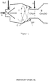
- the mixing chamber according to the invention has for this purpose Figure 1 two zones, the second zone II being regularly followed by a catalyst device K, for example in the case of ATR.
- the first zone is intended for the evaporation of the fuel and the mixing with the water vapor required for this.
- the evaporator zone I (first zone) has a feed for liquid fuel C with a nozzle. This is arranged centrally on an end face of the mixing chamber, so that the jet emerging from the single-fluid nozzle can be distributed uniformly and almost parallel to the axis in the mixing chamber.
- An advantageous nozzle is in particular a single-fluid nozzle with a spray angle of approximately 60 °.
- the generated fuel droplets C regularly have a droplet size of around 30 ⁇ m.
- the temperature in the evaporator section is regularly set around 400 ° C.
- the supply takes place via at least one pipe, with a typical diameter of approx. 3 mm to 10 mm, which is oriented in such a way that the water vapor escaping therefrom is directed directly into the fuel emerging from the nozzle.
- the nozzle is aligned tangentially so that the escaping water vapor sets the escaping fuel in a rotational movement for better mixing.
- the oxidizing agent O is then fed to the vaporized gas stream H 2 O / C mixed with water vapor. This is done by at least one feed.
- the oxidizing agent is advantageously fed in through a plurality of feeds, for example in the form of a nozzle ring.
- the feeds can advantageously also be arranged differently from the radial direction (up to approx. 15 °).
- the oxidizing agent O is supplied at a taper between zone I and zone II, as shown in FIG.
- the distance between the oxidation feed and the: one-substance nozzle for the fuel is, for example, 75 mm.
- Figure 3 represents an advantageous embodiment of the oxidizing agent supply.
- This provides for the supply of air through a pipe.
- a slot in the form of a ring is turned into the outer wall from the inside, which acts as an air distributor and is connected to the supply pipe.
- the ring-shaped air distribution is shielded from the interior by an inner sleeve. There is only a feed through several small holes that extend through the cuff into the ring-shaped air distributor of the oxidizing agent radially into the interior of the mixing chamber possible.
- the holes in the sleeve have a slight deviation of approximately 5 to 15 ° from the radial direction.
- the oxidizing agent flowing out as a result therefore also contains a tangential component which leads to greater turbulence and thus generally to effective mixing.
- the Figure 4 shows the principle of the cyclone formed evaporator zone I.
- the non-evaporated fuel droplets reach the outer edge of the chamber through the flow and are caught in the gap SP so that they do not get into the second zone.
- FIG Figure 5 Three different configurations of the cyclone evaporator part of the mixing chamber are shown in FIG Figure 5 shown.
- the lines indicate the different directions of flow within the evaporator.
Landscapes
- Chemical & Material Sciences (AREA)
- Chemical Kinetics & Catalysis (AREA)
- Organic Chemistry (AREA)
- Engineering & Computer Science (AREA)
- Sustainable Development (AREA)
- Sustainable Energy (AREA)
- Manufacturing & Machinery (AREA)
- Electrochemistry (AREA)
- General Chemical & Material Sciences (AREA)
- Life Sciences & Earth Sciences (AREA)
- Health & Medical Sciences (AREA)
- General Health & Medical Sciences (AREA)
- Combustion & Propulsion (AREA)
- Inorganic Chemistry (AREA)
- Hydrogen, Water And Hydrids (AREA)
Description
Die Erfindung betrifft eine effektive Mischkammer für einen Reformer, insbesondere für einen Reformer zur Erzeugung von Mitteldestillaten, sowie ein Verfahren zum Betreiben dieser Mischkammer.The invention relates to an effective mixing chamber for a reformer, in particular for a reformer for producing middle distillates, and to a method for operating this mixing chamber.
Neben der klassischen Dampfreformierung zur Wasserstoffproduktion stellt die autotherme Reformierung eine vielversprechende Alternative dar. Dabei reagiert ein Sauerstoff-Wasser-Gemisch im Reaktor ohne externe Wärmequelle mit Kohlenwasserstoff CnHm entsprechend folgender Gleichungen:
Für Methan CH4 (n = 1, m = 4) stellen sich die Reaktionsgleichungen wie folgt dar:
Der Sauerstoff wird in der Regel mittels Luft bereitgestellt. Die Wärme, die für die Dampfreformierung notwendig ist, wird durch die partielle Oxidation des Kohlenwasserstoffs zur Verfügung gestellt. Der Prozess kann somit in einem autothermen Betriebsmodus gefahren werden. Prinzipiell ist ein höherer Wirkungsgrad möglich, da systembezogene Enthalpieverluste nur durch den warmen Produktgasstrom möglich sind. Besonders für den Gebrauch von Brennstoffzellensystemen als Fahrzeugantrieb mit Benzin oder Diesel als Kraftstoff scheint die autotherme Reformierung sehr viel versprechend. Dies ist durch die hohe Reaktionstemperatur (ca. 800 °C) und eine gute Reaktionskinetik zu erklären.The oxygen is usually provided by means of air. The heat that is necessary for steam reforming is made available through the partial oxidation of the hydrocarbon. The process can thus be run in an autothermal operating mode. In principle a higher degree of efficiency is possible, since system-related enthalpy losses are only possible through the warm product gas flow. Autothermal reforming appears to be very promising, especially for the use of fuel cell systems to drive vehicles with gasoline or diesel as fuel. This can be explained by the high reaction temperature (approx. 800 ° C) and good reaction kinetics.
Neben der Entwicklung von geeigneten Katalysatoren für die autotherme Reformierung von Mitteldestillaten hängt die Einsatzfähigkeit eines Reformers wesentlich davon ab, ob optimierte Betriebsbedingungen eingestellt werden können.
Die Reformierung von flüssigen Kraftstoffen stellt hohe Ansprüche an die Vorbereitung der Edukte, bevor sie in die Reaktionszone des Reaktors, d. h. des Reformers eintreten.In addition to the development of suitable catalysts for the autothermal reforming of middle distillates, the usability of a reformer essentially depends on whether optimized operating conditions can be set.
The reforming of liquid fuels places high demands on the preparation of the starting materials before they enter the reaction zone of the reactor, ie the reformer.
Eine schlechte Qualität des Eduktgemisches hat regelmäßig eine negative Wirkung auf den Umsatz des Kraftstoffs. Um die Rußbildung und so genannte "Hot Spots" in der Reaktionszone zu vermeiden, ist es insbesondere wichtig, dass die O2/C- und H2O/C-Verhältnisse im Gemisch möglichst konstant bleiben und nicht schwanken.A poor quality of the educt mixture regularly has a negative effect on the conversion of the fuel. In order to avoid the formation of soot and so-called "hot spots" in the reaction zone, it is particularly important that the O 2 / C and H 2 O / C ratios in the mixture remain as constant as possible and do not fluctuate.
Die Mischkammer eines Reformers hat daher die folgenden Funktionen:
- Zuführung des Kraftstoffs
- Zerstäubung und Verdampfung des Kraftstoffs
- Gemischbildung (Homogenisierung der Kraftstoffkonzentration im Luft-Dampf-Strom)
- Homogenisierung der Durchflussverteilung (Fließgeschwindigkeitsprofil)
- Feeding the fuel
- Atomization and evaporation of the fuel
- Mixture formation (homogenization of the fuel concentration in the air-vapor flow)
- Homogenization of the flow distribution (flow velocity profile)
Aus dem Stand der Technik sind zwei prinzipielle Möglichkeiten der Kraftstoffzuführung bekannt, die gasförmige Zuführung über einen externen Verdampfer und die interne Einspritzung und Zerstäubung des flüssigen Kraftstoffs.
Eine separate Verdampfung des Kraftstoffs wird dabei häufig bei reinen Stoffen, wie beispielsweise Methanol oder iso-Oktan angewandt. Bei komplexeren Kraftstoffmischungen wie Benzin oder Diesel steigt die Gefahr, dass sich auf der heißen Oberfläche des Verdampfers kohlenstoffhaltige Ablagerungen bilden und abscheiden. Nachteilig wird bei diesen Verfahren eine zusätzliche externe Wärmequelle benötigt und die Steuerung gestaltet sich aufgrund der Wärmekapazität des Verdampfers regelmäßig schwierig.There are two basic possibilities from the prior art the fuel supply is known, the gaseous supply via an external evaporator and the internal injection and atomization of the liquid fuel.
Separate evaporation of the fuel is often used for pure substances such as methanol or iso-octane. With more complex fuel mixtures such as gasoline or diesel, the risk increases that carbon-containing deposits will form and deposit on the hot surface of the evaporator. The disadvantage of these methods is that an additional external heat source is required and control is regularly difficult due to the heat capacity of the evaporator.
Eine direkte Einspritzung des Kraftstoffs erfolgt üblicherweise durch eine Einstoff- oder eine Mehrstoffdüse. Bei einer Einstoffdüse wird der Kraftstoff mit hohem Druck zerstäubt. Beispiele für geeignete Einstoffdüsen sind die kontinuierliche Dralldruckzerstäubungsdüse, wie sie in kleineren Heizkesseln für Heizöl üblich ist, oder der Hochdruckinjektor, wie sie in heutigen Benzin- und Dieselmotoren eingesetzt werden. Auch zu nennen ist das Venturirohr, welches zum Ansaugen und Zerstäuben einer Flüssigkeit dient.
Bei Verwendung einer Mehrstoffdüse wird der Kraftstoff in der Regel zusammen mit einem Gasstrom zerstäubt. Solche Düsen erzeugen sehr feine Tropfen mit einem Durchmesser von ca. 10 bis 30 µm. Es ist auch schon eine Dreistoffdüse bekannt, bei der neben dem flüssigen Kraftstoff und Luft zusätzlich überhitzter Wasserdampf durch die Düse geleitet wird.The fuel is usually injected directly through a single-fluid or multi-fluid nozzle. With a single-fluid nozzle, the fuel is atomized at high pressure. Examples of suitable single-fluid nozzles are the continuous swirl pressure atomizing nozzle, as is customary in smaller boilers for heating oil, or the high-pressure injector, as is used in today's gasoline and diesel engines. The Venturi tube, which is used to suck in and atomize a liquid, should also be mentioned.
When using a multi-fuel nozzle, the fuel is usually atomized together with a gas flow. Such nozzles produce very fine droplets with a diameter of approx. 10 to 30 µm. A three-substance nozzle is also known in which, in addition to the liquid fuel and air, superheated water vapor is also passed through the nozzle.
Eine derartige Mehrstoffdüse zur Zerstäubung des flüssigen Kraftstoffs ist aus
Zur vollständigen Verdampfung des zerstäubten Kraftstoffs wird viel Wärme benötigt, die beispielsweise durch einen heißen, gasförmigen Eduktstrom aus Luft und/oder Wasserdampf zugeführt wird. Dabei ist jedoch die Tatsache zu beachten, dass bei bestimmten Bedingungen, die für die Verdampfung benötigte Temperatur des Gasstromes die Zündtemperatur des Kraftstoffs überschritten werden kann.A lot of heat is required for complete evaporation of the atomized fuel, which is supplied, for example, by a hot, gaseous feed stream of air and / or water vapor. However, the fact must be taken into account that under certain conditions, the temperature of the gas flow required for evaporation, the ignition temperature of the fuel can be exceeded.
Alternativ kann die benötigte Wärme auch durch eine teilweise Verbrennung des Kraftstoffs erzielt, oder die Mischkammer durch eine externe Heizung erwärmt werden.Alternatively, the required heat can also be achieved by partially burning the fuel, or the mixing chamber can be heated by an external heater.
Bei allen vorgenannten Verfahren können jedoch durch die Zersetzung des Kraftstoffs nachteilig kohlenstoffhaltige Ablagerungen auftreten, die sich insbesondere auf dem Reformierungskatalysator in Form von Ruß abscheiden und so zu einer zunehmend verringerten Aktivität desselben führen.In all of the aforementioned processes, however, the decomposition of the fuel can disadvantageously result in carbon-containing deposits, which are deposited in particular on the reforming catalyst in the form of soot and thus lead to an increasingly reduced activity of the same.
Die Aufgabe der Erfindung ist es, eine besonders effektive Mischkammer für einen Reformer bereit zu stellen, der eine besonders gleichmäßige Verteilung der Edukte und eine Homogenisierung der Durchflussverteilung ermöglicht, und somit besonders effektiv zu betreiben ist. Ferner ist es die Aufgabe der Erfindung, eine Mischkammer bereit zu stellen, die eine unerwünschte Rußbildung und Ablagerung auf dem Reformierungskatalysator weitgehend vermeidet und den Kraftstoff im sich anschließenden Reformer möglichst vollständig umsetzt. Dabei sollte die Mischkammer insbesondere auch für schwefelarmen Diesel und Kerosin einsetzbar sein.The object of the invention is to provide a particularly effective mixing chamber for a reformer, which allows a particularly uniform distribution of the starting materials and a homogenization of the flow distribution, and can thus be operated particularly effectively. It is also the object of the invention to provide a mixing chamber which largely avoids undesirable soot formation and deposits on the reforming catalyst and converts the fuel as completely as possible in the subsequent reformer. The mixing chamber should also be able to be used in particular for low-sulfur diesel and kerosene.
Die Aufgaben der Erfindung werden gelöst durch ein Verfahren zum Betreiben einer Mischkammer mit der Gesamtheit an Merkmalen gemäß Hauptanspruch, sowie durch eine Mischkammer für einen Reformer gemäß Nebenanspruch. Vorteilhafte Ausführungsformen des Verfahrens und der Vorrichtung finden sich in den jeweils darauf rückbezogenen Ansprüchen wieder.The objects of the invention are achieved by a method for operating a mixing chamber with the entirety of the features according to the main claim, as well as by a mixing chamber for a reformer according to the secondary claim. Advantageous embodiments of the method and the device can be found in the claims that refer back to them.
Die Erfindung beschreibt eine Mischkammer, in der ein Kraftstoff und ein Oxidationsmittel gemischt werden, wobei dieses Gemisch anschließend zur Zuführung zu einem Reformierungskatalysator vorgesehen ist. Eine solche Mischkammer könnte beispielsweise Teil eines autothermen Reformers (ATR) sein. Die erfindungsgemäße Mischkammer für einen Reformer besteht aus Metall oder Keramik.The invention describes a mixing chamber in which a fuel and an oxidizing agent are mixed, this mixture then being provided for supply to a reforming catalytic converter. Such a mixing chamber could for example be part of an autothermal reformer (ATR). The mixing chamber according to the invention for a reformer consists of metal or ceramic.
Keramik ist vorteilhaft, da in der Regel eine geringere thermische Isolierung benötigt und vor allem kann aber bei der Verwendung von Edelstahl das anwesende Nickel einige unerwünschte Reaktionen als Katalysator verursachen. Solche Nachteile können bei Verwendung von Keramik verhindert werden.Ceramic is advantageous because it usually requires less thermal insulation and, above all, when stainless steel is used, the nickel that is present can cause some undesirable reactions as a catalyst. Such disadvantages can be avoided by using ceramics.
Die erfindungsgemäße Mischkammer gemäss Anspruch 9 weist eine Zuführungsleitung mit einer : Einstoffdüse für einen flüssigen Kraftstoff, eine Zuführungsleitung für Wasserdampf sowie eine Zuführungsleitung für ein Oxidationsmittel, insbesondere für Luft auf. Die Mischkammer kann in zwei Zonen unterteilt werden, bei der in der ersten Zone die Verdampfung des Kraftstoffs und die gleichmäßige Verteilung stattfindet, während in der zweiten Zone, der gleichmäßig verdampfte Kraftstoff intensiv und gleichförmig mit einem Oxidationsmittel vermischt wird.The mixing chamber according to the invention according to claim 9 has a feed line with a: one-substance nozzle for a liquid fuel, a feed line for water vapor and a feed line for an oxidizing agent, in particular for air. The mixing chamber can be divided into two zones, in which the fuel is vaporized and uniformly distributed in the first zone, while the fuel vaporised uniformly is mixed intensively and uniformly with an oxidizing agent in the second zone.
Die Zuleitung und die : Einstoffdüse für den Kraftstoff und die Zuführung für den Wasserdampf sind innerhalb der ersten Zone derart angeordnet, dass die Düse für den Kraftstoff benachbart zu der Zuführung des Wasserdampfes angeordnet ist, so dass der ins Innere der Mischkammer eingespritzte und zerstäubte Kraftstoff sofort im heißen Wasserdampf verdampft.
Abstromig zu dem eingeleiteten Kraftstoff und dem Wasserdampf ist an der Grenze zur zweiten Zone der Mischkammer wenigstens eine Zuführung für das Oxidationsmittel, bevorzugt für Luft, angeordnet. Die Zuführung kann vorteilhaft mehrere Auslässe, beispielsweise in Form eines Düsenkranzes aufweisen. Es hat sich herausgestellt, dass zur Erreichung einer schnellen Mischung und einer gute Gemischqualität eine ausgeprägte Wirbelstruktur notwendig ist. Damit die Gase bei möglichst hohen Geschwindigkeiten gemischt werden, ist eine Verengung der Mischkammer in dem Bereich der Zuführung vorgesehen. Das Oxidationsmittel wird vorteilhaft radial aus mehreren engen Öffnungen zugeführt. Es handelt sich dabei aber explizit nicht um das Prinzip eines Venturi-Rohrs.The feed line and the: one-substance nozzle for the fuel and the feed for the water vapor are arranged within the first zone in such a way that the nozzle for the fuel is arranged adjacent to the feed line for the water vapor, so that the fuel injected and atomized into the interior of the mixing chamber is immediately evaporated in hot water vapor.
Downstream of the injected fuel and water vapor At least one feed for the oxidizing agent, preferably for air, is arranged at the boundary to the second zone of the mixing chamber. The feed can advantageously have several outlets, for example in the form of a nozzle ring. It has been found that a pronounced vortex structure is necessary to achieve rapid mixing and good mixture quality. So that the gases are mixed at the highest possible speeds, a narrowing of the mixing chamber is provided in the area of the feed. The oxidizing agent is advantageously supplied radially from several narrow openings. However, this is explicitly not the principle of a Venturi tube.
Bei dem erfindungsgemäßen Verfahren zum Betreiben der Mischkammer wird lediglich das Wasser thermisch vorbehandelt, d. h. verdampft und überhitzt. Der Wasserdampf wird insbesondere mit einer Temperatur im Bereich von 350 °C bis 500 °C in die erste Zone der Mischkammer eingeleitet. Der mit Hilfe einer Einstoffdüse in die erste Zone eingespritzte Kraftstoff, der kalt, das bedeutet beispielsweise mit Raumtemperatur zugeführt wird, verdampft augenblicklich. Die Wasserdampfatmosphäre in der ersten Zone verhindert vorteilhaft eine Kohlenstoffbildung. Die Temperatur der ersten Zone der Mischkammer weist während des Betriebs eine wenigstens um 50 K höhere Temperatur als die Siedetemperatur des Kraftstoffs auf.In the method according to the invention for operating the mixing chamber, only the water is thermally pretreated; H. evaporated and overheated. The water vapor is introduced into the first zone of the mixing chamber, in particular at a temperature in the range from 350 ° C. to 500 ° C. The fuel injected into the first zone with the aid of a single-fluid nozzle, which is supplied cold, that is to say, for example, at room temperature, evaporates immediately. The water vapor atmosphere in the first zone advantageously prevents carbon formation. During operation, the temperature of the first zone of the mixing chamber is at least 50 K higher than the boiling temperature of the fuel.
Erfindungsgemäß liegt die Mischkammer in Form eines Zyklons vor, der in Richtung auf die Düse für den Kraftstoff und in Richtung auf die zweite Zone eine Verjüngung aufweist. Diese Verjüngung bewirkt vorteilhaft, dass sich au-ßerhalb der eigentlichen Vermischungs- und Verdampfungszone störende Wirbel regelmäßig deutlich verringern bzw. ganz verhindern lassen. Die Verjüngung rund um die Düse für den Kraftstoff hat sich als sehr effektiv herausgestellt. Die Reduzierung des Durchmessers der ersten Zone beträgt maximal 85 % des Durchmessers in der Verdampferzone.According to the invention, the mixing chamber is in the form of a cyclone which is tapered in the direction of the nozzle for the fuel and in the direction of the second zone. This tapering has the advantageous effect that outside the actual mixing and evaporation zone, disturbing eddies can regularly be significantly reduced or completely prevented. The taper around the nozzle for the fuel has been found to be very effective. The Reduction of the diameter of the first zone is a maximum of 85% of the diameter in the evaporator zone.
In vorteilhaften Ausführungsformen liegen jeweils die ersten Zonen der Mischkammer als Zyklonabscheider vor. Dies ist insbesondere dann von Vorteil, wenn der eingesetzte Kraftstoff eine gewisse Menge an schwer siedenden Kohlenwasserstoffen und Mineralien aufweist. Bei diesen Kraftstoffen ist eine vollständige Verdampfung unter den gegebenen Rahmenbedingungen physikalisch nicht möglich. Damit die nicht verdampften Kraftstoffrückstände nicht bis zur Katalysatoroberfläche des Monoliths, das heißt der mit Edelmetallen beschichteten keramischen Träger mit Wabenstruktur, gelangen, wo sie zu Vergiftungen und damit zu einer Senkung der Aktivität führen würden, ist es wichtig, diese aus dem Gasstrom zu entfernen. Wünschenswert wäre die Entfernung diese Partikel noch vor der Zuführung des Oxidationsmittels in der zweiten Zone.In advantageous embodiments, the first zones of the mixing chamber are in each case in the form of cyclone separators. This is particularly advantageous when the fuel used has a certain amount of low-boiling hydrocarbons and minerals. With these fuels, complete evaporation is physically not possible under the given framework conditions. So that the non-evaporated fuel residues do not reach the catalyst surface of the monolith, i.e. the ceramic carrier with honeycomb structure coated with noble metals, where they would lead to poisoning and thus to a reduction in activity, it is important to remove them from the gas flow. It would be desirable to remove these particles before the oxidizing agent is fed into the second zone.
Zu diesem Zweck wird das dynamische Prinzip ausgenutzt, durch welches man mit Hilfe der Zentrifugalkraft, beispielsweise in einem Zyklonabscheider, nicht verdampfte Flüssigkeit aus einem Gasstrom abtrennen kann. Allerdings hat es sich herausgestellt, dass es nicht wirksam ist, die erste Zone als klassischen Zyklon auszulegen, dem der Kraftstoff und der Wasserdampf beide tangential zugeführt werden. Vor der Zerstäuberdüse sollten mindestens 3 bis 4 cm freien Raum verbleiben, um zunächst die Verdampfung zu ermöglichen, bevor die Kraftstofftröpfchen die Wand der Mischkammer, bzw. des Zyklons erreichen. Dafür müsste aber der Verdampfer relativ groß ausgelegt werden, insbesondere wenn auch noch die thermische Isolierung in Betracht gezogen wird.For this purpose, the dynamic principle is used, by which one can separate non-evaporated liquid from a gas flow with the help of centrifugal force, for example in a cyclone separator. However, it has been found that it is not effective to design the first zone as a classic cyclone to which the fuel and the water vapor are both supplied tangentially. There should be at least 3 to 4 cm of free space in front of the atomizer nozzle in order to allow evaporation before the fuel droplets reach the wall of the mixing chamber or the cyclone. For this, however, the evaporator would have to be designed to be relatively large, especially if the thermal insulation is also taken into account.
Erfindungsgemäß ist bei der Mischkammer daher die Zerstäuberdüse für den Kraftstoff an der Stirnseite der Mischkammer in der Achse der Mischkammer und nur die Zuführung für den Wasserdampf tangential angeordnet. Zudem wird die Öffnung, die den Austritt aus dem Verdampfer, bzw. den Übergang zwischen erster und zweiter Zone darstellt, konstruktiv so in Richtung Zerstäuberdüse gelegt, dass sich zwischen der Wand des Verdampfers und der zweiten Zone ein ringförmiger Spalt ausbildet. Die nicht verdampften Partikel werden während des Betriebs regelmäßig durch die Zentrifugalkraft in diesen Spalt gelenkt, während die Gasphase zentral aus dem Verdampfer in die zweite Zone strömt. Die in dem Spalt gesammelten, schwer flüchtigen Partikel und Ablagerungen können somit nicht in den Katalysator gelangen und führen auch nicht zu einer Beeinträchtigung der übrigen Strömungsführung.According to the invention, therefore, in the mixing chamber, the atomizer nozzle for the fuel is on the front side of the mixing chamber in the axis of the mixing chamber and only the feed for the Water vapor arranged tangentially. In addition, the opening, which represents the exit from the evaporator, or the transition between the first and second zone, is structurally positioned in the direction of the atomizer nozzle so that an annular gap is formed between the wall of the evaporator and the second zone. The non-evaporated particles are regularly directed into this gap by centrifugal force during operation, while the gas phase flows centrally from the evaporator into the second zone. The hardly volatile particles and deposits collected in the gap can therefore not get into the catalytic converter and also do not impair the rest of the flow.
Die Einstoffdüse für die Kraftstoffeinspeisung (Zerstäuberdüse) weist in Richtung der zweiten Zone der Mischkammer. Dort wird dem vollständig verdampften und gleichmäßig verteilten Kraftstoff ein Oxidationsmittel zugeführt. Das Oxidationsmittel wird vorteilhaft ebenfalls in kaltem Zustand eingespeist. Für eine schnelle und gleichmäßige Verteilung des Oxidationsmittels weist die Zufuhrleitung für das Oxidationsmittel regelmäßig mehrere Öffnungen auf. Insbesondere ein Düsenkranz hat sich als sehr effektiv herausgestellt.The single-fluid nozzle for the fuel feed (atomizer nozzle) points in the direction of the second zone of the mixing chamber. There an oxidizing agent is added to the completely vaporized and evenly distributed fuel. The oxidizing agent is advantageously also fed in in the cold state. For a quick and even distribution of the oxidizing agent, the supply line for the oxidizing agent regularly has several openings. A nozzle ring in particular has proven to be very effective.
Die Zufuhr des Oxidationsmittels erfolgt kurz vor dem Eintritt in den Reformierungskatalysator. Dadurch kann die Zeitdauer vor Eintritt in den Reformierungskatalysator verringert werden, in der der gasförmige Kraftstoff dem Oxidationsmittel ausgesetzt ist. Somit wird die Gefahr des vorzeitigen Brennens oder Entzündens des Kraftstoff-Luft-Gemisches regelmäßig verringert, bzw. kann ganz verhindert werden.The oxidizing agent is fed in shortly before it enters the reforming catalytic converter. This can reduce the period of time before entry into the reforming catalytic converter in which the gaseous fuel is exposed to the oxidizing agent. In this way, the risk of premature burning or ignition of the fuel-air mixture is regularly reduced or can be prevented entirely.
Die Strömungsführung in der Mischkammer ist derart, dass es nicht zu einer Rezirkulation des mit dem Oxidationsmittel vermischten Kraftstoffs aus der zweiten Zone wieder zurück in die erste Zone kommen kann. Dadurch wird in der ersten Zone aufgrund des Sauerstoffmangels sichergestellt, dass es zu keiner Zündung kommt, und ferner, dass eine Rußbildung unterbunden wird.The flow guidance in the mixing chamber is such that there is no recirculation of the fuel mixed with the oxidizing agent back from the second zone can come into the first zone. This ensures in the first zone, due to the lack of oxygen, that there is no ignition, and also that soot formation is prevented.
Nachfolgend wird der Gegenstand der Erfindung anhand einiger Figuren näher erläutert, ohne dass der Gegenstand der Erfindung dadurch beschränkt wird. Es zeigen die
- Figur 1:
- Schema der erfindungsgemäßen Mischkammer mit erster Zone I (Verdampfer), zweiter Zone II und Katalysatoreinrichtung K.
- Figur 2:
- Prinzip der effektiven Zufuhr von oxidationsmittel innerhalb der zweiten Zone.
- Figur 3:
- Ausführungsbeispiel für die Luftzuführung in Form eines Düsenkranzes
- Figur 4:
- Prinzip der Abtrennung der nicht verdampften Kraftstoffpartikel aus dem Gasstrom.
- Figur 5:
- Drei Ausführungsformen der erfindungsgemäßen Mischkammer, bei der die erste Zone I jeweils als Zyklon ausgebildet ist.
- Figure 1:
- Scheme of the mixing chamber according to the invention with first zone I (evaporator), second zone II and catalyst device K.
- Figure 2:
- Principle of the effective supply of oxidizing agent within the second zone.
- Figure 3:
- Exemplary embodiment for the air supply in the form of a nozzle ring
- Figure 4:
- Principle of the separation of the non-evaporated fuel particles from the gas flow.
- Figure 5:
- Three embodiments of the mixing chamber according to the invention, in which the first zone I is designed as a cyclone.
In den Figuren bedeutet:
- C
- Kraftstoff
- H2O
- Wasserdampf
- O
- Oxidationsmittel
- K
- Katalysator
- SP
- Spalt zur Abtrennung flüssiger Kraftstoffpartikel
- C.
- fuel
- H 2 O
- Steam
- O
- Oxidizing agent
- K
- catalyst
- SP
- Gap for separating liquid fuel particles
Die Edukte eines Reformers sollten mittels exakter Dosierung, Gemischbildung, möglicherweise Verdampfung und homogener Durchflussverteilung in Richtung des Katalysators zur Verfügung gestellt werden. Dies wird in der erfindungsgemäßen Mischkammer realisiert. Als Beispiel wird für einen ATR mit einer Leistung von 3 kWel 3,6 kg/h Luft, 1,73 kg/h Wasser und 800 g/h Kraftstoff in die Mischkammer eingeleitet.The starting materials of a reformer should by means of exact metering, mixture formation, possibly evaporation and homogeneous flow distribution in the direction of the catalyst Will be provided. This is realized in the mixing chamber according to the invention. As an example, for an ATR with an output of 3 kW el, 3.6 kg / h of air, 1.73 kg / h of water and 800 g / h of fuel are introduced into the mixing chamber.
Die erfindungsgemäße Mischkammer weist dazu gemäß
Zur effektiven Strömungsführung innerhalb der Mischkammer ist diese vorteilhaft rotationssymmetrisch als Zyklon ausgestaltet. Die Verdampferzone I (erste Zone) weist eine Zuführung für flüssigen Kraftstoff C mit einer Düse auf. Diese ist zentral an einer Stirnfläche der Mischkammer angeordnet, so dass sich der aus der : Einstoffdüse austretende Strahl gleichmäßig und nahezu parallel zur Achse in der Mischkammer verteilen kann. Eine vorteilhafte Düse ist insbesondere eine Einstoffdüse mit einem Sprühwinkel von ca. 60 °. Die erzeugten Kraftstofftröpfchen C weisen regelmäßig eine Tröpfchengröße um ca. 30 µm auf. Die Temperatur im Verdampferteil wird regelmäßig um 400 °C eingestellt.For effective flow guidance within the mixing chamber, it is advantageously designed in a rotationally symmetrical manner as a cyclone. The evaporator zone I (first zone) has a feed for liquid fuel C with a nozzle. This is arranged centrally on an end face of the mixing chamber, so that the jet emerging from the single-fluid nozzle can be distributed uniformly and almost parallel to the axis in the mixing chamber. An advantageous nozzle is in particular a single-fluid nozzle with a spray angle of approximately 60 °. The generated fuel droplets C regularly have a droplet size of around 30 μm. The temperature in the evaporator section is regularly set around 400 ° C.
Benachbart zur : Einstoffdüse für den Kraftstoff (Zerstäuberdüse) ist die Zuführung für den Wasserdampf H2O angeordnet. Die Zuführung erfolgt über wenigstens ein Rohr, mit einem typischen Durchmesser von ca. 3 mm bis 10 mm, welches derart ausgerichtet ist, dass der daraus entweichende Wasserdampf direkt in den aus der Düse austretenden Kraftstoff gerichtet ist. Die Düse ist tangential ausgerichtet, so dass der austretende Wasserdampf den austretenden Kraftstoff zur besseren Durchmischung in eine Rotationsbewegung versetzt.Adjacent to: the single-fluid nozzle for the fuel (atomizer nozzle) is the feed for the water vapor H 2 O. The supply takes place via at least one pipe, with a typical diameter of approx. 3 mm to 10 mm, which is oriented in such a way that the water vapor escaping therefrom is directed directly into the fuel emerging from the nozzle. The nozzle is aligned tangentially so that the escaping water vapor sets the escaping fuel in a rotational movement for better mixing.
In der zweiten Zone der Mischkammer II wird dann dem verdampften und mit Wasserdampf vermischten Gasstrom H2O/C das Oxidationsmittel O zugeführt. Dies erfolgt durch wenigstens eine Zuführung. Vorteilhaft wird das Oxidationsmittel aber durch mehrerer Zuführungen, beispielsweise in Form eines Düsenkranzes zugeführt. Die Zuführungen können vorteilhaft auch von der radialen Richtung abweichend (bis ca. 15 °) angeordnet sein.
Erfindungsgemäß erfolgt die Zufuhr des Oxidationsmittels O an einer Verjüngung zwischen Zone I und Zone II, wie in Figur 2 gezeigt ist. Der Abstand zwischen der Oxidationszufuhr und der : Einstoffdüse für den Kraftstoff liegt beispielsweise bei 75 mm.In the second zone of the mixing chamber II , the oxidizing agent O is then fed to the vaporized gas stream H 2 O / C mixed with water vapor. This is done by at least one feed. However, the oxidizing agent is advantageously fed in through a plurality of feeds, for example in the form of a nozzle ring. The feeds can advantageously also be arranged differently from the radial direction (up to approx. 15 °).
According to the invention, the oxidizing agent O is supplied at a taper between zone I and zone II, as shown in FIG. The distance between the oxidation feed and the: one-substance nozzle for the fuel is, for example, 75 mm.
Eine weitere Ausgestaltung sieht vor, dass die Löcher in der Manschette eine geringe Abweichung von ca. 5 bis 15 ° von der radialen Richtung aufweisen. Damit enthält das dadurch ausströmende Oxidationsmittel auch eine tangentiale Komponente, die zu einer stärkeren Verwirbelung und damit in der Regel zu einer effektiven Vermischung führt.Another embodiment provides that the holes in the sleeve have a slight deviation of approximately 5 to 15 ° from the radial direction. The oxidizing agent flowing out as a result therefore also contains a tangential component which leads to greater turbulence and thus generally to effective mixing.
Die
Drei unterschiedlicher Ausgestaltungen des als Zyklon ausgebildeten Verdampferteils der Mischkammer sind in
Claims (12)
- A method for operating a mixing chamber for a reformer, wherein a fuel is evaporated and mixed with an oxidizing agent, having the steps- a liquid, cold fuel is introduced into a first zone of the mixing chamber and atomized through a single-substance nozzle,- water vapour is also introduced into the first zone of the mixing chamber through a second nozzle tangentially to the atomized fuel flow,- upon contact of the liquid, cold atomized fuel with the water vapour, a vaporisation of the fuel will occur,- an oxidizing agent is supplied to the evaporated fuel and evenly mixed with it downstream of the introduced fuel and the water vapour at the border of a second zone of the mixing chamber.
- The method according to preceding claim 1, wherein the supplied water vapour has a temperature between 350, and 500°C.
- The method according any one of the preceding claims 1 to 2, wherein diesel is supplied as fuel.
- The method according any one of the preceding claims 1 to 3, wherein air is supplied as an oxidizing agent.
- The method according any one of the preceding claims 1 to 4, wherein the fuel is atomized axially.
- The method according any one of the preceding claims 1 to 5, wherein the oxidizing agent is supplied tangentially through a nozzle ring.
- The method according any one of the preceding claims 1 to 6, wherein the fuel is supplied at a surrounding temperature.
- The method according any one of the preceding claims 1 to 7, wherein the oxidizing agent is supplied at a surrounding temperature.
- A mixing chamber for performing the method according any one of the preceding claims 1 to 8,- with a supply line for a liquid fuel and a single-substance nozzle arranged centrally on an end side of the mixing chamber, thereby allowing the beam emerging from the nozzle to be distributed evenly and almost parallel to the axis in a first zone of the mixing chamber, wherein the first zone is designed as a cyclone,- with a tangential supply of water vapour into the first zone of the mixing chamber and- with a supply of an oxidizing agent downstream of the supply of the fuel and of the water vapour at the border of a second zone of the mixing chamber, wherein the oxidizing agent supply is provided in the region of a narrowing of the flow cross-section.
- The mixing chamber according to preceding claim 9, having at least a radial supply for the oxidizing agent.
- The mixing chamber according to any one of the preceding claims 9 to 10, having an annular gap between the first and the second zone of the mixing chamber for removal of non-evaporable particles.
- The mixing chamber according to any one of the preceding claims 9 to 11, wherein a nozzle ring is provided for the supply of the oxidizing agent.
Applications Claiming Priority (2)
| Application Number | Priority Date | Filing Date | Title |
|---|---|---|---|
| DE102004055425A DE102004055425B4 (en) | 2004-11-17 | 2004-11-17 | Mixing chamber for a reformer and method for operating the same |
| PCT/DE2005/002041 WO2006053534A1 (en) | 2004-11-17 | 2005-11-12 | Reformer mixing chamber and method for the operation thereof |
Publications (2)
| Publication Number | Publication Date |
|---|---|
| EP1812154A1 EP1812154A1 (en) | 2007-08-01 |
| EP1812154B1 true EP1812154B1 (en) | 2020-08-19 |
Family
ID=35788324
Family Applications (1)
| Application Number | Title | Priority Date | Filing Date |
|---|---|---|---|
| EP05806947.7A Active EP1812154B1 (en) | 2004-11-17 | 2005-11-12 | Reformer mixing chamber and method for the operation thereof |
Country Status (6)
| Country | Link |
|---|---|
| US (1) | US7461618B2 (en) |
| EP (1) | EP1812154B1 (en) |
| JP (1) | JP4898695B2 (en) |
| CA (1) | CA2587326C (en) |
| DE (1) | DE102004055425B4 (en) |
| WO (1) | WO2006053534A1 (en) |
Families Citing this family (20)
| Publication number | Priority date | Publication date | Assignee | Title |
|---|---|---|---|---|
| US7547002B2 (en) | 2005-04-15 | 2009-06-16 | Delavan Inc | Integrated fuel injection and mixing systems for fuel reformers and methods of using the same |
| US7766251B2 (en) | 2005-12-22 | 2010-08-03 | Delavan Inc | Fuel injection and mixing systems and methods of using the same |
| DE102006016912A1 (en) * | 2006-04-11 | 2007-12-13 | Forschungszentrum Jülich GmbH | A method for vaporizing a liquid fuel and a mixing chamber for carrying out this method |
| US8074895B2 (en) | 2006-04-12 | 2011-12-13 | Delavan Inc | Fuel injection and mixing systems having piezoelectric elements and methods of using the same |
| DE102006024038A1 (en) * | 2006-05-23 | 2007-11-29 | Forschungszentrum Jülich GmbH | Apparatus for producing a fuel-oxidizer mixture |
| DE102006032956B4 (en) * | 2006-07-17 | 2010-07-01 | Enerday Gmbh | Reformer and method for converting fuel and oxidant to gaseous reformate |
| DE102006046718A1 (en) * | 2006-10-02 | 2008-04-03 | Enerday Gmbh | Evaporation apparatus useful for fuel cell systems comprises an evaporator for fractionating a starting fuel and storage units for receiving the fuel fractions from the evaporator |
| DE102007040192A1 (en) * | 2007-08-25 | 2009-02-26 | J. Eberspächer GmbH & Co. KG | Reformer for generating combustion gases containing hydrogen from fuel containing hydrogen and oxidizer containing oxygen for fuel cell system in motor vehicle, comprises mixture-producing zone having mixing chamber, and conversion zone |
| CN102143907A (en) * | 2008-07-02 | 2011-08-03 | 瑞典电池公司 | Reformer reactor and method for converting hydrocarbon fuels into hydrogen rich gas |
| EP2421638A1 (en) * | 2009-04-22 | 2012-02-29 | Vaillant GmbH | Device for mixing gas flows |
| DE102009002592A1 (en) | 2009-04-23 | 2010-10-28 | Evonik Röhm Gmbh | Dosage |
| FR2960449B1 (en) * | 2010-05-25 | 2012-08-03 | Inst Francais Du Petrole | REACTOR FOR AUTOTHERMAL REFORMING OF GASOIL |
| US20130236392A1 (en) * | 2010-09-03 | 2013-09-12 | Greg Naterer | Thermochemical Reactors and Processes for Hydrolysis of Cupric Chloride |
| AT513913B1 (en) | 2013-02-04 | 2016-12-15 | Avl List Gmbh | Fuel cell system which is operable with hydrocarbons |
| AT513912B1 (en) * | 2013-02-04 | 2016-08-15 | Avl List Gmbh | Power generation unit with a high-temperature fuel cell stack and an evaporation unit |
| US20170241379A1 (en) * | 2016-02-22 | 2017-08-24 | Donald Joseph Stoddard | High Velocity Vapor Injector for Liquid Fuel Based Engine |
| EP3441360B1 (en) | 2017-08-10 | 2020-07-29 | Sener Ingenieria Y Sistemas, S.A. | System for alcohol reforming and hydrogen production, units of the system and method thereof |
| EP3891096A4 (en) * | 2018-12-06 | 2022-10-12 | Raven Sr, Inc. | Production of hydrogen and ft products by steam/co2 reforming |
| EP3693338B1 (en) | 2019-02-07 | 2021-09-01 | Sener Ingenieria Y Sistemas, S.A. | High-pressure auto-thermal system for reforming alcohol and producing hydrogen, and method therefor |
| CN112546889B (en) * | 2020-11-16 | 2021-07-20 | 哈尔滨工业大学 | Gas mixing device for thermal stability output of heat storage and release system |
Citations (3)
| Publication number | Priority date | Publication date | Assignee | Title |
|---|---|---|---|---|
| CA621472A (en) * | 1961-06-06 | Brodauf Gunther | Manufacture of unsaturated hydrocarbons | |
| US4188368A (en) * | 1978-03-29 | 1980-02-12 | Nasa | Method of producing silicon |
| US20010042703A1 (en) * | 1999-08-26 | 2001-11-22 | Ito Jackson I. | Fluid atomization process |
Family Cites Families (17)
| Publication number | Priority date | Publication date | Assignee | Title |
|---|---|---|---|---|
| JPS5081989A (en) * | 1973-08-20 | 1975-07-03 | ||
| GB2072216A (en) * | 1980-03-18 | 1981-09-30 | British Gas Corp | Treatment of hydrocarbon feedstocks |
| DE4318818C2 (en) * | 1993-06-07 | 1995-05-04 | Daimler Benz Ag | Method and device for providing conditioned process air for air-breathing fuel cell systems |
| JPH07315801A (en) * | 1994-05-23 | 1995-12-05 | Ngk Insulators Ltd | System for producing high-purity hydrogen, production of high-purity hydrogen and fuel cell system |
| JP3196549B2 (en) * | 1995-01-09 | 2001-08-06 | 株式会社日立製作所 | Power generation system with fuel reformer |
| DE19727841A1 (en) * | 1997-06-24 | 1999-01-07 | Fraunhofer Ges Forschung | Method and device for the autothermal reforming of hydrocarbons |
| US6472092B1 (en) * | 1998-08-12 | 2002-10-29 | Honda Giken Kogyo Kabushiki Kaisha | Fuel-reforming apparatus comprising a plate-shaped reforming catalyst |
| US6045772A (en) * | 1998-08-19 | 2000-04-04 | International Fuel Cells, Llc | Method and apparatus for injecting a liquid hydrocarbon fuel into a fuel cell power plant reformer |
| DE10141843A1 (en) * | 2000-08-30 | 2002-06-13 | Denso Corp | Hydrogen supply device |
| WO2002025762A1 (en) * | 2000-09-20 | 2002-03-28 | Kabushiki Kaisha Toshiba | Fuel reforming device for solid high polymer fuel cell |
| US6875246B2 (en) * | 2001-07-20 | 2005-04-05 | General Motors Corporation | Water vapor transfer device for fuel cell reformer |
| US6872379B2 (en) * | 2001-08-15 | 2005-03-29 | Sulzer Hexis Ag | Method for the reformation of fuels, in particular heating oil |
| US6561139B2 (en) * | 2001-10-04 | 2003-05-13 | Evan Guy Enterprises, Inc. | Method and apparatus for reducing emissions of internal combustion engines |
| US6921516B2 (en) * | 2001-10-15 | 2005-07-26 | General Motors Corporation | Reactor system including auto ignition and carbon suppression foam |
| JP3807361B2 (en) * | 2002-02-08 | 2006-08-09 | 日産自動車株式会社 | Fuel reforming system and fuel cell system |
| US6660050B1 (en) * | 2002-05-23 | 2003-12-09 | Chevron U.S.A. Inc. | Method for controlling deposits in the fuel reformer of a fuel cell system |
| US20050220702A1 (en) | 2004-04-02 | 2005-10-06 | Martin Robert O | High flow rate gaseous reactant supply |
-
2004
- 2004-11-17 DE DE102004055425A patent/DE102004055425B4/en active Active
-
2005
- 2005-11-12 US US11/791,011 patent/US7461618B2/en active Active
- 2005-11-12 CA CA2587326A patent/CA2587326C/en active Active
- 2005-11-12 WO PCT/DE2005/002041 patent/WO2006053534A1/en active Application Filing
- 2005-11-12 JP JP2007541666A patent/JP4898695B2/en active Active
- 2005-11-12 EP EP05806947.7A patent/EP1812154B1/en active Active
Patent Citations (3)
| Publication number | Priority date | Publication date | Assignee | Title |
|---|---|---|---|---|
| CA621472A (en) * | 1961-06-06 | Brodauf Gunther | Manufacture of unsaturated hydrocarbons | |
| US4188368A (en) * | 1978-03-29 | 1980-02-12 | Nasa | Method of producing silicon |
| US20010042703A1 (en) * | 1999-08-26 | 2001-11-22 | Ito Jackson I. | Fluid atomization process |
Also Published As
| Publication number | Publication date |
|---|---|
| US20080011250A1 (en) | 2008-01-17 |
| CA2587326A1 (en) | 2006-05-26 |
| US7461618B2 (en) | 2008-12-09 |
| EP1812154A1 (en) | 2007-08-01 |
| DE102004055425B4 (en) | 2007-06-14 |
| DE102004055425A1 (en) | 2006-05-24 |
| WO2006053534A1 (en) | 2006-05-26 |
| JP4898695B2 (en) | 2012-03-21 |
| CA2587326C (en) | 2013-04-16 |
| JP2008520529A (en) | 2008-06-19 |
Similar Documents
| Publication | Publication Date | Title |
|---|---|---|
| EP1812154B1 (en) | Reformer mixing chamber and method for the operation thereof | |
| DE102010004787B4 (en) | Process and burner for the production of synthesis gas | |
| EP0991587B1 (en) | Method and device for reforming hydrocarbons autothermally | |
| DE69222125T2 (en) | Heavy hydrocarbon atomization | |
| DE69907526T2 (en) | Application pressure atomizer nozzle and method of using it | |
| DE19536837A1 (en) | Device and method for injecting fuels into compressed gaseous media | |
| EP1497589A1 (en) | Combustion chamber with flameless oxidation | |
| DE60011425T2 (en) | SECONDARY REFORMING PROCESS AND BURNERS | |
| DE2431573A1 (en) | BURNER ARRANGEMENT WITH REDUCED EMISSIONS OF AIR POLLUTING SUBSTANCES | |
| EP1327106B1 (en) | Spray burner for the thermal decomposition of sulphur-containing residues | |
| WO2002023088A1 (en) | Method for regenerating a residual substance that contains sulfur, and an atomizing burner suited for carrying out said method | |
| EP1795499A2 (en) | Reformer, system comprising this reformer and process for operating the reformer | |
| WO2003029725A1 (en) | Method of combustion, in particular methods for the production of electrical current and/or heat | |
| DE19951585C2 (en) | Reactor system for the catalytic conversion of fuel with water and oxygen | |
| CH697265B1 (en) | A method of generating water vapor, in particular Reinstwasserdampf and steam generator. | |
| DE19860308A1 (en) | Process for evaluating a fuel during processing comprises contacting the fuel with an oxidizer in a reaction chamber and adjusting the residence time in the chamber with limited removal of heat | |
| DE10054921A1 (en) | Fuel injection equipment for evaporation devices, e.g. fuel cell systems, has injection parts and evaporation chamber with high temperature heat carrier | |
| DE60102930T2 (en) | FLOW DISTRIBUTION | |
| DE2655321C3 (en) | Process for the production of low-soot and sulfur-free combustion gases | |
| DE102018128128A1 (en) | Burner head, burner system and method for operating a burner system | |
| EP1812337B1 (en) | Reformer mixing chamber and method for the operation a mixing chamber | |
| DE102018125848A1 (en) | Combustion chamber of a gas turbine, gas turbine and method for operating the same | |
| DE2309821A1 (en) | Synthesis gas generation - using triple orifice burner designed to prevent heat induced damage | |
| EP2004318B1 (en) | Process for evaporating a liquid fuel | |
| EP0017891B1 (en) | Process for producing combustion gases free of or containing little soot |
Legal Events
| Date | Code | Title | Description |
|---|---|---|---|
| PUAI | Public reference made under article 153(3) epc to a published international application that has entered the european phase |
Free format text: ORIGINAL CODE: 0009012 |
|
| 17P | Request for examination filed |
Effective date: 20070414 |
|
| AK | Designated contracting states |
Kind code of ref document: A1 Designated state(s): AT BE BG CH CY CZ DE DK EE ES FI FR GB GR HU IE IS IT LI LT LU LV MC NL PL PT RO SE SI SK TR |
|
| DAX | Request for extension of the european patent (deleted) | ||
| 17Q | First examination report despatched |
Effective date: 20100202 |
|
| STAA | Information on the status of an ep patent application or granted ep patent |
Free format text: STATUS: EXAMINATION IS IN PROGRESS |
|
| GRAP | Despatch of communication of intention to grant a patent |
Free format text: ORIGINAL CODE: EPIDOSNIGR1 |
|
| STAA | Information on the status of an ep patent application or granted ep patent |
Free format text: STATUS: GRANT OF PATENT IS INTENDED |
|
| RIC1 | Information provided on ipc code assigned before grant |
Ipc: H01M 8/0612 20160101ALI20200121BHEP Ipc: C01B 3/38 20060101ALI20200121BHEP Ipc: B01F 3/02 20060101ALI20200121BHEP Ipc: B01J 8/02 20060101AFI20200121BHEP Ipc: B01F 5/00 20060101ALI20200121BHEP Ipc: B01J 19/00 20060101ALI20200121BHEP Ipc: B01F 5/20 20060101ALI20200121BHEP Ipc: B01J 4/00 20060101ALI20200121BHEP Ipc: B01J 19/24 20060101ALI20200121BHEP |
|
| INTG | Intention to grant announced |
Effective date: 20200212 |
|
| GRAS | Grant fee paid |
Free format text: ORIGINAL CODE: EPIDOSNIGR3 |
|
| GRAJ | Information related to disapproval of communication of intention to grant by the applicant or resumption of examination proceedings by the epo deleted |
Free format text: ORIGINAL CODE: EPIDOSDIGR1 |
|
| STAA | Information on the status of an ep patent application or granted ep patent |
Free format text: STATUS: EXAMINATION IS IN PROGRESS |
|
| INTC | Intention to grant announced (deleted) | ||
| GRAP | Despatch of communication of intention to grant a patent |
Free format text: ORIGINAL CODE: EPIDOSNIGR1 |
|
| STAA | Information on the status of an ep patent application or granted ep patent |
Free format text: STATUS: GRANT OF PATENT IS INTENDED |
|
| GRAS | Grant fee paid |
Free format text: ORIGINAL CODE: EPIDOSNIGR3 |
|
| GRAA | (expected) grant |
Free format text: ORIGINAL CODE: 0009210 |
|
| STAA | Information on the status of an ep patent application or granted ep patent |
Free format text: STATUS: THE PATENT HAS BEEN GRANTED |
|
| INTG | Intention to grant announced |
Effective date: 20200622 |
|
| REG | Reference to a national code |
Ref country code: DE Ref legal event code: R081 Ref document number: 502005016155 Country of ref document: DE Owner name: FORSCHUNGSZENTRUM JUELICH GMBH, DE Free format text: FORMER OWNER: FORSCHUNGSZENTRUM JUELICH GMBH, 52428 JUELICH, DE |
|
| AK | Designated contracting states |
Kind code of ref document: B1 Designated state(s): AT BE BG CH CY CZ DE DK EE ES FI FR GB GR HU IE IS IT LI LT LU LV MC NL PL PT RO SE SI SK TR |
|
| REG | Reference to a national code |
Ref country code: GB Ref legal event code: FG4D Free format text: NOT ENGLISH |
|
| REG | Reference to a national code |
Ref country code: CH Ref legal event code: EP |
|
| REG | Reference to a national code |
Ref country code: DE Ref legal event code: R096 Ref document number: 502005016155 Country of ref document: DE |
|
| REG | Reference to a national code |
Ref country code: AT Ref legal event code: REF Ref document number: 1303322 Country of ref document: AT Kind code of ref document: T Effective date: 20200915 |
|
| REG | Reference to a national code |
Ref country code: IE Ref legal event code: FG4D Free format text: LANGUAGE OF EP DOCUMENT: GERMAN |
|
| REG | Reference to a national code |
Ref country code: LT Ref legal event code: MG4D |
|
| REG | Reference to a national code |
Ref country code: NL Ref legal event code: MP Effective date: 20200819 |
|
| PG25 | Lapsed in a contracting state [announced via postgrant information from national office to epo] |
Ref country code: FI Free format text: LAPSE BECAUSE OF FAILURE TO SUBMIT A TRANSLATION OF THE DESCRIPTION OR TO PAY THE FEE WITHIN THE PRESCRIBED TIME-LIMIT Effective date: 20200819 Ref country code: PT Free format text: LAPSE BECAUSE OF FAILURE TO SUBMIT A TRANSLATION OF THE DESCRIPTION OR TO PAY THE FEE WITHIN THE PRESCRIBED TIME-LIMIT Effective date: 20201221 Ref country code: LT Free format text: LAPSE BECAUSE OF FAILURE TO SUBMIT A TRANSLATION OF THE DESCRIPTION OR TO PAY THE FEE WITHIN THE PRESCRIBED TIME-LIMIT Effective date: 20200819 Ref country code: BG Free format text: LAPSE BECAUSE OF FAILURE TO SUBMIT A TRANSLATION OF THE DESCRIPTION OR TO PAY THE FEE WITHIN THE PRESCRIBED TIME-LIMIT Effective date: 20201119 Ref country code: SE Free format text: LAPSE BECAUSE OF FAILURE TO SUBMIT A TRANSLATION OF THE DESCRIPTION OR TO PAY THE FEE WITHIN THE PRESCRIBED TIME-LIMIT Effective date: 20200819 Ref country code: GR Free format text: LAPSE BECAUSE OF FAILURE TO SUBMIT A TRANSLATION OF THE DESCRIPTION OR TO PAY THE FEE WITHIN THE PRESCRIBED TIME-LIMIT Effective date: 20201120 |
|
| PG25 | Lapsed in a contracting state [announced via postgrant information from national office to epo] |
Ref country code: PL Free format text: LAPSE BECAUSE OF FAILURE TO SUBMIT A TRANSLATION OF THE DESCRIPTION OR TO PAY THE FEE WITHIN THE PRESCRIBED TIME-LIMIT Effective date: 20200819 Ref country code: LV Free format text: LAPSE BECAUSE OF FAILURE TO SUBMIT A TRANSLATION OF THE DESCRIPTION OR TO PAY THE FEE WITHIN THE PRESCRIBED TIME-LIMIT Effective date: 20200819 Ref country code: NL Free format text: LAPSE BECAUSE OF FAILURE TO SUBMIT A TRANSLATION OF THE DESCRIPTION OR TO PAY THE FEE WITHIN THE PRESCRIBED TIME-LIMIT Effective date: 20200819 Ref country code: IS Free format text: LAPSE BECAUSE OF FAILURE TO SUBMIT A TRANSLATION OF THE DESCRIPTION OR TO PAY THE FEE WITHIN THE PRESCRIBED TIME-LIMIT Effective date: 20201219 |
|
| RAP4 | Party data changed (patent owner data changed or rights of a patent transferred) |
Owner name: FORSCHUNGSZENTRUM JUELICH GMBH |
|
| PG25 | Lapsed in a contracting state [announced via postgrant information from national office to epo] |
Ref country code: RO Free format text: LAPSE BECAUSE OF FAILURE TO SUBMIT A TRANSLATION OF THE DESCRIPTION OR TO PAY THE FEE WITHIN THE PRESCRIBED TIME-LIMIT Effective date: 20200819 Ref country code: DK Free format text: LAPSE BECAUSE OF FAILURE TO SUBMIT A TRANSLATION OF THE DESCRIPTION OR TO PAY THE FEE WITHIN THE PRESCRIBED TIME-LIMIT Effective date: 20200819 Ref country code: EE Free format text: LAPSE BECAUSE OF FAILURE TO SUBMIT A TRANSLATION OF THE DESCRIPTION OR TO PAY THE FEE WITHIN THE PRESCRIBED TIME-LIMIT Effective date: 20200819 Ref country code: CZ Free format text: LAPSE BECAUSE OF FAILURE TO SUBMIT A TRANSLATION OF THE DESCRIPTION OR TO PAY THE FEE WITHIN THE PRESCRIBED TIME-LIMIT Effective date: 20200819 |
|
| REG | Reference to a national code |
Ref country code: DE Ref legal event code: R097 Ref document number: 502005016155 Country of ref document: DE |
|
| PG25 | Lapsed in a contracting state [announced via postgrant information from national office to epo] |
Ref country code: ES Free format text: LAPSE BECAUSE OF FAILURE TO SUBMIT A TRANSLATION OF THE DESCRIPTION OR TO PAY THE FEE WITHIN THE PRESCRIBED TIME-LIMIT Effective date: 20200819 |
|
| PLBE | No opposition filed within time limit |
Free format text: ORIGINAL CODE: 0009261 |
|
| STAA | Information on the status of an ep patent application or granted ep patent |
Free format text: STATUS: NO OPPOSITION FILED WITHIN TIME LIMIT |
|
| PG25 | Lapsed in a contracting state [announced via postgrant information from national office to epo] |
Ref country code: MC Free format text: LAPSE BECAUSE OF FAILURE TO SUBMIT A TRANSLATION OF THE DESCRIPTION OR TO PAY THE FEE WITHIN THE PRESCRIBED TIME-LIMIT Effective date: 20200819 Ref country code: SK Free format text: LAPSE BECAUSE OF FAILURE TO SUBMIT A TRANSLATION OF THE DESCRIPTION OR TO PAY THE FEE WITHIN THE PRESCRIBED TIME-LIMIT Effective date: 20200819 |
|
| 26N | No opposition filed |
Effective date: 20210520 |
|
| PG25 | Lapsed in a contracting state [announced via postgrant information from national office to epo] |
Ref country code: LU Free format text: LAPSE BECAUSE OF NON-PAYMENT OF DUE FEES Effective date: 20201112 Ref country code: IT Free format text: LAPSE BECAUSE OF FAILURE TO SUBMIT A TRANSLATION OF THE DESCRIPTION OR TO PAY THE FEE WITHIN THE PRESCRIBED TIME-LIMIT Effective date: 20200819 |
|
| PG25 | Lapsed in a contracting state [announced via postgrant information from national office to epo] |
Ref country code: SI Free format text: LAPSE BECAUSE OF FAILURE TO SUBMIT A TRANSLATION OF THE DESCRIPTION OR TO PAY THE FEE WITHIN THE PRESCRIBED TIME-LIMIT Effective date: 20200819 |
|
| PG25 | Lapsed in a contracting state [announced via postgrant information from national office to epo] |
Ref country code: IE Free format text: LAPSE BECAUSE OF NON-PAYMENT OF DUE FEES Effective date: 20201112 |
|
| PG25 | Lapsed in a contracting state [announced via postgrant information from national office to epo] |
Ref country code: TR Free format text: LAPSE BECAUSE OF FAILURE TO SUBMIT A TRANSLATION OF THE DESCRIPTION OR TO PAY THE FEE WITHIN THE PRESCRIBED TIME-LIMIT Effective date: 20200819 Ref country code: CY Free format text: LAPSE BECAUSE OF FAILURE TO SUBMIT A TRANSLATION OF THE DESCRIPTION OR TO PAY THE FEE WITHIN THE PRESCRIBED TIME-LIMIT Effective date: 20200819 |
|
| P01 | Opt-out of the competence of the unified patent court (upc) registered |
Effective date: 20230517 |
|
| PGFP | Annual fee paid to national office [announced via postgrant information from national office to epo] |
Ref country code: GB Payment date: 20231123 Year of fee payment: 19 |
|
| PGFP | Annual fee paid to national office [announced via postgrant information from national office to epo] |
Ref country code: FR Payment date: 20231124 Year of fee payment: 19 Ref country code: DE Payment date: 20231120 Year of fee payment: 19 Ref country code: CH Payment date: 20231201 Year of fee payment: 19 Ref country code: AT Payment date: 20231117 Year of fee payment: 19 |
|
| PGFP | Annual fee paid to national office [announced via postgrant information from national office to epo] |
Ref country code: BE Payment date: 20231121 Year of fee payment: 19 |