EP1810779A2 - Verfahren und Vorrichtung zum Herstellen von Bauteilen - Google Patents
Verfahren und Vorrichtung zum Herstellen von Bauteilen Download PDFInfo
- Publication number
- EP1810779A2 EP1810779A2 EP07100615A EP07100615A EP1810779A2 EP 1810779 A2 EP1810779 A2 EP 1810779A2 EP 07100615 A EP07100615 A EP 07100615A EP 07100615 A EP07100615 A EP 07100615A EP 1810779 A2 EP1810779 A2 EP 1810779A2
- Authority
- EP
- European Patent Office
- Prior art keywords
- fixture
- turbine nozzle
- assembly
- nozzle assembly
- datum
- Prior art date
- Legal status (The legal status is an assumption and is not a legal conclusion. Google has not performed a legal analysis and makes no representation as to the accuracy of the status listed.)
- Withdrawn
Links
Images


Classifications
-
- B—PERFORMING OPERATIONS; TRANSPORTING
- B23—MACHINE TOOLS; METAL-WORKING NOT OTHERWISE PROVIDED FOR
- B23Q—DETAILS, COMPONENTS, OR ACCESSORIES FOR MACHINE TOOLS, e.g. ARRANGEMENTS FOR COPYING OR CONTROLLING; MACHINE TOOLS IN GENERAL CHARACTERISED BY THE CONSTRUCTION OF PARTICULAR DETAILS OR COMPONENTS; COMBINATIONS OR ASSOCIATIONS OF METAL-WORKING MACHINES, NOT DIRECTED TO A PARTICULAR RESULT
- B23Q3/00—Devices holding, supporting, or positioning work or tools, of a kind normally removable from the machine
- B23Q3/18—Devices holding, supporting, or positioning work or tools, of a kind normally removable from the machine for positioning only
-
- B—PERFORMING OPERATIONS; TRANSPORTING
- B23—MACHINE TOOLS; METAL-WORKING NOT OTHERWISE PROVIDED FOR
- B23Q—DETAILS, COMPONENTS, OR ACCESSORIES FOR MACHINE TOOLS, e.g. ARRANGEMENTS FOR COPYING OR CONTROLLING; MACHINE TOOLS IN GENERAL CHARACTERISED BY THE CONSTRUCTION OF PARTICULAR DETAILS OR COMPONENTS; COMBINATIONS OR ASSOCIATIONS OF METAL-WORKING MACHINES, NOT DIRECTED TO A PARTICULAR RESULT
- B23Q3/00—Devices holding, supporting, or positioning work or tools, of a kind normally removable from the machine
- B23Q3/02—Devices holding, supporting, or positioning work or tools, of a kind normally removable from the machine for mounting on a work-table, tool-slide, or analogous part
- B23Q3/06—Work-clamping means
- B23Q3/062—Work-clamping means adapted for holding workpieces having a special form or being made from a special material
- B23Q3/063—Work-clamping means adapted for holding workpieces having a special form or being made from a special material for holding turbine blades
-
- Y—GENERAL TAGGING OF NEW TECHNOLOGICAL DEVELOPMENTS; GENERAL TAGGING OF CROSS-SECTIONAL TECHNOLOGIES SPANNING OVER SEVERAL SECTIONS OF THE IPC; TECHNICAL SUBJECTS COVERED BY FORMER USPC CROSS-REFERENCE ART COLLECTIONS [XRACs] AND DIGESTS
- Y10—TECHNICAL SUBJECTS COVERED BY FORMER USPC
- Y10T—TECHNICAL SUBJECTS COVERED BY FORMER US CLASSIFICATION
- Y10T29/00—Metal working
- Y10T29/49—Method of mechanical manufacture
- Y10T29/49316—Impeller making
- Y10T29/4932—Turbomachine making
- Y10T29/49321—Assembling individual fluid flow interacting members, e.g., blades, vanes, buckets, on rotary support member
-
- Y—GENERAL TAGGING OF NEW TECHNOLOGICAL DEVELOPMENTS; GENERAL TAGGING OF CROSS-SECTIONAL TECHNOLOGIES SPANNING OVER SEVERAL SECTIONS OF THE IPC; TECHNICAL SUBJECTS COVERED BY FORMER USPC CROSS-REFERENCE ART COLLECTIONS [XRACs] AND DIGESTS
- Y10—TECHNICAL SUBJECTS COVERED BY FORMER USPC
- Y10T—TECHNICAL SUBJECTS COVERED BY FORMER US CLASSIFICATION
- Y10T29/00—Metal working
- Y10T29/49—Method of mechanical manufacture
- Y10T29/49316—Impeller making
- Y10T29/4932—Turbomachine making
- Y10T29/49323—Assembling fluid flow directing devices, e.g., stators, diaphragms, nozzles
-
- Y—GENERAL TAGGING OF NEW TECHNOLOGICAL DEVELOPMENTS; GENERAL TAGGING OF CROSS-SECTIONAL TECHNOLOGIES SPANNING OVER SEVERAL SECTIONS OF THE IPC; TECHNICAL SUBJECTS COVERED BY FORMER USPC CROSS-REFERENCE ART COLLECTIONS [XRACs] AND DIGESTS
- Y10—TECHNICAL SUBJECTS COVERED BY FORMER USPC
- Y10T—TECHNICAL SUBJECTS COVERED BY FORMER US CLASSIFICATION
- Y10T29/00—Metal working
- Y10T29/49—Method of mechanical manufacture
- Y10T29/49998—Work holding
-
- Y—GENERAL TAGGING OF NEW TECHNOLOGICAL DEVELOPMENTS; GENERAL TAGGING OF CROSS-SECTIONAL TECHNOLOGIES SPANNING OVER SEVERAL SECTIONS OF THE IPC; TECHNICAL SUBJECTS COVERED BY FORMER USPC CROSS-REFERENCE ART COLLECTIONS [XRACs] AND DIGESTS
- Y10—TECHNICAL SUBJECTS COVERED BY FORMER USPC
- Y10T—TECHNICAL SUBJECTS COVERED BY FORMER US CLASSIFICATION
- Y10T29/00—Metal working
- Y10T29/53—Means to assemble or disassemble
- Y10T29/53961—Means to assemble or disassemble with work-holder for assembly
Definitions
- This invention relates generally to manufacturing components, and more specifically to methods and apparatus for aligning, supporting, and/or securing components for manufacture.
- Accurate manufacturing of gas turbine engine components may be a significant factor in determining both manufacturing timing and cost.
- accurate manufacturing of the nozzle may be a significant factor affecting an overall cost of fabrication of the gas turbine engine, as well as subsequent modifications, repairs, and inspections of the blade.
- the component may be coupled to a fixture that includes at least one surface that locates a plurality of datums on the component.
- accurately aligning the component and holding the component in such alignment during manufacturing processes may be difficult.
- aligning the component may be more time consuming and/or require specialized operator training, possibly increasing manufacturing cycle times and manufacturing costs.
- some machined surfaces may include datums that are used to locate the component for subsequent manufacturing processes. An accuracy of the dimensions of such machined surfaces may therefore determine an accuracy of the dimensions of other surfaces of the component that are subsequently machined, as well as the overall dimensions of the finished component.
- it may be difficult to check that the component is positioned in a desired location and/or orientation when the fixture is positioned for such manufacturing processes.
- a method for manufacturing a turbine nozzle assembly using a fixture.
- the method includes providing a first position of the fixture, positioning at least one datum of the turbine nozzle assembly adjacent at least one datum location point on the fixture when the fixture is in the first position, coupling the turbine nozzle assembly to the fixture when the fixture is in the first position, rotating the fixture from the first position into a second position that facilitates manufacturing the turbine nozzle assembly, and performing a manufacturing process on the turbine nozzle assembly when the fixture is in the second position.
- an assembly for use in manufacturing a turbine nozzle assembly that includes at least one datum.
- the assembly includes a base, and a fixture rotatably coupled to the base for rotation with respect to the base.
- the fixture includes at least one datum location point and is rotatable with respect to the fixture between a first position that facilitates coupling the turbine nozzle assembly to the fixture and a second position that facilitates performing a manufacturing process on the turbine nozzle assembly.
- the assembly also includes a clamp coupled to the fixture for applying force to the turbine nozzle assembly to fixedly secure the turbine nozzle assembly to the fixture such that the at least one turbine nozzle datum is aligned with the at least one datum location point.
- the terms “manufacturing” and “manufacture” may include any process for shaping and/or evaluating a component, such as, but not limited to fabrication and/or inspection.
- machining may include any process used for shaping a component.
- processes used for shaping a component may include, but are not limited to including, turning, planing, milling, grinding, finishing, polishing, and/or cutting.
- shaping processes may include, but are not limited to including, processes performed by a machine, a machine tool, and/or a human being.
- the above examples are intended as exemplary only, and thus are not intended to limit in any way the definition and/or meaning of the terms “machining,” “machine,” and “machined”.
- the terms “inspection” and “inspecting” may include any inspection process.
- inspection processes may include measurement by a machine, measurement by humans, visual inspection by a machine, and/or visual inspection by a human.
- the above examples are intended as exemplary only, and thus are not intended to limit in any way the definition and/or meaning of the terms “inspection” and “inspecting”.
- component may include any object that has been or may be manufactured.
- positioning and “positioned” are intended to include, but are not limited to, locating and/or orientating.
- Figure 1 is a schematic illustration of an exemplary gas turbine engine 10 including a low pressure compressor 12, a high pressure compressor 14, and a combustor 16.
- Engine 10 also includes a high pressure turbine 18 and a low pressure turbine 20.
- Compressor 12 and turbine 20 are coupled by a first shaft 21, and compressor 14 and turbine 18 are coupled by a second shaft 22.
- gas turbine engine 10 is an LM2500 engine commercially available from General Electric Aircraft Engines, Cincinnati, Ohio.
- gas turbine engine 10 is a CFM engine commercially available from General Electric Aircraft Engines, Cincinnati, Ohio.
- the highly compressed air is delivered to combustor 16.
- Airflow from combustor 16 is channeled through a turbine nozzle (not shown in Figure 1) to drive turbines 18 and 20, prior to exiting gas turbine engine 10 through an exhaust nozzle 24.
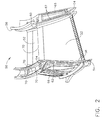
- FIGS 2 and 3 are perspective views of an exemplary turbine nozzle assembly 50 that may be used with a gas turbine engine, such as engine 10 (shown in Figure 1).
- nozzle assembly 50 includes two airfoils 52 and 53 and is generally known as a doublet.
- a plurality of turbine nozzle assemblies 50 are circumferentially coupled together to form a turbine nozzle ring (not shown).
- doublet 50 includes a plurality of circumferentially-spaced airfoils 52 and 53 coupled together by an arcuate radially outer band or platform 54, and an arcuate radially inner band or platform 56.
- each band 54 and 56 is integrally-formed with airfoils 52 and 53, and each doublet 50 includes two airfoils 52 and 53.
- a nozzle assembly that includes three airfoils, such as airfoils 52 and 53 and another airfoil (not shown), is generally known as a triplet.
- outer band 54 includes a radially inner surface 58 and inner band 56 includes a radially inner surface 60. Inner surfaces 58 and 60 define a flow path for combustion gases to flow through turbine nozzle assembly 50.
- Nozzle assembly 50 also includes a pair of opposite and axially-extending faces 66 and 68 that each include one or more axial spline seal slots 62 and one or more radial spline seal slots 64.
- turbine nozzle assembly 50 includes one or more datums 70 (some of which may not be shown and/or labeled with reference numeral 70) to facilitate positioning turbine nozzle assembly 50 for a manufacturing process, as will be described in more detail below.
- datums 70 are exemplary only.
- turbine nozzle assembly 50 may include any number of datums that are each positioned anywhere on turbine nozzle assembly 50 that enable the datums to function as described herein.
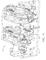
- FIGS 4 and 5 are perspective views of an exemplary embodiment of a fixture assembly 100 for use in manufacturing a component.
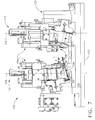
- Figures 6 and 7 are side views of fixture assembly 100.
- fixture assembly 100 may be used to manufacture any component, for example components of any operable shape, size, configuration, and/or material(s), in the exemplary embodiment fixture assembly 100 is used in manufacturing turbine nozzle assembly 50 (shown in Figures 2 and 3).
- turbine nozzle assembly 50 shown in Figures 2 and 3
- the specific size, shape, and/or configuration of fixture assembly 100 described and/or illustrated herein is exemplary only. Accordingly, the specific size, shape, and/or configuration of fixture assembly 100 generally, as well as portions thereof, may be selected to accommodate other components than turbine nozzle assembly 50.
- Fixture assembly 100 generally includes a base 102, two fixtures 104, and one or more clamps 106 coupled to each fixture 104.
- Fixture assembly 100 may be positioned adjacent a machining tool (not shown) and/or an inspection tool (not shown) for machining and/or inspecting various surfaces of turbine nozzle assembly 50, such as, in the exemplary embodiment, spline seal slots 62 and/or radial spline seal slots 64.
- a machining tool not shown
- an inspection tool for machining and/or inspecting various surfaces of turbine nozzle assembly 50, such as, in the exemplary embodiment, spline seal slots 62 and/or radial spline seal slots 64.
- the specific size, shape, and/or configuration of fixture assembly 100 generally, as well as portions thereof, may be selected to align, support, and/or fixedly secure turbine nozzle assembly 50 in orientations that accommodate machining and/or inspecting other turbine nozzle assembly surfaces than slots 62 and/or 64.
- fixture assembly 100 includes two fixtures 104.
- a turbine nozzle assembly 50 can be coupled to one of fixtures 104 such that face 66 can be positioned to be inspected and/or machined, and the assembly 50 can be coupled to the other fixture 104 such that face 68 can be positioned to be machined and/or inspected.
- fixture assembly 100 is illustrated as including two fixtures 104, fixture assembly 100 may include any number of fixtures 104.
- Fixtures 104 each include a plurality of supporting surfaces 107 (some of which may not be shown and/or labeled with reference numeral 107) for supporting turbine nozzle assembly 50 relative to fixture 104.
- supporting surfaces 107 are exemplary only.
- fixtures 104 may each include any number of supporting surfaces that are each positioned anywhere on fixture 104 that enable the supporting surfaces to function as described herein.
- fixtures 104 each include a plurality of datum location points 108 (some of which may not be shown and/or labeled with reference numeral 108) for locating turbine nozzle assembly datums 70.
- turbine nozzle assembly 50 is located and orientated relative to fixture 104 for machining and/or inspecting slots 62 and 64 using a machining and/or inspecting tool adjacent fixture assembly 100, as will be described in more detail below.
- datum location points 108 are exemplary only.
- fixtures 104 may each include any number of datum location points that are each positioned anywhere on fixture 104 that enable the datum location points to function as described herein.
- Clamp(s) 106 each facilitate coupling turbine nozzle assembly 50 to fixture 104 by applying force thereto.
- clamp 106 is movable between a position (not shown) allowing turbine nozzle assembly 50 to be positioned on fixture 104 without interference from clamp 106, and a position (shown in Figures 4-7) wherein clamp 106 applies force to turbine nozzle assembly 50 to facilitate fixedly securing turbine nozzle assembly 50 to fixture 104 such that turbine nozzle assembly datums 70 are aligned with datum location points 108.
- Clamp(s) 106 may each be moved using any suitable means, such as, but not limited to, hydraulic, electrical, and/or pneumatic power. In some embodiments, clamp(s) 106 may each be or include a biasing mechanism.
- Clamp(s) 106 may each have any suitable size and/or shape that enable clamp(s) 106 to function as described herein.
- clamp(s) 106 may each have any suitable size and/or shape for engaging and applying force to any portion of turbine nozzle assembly 50, whether such size, shape, portion, and/or engagement is described and/or illustrated herein.
- Fixtures 104 may each include other clamps that facilitate fixedly securing turbine nozzle assembly 50 to fixture 104 such that turbine nozzle assembly datums 70 are aligned with datum location points 108, but that are not described, illustrated, and/or labeled with a reference numeral herein.
- Fixtures 104 are rotatably coupled to base 102 for rotation with respect to base 102 between a position 110 (shown in Figures 4 and 7) that facilitates coupling turbine nozzle assembly 50 to fixture 104 and a position 112 (shown in Figures 5 and 6) that facilitates performing a manufacturing process on turbine nozzle assembly 50.
- position 110 may facilitate loading and/or unloading of turbine nozzle 50 from fixture 104.
- position 110 may facilitate easier positioning, as compared with some known fixtures, of turbine nozzle assembly datums 70 adjacent fixture datum location points 108 such that datums 70 are each aligned with the corresponding location point 108 because portions of fixture 104 are more accessible in position 110 than in the position 112 that facilitates performing a manufacturing process on assembly 50.
- position 110 may facilitate inspecting a position of turbine nozzle assembly 50 relative to fixture 104.
- position 112 may facilitate performing a manufacturing process on turbine nozzle assembly 50.
- position 112 may facilitate positioning turbine nozzle assembly 50 adjacent, and/or in a path of, a machining tool (not shown) and/or an inspection tool (not shown) for machining and/or inspecting various surfaces of turbine nozzle assembly 50, such as, but not limited to, in the exemplary embodiment spline seal slots 62 and/or radial spline seal slots 64.
- Position 110 may be any angular position relative to base 104 that facilitates coupling turbine nozzle assembly 50 to fixture 104 and/or inspecting a position of assembly 50 relative to fixture 104.
- base 102 includes a generally horizontal surface 114 and, when in position 110, a central longitudinal axis 116 of each fixture 104 is generally parallel to surface 114, as shown in Figures 5 and 6.
- position 112 may be any angular position relative to base 104 that facilitates performing a manufacturing process on turbine nozzle assembly 50.
- each fixture 104 when in position 112, central longitudinal axis 116 of each fixture 104 is generally perpendicular to surface 114, as shown in Figures 4 and 7.
- fixtures 104 may each be rotated an any angular distance between positions 110 and 112 that enables positions 110 and 112 to function as described herein.
- positions 110 and 112 may be separated by other angular distances, in the exemplary embodiment positions 110 and 112 are separated by about 90° of rotation.
- Fixtures 104 may be rotatably coupled to base 102 using any suitable structure and/or means, such as, but not limited to, rotary bearings (not shown in Figures 4-7).
- fixture assembly 100 includes an actuator 118 that is coupled to base 102 and fixtures 104 for rotating fixtures 104 relative to base 102.
- Actuator 118 may rotate fixtures 104 using any suitable means, such as, but not limited to, hydraulic, electrical, and/or pneumatic power. Additionally or alternatively, fixtures 104 are rotated manually by an operator.
- fixture assembly 100 may include any suitable locking device (not shown) that fixedly secured fixtures 104 in positions 110 and 112 such that fixtures 104 generally remain in position 110 during coupling of a turbine nozzle assembly 50 thereto (and/or during inspection of a position of an assembly 50 relative to a fixture 104) and such that fixtures 104 generally remain in position 112 while a manufacturing process is performed on assembly 50.
- fixture assembly 100 may include any suitable device (whether the locking device) that facilitates preventing rotation of fixtures 104 past positions 110 and 112.
- fixture assembly 100 includes a rack and pinion device 120 that includes an indexer 122 and a index-plate 124, as shown in Figure 8, to facilitate locking fixtures 104 into positions 110 and 112 and/or to facilitate preventing rotation of fixtures 104 past positions 110 and 112.
- rack and pinion device 120 that includes an indexer 122 and a index-plate 124, as shown in Figure 8, to facilitate locking fixtures 104 into positions 110 and 112 and/or to facilitate preventing rotation of fixtures 104 past positions 110 and 112.
- fixtures 104 are rotated to position 110 and a turbine nozzle assembly 50 is coupled thereto, for example as described above, such that turbine nozzle datums 70 are each aligned with their corresponding datum location points 108.
- a position of a turbine nozzle assembly 50 relative to a fixture 104 is inspected when fixtures 104 are in position 110.
- a shim is inserted between one or more turbine nozzle assembly datums 70 and the corresponding datum location point 108 to determine a distance between the datum(s) 70 and the corresponding datum location point(s) 108.
- a turbine nozzle 50 is coupled to a fixture 104 (and in some embodiments a position of an assembly 50 is inspected relative to a fixture 104), fixtures 104 rotated into position 112 and a manufacturing process is performed on one or more turbine nozzle assemblies 50 that are coupled to the fixtures 104.
- spline seal slots 62 and/or radial spline seal slots 64 are machined within assemblies 50.
- fixture assembly 100 may facilitate accurately manufacturing a component, and may facilitate reducing a cycle time of manufacturing the component, thereby possibly reducing an overall cost of manufacturing the component. Specifically, by being rotatable between a position that facilitates coupling the component to the fixture and a position that facilitates performing a manufacturing process on the component, fixture assembly 100 may facilitate easier loading and/or unloading of the component from the fixture, as compared with some known fixtures. Moreover, fixture assembly 100 may facilitate easier inspecting of a position of the component relative to the fixture, as compared with some known fixtures. Accordingly, loading and/or unloading of the component from the fixture, and/or inspection of a position of the component relative to the fixture, may possibly be accomplished in less time and without specialized operator training.
- a repeatability of manufacturing the component may be increased, while a cycle time of manufacturing the component may be reduced.
- fixture assembly facilitates ensuring that the component is positioned in a predetermined position relative to a manufacturing tool, which may increase a repeatability of manufacturing the component.
- assemblies and methods described and/or illustrated herein are described and/or illustrated with respect to gas turbine engine components, and more specifically a turbine nozzle assembly for a gas turbine engine, practice of the assemblies and methods described and/or illustrated herein is not limited to turbine nozzle assemblies, nor gas turbine engine components generally. Rather, the assemblies and methods described and/or illustrated herein are applicable to any component and/or any manufacturing process.
- assemblies and methods are described and/or illustrated herein in detail.
- the assemblies and methods are not limited to the specific embodiments described herein, but rather, components of each member and components of each assembly, as well as steps of each method, may be utilized independently and separately from other components and steps described herein.
- Each component, and each method step can also be used in combination with other components and/or method steps.
Landscapes
- Engineering & Computer Science (AREA)
- Mechanical Engineering (AREA)
- Turbine Rotor Nozzle Sealing (AREA)
Applications Claiming Priority (1)
| Application Number | Priority Date | Filing Date | Title |
|---|---|---|---|
| US11/336,002 US7918024B2 (en) | 2006-01-20 | 2006-01-20 | Methods and apparatus for manufacturing components |
Publications (2)
| Publication Number | Publication Date |
|---|---|
| EP1810779A2 true EP1810779A2 (de) | 2007-07-25 |
| EP1810779A3 EP1810779A3 (de) | 2013-09-04 |
Family
ID=37896052
Family Applications (1)
| Application Number | Title | Priority Date | Filing Date |
|---|---|---|---|
| EP07100615.9A Withdrawn EP1810779A3 (de) | 2006-01-20 | 2007-01-16 | Verfahren und Vorrichtung zum Herstellen von Bauteilen |
Country Status (3)
| Country | Link |
|---|---|
| US (1) | US7918024B2 (de) |
| EP (1) | EP1810779A3 (de) |
| JP (1) | JP5295504B2 (de) |
Cited By (2)
| Publication number | Priority date | Publication date | Assignee | Title |
|---|---|---|---|---|
| FR2985676A1 (fr) * | 2012-01-18 | 2013-07-19 | Peugeot Citroen Automobiles Sa | Dispositif de manutention de pieces comportant un plateau mobile |
| DE102008044446B4 (de) | 2007-08-27 | 2019-03-28 | General Electric Company | Verschweisste Leitapparatanordnung für eine Dampfturbine und verwandte Montagevorrichtungen |
Families Citing this family (3)
| Publication number | Priority date | Publication date | Assignee | Title |
|---|---|---|---|---|
| US9011079B2 (en) * | 2012-01-09 | 2015-04-21 | General Electric Company | Turbine nozzle compartmentalized cooling system |
| US9133724B2 (en) | 2012-01-09 | 2015-09-15 | General Electric Company | Turbomachine component including a cover plate |
| JP6466720B2 (ja) * | 2015-01-22 | 2019-02-06 | 中電プラント株式会社 | 静翼ブロック取付用治具 |
Citations (5)
| Publication number | Priority date | Publication date | Assignee | Title |
|---|---|---|---|---|
| DE19547952A1 (de) * | 1995-12-21 | 1997-06-26 | Goetz Metall Anlagen | Spannvorrichtung zum Spannen von Werkstücken mit beliebiger Umfangskontur |
| US6186867B1 (en) * | 1996-04-30 | 2001-02-13 | United Technologies Corporation | Method for manufacturing precisely shaped parts |
| DE10058675A1 (de) * | 2000-11-25 | 2002-06-06 | Schunk Gmbh & Co Kg | Spannvorrichtung zum Spannen von Läuferschaufeln |
| US6560890B1 (en) * | 2002-02-21 | 2003-05-13 | General Electric Company | Fixture for locating and clamping a part for laser drilling |
| US20050268461A1 (en) * | 2004-06-07 | 2005-12-08 | Ouellette Randall M | Method and apparatus for securing turbine components for manufacture |
Family Cites Families (22)
| Publication number | Priority date | Publication date | Assignee | Title |
|---|---|---|---|---|
| US2143462A (en) * | 1936-07-30 | 1939-01-10 | Westinghouse Electric & Mfg Co | Method of manufacturing turbine diaphragms |
| US2488296A (en) * | 1946-06-03 | 1949-11-15 | Lee J Drennan Inc | Work support |
| US3566068A (en) * | 1968-08-29 | 1971-02-23 | Russ L Bruneri | Apparatus for aligning and arc-removing turbine nozzle vanes |
| US3920947A (en) | 1972-01-27 | 1975-11-18 | Chromalloy American Corp | Turbine-nozzle manufacturing apparatus and method |
| US3963894A (en) | 1974-01-24 | 1976-06-15 | Chromalloy American Corporation | Turbine-nozzle manufacturing apparatus |
| GB2075057B (en) | 1980-05-01 | 1984-03-07 | Rolls Royce | Nickel base superalloy |
| JPH02145240A (ja) * | 1988-11-29 | 1990-06-04 | Nachi Fujikoshi Corp | 回転割り出し盤の衝撃吸収装置 |
| US5174715A (en) * | 1990-12-13 | 1992-12-29 | General Electric Company | Turbine nozzle |
| JPH0740101A (ja) * | 1993-07-26 | 1995-02-10 | Okuma Mach Works Ltd | Nc多軸自動盤のワーク搬送装置 |
| US5492050A (en) * | 1994-02-14 | 1996-02-20 | Holtgraver; Edward G. | Pneumatic actuator with rack and pinion assembly |
| DE19813958C1 (de) | 1998-03-28 | 1999-11-25 | Mtu Muenchen Gmbh | Verfahren zum Herstellen eines gebauten Leitkranzes einer Gasturbine, insbesondere eines Flugtriebwerkes, sowie ein nach dem Verfahren hergestellter Leitkranz |
| US6183193B1 (en) | 1999-05-21 | 2001-02-06 | Pratt & Whitney Canada Corp. | Cast on-board injection nozzle with adjustable flow area |
| JP4056179B2 (ja) * | 1999-08-06 | 2008-03-05 | 三菱重工業株式会社 | 重心位置計測装置 |
| JP4437515B2 (ja) * | 2000-08-01 | 2010-03-24 | 株式会社Ihi | タービンノズルの製造方法 |
| US6855033B2 (en) * | 2001-12-13 | 2005-02-15 | General Electric Company | Fixture for clamping a gas turbine component blank and its use in shaping the gas turbine component blank |
| US6915636B2 (en) | 2002-07-15 | 2005-07-12 | Power Systems Mfg., Llc | Dual fuel fin mixer secondary fuel nozzle |
| US7080434B2 (en) * | 2003-06-06 | 2006-07-25 | General Electric Company | Fixture having integrated datum locators |
| US6886346B2 (en) | 2003-08-20 | 2005-05-03 | Power Systems Mfg., Llc | Gas turbine fuel pilot nozzle |
| US7034262B2 (en) * | 2004-03-23 | 2006-04-25 | General Electric Company | Apparatus and methods for repairing tenons on turbine buckets |
| US7503113B2 (en) * | 2005-10-13 | 2009-03-17 | Siemens Energy, Inc. | Turbine vane airfoil reconfiguration system |
| US7575415B2 (en) * | 2005-11-10 | 2009-08-18 | General Electric Company | Methods and apparatus for assembling turbine engines |
| US7635119B1 (en) * | 2008-06-04 | 2009-12-22 | United Technologies Corporation | Adjustable leveling mount |
-
2006
- 2006-01-20 US US11/336,002 patent/US7918024B2/en not_active Expired - Fee Related
-
2007
- 2007-01-16 EP EP07100615.9A patent/EP1810779A3/de not_active Withdrawn
- 2007-01-19 JP JP2007009727A patent/JP5295504B2/ja not_active Expired - Fee Related
Patent Citations (5)
| Publication number | Priority date | Publication date | Assignee | Title |
|---|---|---|---|---|
| DE19547952A1 (de) * | 1995-12-21 | 1997-06-26 | Goetz Metall Anlagen | Spannvorrichtung zum Spannen von Werkstücken mit beliebiger Umfangskontur |
| US6186867B1 (en) * | 1996-04-30 | 2001-02-13 | United Technologies Corporation | Method for manufacturing precisely shaped parts |
| DE10058675A1 (de) * | 2000-11-25 | 2002-06-06 | Schunk Gmbh & Co Kg | Spannvorrichtung zum Spannen von Läuferschaufeln |
| US6560890B1 (en) * | 2002-02-21 | 2003-05-13 | General Electric Company | Fixture for locating and clamping a part for laser drilling |
| US20050268461A1 (en) * | 2004-06-07 | 2005-12-08 | Ouellette Randall M | Method and apparatus for securing turbine components for manufacture |
Cited By (2)
| Publication number | Priority date | Publication date | Assignee | Title |
|---|---|---|---|---|
| DE102008044446B4 (de) | 2007-08-27 | 2019-03-28 | General Electric Company | Verschweisste Leitapparatanordnung für eine Dampfturbine und verwandte Montagevorrichtungen |
| FR2985676A1 (fr) * | 2012-01-18 | 2013-07-19 | Peugeot Citroen Automobiles Sa | Dispositif de manutention de pieces comportant un plateau mobile |
Also Published As
| Publication number | Publication date |
|---|---|
| JP5295504B2 (ja) | 2013-09-18 |
| EP1810779A3 (de) | 2013-09-04 |
| US20070169344A1 (en) | 2007-07-26 |
| JP2007192225A (ja) | 2007-08-02 |
| US7918024B2 (en) | 2011-04-05 |
Similar Documents
| Publication | Publication Date | Title |
|---|---|---|
| US6842995B2 (en) | Methods and apparatus for aligning components for inspection | |
| US7178255B1 (en) | Methods and apparatus for manufacturing components | |
| US7752755B2 (en) | Methods and apparatus for manufacturing components | |
| CN107866685B (zh) | 用于处理燃气涡轮发动机的构件的工具夹具组件 | |
| US6886422B2 (en) | Methods and apparatus for inspecting components | |
| US9623492B2 (en) | Milling tool for portion of slot in rotor | |
| US6968608B2 (en) | Method and apparatus to decrease combustor emissions | |
| EP2816430B1 (de) | Verfahren zur Endbearbeitung einer Klinge | |
| CN109416117B (zh) | 组装行星架的方法 | |
| US20060156544A1 (en) | Method and apparatus to remove material from a turbine wheel in-situ | |
| US20070119040A1 (en) | Methods and apparatus for securing components for manufacture | |
| US7918024B2 (en) | Methods and apparatus for manufacturing components | |
| US20060059676A1 (en) | Fixture having integrated datum locators | |
| WO2013138055A1 (en) | Apparatus and method for servicing turbomachinery components in-situ | |
| EP0890410B1 (de) | Ein Rohling und eine Vorrichtung zum Herstellen von präzisen Formteilen | |
| CA2902552A1 (en) | System and method for automated machining of toothed members | |
| US5182855A (en) | Turbine nozzle manufacturing method | |
| JP7053142B2 (ja) | 携帯型ミル工具および、ミル処理する方法 | |
| KR101513481B1 (ko) | 가스터빈 압축기의 디스크 고정 지그 및 이를 이용한 디스크의 가공방법 | |
| EP3943876B1 (de) | Verfahren zur messung der teilegrösse und des auslaufs | |
| CN113967857A (zh) | 一种涡轮前封严盘变形修复的加工方法 | |
| JP3454030B2 (ja) | シリンダヘッドの加工方法 |
Legal Events
| Date | Code | Title | Description |
|---|---|---|---|
| PUAI | Public reference made under article 153(3) epc to a published international application that has entered the european phase |
Free format text: ORIGINAL CODE: 0009012 |
|
| AK | Designated contracting states |
Kind code of ref document: A2 Designated state(s): AT BE BG CH CY CZ DE DK EE ES FI FR GB GR HU IE IS IT LI LT LU LV MC NL PL PT RO SE SI SK TR |
|
| AX | Request for extension of the european patent |
Extension state: AL BA HR MK YU |
|
| RIC1 | Information provided on ipc code assigned before grant |
Ipc: F01D 25/28 20060101ALI20130328BHEP Ipc: B23Q 3/06 20060101ALI20130328BHEP Ipc: B23Q 3/18 20060101AFI20130328BHEP |
|
| PUAL | Search report despatched |
Free format text: ORIGINAL CODE: 0009013 |
|
| AK | Designated contracting states |
Kind code of ref document: A3 Designated state(s): AT BE BG CH CY CZ DE DK EE ES FI FR GB GR HU IE IS IT LI LT LU LV MC NL PL PT RO SE SI SK TR |
|
| AX | Request for extension of the european patent |
Extension state: AL BA HR MK RS |
|
| RIC1 | Information provided on ipc code assigned before grant |
Ipc: B23Q 3/06 20060101ALI20130731BHEP Ipc: B23Q 3/18 20060101AFI20130731BHEP Ipc: F01D 25/28 20060101ALI20130731BHEP |
|
| 17P | Request for examination filed |
Effective date: 20140304 |
|
| RBV | Designated contracting states (corrected) |
Designated state(s): AT BE BG CH CY CZ DE DK EE ES FI FR GB GR HU IE IS IT LI LT LU LV MC NL PL PT RO SE SI SK TR |
|
| 17Q | First examination report despatched |
Effective date: 20140328 |
|
| AKX | Designation fees paid |
Designated state(s): DE FR GB |
|
| STAA | Information on the status of an ep patent application or granted ep patent |
Free format text: STATUS: THE APPLICATION IS DEEMED TO BE WITHDRAWN |
|
| 18D | Application deemed to be withdrawn |
Effective date: 20140808 |