EP1808796A2 - RFID-Leser und RFID-System - Google Patents
RFID-Leser und RFID-System Download PDFInfo
- Publication number
- EP1808796A2 EP1808796A2 EP06124045A EP06124045A EP1808796A2 EP 1808796 A2 EP1808796 A2 EP 1808796A2 EP 06124045 A EP06124045 A EP 06124045A EP 06124045 A EP06124045 A EP 06124045A EP 1808796 A2 EP1808796 A2 EP 1808796A2
- Authority
- EP
- European Patent Office
- Prior art keywords
- frequency
- reader
- rfid
- signal
- offset
- Prior art date
- Legal status (The legal status is an assumption and is not a legal conclusion. Google has not performed a legal analysis and makes no representation as to the accuracy of the status listed.)
- Granted
Links
Images

Classifications
-
- G—PHYSICS
- G06—COMPUTING OR CALCULATING; COUNTING
- G06K—GRAPHICAL DATA READING; PRESENTATION OF DATA; RECORD CARRIERS; HANDLING RECORD CARRIERS
- G06K7/00—Methods or arrangements for sensing record carriers, e.g. for reading patterns
- G06K7/0008—General problems related to the reading of electronic memory record carriers, independent of its reading method, e.g. power transfer
-
- H—ELECTRICITY
- H04—ELECTRIC COMMUNICATION TECHNIQUE
- H04B—TRANSMISSION
- H04B7/00—Radio transmission systems, i.e. using radiation field
- H04B7/24—Radio transmission systems, i.e. using radiation field for communication between two or more posts
- H04B7/26—Radio transmission systems, i.e. using radiation field for communication between two or more posts at least one of which is mobile
- H04B7/2612—Arrangements for wireless medium access control, e.g. by allocating physical layer transmission capacity
Definitions
- the present invention relates to a reader for radio frequency identification (RFID) and a RFID system, and more particularly, to a reader for RFID and a RFID system improved in reception for RFID using a listen before talk (LBT) mode.
- RFID radio frequency identification
- LBT listen before talk
- Bar codes have been commonly and widely used to identify books, records or other related items in libraries and consumer items in supermarkets. Although bar codes can be readily implemented at low cost, they usually have a short read distance and are not reusable. Also, when reading, a reader has to be precisely placed on a bar code-printed surface, and if bar codes are damaged, it is impossible to read the bar codes. Thus, an RFID system is developed to overcome these limitations.
- a typical RFID system can read and write wirelessly. Thus, a direct contact or scanning within a visible band is not necessary. Also, many books, records or other items can be identified at the same time in any position or direction. Since electronic tags used in the RFID system have a nearly permanent lifetime, it has been highlighted as an effective tool to establish a ubiquitous system.
- An RFID system identifies identification (ID) information on electronic tags that are adhered to items via wireless telecommunications.
- ID identification
- RFID is a combined technology of using electromagnetism or static electricity coupling within a frequency of an electromagnetic spectrum.
- an RFID system Due to RFID standardization, decrease in a unit cost and a widened readable distance, an RFID system has been broadly used in various industrial fields.
- FIG. 1 illustrates the configuration of a typical RFID system 100.
- the RFID system 100 includes a reader 120 for RFID and an electronic tag 110 with a built-in antenna (not shown).
- the reader 120 for RFID continuously sends out electromagnetic waves with a certain frequency.
- the electronic tag 110 is wirelessly supplied with power when displaced within a frequency operation range of the reader 120 and becomes activated.
- the reader 120 for RFID uses a radio frequency to transmit a signal for activating the electronic tag 110.
- the electronic tag 110 is activated, data incorporated within the electronic tag 110 are transmitted to the reader 120 through the antenna.
- the electronic tag 110 activated by the supplied power waits for an instruction from the reader 120. If a correct instruction is received, data are transmitted to the reader 120 in response to the receipt.
- the reader 120 may transmit data based on an LBT mode or a frequency hopping spread spectrum (FHSS) mode.
- FHSS frequency hopping spread spectrum
- An LBT mode is used to avoid an interference between the readers 120. Even though the readers 120 are apart several kilometers away from each other, they may affect each other because the reader 120 has a longer read distance than the electronic tag 110. More specifically, according to the LBT mode, the reader 120 scans a channel that is used prior to the transmission, and transmits data using a channel that is not used to thereby minimize the interference.
- the LBT mode is a method of detecting the channel that is not used during the scanning.
- the reader uses a direct conversion method to minimize the power consumption and the size of the reader.
- the direct conversion method needs to remove direct current (DC) offset.
- the present invention is directed to solve at least the problems and disadvantages of the background art.
- the present invention is directed to provide a reader for RFID that can minimize decrease in power of an input frequency so as to allow measuring a level of occupied power of a channel that is used during execution of an LBT mode.
- a reader for RFID receiving a channel signal comprising a frequency oscillator generating an oscillating signal at a frequency that is offset by an offset frequency from a center frequency of the channel signal, a mixer mixing the channel signal with the oscillating signal that is offset, and a filer filtering a mixed frequency signal provided from the mixer.
- the filter may comprise a direct current cut-off band that cuts off a DC component of the mixed frequency signal and a pass band at which the mixed frequency passes through.
- the DC cut-off band may include a cut-off frequency less than the offset frequency.
- the pass band includes a cut-off frequency less than a frequency obtained by adding one half of a band of the channel signal and the offset frequency.
- the reader for RFID may further comprise a compensator compensating the intensity of a frequency signal filtered at the filter.
- the compensator comprises an analog-to-digital converter converting the frequency signal filtered at the filter into a digital code, and an intensity indicator mapping the received frequency signal from the analog-to-digital converter with reference to the digital code converted at the analog-to-digital converter.
- the channel signal may be a signal to execute an LBT (listen before talk) mode.
- the offset frequency is greater than approximately 10 KHz and less than one half of the channel signal band.
- the received signal has a band ranging from approximately 908.5 MHz to 914 MHz.
- a RFID system comprising a reader for RFID, and an electronic tag.
- FIG. 2 illustrates the configuration of a reader 200 for RFID according to an embodiment of the present invention.
- the reader 200 includes a frequency oscillator 201, a mixer 202 and a filter 203.
- An output terminal of the frequency oscillator 201 is coupled to a second input terminal of the mixer 202.
- a channel signal IN is inputted to a first input terminal of the mixer 202.
- An output terminal of the mixer 202 is coupled to an input terminal of the filter 203.
- a filter frequency is outputted through an output terminal of the filter 203.
- the reader 200 scans power of a channel that is used and checks which channel is to be used for data transmission. That is, the reader 200 uses an LBT mode to detect a channel that is not used.
- a receipt band of the reader 200 ranging from approximately 908.5 MHz to 914 MHz includes about 27 channels.
- Each of the channels has a bandwidth of approximately 200 KHz, and a guard band employed to distinguish the individual channels is approximately 50 KHz.
- the reader 200 receives power of the channel signal IN having the center at f 1 .
- the frequency oscillator 201 oscillates an oscillating frequency f 2 as defined in the following equation.
- f 2 f 1 + ⁇ f
- f 1 , f 2 and ⁇ f represent a center frequency of the channel signal IN, an oscillating frequency and an offset frequency, respectively.
- the frequency oscillator 201 oscillates an oscillating frequency f 2 that is offset by the offset frequency ⁇ f from the center frequency f 1 .
- the oscillating frequency f 2 oscillated at the frequency oscillator 201 is supplied to the second input terminal of the mixer 202.
- the frequency is to be up converted or down converted at the mixer 202.
- a frequency obtained by adding the center frequency f 1 and the oscillating frequency f 2 is outputted through the output terminal of the mixer 202.
- the mixer 202 includes a down-conversion mixer, and outputs a mixed frequency f mix as defined in the equation below.
- f mix f 1 - f 2
- f mix , f 1 and f 2 represent a frequency mixed at the mixer 202, the center frequency of the channel signal IN and the oscillating frequency, respectively.
- the oscillating frequency f 2 is an added value of f 1 + ⁇ f.
- f mix , f 1 , f 2 , and ⁇ f represent the frequency mixed at the mixer 202, the center frequency of the channel signal IN, the oscillating frequency, and the offset frequency, respectively.
- the frequency mixed at the mixer 202 is offset as much as the offset frequency ⁇ f.
- the mixed frequency f mix is inputted to the filter 203.
- the filter 203 filters the mixed frequency f mix that is offset as much as the offset frequency ⁇ f.
- the reader 200 is a direct conversion type receiver, and thus, removing DC offset of the received channel signal IN is necessary.
- the filter 203 removes a DC component of the mixed frequency f mix by a DC cut-off band f cut-off .
- the filter 203 is designed to filter a specific frequency band f pass to detect the power of the mixed frequency f mix .
- f specific frequency band
- the filter 203 filters the specific frequency band f pass to correct an error in detecting the power of the channel signal IN.
- the specific frequency band f pass passing through the filter 203 is variable.
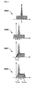
- FIG. 3 illustrates exemplary spectrums to describe the power detection operations of the channel signal by the reader according to the embodiment of present invention.
- the reader 200 receives the channel signal IN.
- the reader 200 offsets the center frequency f 1 of the received channel signal IN by the offset frequency ⁇ f.
- the reader 200 removes a DC component of the offset frequency ⁇ f. Because the reader 200 is a direct down-conversion type receiver, the DC component needs to be removed. More specifically, the filter 203 has a DC cut-off band f cut-off and removes the DC component.
- the power of the channel signal IN can be detected without difficulty when the DC component is removed through the filtering.
- the reader 200 filters a certain band of the channel signal IN to detect the power of the channel signal IN.
- the reader 200 receives channel signals, each generated at 27 channels having a band ranging from approximately 908.5 MHz to 914 MHz.
- a guard band is placed between the individual channels.
- Each of the channel signals may include signals from an electronic tag or signals transmitted from another reader.
- a bandwidth of each of the channel signals is approximately 200K Hz, and the guard band is approximately 50 KHz.
- Signals of adjacent channels to the target channel may be detected while a frequency oscillated from the frequency oscillator 201 and the channel signal IN inputted to the reader 200 are mixed.
- the reader 200 may not accurately detect the power of the target channel to be checked by the reader 200.
- the reader 200 needs to have a preset pass band that allows filtering of the channel signal IN with the changed center frequency in order to prevent interference from the adjacent channels.
- the pass band is generated variably, and as mentioned above, the pass band plays a role in blocking the interference between the signals from the adjacent channels.
- the cut-off frequency of the DC cuff-off band f cut-off is less than the offset frequency ⁇ f.
- the cut-off frequency of the pass band f pass is less than a frequency obtained by adding the offset frequency ⁇ f and one half of the band at which the channel signal IN is allocated.
- the offset frequency ⁇ f is greater than approximately 10 KHz but less than one half of the band at which channel signal IN is allocated.
- the power of the channel signal received at the reader 200 for RFID can be accurately detected.
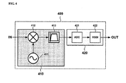
- FIG. 4 illustrates the configuration of a reader 400 according to another embodiment of the present invention.
- the reader 400 that is modified from the reader 200 according to the first described embodiment includes a receiver 410 and a compensator 420.
- An output of the receiver 410 is inputted to an input terminal of an analog-to-digital converter 421.
- An output of the analog-to-digital converter 421 is inputted to an input terminal of an intensity indicator 422.
- An output signal of the receiver 410 is converted into a digital code using the analog-to-digital converter 421.
- the intensity indicator 422 maps the intensity of the received signal using the digital code.
- the intensity indicator 422 maps the digital code using an experimentally measured value.
- the power of the channel signal IN When the power of the channel signal IN is detected, the power of adjacent channels is not detected. Since channel signal IN to be detected has a small offset, the power of the target channel signal IN can be easily detected.
- the reader 400 can compensate for the power that is lowered as the channel signal IN is filtered through the analog-to-digital conversion. As a result, accurate and fast detection can be achieved.
- a frequency even with low power that is received at a channel can be easily identified using a reader for RFID that can minimize decrease in the power of a received frequency.
- the reader can be minimized, and the power consumption can be reduced.
Landscapes
- Engineering & Computer Science (AREA)
- Artificial Intelligence (AREA)
- Computer Vision & Pattern Recognition (AREA)
- Physics & Mathematics (AREA)
- General Physics & Mathematics (AREA)
- Theoretical Computer Science (AREA)
- Computer Networks & Wireless Communication (AREA)
- Signal Processing (AREA)
- Near-Field Transmission Systems (AREA)
- Superheterodyne Receivers (AREA)
- Circuits Of Receivers In General (AREA)
Applications Claiming Priority (1)
| Application Number | Priority Date | Filing Date | Title |
|---|---|---|---|
| KR1020060004789A KR100666338B1 (ko) | 2006-01-17 | 2006-01-17 | 전파식별용 리더기 및 전파식별 시스템. |
Publications (3)
| Publication Number | Publication Date |
|---|---|
| EP1808796A2 true EP1808796A2 (de) | 2007-07-18 |
| EP1808796A3 EP1808796A3 (de) | 2008-12-10 |
| EP1808796B1 EP1808796B1 (de) | 2009-10-07 |
Family
ID=37867362
Family Applications (1)
| Application Number | Title | Priority Date | Filing Date |
|---|---|---|---|
| EP06124045A Not-in-force EP1808796B1 (de) | 2006-01-17 | 2006-11-14 | RFID-Leser und RFID-System |
Country Status (5)
| Country | Link |
|---|---|
| US (1) | US20070176747A1 (de) |
| EP (1) | EP1808796B1 (de) |
| JP (1) | JP4303744B2 (de) |
| KR (1) | KR100666338B1 (de) |
| CN (1) | CN100576228C (de) |
Families Citing this family (7)
| Publication number | Priority date | Publication date | Assignee | Title |
|---|---|---|---|---|
| KR100717881B1 (ko) | 2005-09-23 | 2007-05-14 | 한국전자통신연구원 | 모바일 rfⅰd 리더 및 그 제어 방법 |
| KR101372060B1 (ko) * | 2007-01-30 | 2014-03-07 | 엘지이노텍 주식회사 | 변조주파수 다중화를 이용한 rfid 수신 시스템 |
| KR100932902B1 (ko) * | 2007-08-29 | 2009-12-21 | 한국전자통신연구원 | 이중 감도 모드를 갖는 리더 간 통신 방법 및 장치 |
| CN101561864B (zh) * | 2009-03-12 | 2011-05-18 | 上海秀派电子科技有限公司 | 信息交互装置 |
| JP6587259B2 (ja) | 2015-04-10 | 2019-10-09 | ゼットティーイー コーポレイション | アンライセンス搬送波の競争方法及び装置 |
| DE112018004801T5 (de) | 2017-08-30 | 2020-06-18 | Cummins Filtration Ip, Inc. | Sperrvorrichtung zur erkennung von originalfiltern |
| CN111405383B (zh) * | 2019-09-30 | 2021-09-28 | 浙江利尔达物芯科技有限公司 | 一种基于LBT的KR920-923MHz的LoRaWAN物联网网关 |
Family Cites Families (31)
| Publication number | Priority date | Publication date | Assignee | Title |
|---|---|---|---|---|
| GB2106359B (en) * | 1981-09-24 | 1985-07-03 | Standard Telephones Cables Ltd | Direct conversion radio receiver for fm signals |
| GB2158330A (en) * | 1984-04-30 | 1985-11-06 | Philips Electronic Associated | An afc system for a direct modulation fm data receiver |
| US4653117A (en) * | 1985-11-18 | 1987-03-24 | Motorola, Inc. | Dual conversion FM receiver using phase locked direct conversion IF |
| US4736390A (en) * | 1986-10-15 | 1988-04-05 | Itt Avionics, A Division Of Itt Corporation | Zero IF radio receiver apparatus |
| US4944025A (en) * | 1988-08-09 | 1990-07-24 | At&E Corporation | Direct conversion FM receiver with offset |
| US5724653A (en) * | 1994-12-20 | 1998-03-03 | Lucent Technologies Inc. | Radio receiver with DC offset correction circuit |
| GB9605719D0 (en) * | 1996-03-19 | 1996-05-22 | Philips Electronics Nv | Integrated receiver |
| FI108486B (fi) * | 1997-01-31 | 2002-01-31 | Nokia Corp | Menetelmõ ja piirijõrjestely vastaanotettujen signaalien kõsittelemiseksi tiedonsiirtojõrjestelmõssõ |
| JP3164008B2 (ja) | 1997-03-04 | 2001-05-08 | 日本電気株式会社 | 無線受信機 |
| US6072996A (en) * | 1997-03-28 | 2000-06-06 | Intel Corporation | Dual band radio receiver |
| JP3180727B2 (ja) * | 1997-08-06 | 2001-06-25 | 日本電気株式会社 | 送受信機 |
| US6639509B1 (en) * | 1998-03-16 | 2003-10-28 | Intermec Ip Corp. | System and method for communicating with an RFID transponder with reduced noise and interference |
| JP2000020651A (ja) * | 1998-06-30 | 2000-01-21 | Kokusai Electric Co Ltd | リーダライタ |
| GB9821839D0 (en) * | 1998-10-08 | 1998-12-02 | Koninkl Philips Electronics Nv | Radio receiver |
| JP2001103106A (ja) | 1999-09-29 | 2001-04-13 | Hitachi Denshi Ltd | ディジタル受信機及びディジタル無線機 |
| EP1104953A1 (de) * | 1999-11-30 | 2001-06-06 | Lucent Technologies Inc. | Funkempfänger |
| US6377203B1 (en) | 2000-02-01 | 2002-04-23 | 3M Innovative Properties Company | Collision arbitration method and apparatus for reading multiple radio frequency identification tags |
| WO2001086967A2 (en) * | 2000-05-08 | 2001-11-15 | Checkpoint Systems, Inc. | Radio frequency detection and identification system |
| KR20010111129A (ko) * | 2000-06-08 | 2001-12-17 | 백민호 | 무선인식을 이용한 도난방지 및 휴대전화 착신신호감지장치 |
| DE10032822A1 (de) * | 2000-07-06 | 2002-01-24 | Siemens Ag | Vorrichtung zur Erzeugung eines Oszillatorsignals |
| US7039359B2 (en) * | 2000-12-07 | 2006-05-02 | Intermec Ip Corp. | RFID interrogator having customized radio parameters with local memory storage |
| KR100689033B1 (ko) * | 2001-02-02 | 2007-03-08 | 삼성전자주식회사 | 데이터 슬라이서 및 이를 적용한 알에프 수신기 |
| US6978125B2 (en) * | 2001-07-05 | 2005-12-20 | Telefonaktiebolaget Lm Ericsson (Publ) | Methods and apparatus for tuning pre-selection filters in radio receivers |
| US6741844B2 (en) * | 2001-11-27 | 2004-05-25 | Motorola, Inc. | Receiver for audio enhancement and method therefor |
| JP3852919B2 (ja) * | 2001-12-25 | 2006-12-06 | 株式会社東芝 | 無線受信機 |
| US6975846B2 (en) * | 2002-05-23 | 2005-12-13 | Intel Corporation | Method and circuit to reduce intermodulation distortion |
| JP3465707B1 (ja) * | 2002-05-27 | 2003-11-10 | 日本電気株式会社 | キャリアセンス多重接続方式の受信機とその干渉抑圧方法 |
| US20040069852A1 (en) * | 2002-06-26 | 2004-04-15 | Nokia Corporation | Bluetooth RF based RF-tag read/write station |
| US7675996B2 (en) * | 2003-02-28 | 2010-03-09 | Johnson Richard A | Television receiver suitable for multi-standard operation and method therefor |
| US7176797B2 (en) * | 2003-10-31 | 2007-02-13 | Li-Cheng Richard Zai | Method and system of using active RFID tags to provide a reliable and secure RFID system |
| US8872633B2 (en) * | 2005-07-20 | 2014-10-28 | Intelleflex Corporation | Ramped interrogation power levels |
-
2006
- 2006-01-17 KR KR1020060004789A patent/KR100666338B1/ko not_active Expired - Fee Related
- 2006-10-30 JP JP2006293557A patent/JP4303744B2/ja not_active Expired - Fee Related
- 2006-11-03 US US11/556,505 patent/US20070176747A1/en not_active Abandoned
- 2006-11-14 EP EP06124045A patent/EP1808796B1/de not_active Not-in-force
- 2006-11-20 CN CN200610160447A patent/CN100576228C/zh not_active Expired - Fee Related
Also Published As
| Publication number | Publication date |
|---|---|
| EP1808796A3 (de) | 2008-12-10 |
| JP2007195147A (ja) | 2007-08-02 |
| KR100666338B1 (ko) | 2007-01-09 |
| CN101004785A (zh) | 2007-07-25 |
| CN100576228C (zh) | 2009-12-30 |
| US20070176747A1 (en) | 2007-08-02 |
| EP1808796B1 (de) | 2009-10-07 |
| JP4303744B2 (ja) | 2009-07-29 |
Similar Documents
| Publication | Publication Date | Title |
|---|---|---|
| US7009515B2 (en) | Frequency-hopping RFID system | |
| US7902984B2 (en) | Single frequency low power RFID device | |
| US11023799B2 (en) | Mitigating adjacent RFID reader interference | |
| EP1835435B1 (de) | RFID-Leser/-Schreiber | |
| EP2194484B1 (de) | RFID-Lesegerät | |
| EP2284763B1 (de) | Lese-/Schreibgerät und Kommunikationsverfahren dafür | |
| EP2169593A1 (de) | Lese-/schreibvorrichtung und artikelsortiersystem | |
| US20190245568A1 (en) | Detection of wireless signal absorption using power sensing circuitry | |
| US20110238518A1 (en) | method and solution of data transmission from the transponder to the reader, especially in payment solutions with a mobile communication device | |
| EP1808796B1 (de) | RFID-Leser und RFID-System | |
| KR100886631B1 (ko) | 밀집모드를 지원하는 수동형 rfid 리더 | |
| EP1816581A1 (de) | RFID-Leser und RFID-System | |
| JP2012189542A (ja) | 交信処理装置および交信処理装置における距離計測方法 | |
| JP4537248B2 (ja) | キャリアセンス方法及び送受信装置 | |
| JP4384654B2 (ja) | 無線識別タグの単側波帯域応答方法 | |
| EP2058955A1 (de) | Hochfrequenzidentifikations-ic-etikettenleser und hochfrequenz-ic-etikettensystem | |
| EP1783924A1 (de) | Datenkommunikationsvorrichtung, datenkommunikationsverfahren und datenkommunikationssystem | |
| EP2041692A1 (de) | Sender-/empfängereinrichtung für respondersignale | |
| JP2005328433A (ja) | 無線式データキャリアシステム | |
| WO2008117946A1 (en) | Rfid antenna module and rfid reader/writer having the same |
Legal Events
| Date | Code | Title | Description |
|---|---|---|---|
| PUAI | Public reference made under article 153(3) epc to a published international application that has entered the european phase |
Free format text: ORIGINAL CODE: 0009012 |
|
| 17P | Request for examination filed |
Effective date: 20061114 |
|
| AK | Designated contracting states |
Kind code of ref document: A2 Designated state(s): AT BE BG CH CY CZ DE DK EE ES FI FR GB GR HU IE IS IT LI LT LU LV MC NL PL PT RO SE SI SK TR |
|
| AX | Request for extension of the european patent |
Extension state: AL BA HR MK YU |
|
| RAP1 | Party data changed (applicant data changed or rights of an application transferred) |
Owner name: INTEGRANT TECHNOLOGIES INC. |
|
| PUAL | Search report despatched |
Free format text: ORIGINAL CODE: 0009013 |
|
| AK | Designated contracting states |
Kind code of ref document: A3 Designated state(s): AT BE BG CH CY CZ DE DK EE ES FI FR GB GR HU IE IS IT LI LT LU LV MC NL PL PT RO SE SI SK TR |
|
| AX | Request for extension of the european patent |
Extension state: AL BA HR MK RS |
|
| GRAP | Despatch of communication of intention to grant a patent |
Free format text: ORIGINAL CODE: EPIDOSNIGR1 |
|
| GRAS | Grant fee paid |
Free format text: ORIGINAL CODE: EPIDOSNIGR3 |
|
| AKX | Designation fees paid |
Designated state(s): AT BE BG CH CY CZ DE DK EE ES FI FR GB GR HU IE IS IT LI LT LU LV MC NL PL PT RO SE SI SK TR |
|
| GRAA | (expected) grant |
Free format text: ORIGINAL CODE: 0009210 |
|
| AK | Designated contracting states |
Kind code of ref document: B1 Designated state(s): AT BE BG CH CY CZ DE DK EE ES FI FR GB GR HU IE IS IT LI LT LU LV MC NL PL PT RO SE SI SK TR |
|
| REG | Reference to a national code |
Ref country code: GB Ref legal event code: FG4D |
|
| REG | Reference to a national code |
Ref country code: CH Ref legal event code: EP |
|
| REG | Reference to a national code |
Ref country code: IE Ref legal event code: FG4D |
|
| REF | Corresponds to: |
Ref document number: 602006009609 Country of ref document: DE Date of ref document: 20091119 Kind code of ref document: P |
|
| PG25 | Lapsed in a contracting state [announced via postgrant information from national office to epo] |
Ref country code: SI Free format text: LAPSE BECAUSE OF FAILURE TO SUBMIT A TRANSLATION OF THE DESCRIPTION OR TO PAY THE FEE WITHIN THE PRESCRIBED TIME-LIMIT Effective date: 20091007 |
|
| NLV1 | Nl: lapsed or annulled due to failure to fulfill the requirements of art. 29p and 29m of the patents act | ||
| LTIE | Lt: invalidation of european patent or patent extension |
Effective date: 20091007 |
|
| PG25 | Lapsed in a contracting state [announced via postgrant information from national office to epo] |
Ref country code: ES Free format text: LAPSE BECAUSE OF FAILURE TO SUBMIT A TRANSLATION OF THE DESCRIPTION OR TO PAY THE FEE WITHIN THE PRESCRIBED TIME-LIMIT Effective date: 20100118 Ref country code: FI Free format text: LAPSE BECAUSE OF FAILURE TO SUBMIT A TRANSLATION OF THE DESCRIPTION OR TO PAY THE FEE WITHIN THE PRESCRIBED TIME-LIMIT Effective date: 20091007 Ref country code: IS Free format text: LAPSE BECAUSE OF FAILURE TO SUBMIT A TRANSLATION OF THE DESCRIPTION OR TO PAY THE FEE WITHIN THE PRESCRIBED TIME-LIMIT Effective date: 20100207 Ref country code: LT Free format text: LAPSE BECAUSE OF FAILURE TO SUBMIT A TRANSLATION OF THE DESCRIPTION OR TO PAY THE FEE WITHIN THE PRESCRIBED TIME-LIMIT Effective date: 20091007 Ref country code: SE Free format text: LAPSE BECAUSE OF FAILURE TO SUBMIT A TRANSLATION OF THE DESCRIPTION OR TO PAY THE FEE WITHIN THE PRESCRIBED TIME-LIMIT Effective date: 20091007 Ref country code: PT Free format text: LAPSE BECAUSE OF FAILURE TO SUBMIT A TRANSLATION OF THE DESCRIPTION OR TO PAY THE FEE WITHIN THE PRESCRIBED TIME-LIMIT Effective date: 20100208 |
|
| PG25 | Lapsed in a contracting state [announced via postgrant information from national office to epo] |
Ref country code: PL Free format text: LAPSE BECAUSE OF FAILURE TO SUBMIT A TRANSLATION OF THE DESCRIPTION OR TO PAY THE FEE WITHIN THE PRESCRIBED TIME-LIMIT Effective date: 20091007 Ref country code: LV Free format text: LAPSE BECAUSE OF FAILURE TO SUBMIT A TRANSLATION OF THE DESCRIPTION OR TO PAY THE FEE WITHIN THE PRESCRIBED TIME-LIMIT Effective date: 20091007 |
|
| PG25 | Lapsed in a contracting state [announced via postgrant information from national office to epo] |
Ref country code: AT Free format text: LAPSE BECAUSE OF FAILURE TO SUBMIT A TRANSLATION OF THE DESCRIPTION OR TO PAY THE FEE WITHIN THE PRESCRIBED TIME-LIMIT Effective date: 20091007 Ref country code: MC Free format text: LAPSE BECAUSE OF NON-PAYMENT OF DUE FEES Effective date: 20091130 Ref country code: BE Free format text: LAPSE BECAUSE OF FAILURE TO SUBMIT A TRANSLATION OF THE DESCRIPTION OR TO PAY THE FEE WITHIN THE PRESCRIBED TIME-LIMIT Effective date: 20091007 |
|
| PG25 | Lapsed in a contracting state [announced via postgrant information from national office to epo] |
Ref country code: EE Free format text: LAPSE BECAUSE OF FAILURE TO SUBMIT A TRANSLATION OF THE DESCRIPTION OR TO PAY THE FEE WITHIN THE PRESCRIBED TIME-LIMIT Effective date: 20091007 Ref country code: NL Free format text: LAPSE BECAUSE OF FAILURE TO SUBMIT A TRANSLATION OF THE DESCRIPTION OR TO PAY THE FEE WITHIN THE PRESCRIBED TIME-LIMIT Effective date: 20091007 Ref country code: RO Free format text: LAPSE BECAUSE OF FAILURE TO SUBMIT A TRANSLATION OF THE DESCRIPTION OR TO PAY THE FEE WITHIN THE PRESCRIBED TIME-LIMIT Effective date: 20091007 Ref country code: DK Free format text: LAPSE BECAUSE OF FAILURE TO SUBMIT A TRANSLATION OF THE DESCRIPTION OR TO PAY THE FEE WITHIN THE PRESCRIBED TIME-LIMIT Effective date: 20091007 Ref country code: BG Free format text: LAPSE BECAUSE OF FAILURE TO SUBMIT A TRANSLATION OF THE DESCRIPTION OR TO PAY THE FEE WITHIN THE PRESCRIBED TIME-LIMIT Effective date: 20100107 |
|
| PLBE | No opposition filed within time limit |
Free format text: ORIGINAL CODE: 0009261 |
|
| STAA | Information on the status of an ep patent application or granted ep patent |
Free format text: STATUS: NO OPPOSITION FILED WITHIN TIME LIMIT |
|
| PG25 | Lapsed in a contracting state [announced via postgrant information from national office to epo] |
Ref country code: CZ Free format text: LAPSE BECAUSE OF FAILURE TO SUBMIT A TRANSLATION OF THE DESCRIPTION OR TO PAY THE FEE WITHIN THE PRESCRIBED TIME-LIMIT Effective date: 20091007 Ref country code: SK Free format text: LAPSE BECAUSE OF FAILURE TO SUBMIT A TRANSLATION OF THE DESCRIPTION OR TO PAY THE FEE WITHIN THE PRESCRIBED TIME-LIMIT Effective date: 20091007 |
|
| 26N | No opposition filed |
Effective date: 20100708 |
|
| PG25 | Lapsed in a contracting state [announced via postgrant information from national office to epo] |
Ref country code: IE Free format text: LAPSE BECAUSE OF NON-PAYMENT OF DUE FEES Effective date: 20091114 Ref country code: GR Free format text: LAPSE BECAUSE OF FAILURE TO SUBMIT A TRANSLATION OF THE DESCRIPTION OR TO PAY THE FEE WITHIN THE PRESCRIBED TIME-LIMIT Effective date: 20100108 |
|
| PG25 | Lapsed in a contracting state [announced via postgrant information from national office to epo] |
Ref country code: IT Free format text: LAPSE BECAUSE OF FAILURE TO SUBMIT A TRANSLATION OF THE DESCRIPTION OR TO PAY THE FEE WITHIN THE PRESCRIBED TIME-LIMIT Effective date: 20091007 |
|
| PG25 | Lapsed in a contracting state [announced via postgrant information from national office to epo] |
Ref country code: LU Free format text: LAPSE BECAUSE OF NON-PAYMENT OF DUE FEES Effective date: 20091114 |
|
| PG25 | Lapsed in a contracting state [announced via postgrant information from national office to epo] |
Ref country code: HU Free format text: LAPSE BECAUSE OF FAILURE TO SUBMIT A TRANSLATION OF THE DESCRIPTION OR TO PAY THE FEE WITHIN THE PRESCRIBED TIME-LIMIT Effective date: 20100408 |
|
| REG | Reference to a national code |
Ref country code: CH Ref legal event code: PL |
|
| PG25 | Lapsed in a contracting state [announced via postgrant information from national office to epo] |
Ref country code: LI Free format text: LAPSE BECAUSE OF NON-PAYMENT OF DUE FEES Effective date: 20101130 Ref country code: CH Free format text: LAPSE BECAUSE OF NON-PAYMENT OF DUE FEES Effective date: 20101130 |
|
| PG25 | Lapsed in a contracting state [announced via postgrant information from national office to epo] |
Ref country code: TR Free format text: LAPSE BECAUSE OF FAILURE TO SUBMIT A TRANSLATION OF THE DESCRIPTION OR TO PAY THE FEE WITHIN THE PRESCRIBED TIME-LIMIT Effective date: 20091007 |
|
| PG25 | Lapsed in a contracting state [announced via postgrant information from national office to epo] |
Ref country code: CY Free format text: LAPSE BECAUSE OF FAILURE TO SUBMIT A TRANSLATION OF THE DESCRIPTION OR TO PAY THE FEE WITHIN THE PRESCRIBED TIME-LIMIT Effective date: 20091007 |
|
| PGFP | Annual fee paid to national office [announced via postgrant information from national office to epo] |
Ref country code: FR Payment date: 20131108 Year of fee payment: 8 Ref country code: GB Payment date: 20131113 Year of fee payment: 8 Ref country code: DE Payment date: 20131106 Year of fee payment: 8 |
|
| REG | Reference to a national code |
Ref country code: DE Ref legal event code: R119 Ref document number: 602006009609 Country of ref document: DE |
|
| GBPC | Gb: european patent ceased through non-payment of renewal fee |
Effective date: 20141114 |
|
| REG | Reference to a national code |
Ref country code: FR Ref legal event code: ST Effective date: 20150731 |
|
| PG25 | Lapsed in a contracting state [announced via postgrant information from national office to epo] |
Ref country code: GB Free format text: LAPSE BECAUSE OF NON-PAYMENT OF DUE FEES Effective date: 20141114 Ref country code: DE Free format text: LAPSE BECAUSE OF NON-PAYMENT OF DUE FEES Effective date: 20150602 |
|
| PG25 | Lapsed in a contracting state [announced via postgrant information from national office to epo] |
Ref country code: FR Free format text: LAPSE BECAUSE OF NON-PAYMENT OF DUE FEES Effective date: 20141201 |