EP1807165B2 - Method and apparatus for winding a filter media pack - Google Patents
Method and apparatus for winding a filter media pack Download PDFInfo
- Publication number
- EP1807165B2 EP1807165B2 EP05798742.2A EP05798742A EP1807165B2 EP 1807165 B2 EP1807165 B2 EP 1807165B2 EP 05798742 A EP05798742 A EP 05798742A EP 1807165 B2 EP1807165 B2 EP 1807165B2
- Authority
- EP
- European Patent Office
- Prior art keywords
- web
- mandrel
- filter media
- fluted filter
- controlled
- Prior art date
- Legal status (The legal status is an assumption and is not a legal conclusion. Google has not performed a legal analysis and makes no representation as to the accuracy of the status listed.)
- Expired - Lifetime
Links
Images


Classifications
-
- B—PERFORMING OPERATIONS; TRANSPORTING
- B01—PHYSICAL OR CHEMICAL PROCESSES OR APPARATUS IN GENERAL
- B01D—SEPARATION
- B01D46/00—Filters or filtering processes specially modified for separating dispersed particles from gases or vapours
- B01D46/52—Particle separators, e.g. dust precipitators, using filters embodying folded corrugated or wound sheet material
- B01D46/521—Particle separators, e.g. dust precipitators, using filters embodying folded corrugated or wound sheet material using folded, pleated material
- B01D46/525—Particle separators, e.g. dust precipitators, using filters embodying folded corrugated or wound sheet material using folded, pleated material which comprises flutes
- B01D46/527—Particle separators, e.g. dust precipitators, using filters embodying folded corrugated or wound sheet material using folded, pleated material which comprises flutes in wound arrangement
-
- B—PERFORMING OPERATIONS; TRANSPORTING
- B01—PHYSICAL OR CHEMICAL PROCESSES OR APPARATUS IN GENERAL
- B01D—SEPARATION
- B01D25/00—Filters formed by clamping together several filtering elements or parts of such elements
- B01D25/001—Making filtering elements not provided for elsewhere
-
- B—PERFORMING OPERATIONS; TRANSPORTING
- B01—PHYSICAL OR CHEMICAL PROCESSES OR APPARATUS IN GENERAL
- B01D—SEPARATION
- B01D25/00—Filters formed by clamping together several filtering elements or parts of such elements
- B01D25/22—Cell-type filters
- B01D25/24—Cell-type roll filters
-
- B—PERFORMING OPERATIONS; TRANSPORTING
- B01—PHYSICAL OR CHEMICAL PROCESSES OR APPARATUS IN GENERAL
- B01D—SEPARATION
- B01D46/00—Filters or filtering processes specially modified for separating dispersed particles from gases or vapours
- B01D46/0001—Making filtering elements
-
- B—PERFORMING OPERATIONS; TRANSPORTING
- B01—PHYSICAL OR CHEMICAL PROCESSES OR APPARATUS IN GENERAL
- B01D—SEPARATION
- B01D46/00—Filters or filtering processes specially modified for separating dispersed particles from gases or vapours
- B01D46/10—Particle separators, e.g. dust precipitators, using filter plates, sheets or pads having plane surfaces
-
- B—PERFORMING OPERATIONS; TRANSPORTING
- B01—PHYSICAL OR CHEMICAL PROCESSES OR APPARATUS IN GENERAL
- B01D—SEPARATION
- B01D46/00—Filters or filtering processes specially modified for separating dispersed particles from gases or vapours
- B01D46/42—Auxiliary equipment or operation thereof
- B01D46/44—Auxiliary equipment or operation thereof controlling filtration
- B01D46/46—Auxiliary equipment or operation thereof controlling filtration automatic
Definitions
- This invention relates to fluid filters for removing particulate matter from a flow of fluid in liquid or gaseous form, including filters of the type used for filtering inlet air supplied to machinery such as engines and compressors, and more particularly to an apparatus and method for forming a filter element for use in such filters.
- Filters of the type used for filtering particulate matter from engine intake air sometimes include one or more layers of a porous filter material that is formed into a convoluted pattern, often referred to in the industry as fluted filter media.
- the fluted filter media sometimes also includes one or more additional layers of non-corrugated material attached to the convoluted filter material.
- additional sheets are known by various names, such as face sheets, or backing sheets, and may be formed from either porous or non-porous material.
- a length of the fluted filter media is wound about an axis into a coiled shape to form a media pack having one axial end adapted for receiving a flow of fluid and the other axial end adapted for discharging the fluid after it is filtered by the fluted filter media forming the media pack.
- secondary operations may be performed, to add seals or mounting provisions to the media pack, to form a filter element that can be inserted into a filter housing that directs a flow of fluid through the filter element.
- a. number of operations must typically be performed, such as trimming the fluted filter media to form a leading edge of the media, attaching the leading edge to a mandrel used for winding the coiled filter pack, feeding a predetermined length of the media to the mandrel during winding, trimming the media a second time to form a trailing edge of the media, securing the trailing edge to the filter pack, and applying adhesives or sealants to portions of the media as it is wound into a coil.
- leading and trailing edges it is desirable to trim the media directly through a peak of the convolutions forming the fluted media, to thereby form a half-peak at the leading and trailing edges that can be filled with an adhesive or sealant. It is also desirable to control the tension on the media during winding to ensure that the flutes of the underlying layers are not crushed in the process of winding the subsequent layers, and to provide uniformity in the final shape and size of the coiled media pack.
- the filter element incorporating the media pack is generally disposable, and because there are typically multiple sources from whom a consumer may purchase replacement filter elements, it is desirable to automate the process of winding the media pack, so that the manufacturing cost and selling price of the filter element can be minimized.
- Prior approaches to automating the process of winding such media packs have not been entirely satisfactory, however, particularly where the media pack has a cross-section that is other than round, such as square, rectangular, oval, or race-track shaped with a rectangular central section joining rounded ends.
- US 2004/0118771 A1 discloses a winding system for providing spiral-wound fluted filter media coils, which is operating explicitly without a mandrel.
- lower belts and upper belts are used which act on the outer side of the coil and in fact can only act on the outermost layer.
- WO 03/047722 A2 discloses forming a coiled web of fluted filter media.
- the invention provides an improved method and apparatus for forming a filter element including a media pack in the form of a coiled web of fluted filter media, by feeding the web of fluted filter media at a controlled linear speed onto a mandrel rotated by a winding motor providing a controlled driving torque to the mandrel, to thereby maintain a controlled tension on the web of fluted filter media as the web is wound onto the mandrel.
- the web of filter material may be fed at a substantially constant linear speed to the mandrel, and/or the winding motor may be controlled in a manner providing substantially constant driving torque to the mandrel for maintaining a constant tension on the web as a function of the constant driving torque.
- the invention may be used for forming coiled media packs having circular or non-circular cross sections, and coiled media packs that are core-less or coiled media packs that are wound around a central core.
- the invention allows the mandrel to rotate at varying rotational speeds while being driven with constant driving torque. This is particularly advantageous when winding a non-circular coiled web of fluted filter media onto the mandrel, because complex transport structures, such as the conveyors required in prior methods and apparatuses, are not required, and because tension in the web can be accurately controlled during winding.
- An apparatus or method according to the invention may also include provisions for accurately feeding a pre-determined length of the web of media to the mandrel during winding, and provisions for positioning the web with respect to a cutter for severing the web through one of the peaks of the fluted media, to thereby form a half-peak that can be readily filled with an adhesive/sealant.
- the half-peaks may be provided at the leading and/or trailing edges of the web.
- the trailing edge of the web for one filter pack may be formed simultaneously with the leading edge of the next filter pack to be wound, by the operation of severing the web through one of the peaks.
- An apparatus or method according to the invention may also include a movable web guide apparatus for guiding the web into alignment with the mandrel, and/or an applicator for applying a bead of adhesive/sealant to the web during winding.
- the web guide is movable away from the mandrel, after attachment of the web to the mandrel, to provide clearance for rotation of the mandrel and filter pack being wound on the mandrel.
- An apparatus or method according to the invention may include an AC vector motor, operating in a torque mode, as a winding motor providing torque to the mandrel, and/or a web feeder having a cogged roller attached thereto for driving the web of media.
- the web feeder may include an encoder for use in accurately positioning the web along the feed path, to facilitate severing and adhesive application operations, and for determining when a predetermined length of the web has been fed to the mandrel.
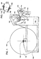
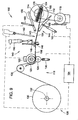
- FIGS. 1-14 show various structural and operational aspects of an exemplary embodiment of the invention in the form of a winding apparatus 100 for forming a filter element 102, as shown in FIG. 15 , including a filter pack 104, as shown in FIG. 16 , in the form of a coiled web 106 of fluted filter media 108.
- the winding apparatus 100 of the exemplary embodiment performs a number of functions in addition to simply winding the web 106 of fluted filter material onto the mandrel 112.
- the term winding apparatus is used herein to aid in the description of an apparatus and method according to the invention, and is not intended to be limiting with respect to practicing the invention.
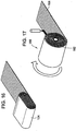
- the invention may be used for winding filter packs having non-circular cross sections, such as the race-track shaped filter pack 104 shown in FIG. 16 , or filter packs 110 having circular cross sections, as shown in FIG. 17 .
- the fluted filter media 108 used herein for describing the exemplary embodiment of the invention, includes a convoluted sheet 103 of porous filter material forming peaks 105 and valleys 107, attached to a face sheet 109 of porous filter material, with adjacent peaks 105 being regularly spaced from one another at a pitch 'P' of the web 106.
- the convoluted sheet 103 may be formed by any appropriate process, such as corrugating or pleating, but preferably by gathering, as described in a United States patent application, entitled “Gathered Filter Media and Method of Making Same,” bearing the US patent publication No. US 2006-0091066 assigned to the Assignee of the present invention.
- the winding apparatus 100 includes a mandrel 112, mounted for rotation about an axis 114 of the mandrel 112, a web feeder 116 for feeding the web 106 of fluted filter media 108 at a controlled linear speed, onto the mandrel 112, and a winding motor 118 operatively connected to the mandrel 112 for providing a controlled driving torque to the mandrel 112, to thereby maintain a controlled tension on the web 106 of fluted filter media as the web 106 is wound onto the mandrel 132.
- the winding motor 118 is an AC vector motor, operating in a torque mode.
- the web drive 116 includes cogged drive roller 120, having an outer periphery formed to engage the peaks and valleys 103, 105 of the web 106, driven by a web drive motor 122.
- the web drive 116 also includes a pinch roller 124, for holding the web 106 in engagement with the cogged drive roller 120, an idle roller 126 and a master roll support apparatus 128.
- the master roll support apparatus 128 of the exemplary embodiment is configured for mounting a large master roll 130 of the web 106 of filter media about a master roll axis 132, so that the web drive 116 can continuously feed the web 106 to the mandrel 112, along a feed direction 134 of the winding apparatus 100.
- the idle roller 126 is disposed between the master roll 130 and the cogged drive roller 120, in a position which causes the web 106 of fluted filter media to wrap partially around the periphery of the cogged drive roller 120 in a manner that helps to keep the peaks and valleys 103, 105 of the web 106 drivingly engaged with the cogged drive roller 120, so that the web drive motor 122 can drive the web 106 forward and backward along the feed path 134.
- the pinch roller 124 is mounted in such a way that a pinch roller actuator 136, in the form of a device such as a pneumatic or hydraulic cylinder, or an electric motor driven ball screw, for example, can move the pinch roller 124 out of engagement with the web 106 to facilitate feeding the web 106 past the cogged drive roller 120, when the web is being initially loaded into the winding apparatus 100.
- a pinch roller actuator 136 in the form of a device such as a pneumatic or hydraulic cylinder, or an electric motor driven ball screw, for example, can move the pinch roller 124 out of engagement with the web 106 to facilitate feeding the web 106 past the cogged drive roller 120, when the web is being initially loaded into the winding apparatus 100.
- the web drive motor 122 of the exemplary embodiment is an electric motor having an encoder that allows precise rotational positioning of the cogged drive roller 120, and the ability to precisely monitor the length of web 106 which has been fed in either direction along the feed path 134, toward or away from the mandrel 112.
- other types of motors or drive mechanisms allowing positioning and monitoring of length, may alternatively be used in practicing the invention.
- a web drive may differ considerably from the web drive 116 of the exemplary embodiment. It is further understood that, although the exemplary embodiment includes provisions for utilizing a large master roll 130 of the fluted filter media 108, to allow continuous feeding of the web 106, the invention may also be practiced, in other embodiments, with smaller master rolls, or with pre-cut lengths of the web 106.
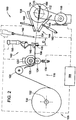
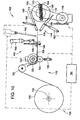
- the winding apparatus 100 of the exemplary embodiment also includes a cutter 140, an applicator 142, and a movable web guide apparatus 144, all disposed between the cogged drive wheel 122 and the mandrel 112.
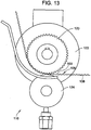
- the applicator 142 is used for applying a bead of adhesive/sealant 143 to the web 106, during winding of the coiled web 106, in a manner shown in FIGS. 5 and 6 , and described in more detail below.
- adhesive/sealant is intended to be inclusive rather than limiting, and includes any material that is applied through the applicator for purposes such as structurally bonding together the layers of a filter pack, according to the invention, or for providing a complete or partial seal against the flow of fluid through a filter pack according to the invention.
- the cutter 140 includes a pair of jaws 146, 148 operatively connected to be driven by a cutter actuator 150, for severing the web 106 a first and a second time to form leading and trailing edges respectively of the web 106.
- the jaws 146, 148 of the cutter 140 are disposed along the feed path 134 at a known distance from the web drive motor 122, so that the web drive motor 122 can position a first peak 105 of the web 106 under the cutter 140, in such a manner that the cutter 140 will sever the web through a first one of the peaks 105, to form the a leading edge 152 of the web 106, as shown in FIG.
- the web 106 may be severed a first time, on one of the peaks 105, and then the web drive motor 122 can feed out a length of web 106 that is equal to an integer multiple of the pitch P of the web 106, along the feed path 134 toward the mandrel 112, to position a second peak 105 directly under the cutter jaws 146, 148, so that the web 106 may be severed a second time, directly through the second peak 105, to form the trailing edge 154 of the web 106.
- the applicator 142 is preferably located between the cutter 140 and the mandrel 112 spaced an slightly beyond an over-travel distance 'D' from the cutter 140, to preclude fouling of the cutter 140 with adhesive/sealant dispensed by the applicator 142 during winding of the filter pack 104.
- the web drive motor 122 draws the web 106 back past the cutter 140 a distance equal to the over-travel distance D, prior to severing the web 106 the second time to form the trailing edge 154 of the web 106, so that the adhesive/sealant 143 on the web 106 extends virtually from the leading edge 152 to the trailing edge 154 of the coiled web 106.
- the flow of adhesive/sealant 143 through the applicator 142 is preferably stopped, or redirected to a different area of the web 106, so that the bead 143 of adhesive/sealant does not become excessive as the web 106 moves, first forward, and then backward, along the feed path 134.
- the web guide web guide 144 includes a pair of arms 156, 158 that are selectively rotated, by a pair of web guide actuators 160, 162, into and out of adjacency with the feed path 134, as described in greater detail below, at a point between the cutter 140 and the mandrel 112, for guiding the leading edge 152 and an adjacent initial length of the web 106 to the mandrel 112, after the first cut is made to sever the web 106, to form the leading edge 152, and after the open half-peak 111 at the leading edge 152 has been filled with adhesive/sealant 113.
- the mandrel 112 of the exemplary embodiment includes two side plates 166, 168 that are operatively connected to be driven in unison about the axis 114 of the mandrel.
- Aligned channels 170, 172 are attached to each of the side plates 166, 168 for receiving a portion of the opposing longitudinal edges of the web 106 adjacent the leading edge 152 to secure the leading edge 152 of the web 106 to the mandrel 112.
- the portion of the web 106 held by its longitudinal edges also forms an initial layer of media over which subsequent layers are wound to form a "coreless" race-track shaped filter pack 104, as shown in FIG. 16 .
- the exemplary embodiment includes two sets of web guide arms 156, 158, with one set operatively mounted respectively adjacent each of the side plates 166, 168.
- the winding apparatus 100 also includes a controller 164, operatively connected, as shown by dashed lines in FIGS. 1-10 , to the winder motor 118, the web drive motor 122, the cutter actuator 150, the pinch roller actuator 136, the applicator 142, and the actuators 160, 162 for the web guide arms 156, 158, for controlling the various component parts of the winding apparatus 100.
- the actuators 160, 162 may be provided in many forms, such as a pneumatic or hydraulic cylinder, or an electric motor driven ball screw.
- FIGS. 2-14 illustrating a sequence of operations related to forming a filter pack 104, having a non-circular cross-section.
- the web guide arms 156, 158 located in an open position, after loading the master roll 130 of fluted filter media into the master roll support apparatus 128, for rotation about the master roll axis, 132, the web 106 is fed over the idler roller 126, between the cogged roller 120 and the pinch roller 124 and through the cutter 140.
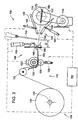
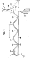
- the web 106 is jogged into a position where a first one of the peaks 105 is positioned under the cutter 140, to thereby initialize the positioning of the web 106, and the cutter 140 is actuated to sever the web 106 a first time through the first peak 105, as shown in FIGS. 3 and 11 , to form the leading edge 152 of the web 106.
- the web drive 126 advances a pre-wind length 115 of web 106 past the cutter 140, for application of an adhesive/sealant 113 in the half-peak 111 forming the leading edge 152 of the web 106.
- the adhesive/sealant 113 can be applied into the half-peak 111 by any known method, including having an operator of the winding apparatus 100 use a hand-held applicator to fill the half-peak 111 with an adhesive/sealant xmaterial such as a urethane material or a hot-melt glue.
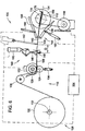
- the mandrel 112 is rotated to an initial position in which a channels 170, 172 of the mandrel 112 are generally aligned with the feed path 134, the web guide arms 156, 158 are moved to a closed position, and the web feeder 116 feeds an initial length of the web 106 through the web guide arms 156, 158, and into the channels 170, 172 in the mandrel 112.
- the channels 170, 172 of the mandrel 112 receive the leading edge 152 of the web and a portion of the longitudinal edges of the web 106, adjacent the leading edge 152.
- the applicator 142 applies a bead 143 of adhesive sealant to the upper face (as shown) of the web 106, at a point spaced far enough laterally inward from the longitudinal edge of the web 106, that the adhesive/sealant 143 will not spread into the channels 170, 172 in the mandrel 112 as the filter pack 104 is wound on the mandrel 112.
- the web guide arms 156, 158 are then moved to the open position, as shown in FIG. 6 , and the web drive motor 122 and winding motor 118 are energized to wind the filter pack 104, as shown in FIG. 7 .
- the web drive motor 122 feeds out a predetermined length of web 106, including an over-travel distance D, as shown in FIG. 7 .
- the web drive motor 122 is controlled during winding for feeding the web 106 of fluted filter media at a controlled linear speed onto the mandrel 112, and the winding motor 118 is controlled to provide a controlled driving torque to the mandrel 112, to thereby maintain a controlled tension on the web 106 of fluted filter media as the web 106 is wound onto the mandrel 112.
- the invention provides the capability to specifically tailor the speed at which the winding apparatus 100 operates to match the abilities of a particular individual operating the apparatus 100, while still maintaining a desired tension in the web 106.
- the linear speed at which the web 106 is fed to the mandrel 112, and the driving torque applied to the mandrel 112 can be continually controlled during the winding process, according to a predetermined program to precisely control tension applied to the web 106 at various points during winding of the filter pack 104. It may be desirable, for example, to have a pre-programmed acceleration and deceleration period at the beginning and end of the winding operation, where the linear speed at which the web 106 is fed to the mandrel 112 is respectively increased and decreased at predetermined rates.
- Either or both of the winding motor 118, or the controller 164 may include sensors or circuitry for sensing the driving torque of the winding motor 118.
- the driving torque to the mandrel 112 will preferably be maintained at a substantially constant value during winding, regardless of the linear speed at which the web 106 is being fed to the mandrel 112.
- the driving torque will cause the rotational speed of the mandrel 112 to vary, and allow the mandrel 112 to accelerate and decelerate, as required, to maintain a constant tension in the web 106 as the feed speed varies, as will inherently occur, for example, when winding a media pack with a non-circular cross section.
- the web 106 may simply be fed to the mandrel 112 at a substantially constant linear speed, during winding, and the winding motor 118 may be controlled to provide a substantially constant torque.
- substantially constant linear speed and torque are intended to mean that, except for brief periods of acceleration and deceleration at the beginning and end the winding operation, the linear speed will be held at a constant value, and the driving torque will be held at a constant values.
- the value of substantially constant linear speed for feeding the web 106 can be selected, and adjusted, to allow individual operators the flexibility to match the winding speed to their respective skill in operating the winding apparatus 100.
- substantially constant torque can be selected to provide a desired tension on the web 106 during winding, virtually independent of the skill of the operator, so that the coiled filter packs 104 will have a substantially uniform size and shape when completed, and to preclude crushing of the inner layers of the media 108 by excessive tension in the outer layers.
- the web drive motor 122 then reverses and draws the web back through the cutter 140 a distance equal to the over-travel distance D, and positions a second peak 105 of the web 106 directly under the cutter 140.
- the cutter 140 is actuated to sever the web 106 and form the trailing edge 154, as shown by dashed lines in FIG. 8 .
- FIG. 8 the web drive motor 122 then reverses and draws the web back through the cutter 140 a distance equal to the over-travel distance D, and positions a second peak 105 of the web 106 directly under the cutter 140.
- the cutter 140 is actuated to sever the web 106 and form the trailing edge 154, as shown by dashed lines in FIG. 8 .
- the operator then jogs the mandrel 112 to wrap the distal end of the web 106 onto the filter pack 104, fills the half-peak at the trailing edge 154 of the web 106 with an adhesive/sealant, and removes completed the filter pack 104 from the mandrel 112 by actuating a mechanism (not shown) that moves the plates 166-168 of the mandrel 112 apart from one another to release the filter pack 104 from the channels 170, 172 of the mandrel 112.
- the completed filter pack 104 is then set aside of the adhesive/sealant 143, 113 to cure, and/or is sent on to subsequent operations, such as attaching resilient seals 174, or other components, such as the seal support frame 176, that may be required to complete fabrication of the filter element 102 including the filter pack 104, as shown in FIG. 15 .
- the operations described above may then be repeated to form the next filter pack 104. It should be noted, however, that the operations described above in relation to FIG. 1 need not be performed for subsequent filter packs, because, once the winding apparatus 100 has been initialized to properly form the leading edge 152 of the first filter pack 104 to be formed from a given master roll 130 of media, the operations described in relation to FIG. 9 will simultaneously form the trailing edge 154 of one filter pack 104 and the leading edge 152 of the next filter pack 104, as shown in FIG. 11 .
- media packs 180 can also be used to form media packs 180, as shown in FIG. 17 , having the media 108 coiled around a central core. 182.
- the core may be attached to the mandrel 112, for rotation therewith, and the leading edge 152 of the web 106 is attached to the core, prior to beginning winding, through the use of a wide variety of means including, but not limited to, taping the leading edge to the core, sliding the leading edge into a slot in the core, bonding the leading edge to the core with an adhesive, or mechanically fastening the leading edge to the core with one or more fastening devices.
Landscapes
- Chemical & Material Sciences (AREA)
- Chemical Kinetics & Catalysis (AREA)
- Filtering Materials (AREA)
- Separation Using Semi-Permeable Membranes (AREA)
- Controlling Rewinding, Feeding, Winding, Or Abnormalities Of Webs (AREA)
- Winding Of Webs (AREA)
Applications Claiming Priority (2)
| Application Number | Priority Date | Filing Date | Title |
|---|---|---|---|
| US10/979,987 US7255300B2 (en) | 2004-11-03 | 2004-11-03 | Method and apparatus for winding a filter media pack |
| PCT/US2005/034366 WO2006052329A1 (en) | 2004-11-03 | 2005-09-22 | Method and apparatus for winding a filter media pack |
Publications (3)
| Publication Number | Publication Date |
|---|---|
| EP1807165A1 EP1807165A1 (en) | 2007-07-18 |
| EP1807165B1 EP1807165B1 (en) | 2010-11-24 |
| EP1807165B2 true EP1807165B2 (en) | 2018-08-08 |
Family
ID=35457062
Family Applications (1)
| Application Number | Title | Priority Date | Filing Date |
|---|---|---|---|
| EP05798742.2A Expired - Lifetime EP1807165B2 (en) | 2004-11-03 | 2005-09-22 | Method and apparatus for winding a filter media pack |
Country Status (9)
| Country | Link |
|---|---|
| US (1) | US7255300B2 (enExample) |
| EP (1) | EP1807165B2 (enExample) |
| JP (1) | JP4819820B2 (enExample) |
| AT (1) | ATE489154T1 (enExample) |
| AU (1) | AU2005305287B2 (enExample) |
| CA (1) | CA2585205C (enExample) |
| DE (1) | DE602005025003D1 (enExample) |
| MX (1) | MX2007005246A (enExample) |
| WO (1) | WO2006052329A1 (enExample) |
Families Citing this family (50)
| Publication number | Priority date | Publication date | Assignee | Title |
|---|---|---|---|---|
| US8226786B2 (en) | 2003-03-18 | 2012-07-24 | Donaldson Company, Inc. | Process and materials for coiling z-filter media, and/or closing flutes of filter media; and, products |
| US7396376B2 (en) | 2003-12-22 | 2008-07-08 | Donaldson Company, Inc. | Seal arrangement for filter element; filter element assembly; and, methods |
| US20090266041A1 (en) * | 2003-12-22 | 2009-10-29 | Donaldson Company, Inc. | Seal arrangement for filter element; Filter element assembly; and, methods |
| WO2007056589A2 (en) | 2005-11-09 | 2007-05-18 | Donaldson Company, Inc. | Seal arrangement for filter element; filter element assembly: and, methods |
| EP1748831B1 (en) | 2004-04-30 | 2012-06-13 | Donaldson Company, Inc. | Filter assemblies and method |
| US7905936B2 (en) | 2004-04-30 | 2011-03-15 | Donaldson Company, Inc. | Filter arrangements; housing; assemblies; and, methods |
| WO2006009766A1 (en) | 2004-06-18 | 2006-01-26 | Donaldson Company, Inc. | Air cleaner arrangements; serviceable filter cartridge; and, methods |
| DE602005019417D1 (de) | 2004-07-20 | 2010-04-01 | Donaldson Co Inc | Z-filtermedienpackungsanordnung, filterpatrone, luftreinigungsvorrichtungsanordnung und verfahren |
| US20070186528A1 (en) * | 2006-02-15 | 2007-08-16 | Baldwin Filters, Inc. | Fluted filter apparatus |
| US20110197556A1 (en) | 2004-11-02 | 2011-08-18 | Baldwin Filters, Inc. | Filter element |
| US7318851B2 (en) | 2004-11-02 | 2008-01-15 | Baldwin Filters, Inc. | Filter element |
| US7931725B2 (en) | 2004-11-02 | 2011-04-26 | Baldwin Filters, Inc. | Fluted filter apparatus |
| US7909954B2 (en) * | 2004-11-03 | 2011-03-22 | Baldwin Filters, Inc. | Method and apparatus for winding a filter media pack |
| US7569090B2 (en) * | 2004-11-12 | 2009-08-04 | Donaldson Company, Inc. | Method of forming filter arrangements; and, apparatus |
| WO2007044677A1 (en) | 2005-10-11 | 2007-04-19 | Donaldson Company, Inc. | Air filter arrangement; assembly; and, methods |
| DE102006001126A1 (de) | 2006-01-09 | 2007-07-12 | Kettenbach Gmbh & Co. Kg | Dentalabformmassen, daraus hergestellte gehärtete Produkte und Verwendung von Tensiden zur Herstellung von Dentalabformmassen |
| EP1986761A2 (en) | 2006-01-20 | 2008-11-05 | Donaldson Company, Inc. | Air cleaner configured for receipt of various sized filter cartridges; components thereof; and, methods |
| US7753982B2 (en) | 2006-02-17 | 2010-07-13 | Baldwin Filters, Inc. | Filter with drained jacket, seal indicator/lock means, and seal baffle |
| US7713321B2 (en) | 2006-06-22 | 2010-05-11 | Donaldson Company, Inc. | Air cleaner arrangements; components thereof; and, methods |
| WO2007149561A2 (en) | 2006-06-22 | 2007-12-27 | Donaldson Company, Inc. | Air cleaner arrangements; components thereof; and, methods |
| US10040020B2 (en) * | 2006-12-06 | 2018-08-07 | Baldwin Filters, Inc. | Fluid filter apparatus having filter media wound about a winding frame |
| US9757676B2 (en) | 2006-12-06 | 2017-09-12 | Baldwin Filters, Inc. | Method and apparatus for winding a filter element |
| US7744739B1 (en) | 2006-12-20 | 2010-06-29 | Clarcor Inc. | Spiral-wound cylindrical electrostatic oil cleaner |
| US8728193B2 (en) | 2007-09-07 | 2014-05-20 | Donaldson Company, Inc. | Air filter assembly; components thereof and methods |
| US9545593B2 (en) | 2007-11-01 | 2017-01-17 | Baldwin Filters, Inc. | Winding core pressure relief for fluted filter |
| US7959703B2 (en) | 2008-06-30 | 2011-06-14 | Baldwin Filters, Inc. | Fluted filter with integrated frame |
| US8048187B2 (en) | 2008-06-30 | 2011-11-01 | Baldwin Filters, Inc. | Filter frame attachment and fluted filter having same |
| US8197687B2 (en) * | 2008-08-19 | 2012-06-12 | Perry Equipment Corporation | Contaminant adsorbent fluted filter element |
| IT1391420B1 (it) * | 2008-09-24 | 2011-12-23 | Perini Fabio Spa | "macchina ribobinatrice e metodo di avvolgimento" |
| WO2010045644A1 (en) | 2008-10-17 | 2010-04-22 | Bioair Solutions, Llc | Filtration media for filtration/purification of a liquid or gas, related reactor modules, filtration devices and methods |
| US8506668B2 (en) | 2009-03-30 | 2013-08-13 | Baldwin Filters, Inc. | Fluted filter with axial seal |
| US9174160B2 (en) * | 2009-08-19 | 2015-11-03 | Baldwin Filters, Inc. | Collapsible core, filter, and method |
| WO2011115979A2 (en) | 2010-03-17 | 2011-09-22 | Baldwin Filters, Inc. | Fluid filter |
| WO2011115973A2 (en) | 2010-03-17 | 2011-09-22 | Baldwin Filters, Inc. | Fluid filter |
| DE102012013470A1 (de) * | 2012-07-09 | 2014-05-08 | Mann + Hummel Gmbh | Verfahren und Vorrichtung zum Fertigen von Filterelementen sowie Filterelement |
| WO2014018528A1 (en) | 2012-07-25 | 2014-01-30 | Baldwin Filters, Inc. | Filter housing, fluted filter and safety filter |
| CN103939439B (zh) * | 2013-01-18 | 2016-01-20 | 东莞市海莎过滤器有限公司 | 一种自动贴边机 |
| MY178267A (en) * | 2013-03-15 | 2020-10-07 | Scorrboard Llc | Establishing a registered score, slit or slot in corrugated board, and articles produced therefrom |
| US11420417B2 (en) | 2013-03-15 | 2022-08-23 | Scorrboard Llc | Methods and apparatus for producing scored mediums, and articles and compositions resulting therefrom |
| TW201444759A (zh) * | 2013-05-24 | 2014-12-01 | Sheng Qi Machinery Co Ltd | Pe濾芯之捲收裝置 |
| KR101519796B1 (ko) * | 2014-07-24 | 2015-05-12 | 김순자 | 오일필터용 코어 제조장치 |
| EP4628190A3 (en) | 2014-10-10 | 2025-12-10 | Baldwin Filters, Inc. | Filter media and filter element with adhesive reinforcing |
| TWI534006B (zh) * | 2015-04-09 | 2016-05-21 | Filter element and its forming method | |
| US10682597B2 (en) | 2016-04-14 | 2020-06-16 | Baldwin Filters, Inc. | Filter system |
| US10800133B2 (en) | 2016-04-20 | 2020-10-13 | Scorrboard, Llc | System and method for producing a facing for a board product with strategically placed scores |
| US10328654B2 (en) | 2016-04-20 | 2019-06-25 | Scorrboard, Llc | System and method for producing a multi-layered board having a medium with improved structure |
| US11027513B2 (en) | 2016-04-20 | 2021-06-08 | Scorrboard Llc | System and method for producing an articulating board product having a facing with score lines in register to fluting |
| US11027515B2 (en) | 2016-04-20 | 2021-06-08 | Scorrboard Llc | System and method for producing multi-layered board having at least three mediums with at least two mediums being different |
| WO2020185505A1 (en) | 2019-03-08 | 2020-09-17 | Parker-Hannifin Corporation | Air filter with improved handle |
| CN116194186B (zh) | 2020-10-06 | 2026-03-31 | 安美世滤清系统公司 | 具有独特形状的过滤器组件 |
Citations (2)
| Publication number | Priority date | Publication date | Assignee | Title |
|---|---|---|---|---|
| US6179890B1 (en) † | 1999-02-26 | 2001-01-30 | Donaldson Company, Inc. | Air cleaner having sealing arrangement between media arrangement and housing |
| US6416605B1 (en) † | 1999-11-24 | 2002-07-09 | Donaldson Company, Inc. | Method for manufacturing fluted media |
Family Cites Families (52)
| Publication number | Priority date | Publication date | Assignee | Title |
|---|---|---|---|---|
| US3025963A (en) | 1958-03-13 | 1962-03-20 | Russell H Curtis | Products useful as filtering devices and methods of making them |
| SE302235B (enExample) | 1966-02-08 | 1968-07-08 | Svenska Flaektfabriken Ab | |
| US4253228A (en) | 1978-09-14 | 1981-03-03 | Filterspun, Inc. | Apparatus and system for forming wound filters |
| JPS57102221A (en) * | 1980-12-16 | 1982-06-25 | Toshimi Kuma | Production of element for deodorization |
| DE3280289D1 (de) | 1981-02-23 | 1991-02-14 | Nippon Denso Co | Filterelement fuer fluidumreinigungssysteme. |
| US4410427A (en) | 1981-11-02 | 1983-10-18 | Donaldson Company, Inc. | Fluid filtering device |
| GB8329395D0 (en) | 1983-11-03 | 1983-12-07 | Ciba Geigy Ag | Photopolymerisable compositions |
| JPS60112320A (ja) | 1983-11-24 | 1985-06-18 | Hitachi Ltd | トライステ−トゲ−トの保護方式 |
| JPS60244318A (ja) * | 1984-05-18 | 1985-12-04 | Seibu Giken:Kk | フイルタ−素子およびその製造法 |
| JPS60193217U (ja) * | 1984-05-31 | 1985-12-23 | 株式会社 土屋製作所 | ハニカム型フイルタエレメント |
| US4720292B1 (en) | 1986-07-14 | 1991-09-10 | Cylindrical air filter with lightweight housing and radially directed seal | |
| JPS63122617A (ja) | 1986-11-13 | 1988-05-26 | Lion Corp | 皮膚洗浄剤 |
| JPH0231131A (ja) | 1988-07-20 | 1990-02-01 | Rigaku Keisoku Kk | 石炭の工業分析方法および赤外線加熱炉 |
| JPH0745073B2 (ja) * | 1989-08-14 | 1995-05-17 | 新日本製鐵株式会社 | 金属箔の巻取方法および装置 |
| US5238474A (en) | 1990-10-19 | 1993-08-24 | Donaldson Company, Inc. | Filtration arrangement |
| US5245897A (en) | 1991-11-25 | 1993-09-21 | E. I. Du Pont De Nemours And Company | System and method for advancing the leading edge of a corrugated web |
| ATE141891T1 (de) * | 1992-03-04 | 1996-09-15 | Ciba Geigy Ag | Verfahren und vorrichtung zum aufwickeln von wickelfähigen substraten |
| JP3239517B2 (ja) | 1992-06-17 | 2001-12-17 | 株式会社デンソー | 濾過エレメントの製造方法 |
| JPH06106013A (ja) * | 1992-09-28 | 1994-04-19 | Sanyo Electric Co Ltd | エアフィルタ |
| JP3316916B2 (ja) * | 1993-03-18 | 2002-08-19 | トヨタ自動車株式会社 | 金属板の巻取り方法 |
| US5484466A (en) | 1994-02-14 | 1996-01-16 | Baldwin Filters, Inc. | Air filter element with radial seal sealing gasket |
| JPH08257361A (ja) * | 1995-03-24 | 1996-10-08 | Nippon Steel Corp | ハニカム体の巻回方法 |
| JP3578429B2 (ja) * | 1996-04-16 | 2004-10-20 | 新日本製鐵株式会社 | 金属ハニカム体の巻取方法 |
| US5820646A (en) | 1996-04-26 | 1998-10-13 | Donaldson Company, Inc. | Inline filter apparatus |
| US5902364A (en) | 1996-04-26 | 1999-05-11 | Donaldson Company, Inc. | Conical filter |
| US5792247A (en) | 1996-04-26 | 1998-08-11 | Donaldson Company, Inc. | Integrated resonator and filter apparatus |
| US5895574A (en) | 1996-04-26 | 1999-04-20 | Donaldson Company, Inc. | Rolled liquid filter using fluted media |
| DE19704147A1 (de) * | 1997-02-04 | 1998-08-06 | Emitec Emissionstechnologie | Hitzebeständiger und regenerierbarer Filterkörper mit Strömungswegen |
| ATE220657T1 (de) | 1998-11-04 | 2002-08-15 | Rohm & Haas | Verfahren zum herstellen mit grosser ausbeute von methylmethacrylat oder methacrylsäure |
| JP4463994B2 (ja) | 1999-02-26 | 2010-05-19 | ドナルドソン カンパニー,インコーポレイティド | フィルタ構成、密封システム、および方法 |
| US6235195B1 (en) | 1999-02-26 | 2001-05-22 | Donaldson Company, Inc. | Filter element incorporating a handle member |
| US6190432B1 (en) | 1999-02-26 | 2001-02-20 | Donaldson Company, Inc. | Filter arrangement; sealing system; and methods |
| US6221122B1 (en) | 1999-02-26 | 2001-04-24 | Donaldson Company, Inc. | Filter element and methods |
| US6348084B1 (en) | 1999-11-05 | 2002-02-19 | Donaldson Company, Inc. | Filter element, air cleaner, and methods |
| US6348085B1 (en) | 1999-11-10 | 2002-02-19 | Donaldson Company, Inc. | Filter arrangement and methods |
| US6776814B2 (en) * | 2000-03-09 | 2004-08-17 | Fleetguard, Inc. | Dual section exhaust aftertreatment filter and method |
| JP2001269516A (ja) * | 2000-03-28 | 2001-10-02 | Ishizu Seisakusho Co Ltd | 筒形フィルターの製造方法及びその装置 |
| US6368374B1 (en) | 2000-06-13 | 2002-04-09 | Donaldson Company, Inc. | Filter arrangement and methods |
| US6673136B2 (en) | 2000-09-05 | 2004-01-06 | Donaldson Company, Inc. | Air filtration arrangements having fluted media constructions and methods |
| US6743317B2 (en) | 2000-12-19 | 2004-06-01 | Robert M. Wydeven | Method of sealing, housing and constructing honeycomb filters |
| US6447567B1 (en) | 2001-05-14 | 2002-09-10 | Baldwin Filters, Inc. | Air filter element with integral radial seal gasket |
| US6610126B2 (en) | 2001-06-06 | 2003-08-26 | Donaldson Company, Inc. | Filter element having sealing members and methods |
| US6517598B2 (en) | 2001-06-06 | 2003-02-11 | Donaldson Company, Inc. | Filter element having flange and methods |
| DE10152552A1 (de) | 2001-10-24 | 2003-05-08 | Mann & Hummel Filter | Filterelement, insbesondere für die Filtrierung von Flüssigkeiten |
| JP4388375B2 (ja) | 2001-12-03 | 2009-12-24 | ドナルドソン カンパニー,インコーポレイティド | 波形の媒体シートを使用するフィルタエレメント |
| US6966940B2 (en) | 2002-04-04 | 2005-11-22 | Donaldson Company, Inc. | Air filter cartridge |
| DE10227050B3 (de) | 2002-06-17 | 2004-01-29 | Albert Frey Verpackungsentwicklungen Und Vertriebs-Gmbh | Wellpappe mit Aufreißlinie |
| US6887343B2 (en) | 2002-12-20 | 2005-05-03 | Fleetguard, Inc. | Filter coating, winding, finishing and manufacturing system |
| US20060091061A1 (en) | 2004-11-02 | 2006-05-04 | Baldwin Filters, Inc. | Filter assembly with sealing system |
| US20060091084A1 (en) | 2004-11-02 | 2006-05-04 | Baldwin Filters, Inc. | Fluted filter media with intermediate flow restriction and method of making same |
| US20060091064A1 (en) | 2004-11-02 | 2006-05-04 | Baldwin Filters, Inc. | Filter apparatus with separable seal support frame |
| US8042694B2 (en) | 2004-11-02 | 2011-10-25 | Baldwin Filters, Inc. | Gathered filter media for an air filter and method of making same |
-
2004
- 2004-11-03 US US10/979,987 patent/US7255300B2/en not_active Expired - Lifetime
-
2005
- 2005-09-22 JP JP2007538924A patent/JP4819820B2/ja not_active Expired - Lifetime
- 2005-09-22 EP EP05798742.2A patent/EP1807165B2/en not_active Expired - Lifetime
- 2005-09-22 AU AU2005305287A patent/AU2005305287B2/en not_active Expired
- 2005-09-22 MX MX2007005246A patent/MX2007005246A/es active IP Right Grant
- 2005-09-22 CA CA2585205A patent/CA2585205C/en not_active Expired - Lifetime
- 2005-09-22 DE DE602005025003T patent/DE602005025003D1/de not_active Expired - Lifetime
- 2005-09-22 WO PCT/US2005/034366 patent/WO2006052329A1/en not_active Ceased
- 2005-09-22 AT AT05798742T patent/ATE489154T1/de not_active IP Right Cessation
Patent Citations (2)
| Publication number | Priority date | Publication date | Assignee | Title |
|---|---|---|---|---|
| US6179890B1 (en) † | 1999-02-26 | 2001-01-30 | Donaldson Company, Inc. | Air cleaner having sealing arrangement between media arrangement and housing |
| US6416605B1 (en) † | 1999-11-24 | 2002-07-09 | Donaldson Company, Inc. | Method for manufacturing fluted media |
Also Published As
| Publication number | Publication date |
|---|---|
| ATE489154T1 (de) | 2010-12-15 |
| CA2585205A1 (en) | 2006-05-18 |
| AU2005305287A1 (en) | 2006-05-18 |
| US7255300B2 (en) | 2007-08-14 |
| MX2007005246A (es) | 2007-07-09 |
| DE602005025003D1 (de) | 2011-01-05 |
| CA2585205C (en) | 2011-03-29 |
| JP4819820B2 (ja) | 2011-11-24 |
| EP1807165B1 (en) | 2010-11-24 |
| US20060151655A1 (en) | 2006-07-13 |
| JP2008518756A (ja) | 2008-06-05 |
| AU2005305287B2 (en) | 2010-11-25 |
| EP1807165A1 (en) | 2007-07-18 |
| WO2006052329A1 (en) | 2006-05-18 |
Similar Documents
| Publication | Publication Date | Title |
|---|---|---|
| EP1807165B2 (en) | Method and apparatus for winding a filter media pack | |
| US7909954B2 (en) | Method and apparatus for winding a filter media pack | |
| JP2008518756A5 (enExample) | ||
| US8545658B2 (en) | Apparatus and methods for forming filter sleeves having circumferential pleats for use in a bag-type filter assembly | |
| EP1631425B1 (en) | Machine for producing tubular products with a cutter carried by a rotating arm | |
| US5322230A (en) | Method and apparatus for preparing a replacement paper roll for flying roll change, particularly to supply paper to a rotary printing press | |
| CN1732120A (zh) | 具有对所形成卷的最终边缘涂胶的涂胶装置的复绕机以及相对卷绕方法 | |
| CN115703602A (zh) | 用于电能存储装置的生产的卷绕材料条的设备和相关方法 | |
| CN109153215B (zh) | 用于生产瓦楞板的系统 | |
| CN100374361C (zh) | 用于制造沾污物清除带带卷的设备和沾污物清除带带卷的制造方法 | |
| JP5632678B2 (ja) | 潰せる芯、フィルタ、および方法 | |
| CA1251674A (en) | Apparatus and method for wrapping an external tape support about a filter element assembly | |
| JP7547475B2 (ja) | 貼付機ユニット、タイヤ製造デバイス、およびストリップをドラムに貼り付けるための方法 | |
| EP1757550A2 (en) | Backing film wind-up in a fiber placement machine | |
| US7243475B1 (en) | Bagger or bag dispenser with reversible take-up reel and method | |
| EP1799553B1 (en) | Bander apparatus and method of using same | |
| CN117142203B (zh) | 一种自动收卷系统以及自动收卷方法 | |
| JPH1159015A5 (enExample) | ||
| US20040265526A1 (en) | Spiral wound tubes, method and apparatus for forming the same | |
| JP4328280B2 (ja) | 原反フィルムおよびその収納蓄積方法 | |
| JP2003024722A (ja) | エアフィルタ用ろ材の製造装置 | |
| JPH04118214U (ja) | 帯状材の巻取具 |
Legal Events
| Date | Code | Title | Description |
|---|---|---|---|
| PUAI | Public reference made under article 153(3) epc to a published international application that has entered the european phase |
Free format text: ORIGINAL CODE: 0009012 |
|
| 17P | Request for examination filed |
Effective date: 20070509 |
|
| AK | Designated contracting states |
Kind code of ref document: A1 Designated state(s): AT BE BG CH CY CZ DE DK EE ES FI FR GB GR HU IE IS IT LI LT LU LV MC NL PL PT RO SE SI SK TR |
|
| DAX | Request for extension of the european patent (deleted) | ||
| 17Q | First examination report despatched |
Effective date: 20090915 |
|
| GRAP | Despatch of communication of intention to grant a patent |
Free format text: ORIGINAL CODE: EPIDOSNIGR1 |
|
| GRAS | Grant fee paid |
Free format text: ORIGINAL CODE: EPIDOSNIGR3 |
|
| GRAA | (expected) grant |
Free format text: ORIGINAL CODE: 0009210 |
|
| AK | Designated contracting states |
Kind code of ref document: B1 Designated state(s): AT BE BG CH CY CZ DE DK EE ES FI FR GB GR HU IE IS IT LI LT LU LV MC NL PL PT RO SE SI SK TR |
|
| REG | Reference to a national code |
Ref country code: GB Ref legal event code: FG4D |
|
| REG | Reference to a national code |
Ref country code: CH Ref legal event code: EP |
|
| REG | Reference to a national code |
Ref country code: IE Ref legal event code: FG4D |
|
| REF | Corresponds to: |
Ref document number: 602005025003 Country of ref document: DE Date of ref document: 20110105 Kind code of ref document: P |
|
| REG | Reference to a national code |
Ref country code: NL Ref legal event code: VDEP Effective date: 20101124 |
|
| LTIE | Lt: invalidation of european patent or patent extension |
Effective date: 20101124 |
|
| PG25 | Lapsed in a contracting state [announced via postgrant information from national office to epo] |
Ref country code: LT Free format text: LAPSE BECAUSE OF FAILURE TO SUBMIT A TRANSLATION OF THE DESCRIPTION OR TO PAY THE FEE WITHIN THE PRESCRIBED TIME-LIMIT Effective date: 20101124 |
|
| PG25 | Lapsed in a contracting state [announced via postgrant information from national office to epo] |
Ref country code: SE Free format text: LAPSE BECAUSE OF FAILURE TO SUBMIT A TRANSLATION OF THE DESCRIPTION OR TO PAY THE FEE WITHIN THE PRESCRIBED TIME-LIMIT Effective date: 20101124 Ref country code: AT Free format text: LAPSE BECAUSE OF FAILURE TO SUBMIT A TRANSLATION OF THE DESCRIPTION OR TO PAY THE FEE WITHIN THE PRESCRIBED TIME-LIMIT Effective date: 20101124 Ref country code: IS Free format text: LAPSE BECAUSE OF FAILURE TO SUBMIT A TRANSLATION OF THE DESCRIPTION OR TO PAY THE FEE WITHIN THE PRESCRIBED TIME-LIMIT Effective date: 20110324 Ref country code: SI Free format text: LAPSE BECAUSE OF FAILURE TO SUBMIT A TRANSLATION OF THE DESCRIPTION OR TO PAY THE FEE WITHIN THE PRESCRIBED TIME-LIMIT Effective date: 20101124 Ref country code: PT Free format text: LAPSE BECAUSE OF FAILURE TO SUBMIT A TRANSLATION OF THE DESCRIPTION OR TO PAY THE FEE WITHIN THE PRESCRIBED TIME-LIMIT Effective date: 20110324 Ref country code: CY Free format text: LAPSE BECAUSE OF FAILURE TO SUBMIT A TRANSLATION OF THE DESCRIPTION OR TO PAY THE FEE WITHIN THE PRESCRIBED TIME-LIMIT Effective date: 20101124 Ref country code: FI Free format text: LAPSE BECAUSE OF FAILURE TO SUBMIT A TRANSLATION OF THE DESCRIPTION OR TO PAY THE FEE WITHIN THE PRESCRIBED TIME-LIMIT Effective date: 20101124 Ref country code: BG Free format text: LAPSE BECAUSE OF FAILURE TO SUBMIT A TRANSLATION OF THE DESCRIPTION OR TO PAY THE FEE WITHIN THE PRESCRIBED TIME-LIMIT Effective date: 20110224 Ref country code: NL Free format text: LAPSE BECAUSE OF FAILURE TO SUBMIT A TRANSLATION OF THE DESCRIPTION OR TO PAY THE FEE WITHIN THE PRESCRIBED TIME-LIMIT Effective date: 20101124 Ref country code: LV Free format text: LAPSE BECAUSE OF FAILURE TO SUBMIT A TRANSLATION OF THE DESCRIPTION OR TO PAY THE FEE WITHIN THE PRESCRIBED TIME-LIMIT Effective date: 20101124 |
|
| PG25 | Lapsed in a contracting state [announced via postgrant information from national office to epo] |
Ref country code: GR Free format text: LAPSE BECAUSE OF FAILURE TO SUBMIT A TRANSLATION OF THE DESCRIPTION OR TO PAY THE FEE WITHIN THE PRESCRIBED TIME-LIMIT Effective date: 20110225 |
|
| PG25 | Lapsed in a contracting state [announced via postgrant information from national office to epo] |
Ref country code: EE Free format text: LAPSE BECAUSE OF FAILURE TO SUBMIT A TRANSLATION OF THE DESCRIPTION OR TO PAY THE FEE WITHIN THE PRESCRIBED TIME-LIMIT Effective date: 20101124 Ref country code: BE Free format text: LAPSE BECAUSE OF FAILURE TO SUBMIT A TRANSLATION OF THE DESCRIPTION OR TO PAY THE FEE WITHIN THE PRESCRIBED TIME-LIMIT Effective date: 20101124 Ref country code: CZ Free format text: LAPSE BECAUSE OF FAILURE TO SUBMIT A TRANSLATION OF THE DESCRIPTION OR TO PAY THE FEE WITHIN THE PRESCRIBED TIME-LIMIT Effective date: 20101124 Ref country code: ES Free format text: LAPSE BECAUSE OF FAILURE TO SUBMIT A TRANSLATION OF THE DESCRIPTION OR TO PAY THE FEE WITHIN THE PRESCRIBED TIME-LIMIT Effective date: 20110307 |
|
| PLBI | Opposition filed |
Free format text: ORIGINAL CODE: 0009260 |
|
| PG25 | Lapsed in a contracting state [announced via postgrant information from national office to epo] |
Ref country code: RO Free format text: LAPSE BECAUSE OF FAILURE TO SUBMIT A TRANSLATION OF THE DESCRIPTION OR TO PAY THE FEE WITHIN THE PRESCRIBED TIME-LIMIT Effective date: 20101124 Ref country code: PL Free format text: LAPSE BECAUSE OF FAILURE TO SUBMIT A TRANSLATION OF THE DESCRIPTION OR TO PAY THE FEE WITHIN THE PRESCRIBED TIME-LIMIT Effective date: 20101124 Ref country code: DK Free format text: LAPSE BECAUSE OF FAILURE TO SUBMIT A TRANSLATION OF THE DESCRIPTION OR TO PAY THE FEE WITHIN THE PRESCRIBED TIME-LIMIT Effective date: 20101124 Ref country code: SK Free format text: LAPSE BECAUSE OF FAILURE TO SUBMIT A TRANSLATION OF THE DESCRIPTION OR TO PAY THE FEE WITHIN THE PRESCRIBED TIME-LIMIT Effective date: 20101124 |
|
| PLAX | Notice of opposition and request to file observation + time limit sent |
Free format text: ORIGINAL CODE: EPIDOSNOBS2 |
|
| 26 | Opposition filed |
Opponent name: DONALDSON COMPANY, INC. Effective date: 20110824 |
|
| REG | Reference to a national code |
Ref country code: DE Ref legal event code: R026 Ref document number: 602005025003 Country of ref document: DE Effective date: 20110824 |
|
| PG25 | Lapsed in a contracting state [announced via postgrant information from national office to epo] |
Ref country code: IT Free format text: LAPSE BECAUSE OF FAILURE TO SUBMIT A TRANSLATION OF THE DESCRIPTION OR TO PAY THE FEE WITHIN THE PRESCRIBED TIME-LIMIT Effective date: 20101124 |
|
| PLAF | Information modified related to communication of a notice of opposition and request to file observations + time limit |
Free format text: ORIGINAL CODE: EPIDOSCOBS2 |
|
| PLBB | Reply of patent proprietor to notice(s) of opposition received |
Free format text: ORIGINAL CODE: EPIDOSNOBS3 |
|
| PG25 | Lapsed in a contracting state [announced via postgrant information from national office to epo] |
Ref country code: MC Free format text: LAPSE BECAUSE OF NON-PAYMENT OF DUE FEES Effective date: 20110930 |
|
| REG | Reference to a national code |
Ref country code: CH Ref legal event code: PL |
|
| REG | Reference to a national code |
Ref country code: IE Ref legal event code: MM4A |
|
| REG | Reference to a national code |
Ref country code: FR Ref legal event code: ST Effective date: 20120531 |
|
| PLAB | Opposition data, opponent's data or that of the opponent's representative modified |
Free format text: ORIGINAL CODE: 0009299OPPO |
|
| PG25 | Lapsed in a contracting state [announced via postgrant information from national office to epo] |
Ref country code: LI Free format text: LAPSE BECAUSE OF NON-PAYMENT OF DUE FEES Effective date: 20110930 Ref country code: CH Free format text: LAPSE BECAUSE OF NON-PAYMENT OF DUE FEES Effective date: 20110930 Ref country code: IE Free format text: LAPSE BECAUSE OF NON-PAYMENT OF DUE FEES Effective date: 20110922 |
|
| R26 | Opposition filed (corrected) |
Opponent name: DONALDSON COMPANY, INC. Effective date: 20110824 |
|
| PG25 | Lapsed in a contracting state [announced via postgrant information from national office to epo] |
Ref country code: FR Free format text: LAPSE BECAUSE OF NON-PAYMENT OF DUE FEES Effective date: 20110930 |
|
| PG25 | Lapsed in a contracting state [announced via postgrant information from national office to epo] |
Ref country code: LU Free format text: LAPSE BECAUSE OF NON-PAYMENT OF DUE FEES Effective date: 20110922 |
|
| APAH | Appeal reference modified |
Free format text: ORIGINAL CODE: EPIDOSCREFNO |
|
| APBM | Appeal reference recorded |
Free format text: ORIGINAL CODE: EPIDOSNREFNO |
|
| APBP | Date of receipt of notice of appeal recorded |
Free format text: ORIGINAL CODE: EPIDOSNNOA2O |
|
| APBM | Appeal reference recorded |
Free format text: ORIGINAL CODE: EPIDOSNREFNO |
|
| APBP | Date of receipt of notice of appeal recorded |
Free format text: ORIGINAL CODE: EPIDOSNNOA2O |
|
| PG25 | Lapsed in a contracting state [announced via postgrant information from national office to epo] |
Ref country code: TR Free format text: LAPSE BECAUSE OF FAILURE TO SUBMIT A TRANSLATION OF THE DESCRIPTION OR TO PAY THE FEE WITHIN THE PRESCRIBED TIME-LIMIT Effective date: 20101124 |
|
| APBQ | Date of receipt of statement of grounds of appeal recorded |
Free format text: ORIGINAL CODE: EPIDOSNNOA3O |
|
| PG25 | Lapsed in a contracting state [announced via postgrant information from national office to epo] |
Ref country code: HU Free format text: LAPSE BECAUSE OF FAILURE TO SUBMIT A TRANSLATION OF THE DESCRIPTION OR TO PAY THE FEE WITHIN THE PRESCRIBED TIME-LIMIT Effective date: 20101124 |
|
| REG | Reference to a national code |
Ref country code: DE Ref legal event code: R082 Ref document number: 602005025003 Country of ref document: DE Representative=s name: HOEGER, STELLRECHT & PARTNER PATENTANWAELTE MB, DE |
|
| APBU | Appeal procedure closed |
Free format text: ORIGINAL CODE: EPIDOSNNOA9O |
|
| PUAH | Patent maintained in amended form |
Free format text: ORIGINAL CODE: 0009272 |
|
| STAA | Information on the status of an ep patent application or granted ep patent |
Free format text: STATUS: PATENT MAINTAINED AS AMENDED |
|
| 27A | Patent maintained in amended form |
Effective date: 20180808 |
|
| AK | Designated contracting states |
Kind code of ref document: B2 Designated state(s): AT BE BG CH CY CZ DE DK EE ES FI FR GB GR HU IE IS IT LI LT LU LV MC NL PL PT RO SE SI SK TR |
|
| REG | Reference to a national code |
Ref country code: DE Ref legal event code: R102 Ref document number: 602005025003 Country of ref document: DE |
|
| REG | Reference to a national code |
Ref country code: DE Ref legal event code: R082 Ref document number: 602005025003 Country of ref document: DE Representative=s name: HOEGER, STELLRECHT & PARTNER PATENTANWAELTE MB, DE |
|
| P01 | Opt-out of the competence of the unified patent court (upc) registered |
Effective date: 20230524 |
|
| PGFP | Annual fee paid to national office [announced via postgrant information from national office to epo] |
Ref country code: DE Payment date: 20240927 Year of fee payment: 20 |
|
| PGFP | Annual fee paid to national office [announced via postgrant information from national office to epo] |
Ref country code: GB Payment date: 20240927 Year of fee payment: 20 |
|
| REG | Reference to a national code |
Ref country code: DE Ref legal event code: R071 Ref document number: 602005025003 Country of ref document: DE |
|
| REG | Reference to a national code |
Ref country code: GB Ref legal event code: PE20 Expiry date: 20250921 |