EP1806803B1 - Assemblies for electrochemical devices - Google Patents
Assemblies for electrochemical devices Download PDFInfo
- Publication number
- EP1806803B1 EP1806803B1 EP06026267.2A EP06026267A EP1806803B1 EP 1806803 B1 EP1806803 B1 EP 1806803B1 EP 06026267 A EP06026267 A EP 06026267A EP 1806803 B1 EP1806803 B1 EP 1806803B1
- Authority
- EP
- European Patent Office
- Prior art keywords
- membrane
- assemblies according
- subgasket
- mea
- layers
- Prior art date
- Legal status (The legal status is an assumption and is not a legal conclusion. Google has not performed a legal analysis and makes no representation as to the accuracy of the status listed.)
- Active
Links
- 230000000712 assembly Effects 0.000 title claims description 34
- 238000000429 assembly Methods 0.000 title claims description 34
- 239000012528 membrane Substances 0.000 claims description 129
- 210000004379 membrane Anatomy 0.000 claims description 128
- 229920000554 ionomer Polymers 0.000 claims description 52
- 239000007789 gas Substances 0.000 claims description 33
- 239000000446 fuel Substances 0.000 claims description 25
- 239000000178 monomer Substances 0.000 claims description 19
- 239000012809 cooling fluid Substances 0.000 claims description 18
- 229910006095 SO2F Inorganic materials 0.000 claims description 16
- 239000000203 mixture Substances 0.000 claims description 16
- 229910006069 SO3H Inorganic materials 0.000 claims description 13
- 239000002253 acid Substances 0.000 claims description 13
- 239000003054 catalyst Substances 0.000 claims description 13
- BFKJFAAPBSQJPD-UHFFFAOYSA-N tetrafluoroethene Chemical group FC(F)=C(F)F BFKJFAAPBSQJPD-UHFFFAOYSA-N 0.000 claims description 12
- OKTJSMMVPCPJKN-UHFFFAOYSA-N Carbon Chemical compound [C] OKTJSMMVPCPJKN-UHFFFAOYSA-N 0.000 claims description 11
- 229910052739 hydrogen Inorganic materials 0.000 claims description 11
- 229910052751 metal Inorganic materials 0.000 claims description 10
- 239000002184 metal Substances 0.000 claims description 10
- -1 sulphonyl groups Chemical group 0.000 claims description 10
- 229910052740 iodine Inorganic materials 0.000 claims description 8
- 229920000642 polymer Polymers 0.000 claims description 8
- 125000003709 fluoroalkyl group Chemical group 0.000 claims description 6
- 125000003178 carboxy group Chemical group [H]OC(*)=O 0.000 claims description 5
- 229910052801 chlorine Inorganic materials 0.000 claims description 5
- 229910052731 fluorine Inorganic materials 0.000 claims description 5
- 230000007062 hydrolysis Effects 0.000 claims description 5
- 238000006460 hydrolysis reaction Methods 0.000 claims description 5
- 239000002243 precursor Substances 0.000 claims description 5
- 125000002023 trifluoromethyl group Chemical group FC(F)(F)* 0.000 claims description 5
- UUAGAQFQZIEFAH-UHFFFAOYSA-N chlorotrifluoroethylene Chemical group FC(F)=C(F)Cl UUAGAQFQZIEFAH-UHFFFAOYSA-N 0.000 claims description 4
- 150000003839 salts Chemical class 0.000 claims description 4
- 125000006527 (C1-C5) alkyl group Chemical group 0.000 claims description 2
- AYCANDRGVPTASA-UHFFFAOYSA-N 1-bromo-1,2,2-trifluoroethene Chemical group FC(F)=C(F)Br AYCANDRGVPTASA-UHFFFAOYSA-N 0.000 claims description 2
- KRHYYFGTRYWZRS-UHFFFAOYSA-M Fluoride anion Chemical compound [F-] KRHYYFGTRYWZRS-UHFFFAOYSA-M 0.000 claims description 2
- 125000004429 atom Chemical group 0.000 claims description 2
- 229910052794 bromium Inorganic materials 0.000 claims description 2
- 125000004122 cyclic group Chemical group 0.000 claims description 2
- 125000001033 ether group Chemical group 0.000 claims description 2
- 229920001519 homopolymer Polymers 0.000 claims description 2
- 150000002739 metals Chemical class 0.000 claims description 2
- 229910052750 molybdenum Inorganic materials 0.000 claims description 2
- 125000004430 oxygen atom Chemical group O* 0.000 claims description 2
- 229920003936 perfluorinated ionomer Polymers 0.000 claims description 2
- 229910052703 rhodium Inorganic materials 0.000 claims description 2
- 229910052707 ruthenium Inorganic materials 0.000 claims description 2
- 229920001169 thermoplastic Polymers 0.000 claims description 2
- 239000004416 thermosoftening plastic Substances 0.000 claims description 2
- 125000006340 pentafluoro ethyl group Chemical group FC(F)(F)C(F)(F)* 0.000 claims 1
- 230000009466 transformation Effects 0.000 claims 1
- 241000539716 Mea Species 0.000 description 66
- 238000000034 method Methods 0.000 description 25
- 238000009792 diffusion process Methods 0.000 description 23
- XLYOFNOQVPJJNP-UHFFFAOYSA-N water Substances O XLYOFNOQVPJJNP-UHFFFAOYSA-N 0.000 description 19
- 238000007731 hot pressing Methods 0.000 description 17
- 230000003197 catalytic effect Effects 0.000 description 14
- 239000004810 polytetrafluoroethylene Substances 0.000 description 11
- 229920001343 polytetrafluoroethylene Polymers 0.000 description 11
- 230000000052 comparative effect Effects 0.000 description 10
- 238000001816 cooling Methods 0.000 description 10
- 238000002360 preparation method Methods 0.000 description 10
- OKKJLVBELUTLKV-UHFFFAOYSA-N Methanol Chemical compound OC OKKJLVBELUTLKV-UHFFFAOYSA-N 0.000 description 9
- 239000003795 chemical substances by application Substances 0.000 description 9
- 238000006116 polymerization reaction Methods 0.000 description 8
- ZCYVEMRRCGMTRW-UHFFFAOYSA-N 7553-56-2 Chemical compound [I] ZCYVEMRRCGMTRW-UHFFFAOYSA-N 0.000 description 7
- 238000004132 cross linking Methods 0.000 description 7
- BASFCYQUMIYNBI-UHFFFAOYSA-N platinum Substances [Pt] BASFCYQUMIYNBI-UHFFFAOYSA-N 0.000 description 7
- 238000006243 chemical reaction Methods 0.000 description 6
- 239000000460 chlorine Substances 0.000 description 6
- 229920001577 copolymer Polymers 0.000 description 6
- 239000011630 iodine Substances 0.000 description 6
- 229910052799 carbon Inorganic materials 0.000 description 5
- 239000001257 hydrogen Substances 0.000 description 5
- 150000002500 ions Chemical class 0.000 description 5
- 150000002978 peroxides Chemical class 0.000 description 5
- 239000000243 solution Substances 0.000 description 5
- 239000004831 Hot glue Substances 0.000 description 4
- 125000001246 bromo group Chemical group Br* 0.000 description 4
- 239000003792 electrolyte Substances 0.000 description 4
- 238000002474 experimental method Methods 0.000 description 4
- 239000012530 fluid Substances 0.000 description 4
- 229920001973 fluoroelastomer Polymers 0.000 description 4
- 125000004435 hydrogen atom Chemical class [H]* 0.000 description 4
- 230000002209 hydrophobic effect Effects 0.000 description 4
- 229910052700 potassium Inorganic materials 0.000 description 4
- 239000004094 surface-active agent Substances 0.000 description 4
- 238000012546 transfer Methods 0.000 description 4
- XEKOWRVHYACXOJ-UHFFFAOYSA-N Ethyl acetate Chemical compound CCOC(C)=O XEKOWRVHYACXOJ-UHFFFAOYSA-N 0.000 description 3
- UFHFLCQGNIYNRP-UHFFFAOYSA-N Hydrogen Chemical compound [H][H] UFHFLCQGNIYNRP-UHFFFAOYSA-N 0.000 description 3
- ZLMJMSJWJFRBEC-UHFFFAOYSA-N Potassium Chemical compound [K] ZLMJMSJWJFRBEC-UHFFFAOYSA-N 0.000 description 3
- 239000007864 aqueous solution Substances 0.000 description 3
- 125000004432 carbon atom Chemical group C* 0.000 description 3
- 239000006185 dispersion Substances 0.000 description 3
- 239000000839 emulsion Substances 0.000 description 3
- HDERJYVLTPVNRI-UHFFFAOYSA-N ethene;ethenyl acetate Chemical compound C=C.CC(=O)OC=C HDERJYVLTPVNRI-UHFFFAOYSA-N 0.000 description 3
- 229920002313 fluoropolymer Polymers 0.000 description 3
- 238000010438 heat treatment Methods 0.000 description 3
- HCDGVLDPFQMKDK-UHFFFAOYSA-N hexafluoropropylene Chemical compound FC(F)=C(F)C(F)(F)F HCDGVLDPFQMKDK-UHFFFAOYSA-N 0.000 description 3
- 239000003014 ion exchange membrane Substances 0.000 description 3
- 239000011591 potassium Substances 0.000 description 3
- KOMNUTZXSVSERR-UHFFFAOYSA-N 1,3,5-tris(prop-2-enyl)-1,3,5-triazinane-2,4,6-trione Chemical compound C=CCN1C(=O)N(CC=C)C(=O)N(CC=C)C1=O KOMNUTZXSVSERR-UHFFFAOYSA-N 0.000 description 2
- QGZKDVFQNNGYKY-UHFFFAOYSA-N Ammonia Chemical compound N QGZKDVFQNNGYKY-UHFFFAOYSA-N 0.000 description 2
- 229920000049 Carbon (fiber) Polymers 0.000 description 2
- LFQSCWFLJHTTHZ-UHFFFAOYSA-N Ethanol Chemical compound CCO LFQSCWFLJHTTHZ-UHFFFAOYSA-N 0.000 description 2
- NPYPAHLBTDXSSS-UHFFFAOYSA-N Potassium ion Chemical compound [K+] NPYPAHLBTDXSSS-UHFFFAOYSA-N 0.000 description 2
- 229910052784 alkaline earth metal Inorganic materials 0.000 description 2
- 150000001342 alkaline earth metals Chemical class 0.000 description 2
- 125000003118 aryl group Chemical group 0.000 description 2
- 238000009835 boiling Methods 0.000 description 2
- 150000001649 bromium compounds Chemical class 0.000 description 2
- 229910052791 calcium Inorganic materials 0.000 description 2
- 239000004917 carbon fiber Substances 0.000 description 2
- 150000001768 cations Chemical class 0.000 description 2
- 239000011248 coating agent Substances 0.000 description 2
- 238000000576 coating method Methods 0.000 description 2
- 150000001875 compounds Chemical class 0.000 description 2
- 239000003431 cross linking reagent Substances 0.000 description 2
- 239000008367 deionised water Substances 0.000 description 2
- 229910021641 deionized water Inorganic materials 0.000 description 2
- 230000032798 delamination Effects 0.000 description 2
- 238000003487 electrochemical reaction Methods 0.000 description 2
- 238000007720 emulsion polymerization reaction Methods 0.000 description 2
- 239000004811 fluoropolymer Substances 0.000 description 2
- 125000000524 functional group Chemical group 0.000 description 2
- 239000003999 initiator Substances 0.000 description 2
- 229910052745 lead Inorganic materials 0.000 description 2
- 150000002736 metal compounds Chemical class 0.000 description 2
- 238000012703 microemulsion polymerization Methods 0.000 description 2
- 230000020477 pH reduction Effects 0.000 description 2
- 229910052697 platinum Inorganic materials 0.000 description 2
- 229910001414 potassium ion Inorganic materials 0.000 description 2
- 230000001681 protective effect Effects 0.000 description 2
- 239000011541 reaction mixture Substances 0.000 description 2
- 239000007787 solid Substances 0.000 description 2
- 239000002904 solvent Substances 0.000 description 2
- 239000000126 substance Substances 0.000 description 2
- 125000000020 sulfo group Chemical group O=S(=O)([*])O[H] 0.000 description 2
- 238000012360 testing method Methods 0.000 description 2
- 210000001519 tissue Anatomy 0.000 description 2
- 125000000876 trifluoromethoxy group Chemical group FC(F)(F)O* 0.000 description 2
- 125000006273 (C1-C3) alkyl group Chemical group 0.000 description 1
- BJELTSYBAHKXRW-UHFFFAOYSA-N 2,4,6-triallyloxy-1,3,5-triazine Chemical compound C=CCOC1=NC(OCC=C)=NC(OCC=C)=N1 BJELTSYBAHKXRW-UHFFFAOYSA-N 0.000 description 1
- XMNIXWIUMCBBBL-UHFFFAOYSA-N 2-(2-phenylpropan-2-ylperoxy)propan-2-ylbenzene Chemical compound C=1C=CC=CC=1C(C)(C)OOC(C)(C)C1=CC=CC=C1 XMNIXWIUMCBBBL-UHFFFAOYSA-N 0.000 description 1
- ZHZPKMZKYBQGKG-UHFFFAOYSA-N 6-methyl-2,4,6-tris(trifluoromethyl)oxane-2,4-diol Chemical compound FC(F)(F)C1(C)CC(O)(C(F)(F)F)CC(O)(C(F)(F)F)O1 ZHZPKMZKYBQGKG-UHFFFAOYSA-N 0.000 description 1
- QGZKDVFQNNGYKY-UHFFFAOYSA-O Ammonium Chemical compound [NH4+] QGZKDVFQNNGYKY-UHFFFAOYSA-O 0.000 description 1
- OMPJBNCRMGITSC-UHFFFAOYSA-N Benzoylperoxide Chemical compound C=1C=CC=CC=1C(=O)OOC(=O)C1=CC=CC=C1 OMPJBNCRMGITSC-UHFFFAOYSA-N 0.000 description 1
- 229920002799 BoPET Polymers 0.000 description 1
- KZBUYRJDOAKODT-UHFFFAOYSA-N Chlorine Chemical compound ClCl KZBUYRJDOAKODT-UHFFFAOYSA-N 0.000 description 1
- MYMOFIZGZYHOMD-UHFFFAOYSA-N Dioxygen Chemical compound O=O MYMOFIZGZYHOMD-UHFFFAOYSA-N 0.000 description 1
- 229920001780 ECTFE Polymers 0.000 description 1
- 229920002943 EPDM rubber Polymers 0.000 description 1
- OTMSDBZUPAUEDD-UHFFFAOYSA-N Ethane Chemical compound CC OTMSDBZUPAUEDD-UHFFFAOYSA-N 0.000 description 1
- 229920002449 FKM Polymers 0.000 description 1
- CWYNVVGOOAEACU-UHFFFAOYSA-N Fe2+ Chemical compound [Fe+2] CWYNVVGOOAEACU-UHFFFAOYSA-N 0.000 description 1
- 239000013032 Hydrocarbon resin Substances 0.000 description 1
- KWYHDKDOAIKMQN-UHFFFAOYSA-N N,N,N',N'-tetramethylethylenediamine Chemical compound CN(C)CCN(C)C KWYHDKDOAIKMQN-UHFFFAOYSA-N 0.000 description 1
- 229920000557 Nafion® Polymers 0.000 description 1
- 239000002033 PVDF binder Substances 0.000 description 1
- 229920006169 Perfluoroelastomer Polymers 0.000 description 1
- 239000004952 Polyamide Substances 0.000 description 1
- RAHZWNYVWXNFOC-UHFFFAOYSA-N Sulphur dioxide Chemical group O=S=O RAHZWNYVWXNFOC-UHFFFAOYSA-N 0.000 description 1
- 239000007983 Tris buffer Substances 0.000 description 1
- QYKIQEUNHZKYBP-UHFFFAOYSA-N Vinyl ether Chemical class C=COC=C QYKIQEUNHZKYBP-UHFFFAOYSA-N 0.000 description 1
- NIXOWILDQLNWCW-UHFFFAOYSA-N acrylic acid group Chemical group C(C=C)(=O)O NIXOWILDQLNWCW-UHFFFAOYSA-N 0.000 description 1
- 239000000654 additive Substances 0.000 description 1
- 150000001298 alcohols Chemical class 0.000 description 1
- 125000001931 aliphatic group Chemical group 0.000 description 1
- 150000001336 alkenes Chemical class 0.000 description 1
- 239000003963 antioxidant agent Substances 0.000 description 1
- 230000003078 antioxidant effect Effects 0.000 description 1
- 235000006708 antioxidants Nutrition 0.000 description 1
- 150000001558 benzoic acid derivatives Chemical class 0.000 description 1
- 235000019400 benzoyl peroxide Nutrition 0.000 description 1
- 230000015572 biosynthetic process Effects 0.000 description 1
- DFFDSQBEGQFJJU-UHFFFAOYSA-M butyl carbonate Chemical compound CCCCOC([O-])=O DFFDSQBEGQFJJU-UHFFFAOYSA-M 0.000 description 1
- 238000003490 calendering Methods 0.000 description 1
- 150000004649 carbonic acid derivatives Chemical class 0.000 description 1
- 238000005266 casting Methods 0.000 description 1
- 125000001309 chloro group Chemical group Cl* 0.000 description 1
- 230000015271 coagulation Effects 0.000 description 1
- 238000005345 coagulation Methods 0.000 description 1
- 238000002485 combustion reaction Methods 0.000 description 1
- 238000007796 conventional method Methods 0.000 description 1
- 230000008034 disappearance Effects 0.000 description 1
- 238000009826 distribution Methods 0.000 description 1
- 229920001971 elastomer Polymers 0.000 description 1
- 239000000806 elastomer Substances 0.000 description 1
- 239000010411 electrocatalyst Substances 0.000 description 1
- 229920000840 ethylene tetrafluoroethylene copolymer Polymers 0.000 description 1
- 238000011156 evaluation Methods 0.000 description 1
- 238000001125 extrusion Methods 0.000 description 1
- 239000000945 filler Substances 0.000 description 1
- 239000012467 final product Substances 0.000 description 1
- 125000001153 fluoro group Chemical group F* 0.000 description 1
- 238000009432 framing Methods 0.000 description 1
- 238000007710 freezing Methods 0.000 description 1
- 230000008014 freezing Effects 0.000 description 1
- 239000008246 gaseous mixture Substances 0.000 description 1
- 239000003292 glue Substances 0.000 description 1
- 150000002334 glycols Chemical class 0.000 description 1
- 125000005842 heteroatom Chemical group 0.000 description 1
- VLKZOEOYAKHREP-UHFFFAOYSA-N hexane Substances CCCCCC VLKZOEOYAKHREP-UHFFFAOYSA-N 0.000 description 1
- 229930195733 hydrocarbon Natural products 0.000 description 1
- 229920006270 hydrocarbon resin Polymers 0.000 description 1
- 150000002430 hydrocarbons Chemical class 0.000 description 1
- XMBWDFGMSWQBCA-UHFFFAOYSA-N hydrogen iodide Chemical compound I XMBWDFGMSWQBCA-UHFFFAOYSA-N 0.000 description 1
- 150000004679 hydroxides Chemical class 0.000 description 1
- 125000002887 hydroxy group Chemical group [H]O* 0.000 description 1
- 238000005470 impregnation Methods 0.000 description 1
- 238000001746 injection moulding Methods 0.000 description 1
- 150000004694 iodide salts Chemical class 0.000 description 1
- 239000003273 ketjen black Substances 0.000 description 1
- 230000002045 lasting effect Effects 0.000 description 1
- 239000007788 liquid Substances 0.000 description 1
- 230000002101 lytic effect Effects 0.000 description 1
- 229920002521 macromolecule Polymers 0.000 description 1
- 229910052749 magnesium Inorganic materials 0.000 description 1
- 238000012423 maintenance Methods 0.000 description 1
- 238000004519 manufacturing process Methods 0.000 description 1
- 239000000463 material Substances 0.000 description 1
- 229910000000 metal hydroxide Inorganic materials 0.000 description 1
- 229910044991 metal oxide Inorganic materials 0.000 description 1
- 150000004706 metal oxides Chemical class 0.000 description 1
- 238000002156 mixing Methods 0.000 description 1
- 125000000896 monocarboxylic acid group Chemical group 0.000 description 1
- BLYOHBPLFYXHQA-UHFFFAOYSA-N n,n-bis(prop-2-enyl)prop-2-enamide Chemical compound C=CCN(CC=C)C(=O)C=C BLYOHBPLFYXHQA-UHFFFAOYSA-N 0.000 description 1
- DYUWTXWIYMHBQS-UHFFFAOYSA-N n-prop-2-enylprop-2-en-1-amine Chemical compound C=CCNCC=C DYUWTXWIYMHBQS-UHFFFAOYSA-N 0.000 description 1
- JRZJOMJEPLMPRA-UHFFFAOYSA-N olefin Natural products CCCCCCCC=C JRZJOMJEPLMPRA-UHFFFAOYSA-N 0.000 description 1
- 150000003891 oxalate salts Chemical class 0.000 description 1
- 239000002245 particle Substances 0.000 description 1
- 125000005010 perfluoroalkyl group Chemical group 0.000 description 1
- 239000010702 perfluoropolyether Substances 0.000 description 1
- AQSJGOWTSHOLKH-UHFFFAOYSA-N phosphite(3-) Chemical class [O-]P([O-])[O-] AQSJGOWTSHOLKH-UHFFFAOYSA-N 0.000 description 1
- 239000000049 pigment Substances 0.000 description 1
- 229920002493 poly(chlorotrifluoroethylene) Polymers 0.000 description 1
- 229920002647 polyamide Polymers 0.000 description 1
- 239000005023 polychlorotrifluoroethylene (PCTFE) polymer Substances 0.000 description 1
- 239000005518 polymer electrolyte Substances 0.000 description 1
- 239000003505 polymerization initiator Substances 0.000 description 1
- 229920001296 polysiloxane Polymers 0.000 description 1
- 229920002981 polyvinylidene fluoride Polymers 0.000 description 1
- 239000000843 powder Substances 0.000 description 1
- 239000000047 product Substances 0.000 description 1
- 230000002035 prolonged effect Effects 0.000 description 1
- 238000000746 purification Methods 0.000 description 1
- 238000010526 radical polymerization reaction Methods 0.000 description 1
- 239000012429 reaction media Substances 0.000 description 1
- 239000012763 reinforcing filler Substances 0.000 description 1
- 239000012812 sealant material Substances 0.000 description 1
- 229920002379 silicone rubber Polymers 0.000 description 1
- CHQMHPLRPQMAMX-UHFFFAOYSA-L sodium persulfate Chemical compound [Na+].[Na+].[O-]S(=O)(=O)OOS([O-])(=O)=O CHQMHPLRPQMAMX-UHFFFAOYSA-L 0.000 description 1
- 239000007784 solid electrolyte Substances 0.000 description 1
- 239000003381 stabilizer Substances 0.000 description 1
- 238000003756 stirring Methods 0.000 description 1
- 239000000725 suspension Substances 0.000 description 1
- 229920002725 thermoplastic elastomer Polymers 0.000 description 1
- 239000012815 thermoplastic material Substances 0.000 description 1
- 239000002562 thickening agent Substances 0.000 description 1
- 150000003918 triazines Chemical class 0.000 description 1
- KJWHEZXBZQXVSA-UHFFFAOYSA-N tris(prop-2-enyl) phosphite Chemical compound C=CCOP(OCC=C)OCC=C KJWHEZXBZQXVSA-UHFFFAOYSA-N 0.000 description 1
- 238000005406 washing Methods 0.000 description 1
- 229910052725 zinc Inorganic materials 0.000 description 1
- XOOUIPVCVHRTMJ-UHFFFAOYSA-L zinc stearate Chemical class [Zn+2].CCCCCCCCCCCCCCCCCC([O-])=O.CCCCCCCCCCCCCCCCCC([O-])=O XOOUIPVCVHRTMJ-UHFFFAOYSA-L 0.000 description 1
Images


Classifications
-
- H—ELECTRICITY
- H01—ELECTRIC ELEMENTS
- H01M—PROCESSES OR MEANS, e.g. BATTERIES, FOR THE DIRECT CONVERSION OF CHEMICAL ENERGY INTO ELECTRICAL ENERGY
- H01M4/00—Electrodes
- H01M4/86—Inert electrodes with catalytic activity, e.g. for fuel cells
-
- H—ELECTRICITY
- H01—ELECTRIC ELEMENTS
- H01M—PROCESSES OR MEANS, e.g. BATTERIES, FOR THE DIRECT CONVERSION OF CHEMICAL ENERGY INTO ELECTRICAL ENERGY
- H01M8/00—Fuel cells; Manufacture thereof
- H01M8/02—Details
- H01M8/0271—Sealing or supporting means around electrodes, matrices or membranes
-
- H—ELECTRICITY
- H01—ELECTRIC ELEMENTS
- H01M—PROCESSES OR MEANS, e.g. BATTERIES, FOR THE DIRECT CONVERSION OF CHEMICAL ENERGY INTO ELECTRICAL ENERGY
- H01M4/00—Electrodes
- H01M4/86—Inert electrodes with catalytic activity, e.g. for fuel cells
- H01M4/90—Selection of catalytic material
- H01M4/92—Metals of platinum group
- H01M4/921—Alloys or mixtures with metallic elements
-
- H—ELECTRICITY
- H01—ELECTRIC ELEMENTS
- H01M—PROCESSES OR MEANS, e.g. BATTERIES, FOR THE DIRECT CONVERSION OF CHEMICAL ENERGY INTO ELECTRICAL ENERGY
- H01M4/00—Electrodes
- H01M4/86—Inert electrodes with catalytic activity, e.g. for fuel cells
- H01M4/90—Selection of catalytic material
- H01M4/92—Metals of platinum group
- H01M4/925—Metals of platinum group supported on carriers, e.g. powder carriers
- H01M4/926—Metals of platinum group supported on carriers, e.g. powder carriers on carbon or graphite
-
- H—ELECTRICITY
- H01—ELECTRIC ELEMENTS
- H01M—PROCESSES OR MEANS, e.g. BATTERIES, FOR THE DIRECT CONVERSION OF CHEMICAL ENERGY INTO ELECTRICAL ENERGY
- H01M8/00—Fuel cells; Manufacture thereof
- H01M8/02—Details
- H01M8/0271—Sealing or supporting means around electrodes, matrices or membranes
- H01M8/0273—Sealing or supporting means around electrodes, matrices or membranes with sealing or supporting means in the form of a frame
-
- H—ELECTRICITY
- H01—ELECTRIC ELEMENTS
- H01M—PROCESSES OR MEANS, e.g. BATTERIES, FOR THE DIRECT CONVERSION OF CHEMICAL ENERGY INTO ELECTRICAL ENERGY
- H01M8/00—Fuel cells; Manufacture thereof
- H01M8/02—Details
- H01M8/0271—Sealing or supporting means around electrodes, matrices or membranes
- H01M8/0276—Sealing means characterised by their form
-
- H—ELECTRICITY
- H01—ELECTRIC ELEMENTS
- H01M—PROCESSES OR MEANS, e.g. BATTERIES, FOR THE DIRECT CONVERSION OF CHEMICAL ENERGY INTO ELECTRICAL ENERGY
- H01M8/00—Fuel cells; Manufacture thereof
- H01M8/10—Fuel cells with solid electrolytes
- H01M8/1004—Fuel cells with solid electrolytes characterised by membrane-electrode assemblies [MEA]
-
- H—ELECTRICITY
- H01—ELECTRIC ELEMENTS
- H01M—PROCESSES OR MEANS, e.g. BATTERIES, FOR THE DIRECT CONVERSION OF CHEMICAL ENERGY INTO ELECTRICAL ENERGY
- H01M8/00—Fuel cells; Manufacture thereof
- H01M8/10—Fuel cells with solid electrolytes
- H01M8/1016—Fuel cells with solid electrolytes characterised by the electrolyte material
- H01M8/1018—Polymeric electrolyte materials
- H01M8/102—Polymeric electrolyte materials characterised by the chemical structure of the main chain of the ion-conducting polymer
- H01M8/1023—Polymeric electrolyte materials characterised by the chemical structure of the main chain of the ion-conducting polymer having only carbon, e.g. polyarylenes, polystyrenes or polybutadiene-styrenes
-
- H—ELECTRICITY
- H01—ELECTRIC ELEMENTS
- H01M—PROCESSES OR MEANS, e.g. BATTERIES, FOR THE DIRECT CONVERSION OF CHEMICAL ENERGY INTO ELECTRICAL ENERGY
- H01M8/00—Fuel cells; Manufacture thereof
- H01M8/10—Fuel cells with solid electrolytes
- H01M8/1016—Fuel cells with solid electrolytes characterised by the electrolyte material
- H01M8/1018—Polymeric electrolyte materials
- H01M8/1039—Polymeric electrolyte materials halogenated, e.g. sulfonated polyvinylidene fluorides
-
- H—ELECTRICITY
- H01—ELECTRIC ELEMENTS
- H01M—PROCESSES OR MEANS, e.g. BATTERIES, FOR THE DIRECT CONVERSION OF CHEMICAL ENERGY INTO ELECTRICAL ENERGY
- H01M8/00—Fuel cells; Manufacture thereof
- H01M8/10—Fuel cells with solid electrolytes
- H01M8/1016—Fuel cells with solid electrolytes characterised by the electrolyte material
- H01M8/1018—Polymeric electrolyte materials
- H01M8/1067—Polymeric electrolyte materials characterised by their physical properties, e.g. porosity, ionic conductivity or thickness
-
- H—ELECTRICITY
- H01—ELECTRIC ELEMENTS
- H01M—PROCESSES OR MEANS, e.g. BATTERIES, FOR THE DIRECT CONVERSION OF CHEMICAL ENERGY INTO ELECTRICAL ENERGY
- H01M8/00—Fuel cells; Manufacture thereof
- H01M8/10—Fuel cells with solid electrolytes
- H01M2008/1095—Fuel cells with polymeric electrolytes
-
- Y—GENERAL TAGGING OF NEW TECHNOLOGICAL DEVELOPMENTS; GENERAL TAGGING OF CROSS-SECTIONAL TECHNOLOGIES SPANNING OVER SEVERAL SECTIONS OF THE IPC; TECHNICAL SUBJECTS COVERED BY FORMER USPC CROSS-REFERENCE ART COLLECTIONS [XRACs] AND DIGESTS
- Y02—TECHNOLOGIES OR APPLICATIONS FOR MITIGATION OR ADAPTATION AGAINST CLIMATE CHANGE
- Y02E—REDUCTION OF GREENHOUSE GAS [GHG] EMISSIONS, RELATED TO ENERGY GENERATION, TRANSMISSION OR DISTRIBUTION
- Y02E60/00—Enabling technologies; Technologies with a potential or indirect contribution to GHG emissions mitigation
- Y02E60/30—Hydrogen technology
- Y02E60/50—Fuel cells
-
- Y—GENERAL TAGGING OF NEW TECHNOLOGICAL DEVELOPMENTS; GENERAL TAGGING OF CROSS-SECTIONAL TECHNOLOGIES SPANNING OVER SEVERAL SECTIONS OF THE IPC; TECHNICAL SUBJECTS COVERED BY FORMER USPC CROSS-REFERENCE ART COLLECTIONS [XRACs] AND DIGESTS
- Y02—TECHNOLOGIES OR APPLICATIONS FOR MITIGATION OR ADAPTATION AGAINST CLIMATE CHANGE
- Y02P—CLIMATE CHANGE MITIGATION TECHNOLOGIES IN THE PRODUCTION OR PROCESSING OF GOODS
- Y02P70/00—Climate change mitigation technologies in the production process for final industrial or consumer products
- Y02P70/50—Manufacturing or production processes characterised by the final manufactured product
Definitions
- the present invention relates to eletrode membrane assemblies to be used in electrochemical devices, in particular in PEM fuel cells (polymeric electrolyte fuel cells), and their process.
- the PEM fuel cells comprise a core comprising an ionomeric membrane having on each side an electrode containing the catalyst for the combustion reaction, on each side of the membrane at least one gas diffusion layer is first placed, followed by a bipolar plate.
- the comburent is generally air or pure oxygen; the fuel is for example pure hydrogen, gaseous mixtures containing hydrogen, or methanol or ethanol aqueous solutions.
- the two sections form a reaction cell.
- the key feature of a fuel cell is the Membrane Electrode Assembly or MEA placed, as said, between the bipolar plates of the reaction cell.
- the simplest membrane electrode assembly is formed of an ionomeric membrane, acting as electrolyte, with an electrocatalytic layer (catalyzed area) applied on both sides of the membrane.
- CCM Catalyst Coated Membrane
- MEA 3-layer MEA
- MEAs are used in electrochemical devices with at least one gas diffusion layer in contact with each electrocatalytic layer.
- the 5-layer MEA is an assembly wherein, on each of the two electrocatalytic layers of a 3-layer MEA as defined above, a gas microdiffusion layer is applied.
- the latter has hydro- phobic characteristics, generally is a mixture of carbon powder and PTFE.
- the 7-layer MEA is an assembly wherein on each of the two microdiffusion layers of the 5-layer MEA a gas macrodiffusion layer is applied. The latter has hydrophobic characteristics, generally formed of PTFE-treated carbon fibers or tissues.
- the single reaction cells are assembled in electrical series thus obtaining a device called fuel cell stack.
- the fuel cell stacks supply powers, generally between some tenths of watt and some hundreds of Kilowatt and generates heat. A cooling system is therefore necessary to remove the heat produced by the electrochemical reaction. In the stacks it is a common practice to alternate the single reaction cells with cooling cells fed with a fluid, generally demineralized water.
- EP 1399983 discloses a membrane electrode assembly comprising a membrane, two electrocatalyst layers that have a lower area than the membrane and a subgasket on the two sides of the membrane, wherein the edges of the membrane are enclosed among said subgaskets.
- US 6716549 pertains to a fuel cell with comprising a MEA and gas diffusion layers, wherein the ion-exchange membrane into the MEA has no openings and no subgaskets.
- US 2002/004159 pertains to a solid polymer electrolyte fuel cell having a structure comprising a gas diffusion electrode provided on both surfaces of an ion exchange membrane, said membrane having no openings and being not enclosed among subgaskets.
- US6716550 discloses a MEA comprising a ion exchange membrane having two electrodes disposed on its surfaces; an optional integral seal comprising a fluid impermeable sealant materials that is impregnated along the edge of the MEA; and a framing seal that engages the edge of the MEA.
- US 6610435 discloses a MEA wherein a gasket completely covers the entire periphery of the solid electrolyte membrane, so that gas leakage and electrode deformations are prevented.
- EP 1167400 discloses fluorinated ionomers with sulphonic groups that can be used in the preparation of membrane and electrocatalytic layers for use in MEAs.
- the portion of the ionomeric membrane surface coated by the electrocatalytic layer represents a fraction generally between 40 and 90% of the total membrane surface. This surface fraction is indicated as “active area” as it is involved in the electrochemical reaction.
- a protective film can be applied, generally formed of an inert material towards the reaction taking place in the electro- chemical device.
- the protective film is generally known as "subgasket” and has the purpose to improve the MEA handling, for example to facilitate the assembling in electrochemical devices and to protect the polymeric electrolyte from the contact with the bipolar plates.
- the obtained device is called MEA with subgasket.
- FIG. 1 A 3-layer MEA with subgasket according to the prior art is illustrated in Fig. 1 in a plan view.
- (1') indicates the central area (in dark) which represents the active area as above,
- (2') is the membrane surface coated by the subgasket.
- (6') indicates the three openings, respect- ively, in the upper- and in the lower-part of the MEA. When the latter is assembled in a stack, the openings form 6 distribution channels, which in couples are used, respectively, for the comburent and fuel transport and for the cooling fluid.
- Fig. 2 reports a MEA sectional view along B-B of Fig. 1 (4') represents the ionomeric membrane, the two layers (3'), positioned symmetrically with respect to the membrane, indicate the subgaskets, the two layers (5') correspond to the catalytic layers, which coat the membrane in correspondence with the active area.
- Fig. 3 reports a MEA sectional view along A-A of Fig. 1 , wherein (4') represents the ionomeric membrane, the two layers (3'), positioned symmetrically with respect to the membrane, correspond to the subgaskets.
- Figg. 2 and 3 show that the subgaskets cover the non active portion of each side of the membrane.
- these electrochemical devices maintain a high efficiency for long time by using cooling fluids having a high purity degree, in order for avoiding pollution sources.
- cooling fluid deionized water is used.
- Deionized water of the quality required for the working of polymeric membrane electrochemical devices, has to be produced by a plant for the purification of water.
- the cooling fluid amount required for the working of a fuel cell stack is quite large. Therefore, from an industrial point of view, the use of high purity cooling fluids in electrochemical devices represents an additional cost for the plant and its maintenance.
- An object of the present invention is an assembly or MEA device comprising a membrane, said membrane comprising openings for the comburent, fuel and, cooling fluid transport , and, on each side, two electrocatalytic layers wherein:
- edges of the ionomeric membrane of the present invention are enclosed among the subgaskets and isolated both from the external environment and from the reaction and cooling fluids.
- the subgasket is applied in the non catalyzed area of the MEA, i.e. in the membrane area not coated by the catalyst.
- Two or more subgaskets can be present on one or both sides of the membrane.
- the MEA devices with subgaskets can be in form of 3-layer, 5-layer or 7-layer.
- Fig. 4 is a plan view of a 3-layer MEA device according to the present invention.
- the central area (1) represents the MEA active area.
- (2) represents the membrane surface coated with the subgasket. (1) together with (2) corresponds to the area of the ionomeric membrane.
- (3) represents the parts of the subgasket in mutual contact and which are not in contact with the membrane surface. (2) together with (3) corresponds to the subgasket area.
- (11) indicates the openings in the MEA for the comburent, fuel and cooling fluid transport, for example the tree upper openings represent the inlet of the above fluids, the lower openings the outlet of the above fluids.
- Fig. 5 is the section D-D of Fig. 4 .
- (4) represents the ionomeric membrane; (2) corresponds to the subgasket area coating the membrane and corresponds to (2) of Fig. 4 ; (3) corresponds to the overlapping area between the two subgaskets and corresponds to (3) of Fig. 4 .
- the two layers (5) represent the catalytic layers.
- Fig. 6 is the section C-C of Fig. 4 .
- the membrane is represented by (4).
- (2) represents the subgaskets coating the membrane;
- (3) corresponds to the overlapping area between the two subgaskets.
- Threfore a 3-layer MEA according to the present invention comprises:
- the 5-layer MEA is formed of a 3-layer MEA wherein on each side of the two electrocatalytic layers, not in contact with the membrane, a gas microdiffusion layer is applied.
- the latter has hydrophobic characteristics, generally it is formed of a mixture of carbon powder and PTFE.
- the 7-layer MEA is formed of a 5-layer MEA wherein on each side of the two microdiffusion layers, not in contact with the electrocatalytic layer, a gas macrodiffusion layer is applied.
- the latter has hydrophobic characteristics, generally it is formed of PTFE-treated carbon fibers or tissues.
- the membrane and the electrocatalytic layers of the MEA device are obtainable by using (per)fluorinated ionomers with sulphonic groups in -SO 3 H acid or salified form, having equivalent weight from 380 g/eq to 1, 600 g/eq, preferably from 500 to 1,200 g/eq, still more preferably 750-950 g/eq.
- the preferred ionomers comprise the following units:
- homopolymers formed of monomeric units (B) can be used.
- the ionomers containing the sulphonic groups in acid form -SO 3 H can be obtained by hydrolysis of the -SO 2 F groups, and optionally salification of the -SO 3 H groups.
- the fluorinated monomers (A) are selected from the following:
- the fluorinated monomers (B) are selected from one or more of the following:
- monomers (B') which can be used alternatively to (B) for preparing the ionomers, are those having equivalent weight as reported for sulphonic ionomers, they are monomers (B') containing precursor groups which are transformed by hydrolysis into -COOH acid groups, and optionally in their corresponding salts, optionally monomers (B') are used in admixture with monomers (B).
- Fluorinated monomers (B') used for preparing the ionomers containing -COOH acid groups have the following structures:
- the fluorinated monomers (B') having the above formulas can be in admixture with the fluorinated monomers containing -SO 2 F sulphonyl groups, the total amount of the monomers (B) and (B') being such that the equivalent weight of the ionomer is in the above range.
- the membranes and the electrocatalytic layers of the device of the present invention contain perfluorinated ionomers obtainable from ionomers comprising:
- the hydrolysis of the precursors of the acid functional groups of the ionomers comprises two steps: the first is carried out in basic environment and the second in acid environment, obtaining the ionomers with functional groups in the acid form,
- the first step can for example be carried out by mixing the ionomeric polymer with an aqueous solution containing 10% by weight of KOH, at a temperature in the range 60°C-80°C, for a time longer than 2 hours, until disappearance of the -SO 2 F groups (determined by IR analysis) and formation of the -SO 3 - Me + group.
- the ionomer is washed with water at a temperature preferably not higher than 25°C.
- the acidification step is carried out, for example, by transferring the salified ionomer in an aqueous solution containing 20% by weight of HCl at room temperature and by keeping under stirring for at least half an hour. At the end a washing is carried out with water according to the above procedures.
- the ionomers used for preparing the membrane when they are amorphous (per)fluorinated polymers, can be crosslinkable or crosslinked.
- crosslinking is carried out on the obtained membrane.
- the ionomer is mixed with crosslinking agents.
- the sulphonic fluorinated ionomers are crosslinked, for example, by peroxidic way. In this case they must contain radical attack sites in the chain and/or in end position of the macromolecules, for example iodine and/or bromine atoms.
- crosslinkable fluorinated sulphonic ionomers comprise:
- the introduction in the chain of said iodine and/or bromine atoms can be carried out by addition, in the reaction mixture, of brominated and/or iodinated "cure-site" comono- mers as bromo- and/or iodo-olefins having from 2 to 10 carbon atoms, as described for example in USP 4, 035, 565 and USP 4, 694, 045 , or iodo- and/or bromo- fluoro-alkylvinyl-ethers, as described in USP 4,745,165 , USP 4,564,662 and EP 199,138 , in amounts such that the "cure-site" comonomer content in the final product is generally between 0.05 and 2 moles per 100 moles of the other monomeric units.
- end iodine and/or bromine atoms can be carried out by addition to the reaction mixture of iodinated and/or brominated chain transfer agents as, for example, the compounds of formula R f1 (I) x (Br) y , wherein R f1 is a (per)fluoroalkyl or a (per)fluorochloroalkyl having from 1 to 8 carbon atoms, while x and y are integers between 0 and 2, with 1 ⁇ x+y ⁇ 2 (see for example USP 4,243,770 and USP 4,943,622 ). It is also possible to use as chain transfer agents iodides and/or bromides of alkaline or alkaline-earth metals, according to USP 5,173,553 .
- the crosslinking by radical mechanism uses ionomers containing units of the bis-olefin of formula (I) and iodine in end position.
- the sulphonic ionomer is crosslinked by radical way at a temperature in the range 100°C-200°C, depending on the type of peroxide used, by adding a peroxide capable to generate radicals by heating.
- the peroxide amount is between 0.1% and 5% by weight with respect to the polymer.
- dialkylperoxides as for example di-terbutyl-peroxide and 2,5-dimethyl-2,5-di-(terbutylperoxy)-hexane; dicumyl peroxide; dibenzoyl peroxide; diterbutyl perbenzoate; di-1,3-dimethyl-3-(terbutyl-peroxy)butylcarbonate.
- dialkylperoxides as for example di-terbutyl-peroxide and 2,5-dimethyl-2,5-di-(terbutylperoxy)-hexane
- dicumyl peroxide dibenzoyl peroxide
- diterbutyl perbenzoate di-1,3-dimethyl-3-(terbutyl-peroxy)butylcarbonate.
- Other peroxidic systems are described, for example, in patents EP 136,596 and EP 410,351 .
- the ionomer used can optionally be mixed with another fluoropolymer.
- crystalline fluoropolymers such as PTFE, optionally modified with a comonomer as HFP (hexafluoro-propene), VE (vinylethers), for example MFA, PFA, FEP, optionally modified with VE; PVDF, ECTFE, ETFE, PCTFE, can be mentioned.
- Fluoroelastomers preferably perfluoroelastomers, co-curable with the ionomer, can also be used.
- the fluoroelastomer contains iodine and/or bromine atoms.
- the TFE/perfluoromethylvinylether copolymer having a ratio by moles between the two monomers in the range 80/20-60/- 40, can for example be mentioned.
- Said copolymer is for example described in EP 661,304 and is used in an amount between 0 and 50% by weight with respect to the ionomer.
- the ionomer and fluoroelastomer mixture can for example be a physical blend of solid polymers or of polymerization latexes.
- the peroxide percentages to be used are to be referred to the mixture formed of the ionomer and the fluoroelastomer.
- the percentages by weight of the optional agents which are added are referred to the wheight of said mixture.
- the crosslinking blend is prepared, for example, by using mechanical mixers.
- the membranes and the electrocatalytic layers of the MEA device of the present invention are prepared by using ionomers under the form of solutions and/or dispersions, prepared as described, for example, in EP 1,004,615 and USP 4,433,082 .
- they can be prepared by casting on non porous supports as, for example, described in USP 4, 666, 648 and in USP 4, 610, 762 .
- the membranes can be prepared by impregnation of porous inert supports as described, for exmple, in EP 1, 239, 000 or in patent application WO 97/40924 .
- the membranes can be prepared also by extrusion and skjving, as described in EP 1, 589, 062 .
- the membranes and the MEA electrocatalytic layers generally have a thickness ranging from 3 micrometres to 100 micrometres.
- the membranes preferably have a thickness from 10 to 80 micrometres, more preferably from 15 to 60 micrometres; the electrocatalytic layers preferably have a thickness from 5 to 50 micrometres, more preferably from 5 to 30 micrometres.
- the electrocatalytic layers comprise an ionomer and a catalyst.
- the latter is preferably Pt or a mixture of Pt with one or more metals as, for example, Ru, Rh, Mo.
- the catalyst is preferably finely dispersed in the carbon powder, still more preferably supported on it.
- Carbon powders known with the commercial names Vulcan XC-72, Ketjen Black, Black Pearls, Shawinigan Acetylene Black, etc. can for example be used.
- the ionomer of the electrocatalytic layer has composition and/or equivalent weight equal to or different from the ionomer used in the membrane and/or in the other electrocata- lytic layer.
- the preferred ionomers have been indicated above.
- the ratio by weight between catalyst and ionomer in each of the two electrocatalytic layers generally ranges from 0.5 to 4, preferably between 0.5 and 2.5.
- the ratio by weight between the metal forming the catalyst and the carbon powder support is preferably higher than or equal to 10.
- said ratio is between 20 and 60, when methanol is used between 60 and 100.
- the ratio mg of metal catalyst/cm 2 of electrocatalytic layer generally ranges from 0.01 to 2.
- the ratio (mg of metal catalyst) / (-cm 2 of electrocatalytic layer) preferably ranges from 0.01 to 0.7 mg/cm 2 , preferably by using from the cathode side a ratio ranging from 0.1 to 0.7 mg/cm 2 ; when methanol is used as fuel, the ratio preferably ranges from 0.3 to 1 mg/cm 2 from the anode side and from 0.5 to 2 mg/cm 2 from the cathode side.
- the two microdiffusion layers usable in the 5-layer MEA device and the two macrodiffusion layers usable in the 7-layer MEA assembly are those available on the market.
- SIGRACET SGL - Germany
- Similar products are marketed by the company E-TEK (USA).
- the diffusion layers with applied the electrocatalytic layer are available on the market, commercialized by the above company E-TEK.
- the subgaskets can be thermoplastics or elastomeric polymers, hydrogenated or fluorinated.
- thermoplatic polymers polyethylenterephthalate (PET), polyamides, tetrafluoroethylene/hexafluoropropene (FEP) copolymers can be mentioned; as elastomers EPDM, Viton®, silicone rubbers can for example be mentioned.
- the process for preparing the MEA devices of the present invention comprises a step whereby at least two subgasket sheets, having the above characteristics, are used, by applying at least one subgasket sheet on each side of the membrane, the subgasket edges of the two subgasket sheets being of (7) of Fig. 7-1 , in contact with each other but not with the membrane except the ones of the internal subgasket perimeter.
- the electrocatalytic layer can be applied prior or after the application of the subgaskets.
- the Applicant has unexpectedly and surprisingly found that the adhesion between the membrane and the subgaskets is improved, i.e. it is more strong and durable than that obtainable between the catalytic layers and the subgasket (see the Examples).
- the application of the subgasket to the MEA can for example be carried out by hot pressing or calendering adhesivized subgaskets or injection molding, etc.
- hot pressing the following conditions are preferably applied: pressure between 10 and 40 Kg/cm 2 , temperature between 100°C and 170°C, preferably 100°C-150°C, process time between 2 and 15 minutes.
- Subgasket sheets can also be used adhesivized on one side with a hot melt adhesive, generally formed of thermoplastic rubbers or hydrocarbon resins. Also in this case the same above hot pressing conditions are used.
- a preferred hot melt adhesive is EVA (Ethylen Vinyl Acetate).
- the subgasket application to the ionomeric membrane can be carried out by hot pressing, under the above conditions, by using hot melt adhesive films, interposed between the membrane and the subgaskets, or by using silicone or acrylic type glues.
- the subgasket sheets are formed of thermoplastic materials with softening points between 100°C and 150°C and are applied to the ionomeric membrane by hot pressing at a temperature for example 1°C-5°C lower than the softening point.
- adhesivized tapes for sensitive pressure application can be applied by calandering.
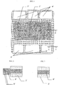
- FIG. 1 An embodiment of the process to prepare a 7-layer MEA with subgasket according to the present invention is illustrated in Figg. from 7-1 to 7-6.
- Fig. 7-1 is the front view of a subgasket sheet as prepared in the first step of the process according to this embodiment.
- (7) is the empty area
- (8) represents the subgasket
- (19) is the external perimeter of the subgasket.
- Fig. 7-2 is the front vew of the membrane side with a subgasket applied. (13) indicates the membrane area not covered by the subgakset, (8) is the subgasket of Fig. 7-1 , (9) is the external perimeter of the subgasket and (20) is the membrane area external to the perimeter (9).
- the preparation of this assembly represents the second step of the process according to this embodiment.
- Fig. 7-3 is a front view of the assembly on the membrane side with the subgasket of Fig. 7-2 cut in correspondence of a perimeter (10). (10) is equal to or lower than the external perimeter (9) of the subgasket (8) ( Fig. 7-1 ). (12) represent the openings, e.g. having a rectangular section as in the figure, made near the upper and lower edges of the area (13), (21) is the subgasket area obtained after the described cut. This represents the third step of the process according to this embodiment.
- Fig. 7-4 represents a plan view of the assembly of Fig. 7-3 with applied a second subgasket of Fig. 7-1 on the same side bearing the subgasket applied in step 2.
- a third subgas- ket is likewise applied on the other side of the assembly of Fig. 7-3 . This represents the fourth step of the process according to this embodiment.
- Fig. 7-5 represents a plan view of the assembly of Fig. 7-4 to which a gas diffusion electrode (22), formed of a catalytic layer, a microdiffusion layer and a gas macro- diffusion layer has been applied in correspondence with the area (13) in Fig. 7-2 .
- a second gas diffusion electrode is likewise applied on the other side of the assembly of Fig. 7-4 . All the parts covered by the subgasket (8) are as well shown in Fig 7-5 for a better understanding of the Figure. This represents the fifth step of the process according to this embodiment.
- Fig. 7-6 represents a plan view of the assembly of Fig. 7-5 wherein:
- the Applicant has unexpectedly and surprisingly found that by using the hot pressing with hot melt adhesive, MEA assemblies more lasting are obtained, even after several cycles in water at temperatures in the range 20°C-80°C.
- the Applicant has unexpectedly and surprisingly found that the MEA of the present invention, by using water having a low purity degree as cooling fluid, maintain substantially the same performances for long operating periods, even of the order of 6 months.
- the MEAs of the prior art within 10 days, show a content of polluting agents such as to compromise the performances in the electrochemical cells. It is indeed well known that the presence of polluting agents negatively affects the electrochemical cell perform- ances. See N-Yoshida et Al., Electrochemical Acta Vol. 43, 24, 3749-3754 (1998 ), A.
- the MEAs of the present invention can be used in electrochemical devices, in particular in fuel cells, with cooling fluids, for example formed of water, even having a lower purity than those used with the MEAs of the prior art. Therefore in the MEAs of the present invention, as cooling fluids, mixtures of water and high boiling solvents, for example water/glycols, can also be used in a wide temper- ature range, for example from temperatures lower than 0°C up to temperatures higher than 100°C, for example from -40°C to 160°C.
- the preparation of the ionomers used for preparing the membranes can be carried out with a radical polymerization process in mass, solution, suspension, emulsion. See USP 3,282,875 , USP 6, 639, 011 , USP 6, 555, 639 .
- the aqueous emulsion or microemulsion polymerization can for example be mentioned.
- the surfactants usable in these polymerizations are (per)fluorinated surfactants, for example salts (as defined below) of the perfluorooctanoic, perfluorononanoic, perfluorodecanoic acid, or their mixtures, etc., (per)fluoropolyethers with an acid end group (example -COOH, -SO 3 H), salified with NH 4 + or with alkaline metal cations, the other end group being (per)fluorinated, optionally containing one H or Cl atom.
- the number average molecular weights of the perfluoropolyether surfactants generally range between 300 and 1,800, preferably between 350 and 750.
- microemulsion polymerization is well known in the art. See USP 6,555,639 .
- aqueous emulsion polymerization is well known in the prior art. See USP 6,639,011 .
- R f preferably has one of the fol- lowing structures:
- the (per)fluoropolyethers R f are obtainable with the well known processes in the prior art, see for example the following patents herein incorporated by reference: US 3,665,041 , US 2,242,218 , US 3, 715, 378 and EP 239,123 .
- the fluoropolyethers functionalized with hydroxyl termination are for example obtained according to EP 148,482 , USP 3,810,874 .
- the functional end groups are obtained with the processes indicated in said patents.
- Chain transfer agents can be used in the polymerization.
- iodide and/or bromides of alkaline or alkaline-earth metals according to USP 5,173,553 .
- chain tansfer agents containing hydrogen as hydrocarbons, alcohols, in particular ethyl acetate and ethane are used.
- the polymerization initiators used in the process of the present invention are preferably radical inorganic initiators as, for example, ammonium and/or potassium and/or sodium persulphate, optionally in combination with ferrous, cuprous or silver salts.
- the procedures of the initiator feeding into the polymerization reactor can be in a continuous way or by a single addition at the beginning of the polymerization.
- the polymerization reaction is generally carried out at temperatures in the range 25°C-70°C, preferably 50°C-60°C, under pressure up to 30 bar (3 MPa), preferably higher than 8 bar (0.8 MPa) .
- Monomer (B) and optionally (B') is fed into the polymerization reactor in a continuous way or by steps.
- the ionomer is isolated by conventional methods as the coagulation by addi- tion of electrolytes or by freezing.
- a further object of the present invention is represented by electrochemical devices comprising the assemblies of the present invention, in particular fuel cells.
- a further object of the present invention is the use of the assemblies of the invention in electrochemical devices, in particular in fuel cells.
- PET having a 32 micron thickness treated on one side with Ethylen Vinyl Acetate (EVA) (Pertex Prima S.r.l., Milano) is used.
- EVA Ethylen Vinyl Acetate
- Fig. 7-2 is a front view of the assembly membrane + subgasket, described herein- after, from the membrane side on which the subgasket is applied.
- a portion (20) of the membrane is external to the subgasket perimeter (9), as illus- trated in Fig. 7.2 .
- the subgasket is adhered to the membrane by hot pressing, by using a heated press model COLLIN® Laboratory platen press Type 300M, under the following conditions:
- the first assembly is punched according to the shape represented in Fig. 7.3 , which is a front view of the first assembly seen from the subgasket side, by making holes of rectangular section (12).
- a second assembly is then prepared by adhering a subgasket sheet shown in Fig 7-1 on each side of the assembly of Fig 7-3 .
- the adhesion is obtained by hot pressing under the same conditions used for preparing the first assembly.
- the subgasket sheet have sizes higher than those of the first assembly.
- a gas diffusion electrode LT250EW (E-TEK) is applied.
- These gas diffusion electrodes containing a gas macrodiffusion layer and a gas microdiffusion layer, are directly supplied with a surface which has been treated with 0.5 mg/cm 2 of Pt supported on carbon and then with 0.5-0.7 mg/cm 2 of Nafion®.
- the treated surface is the one contacted with each of the membrane surfaces.
- the gas diffusion electrodes are attached by using in the hot pressing step the following conditions:
- the subsequent cooling is carried out by using a linear gradient from 150°C to 30°C for a time of 5 minutes main- taining the pressure of the hot pressing step.
- gas diffusion electrode area is greater than the active area which is coated.
- Fig. 7-5 is a plan view of the second assembly with the gas diffusion electrodes applied on the active area. The Figure shows that the perimeter of the gas diffusion electrode is greater than that of the active area.
- the second assembly completed with the gas diffusion electrodes is punched in correspondence of the holes (11) and the external perimeter (23), so as to obtain the MEA illustrated in Fig. 7-6 as plan view.
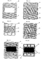
- the same kind of membrane and subgasket as in Example 1 is used.
- the first assembly is prepared by applying a subgasket sheet ( Fig. 8-1 ) to each membrane side, by using for the assembling the conditions indicated in the Example 1.
- the obtained assembly is illustrated in the plan view of Fig. 8-2 .
- the first assembly is then punched near the edges, by making rectangular section holes as shown in Fig. 8.3 , which is a plan view of the first assembly from the subgasket side, to obtain the openings (12).
- the second assembly is prepared, see Fig. 8-4 which is a plan view of the second assembly, by adhering on each side of the first assembly a subgasket sheet prepared as above ( Fig. 8-1 ).
- the adhesion is obtained by hot pressing under the same conditions described in Example 1, to obtain the second assembly.
- Fig. 8-4 shows that the two subgasket sheets have sizes such as to enclose the first assembly.
- a catalytic layer formed of a 1:1 mixture by weight of platinum supported on carbon and of ionomer Hyflon® Ion (Solvay Solexis) is applied by "DECAL" process at a temperature of about 150°C and at a pressure of about 20 bar ( USP 5,211,984 and USP 5,234,777 ).
- the perimeter of the catalytic area (25), or active area is coinciding with the perimeter of the empty area (7) as shown in Fig. 8-5 .
- the second assembly is lastly punched, obtaining the MEA illustrated as plan view in Fig. 8-6 .
- the MEA shows the following differences with respect to the first asembly ( Fig. 8-3 ):
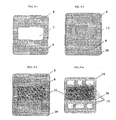
- Example 1 the application is carried out so that there is an area (20) of membrane external to the perimeter (9) of the subgasket as illustrated in Fig. 9-2 , which is a plan view of the assembly formed of the membrane with two subgaskets applied one on each side.
- the side of the subgasket treated with the EVA dispersion is the one contacted with the membrane.
- the assembling is carried out by contacting the membrane with the subgaskets by hot pressing and cooling as described in Example 1.
- a gas diffusion electrode LT250EW (E-TEK) is applied, comprising a gas macrodiffusion layer and a gas microdiffusion layer.
- E-TEK gas diffusion electrode
- Fig. 9-3 is a plan view of the assembly with the gas diffusion electrodes (22) applied on the active area.
- the Figure shows that the perimeter of (22) is greater than that of the active area.
- the assembly is then punched obtaining the MEA which is reported as plan view in Fig. 9-4 .
- PET is used, having a 125 micron thickness treated on one side with Ethylen Vinyl Acetate (EVA) (Perfex by PRIMA s.r.l., Milano).
- EVA Ethylen Vinyl Acetate
- the catalytic ink is prepared from a 1:1 mixture by weight of platinum supported on carbon (TEC10V50E by TANAKA, GP) with Hyflon® Ion ionomer (Solvay Solexis) in hydro-alcoholic solution.
- TEC10V50E platinum supported on carbon
- Hyflon® Ion ionomer Solvay Solexis
- hydro-alcoholic solution By using a stratifying knife (BRAIVE) a thickness of 100 micrometres of catalytic ink on a rectangular surface having 50 x 100 mm sides is spread on a non porous PTFE support.
- the catalytic ink is then dried in a ventilated oven for 30 minutes at 65°C. The process is likewise repeated on a second PTFE support.
- the two catalytic layers are transferred from the PTFE support to the ionomeric membrane.
- the transfer process is carried out under the following conditions: -temperature: 150°C; -pressure: 272 N/cm 2 ; -time: 300 seconds.
- a cooling step is then effected by applying a temperature gradient of (15°C)/(minute) for 5 minutes under unchanged pressure.
- a subgasket sheet having 50x120 mm sizes is applied, with the side adhes- ivized with EVA placed on the internal part, by using the following hot pressing conditions only on the overlapping area among subgasket-assembly-subgasket, so that each subgasket, after the adhesion, has a free edge (not attached to the membrane and to the other subgasket) having 50x20 mm sizes: - temperature: 100°C; - pressure: 98 N/cm 2 ; - time: 300 seconds.
- a linear gradient cooling between 100°C and 30°C follows, carried out in a total time of 10 minutes.
- This Example substantially represents the second step of the process of the present invention.
- a dynamometer ZP/Z2 by IMADA (Roma) is used.
- the sizes of the piece to be tested were of 50 x 100 mm.
- the assembly prepared according to the Example 5 resists a tensile stress 8 times higher than that of the assembly prepared according to the Example 4 (comparat- ive), before the delamination of the subgasket from the mem- brane. This shows that the direct adhesion of the subgasket to the membrane is stronger than when between the subgasket and the membrane a catalytic layer is interposed.
- Assemblies prepared according to the Examples 4 (comparative) and 5 are dipped into water and subjected to 20 cooling/heating cycles between 20°C and 80°C.
- the assembly prepared according to the Example 5 resists a tensile stress 15 times higher than that of the assembly prepared according to the Example 4 (comparative), before the delamination of one of the subgasket from the membrane.
- Example 6 The same comments as in Example 6 can be repeated.
- the device used is schematized in Fig. 10 .
- a MEA specimen according to the present invention (Example 1) the active area is cut along the edges and, after the gas dif- fusion layers have been removed, the potassium analysis is carried out by fluorescence with spectrophotometer XRF PW 2400 (Philips Analytical). By determining the heigth of the fluor- escence peak of the potassium K ⁇ at the wave length of 3.742 A° the cation content is estimated. This determination corresponds to the untreated reference specimen.
- Example 1 Another specimen of the 7-layer MEA according to the present invention (Example 1) is partially immersed in a solution having concentration 1000 ppm of KCl, so that the active area does not come into contact with the liquid. The experiment lasts 100 hours. At the end of the experiment, after having removed the gas diffusion layers, the active area is cut and analyzed for the potassium ion as above.
- the obtained results show that the MEAs of the present invention remain unchanged after prolonged contact times with water having a low purity degree, i.e. in this case a KCl dilute solution.
- the prior art MEAs are instead polluted by the used low purity water. Therefore the MEAs of the present invention have a long service life independently of the purity of the used cooling fluid. This represents an advantage in the confront of the MEAs of the prior art.
Landscapes
- Chemical & Material Sciences (AREA)
- General Chemical & Material Sciences (AREA)
- Electrochemistry (AREA)
- Chemical Kinetics & Catalysis (AREA)
- Engineering & Computer Science (AREA)
- Sustainable Development (AREA)
- Sustainable Energy (AREA)
- Life Sciences & Earth Sciences (AREA)
- Manufacturing & Machinery (AREA)
- Materials Engineering (AREA)
- Crystallography & Structural Chemistry (AREA)
- Fuel Cell (AREA)
- Inert Electrodes (AREA)
- Electrodes For Compound Or Non-Metal Manufacture (AREA)
Applications Claiming Priority (1)
| Application Number | Priority Date | Filing Date | Title |
|---|---|---|---|
| IT002509A ITMI20052509A1 (it) | 2005-12-28 | 2005-12-28 | Assemblati per dispositivi elettrochimici |
Publications (3)
| Publication Number | Publication Date |
|---|---|
| EP1806803A2 EP1806803A2 (en) | 2007-07-11 |
| EP1806803A3 EP1806803A3 (en) | 2017-03-08 |
| EP1806803B1 true EP1806803B1 (en) | 2020-04-29 |
Family
ID=37951879
Family Applications (1)
| Application Number | Title | Priority Date | Filing Date |
|---|---|---|---|
| EP06026267.2A Active EP1806803B1 (en) | 2005-12-28 | 2006-12-19 | Assemblies for electrochemical devices |
Country Status (7)
| Country | Link |
|---|---|
| US (1) | US7943267B2 (it) |
| EP (1) | EP1806803B1 (it) |
| JP (1) | JP5209871B2 (it) |
| KR (1) | KR101432578B1 (it) |
| CN (1) | CN1992406B (it) |
| IT (1) | ITMI20052509A1 (it) |
| RU (1) | RU2006145381A (it) |
Families Citing this family (10)
| Publication number | Priority date | Publication date | Assignee | Title |
|---|---|---|---|---|
| US8268510B2 (en) * | 2008-12-22 | 2012-09-18 | GM Global Technology Operations LLC | Fuel cell fabrication using photopolymer based processes |
| US8389177B2 (en) * | 2008-12-22 | 2013-03-05 | Gm Global Technology Operations | Combined subgasket and membrane support |
| JP5706443B2 (ja) * | 2009-12-22 | 2015-04-22 | スリーエム イノベイティブ プロパティズ カンパニー | サブガスケット付スリフトされた膜を組み込んだ燃料電池のサブアセンブリ |
| US8399150B2 (en) | 2010-06-23 | 2013-03-19 | GM Global Technology Operations LLC | Integrated fuel cell assembly and method of making |
| KR20140049309A (ko) * | 2012-10-17 | 2014-04-25 | 삼성전기주식회사 | 터치 패널 및 이의 제조방법 |
| JP6748640B2 (ja) | 2014-10-20 | 2020-09-02 | ソルベイ スペシャルティ ポリマーズ イタリー エス.ピー.エー. | プロトン交換膜用の液体組成物 |
| KR101637711B1 (ko) * | 2014-10-30 | 2016-07-07 | 현대자동차주식회사 | 연료전지의 고분자 전해질막-전극 접합체용 전극의 분리방법과 그 장치 |
| FR3053840B1 (fr) | 2016-07-06 | 2018-08-17 | Commissariat A L'energie Atomique Et Aux Energies Alternatives | Pile a combustible comprenant un assemblage membrane/electrodes incluant une couche capacitive |
| CN111094438B (zh) | 2017-09-14 | 2022-11-08 | 3M创新有限公司 | 具有磺酰基侧基的氟化共聚物以及包含其的组合物和制品 |
| DE102020124576A1 (de) * | 2020-09-22 | 2022-03-24 | Audi Aktiengesellschaft | Verfahren zur Herstellung eines wenigstens zweilagigen Laminats einer Membranelektrodeneinheit |
Family Cites Families (43)
| Publication number | Priority date | Publication date | Assignee | Title |
|---|---|---|---|---|
| US2242218A (en) * | 1936-08-14 | 1941-05-20 | Auer Laszlo | Sizing textiles |
| US3282875A (en) * | 1964-07-22 | 1966-11-01 | Du Pont | Fluorocarbon vinyl ether polymers |
| DE1745169B2 (de) * | 1967-02-09 | 1977-04-21 | Montecatini Edison S.P.A., Mailand (Italien) | Fluorierte lineare polyaether und verfahren zu ihrer herstellung |
| US3665041A (en) * | 1967-04-04 | 1972-05-23 | Montedison Spa | Perfluorinated polyethers and process for their preparation |
| US3810874A (en) * | 1969-03-10 | 1974-05-14 | Minnesota Mining & Mfg | Polymers prepared from poly(perfluoro-alkylene oxide) compounds |
| US4035565A (en) * | 1975-03-27 | 1977-07-12 | E. I. Du Pont De Nemours And Company | Fluoropolymer containing a small amount of bromine-containing olefin units |
| JPS53125491A (en) * | 1977-04-08 | 1978-11-01 | Daikin Ind Ltd | Fluorine-containing polymer easily curable and its curable composition |
| US4433082A (en) * | 1981-05-01 | 1984-02-21 | E. I. Du Pont De Nemours And Company | Process for making liquid composition of perfluorinated ion exchange polymer, and product thereof |
| CA1198882A (en) * | 1982-04-08 | 1986-01-07 | Marley Tile A.G. | Roof tiles |
| EP0148482B1 (en) | 1983-12-26 | 1992-03-25 | Daikin Industries, Limited | Process for preparing halogen-containing polyether |
| US4564662A (en) * | 1984-02-23 | 1986-01-14 | Minnesota Mining And Manufacturing Company | Fluorocarbon elastomer |
| DE3662142D1 (en) | 1985-03-28 | 1989-03-30 | Daikin Ind Ltd | Novel fluorovinyl ether and copolymer comprising the same |
| US4610762A (en) * | 1985-05-31 | 1986-09-09 | The Dow Chemical Company | Method for forming polymer films having bubble release surfaces |
| IT1187684B (it) * | 1985-07-08 | 1987-12-23 | Montefluos Spa | Procedimento per la preparazione di fluoroelastomeri vulcanizzabili e prodotti cosi' ottenuti |
| US4694045A (en) * | 1985-12-11 | 1987-09-15 | E. I. Du Pont De Nemours And Company | Base resistant fluoroelastomers |
| IT1188635B (it) | 1986-03-27 | 1988-01-20 | Ausimont Spa | Lubrificanti per fluoropolieterei interni per mezzi magnetici di registrazione |
| JPS63304009A (ja) * | 1987-06-04 | 1988-12-12 | Nippon Mektron Ltd | パ−オキサイド加硫可能な含フッ素エラストマ−の製造方法 |
| IT1235545B (it) * | 1989-07-10 | 1992-09-09 | Ausimont Srl | Fluoroelastomeri dotati di migliore processabilita' e procedimento di preparazione |
| IT1231174B (it) | 1989-07-24 | 1991-11-22 | Ausimont Srl | Mescole vulcanizzabili di fluoroelastomeri contenenti bromo o iodio e di perossidi organici |
| JP2581950Y2 (ja) * | 1991-12-18 | 1998-09-24 | 本田技研工業株式会社 | 燃料電池マニホールド板 |
| IT1265461B1 (it) | 1993-12-29 | 1996-11-22 | Ausimont Spa | Fluoroelastomeri comprendenti unita' monomeriche derivanti da una bis-olefina |
| WO1997040924A1 (en) | 1996-04-30 | 1997-11-06 | W.L. Gore & Associates, Inc. | Integral ion-exchange composite membranes |
| US6592934B2 (en) * | 1996-12-27 | 2003-07-15 | Japan Storage Battery Co., Ltd. | Gas diffusion electrode, solid polymer electrolyte membrane, process for the production thereof and solid polymer electrolyte fuel cell |
| JPH10199551A (ja) * | 1997-01-06 | 1998-07-31 | Honda Motor Co Ltd | 燃料電池構造体およびその製造方法 |
| US5910378A (en) | 1997-10-10 | 1999-06-08 | Minnesota Mining And Manufacturing Company | Membrane electrode assemblies |
| JPH11204122A (ja) * | 1998-01-19 | 1999-07-30 | Toshiba Corp | 固体高分子電解質型燃料電池 |
| IT1303779B1 (it) | 1998-11-23 | 2001-02-23 | Ausimont Spa | Preparazione di soluzioni di polimeri fluorurati solfonici. |
| DE19926026A1 (de) * | 1999-05-28 | 2000-11-30 | Heliocentris Energiesysteme | Membran-Elektroden-Einheit für Brennstoffzellen u. dgl. |
| JP4576646B2 (ja) * | 1999-09-30 | 2010-11-10 | アイシン精機株式会社 | 燃料電池 |
| DE10014650A1 (de) | 2000-03-24 | 2001-10-04 | Wacker Siltronic Halbleitermat | Halbleiterscheibe aus Silicium und Verfahren zur Herstellung der Halbleiterscheibe |
| IT1318594B1 (it) * | 2000-06-23 | 2003-08-27 | Ausimont Spa | Processo di polimerizzazione di monomeri solfonici. |
| IT1318593B1 (it) * | 2000-06-23 | 2003-08-27 | Ausimont Spa | Ionomeri fluorurati. |
| AU2001260606B2 (en) * | 2000-11-21 | 2006-10-19 | Nok Corporation | Constituent part for fuel cell |
| ITMI20010384A1 (it) | 2001-02-26 | 2002-08-26 | Ausimont Spa | Membrane idrofiliche porose |
| GB0112021D0 (en) * | 2001-05-17 | 2001-07-11 | Johnson Matthey Plc | Substrate |
| JP2003123801A (ja) * | 2001-10-16 | 2003-04-25 | Matsushita Electric Ind Co Ltd | 高分子電解質型積層燃料電池 |
| ITMI20012744A1 (it) * | 2001-12-21 | 2003-06-21 | Ausimont Spa | Processo di polimerizzazione di monomeri solfonici |
| US6716549B2 (en) * | 2001-12-27 | 2004-04-06 | Avista Laboratories, Inc. | Fuel cell having metalized gas diffusion layer |
| US20040096723A1 (en) * | 2002-11-14 | 2004-05-20 | 3M Innovative Properties Company | Fuel cell gasket |
| US6716550B1 (en) * | 2002-12-20 | 2004-04-06 | Ballard Power Systems Inc. | Sealing membrane electrode assemblies for electrochemical fuel cells |
| CA2477358C (en) | 2003-08-22 | 2012-03-27 | Matsushita Electric Industrial Co., Ltd. | Polymer electrolyte fuel cell |
| ITMI20031972A1 (it) | 2003-10-14 | 2005-04-15 | Nuvera Fuel Cells Europ Srl | Cella a combustibile a membrana con funzionamento stabile nel tempo |
| ITMI20040789A1 (it) | 2004-04-22 | 2004-07-22 | Solvay Solexis Spa | Membrane fluorurate |
-
2005
- 2005-12-28 IT IT002509A patent/ITMI20052509A1/it unknown
-
2006
- 2006-12-19 EP EP06026267.2A patent/EP1806803B1/en active Active
- 2006-12-21 RU RU2006145381/09A patent/RU2006145381A/ru not_active Application Discontinuation
- 2006-12-22 JP JP2006345998A patent/JP5209871B2/ja active Active
- 2006-12-26 KR KR1020060133781A patent/KR101432578B1/ko active IP Right Grant
- 2006-12-27 US US11/645,539 patent/US7943267B2/en not_active Expired - Fee Related
- 2006-12-28 CN CN2006100647322A patent/CN1992406B/zh active Active
Non-Patent Citations (1)
| Title |
|---|
| None * |
Also Published As
| Publication number | Publication date |
|---|---|
| EP1806803A2 (en) | 2007-07-11 |
| ITMI20052509A1 (it) | 2007-06-29 |
| JP5209871B2 (ja) | 2013-06-12 |
| RU2006145381A (ru) | 2008-06-27 |
| KR101432578B1 (ko) | 2014-08-22 |
| KR20070070082A (ko) | 2007-07-03 |
| CN1992406A (zh) | 2007-07-04 |
| JP2007180030A (ja) | 2007-07-12 |
| EP1806803A3 (en) | 2017-03-08 |
| US20070148517A1 (en) | 2007-06-28 |
| US7943267B2 (en) | 2011-05-17 |
| CN1992406B (zh) | 2012-07-04 |
Similar Documents
| Publication | Publication Date | Title |
|---|---|---|
| EP1806803B1 (en) | Assemblies for electrochemical devices | |
| EP1804325B1 (en) | Process for obtaining CCM with subgaskets | |
| US8097383B2 (en) | Electrolyte material for polymer electrolyte fuel cells, electrolyte membrane and membrane/electrode assembly | |
| CN102471412B (zh) | 电解质材料、液状组合物及固体高分子型燃料电池用膜电极接合体 | |
| US9190687B2 (en) | Assemblies for electrochemical devices | |
| US6896777B2 (en) | Porous hydrophilic membranes | |
| EP2270818B1 (en) | Polyelectrolyte and process for producing the polyelectrolyte | |
| WO2013157395A1 (ja) | 電解質材料、液状組成物および固体高分子形燃料電池用膜電極接合体 | |
| CN101048434A (zh) | 电解质材料、电解质膜及固体高分子型燃料电池用膜电极接合体 | |
| CN109790244B (zh) | 聚合物、固体高分子电解质膜及膜电极接合体 | |
| WO2008000719A1 (en) | Assemblies for electrochemical devices | |
| WO2022210571A1 (ja) | 電解質材料、膜電極接合体および固体高分子形燃料電池 | |
| WO2008000724A1 (en) | Assemblies for electrochemical devices |
Legal Events
| Date | Code | Title | Description |
|---|---|---|---|
| PUAI | Public reference made under article 153(3) epc to a published international application that has entered the european phase |
Free format text: ORIGINAL CODE: 0009012 |
|
| AK | Designated contracting states |
Kind code of ref document: A2 Designated state(s): AT BE BG CH CY CZ DE DK EE ES FI FR GB GR HU IE IS IT LI LT LU LV MC NL PL PT RO SE SI SK TR |
|
| AX | Request for extension of the european patent |
Extension state: AL BA HR MK YU |
|
| RAP1 | Party data changed (applicant data changed or rights of an application transferred) |
Owner name: SOLVAY SOLEXIS S.P.A. |
|
| RAP1 | Party data changed (applicant data changed or rights of an application transferred) |
Owner name: SOLVAY SPECIALTY POLYMERS ITALY S.P.A. |
|
| RIC1 | Information provided on ipc code assigned before grant |
Ipc: H01M 8/10 20060101ALI20161018BHEP Ipc: H01M 4/92 20060101AFI20161018BHEP Ipc: H01M 8/02 20060101ALI20161018BHEP |
|
| PUAL | Search report despatched |
Free format text: ORIGINAL CODE: 0009013 |
|
| AK | Designated contracting states |
Kind code of ref document: A3 Designated state(s): AT BE BG CH CY CZ DE DK EE ES FI FR GB GR HU IE IS IT LI LT LU LV MC NL PL PT RO SE SI SK TR |
|
| AX | Request for extension of the european patent |
Extension state: AL BA HR MK RS |
|
| RIC1 | Information provided on ipc code assigned before grant |
Ipc: H01M 8/10 20160101ALI20170127BHEP Ipc: H01M 8/02 20160101ALI20170127BHEP Ipc: H01M 4/92 20060101AFI20170127BHEP |
|
| STAA | Information on the status of an ep patent application or granted ep patent |
Free format text: STATUS: REQUEST FOR EXAMINATION WAS MADE |
|
| 17P | Request for examination filed |
Effective date: 20170908 |
|
| AKX | Designation fees paid |
Designated state(s): CH DE FR GB IT LI NL |
|
| AXX | Extension fees paid |
Extension state: MK Extension state: HR Extension state: BA Extension state: AL Extension state: RS |
|
| STAA | Information on the status of an ep patent application or granted ep patent |
Free format text: STATUS: EXAMINATION IS IN PROGRESS |
|
| 17Q | First examination report despatched |
Effective date: 20181016 |
|
| RIC1 | Information provided on ipc code assigned before grant |
Ipc: H01M 4/92 20060101AFI20190520BHEP Ipc: H01M 8/1067 20160101ALI20190520BHEP Ipc: H01M 8/0276 20160101ALI20190520BHEP Ipc: H01M 8/0271 20160101ALI20190520BHEP Ipc: H01M 8/1004 20160101ALI20190520BHEP Ipc: H01M 8/1018 20160101ALN20190520BHEP Ipc: H01M 8/1039 20160101ALI20190520BHEP Ipc: H01M 8/0273 20160101ALI20190520BHEP Ipc: H01M 8/1023 20160101ALI20190520BHEP |
|
| RIC1 | Information provided on ipc code assigned before grant |
Ipc: H01M 8/1067 20160101ALI20190905BHEP Ipc: H01M 4/92 20060101AFI20190905BHEP Ipc: H01M 8/0273 20160101ALI20190905BHEP Ipc: H01M 8/1039 20160101ALI20190905BHEP Ipc: H01M 8/0276 20160101ALI20190905BHEP Ipc: H01M 8/1023 20160101ALI20190905BHEP Ipc: H01M 8/0271 20160101ALI20190905BHEP Ipc: H01M 8/1004 20160101ALI20190905BHEP Ipc: H01M 8/1018 20160101ALN20190905BHEP |
|
| REG | Reference to a national code |
Ref country code: DE Ref legal event code: R079 Ref document number: 602006059360 Country of ref document: DE Free format text: PREVIOUS MAIN CLASS: H01M0008100000 Ipc: H01M0004920000 |
|
| GRAP | Despatch of communication of intention to grant a patent |
Free format text: ORIGINAL CODE: EPIDOSNIGR1 |
|
| STAA | Information on the status of an ep patent application or granted ep patent |
Free format text: STATUS: GRANT OF PATENT IS INTENDED |
|
| RIC1 | Information provided on ipc code assigned before grant |
Ipc: H01M 8/1023 20160101ALI20191029BHEP Ipc: H01M 8/0271 20160101ALI20191029BHEP Ipc: H01M 8/0273 20160101ALI20191029BHEP Ipc: H01M 8/1004 20160101ALI20191029BHEP Ipc: H01M 8/1039 20160101ALI20191029BHEP Ipc: H01M 8/0276 20160101ALI20191029BHEP Ipc: H01M 8/1067 20160101ALI20191029BHEP Ipc: H01M 8/1018 20160101ALN20191029BHEP Ipc: H01M 4/92 20060101AFI20191029BHEP |
|
| INTG | Intention to grant announced |
Effective date: 20191121 |
|
| GRAS | Grant fee paid |
Free format text: ORIGINAL CODE: EPIDOSNIGR3 |
|
| GRAA | (expected) grant |
Free format text: ORIGINAL CODE: 0009210 |
|
| STAA | Information on the status of an ep patent application or granted ep patent |
Free format text: STATUS: THE PATENT HAS BEEN GRANTED |
|
| AK | Designated contracting states |
Kind code of ref document: B1 Designated state(s): CH DE FR GB IT LI NL |
|
| REG | Reference to a national code |
Ref country code: GB Ref legal event code: FG4D |
|
| REG | Reference to a national code |
Ref country code: CH Ref legal event code: EP |
|
| REG | Reference to a national code |
Ref country code: DE Ref legal event code: R096 Ref document number: 602006059360 Country of ref document: DE |
|
| REG | Reference to a national code |
Ref country code: NL Ref legal event code: MP Effective date: 20200429 |
|
| PG25 | Lapsed in a contracting state [announced via postgrant information from national office to epo] |
Ref country code: NL Free format text: LAPSE BECAUSE OF FAILURE TO SUBMIT A TRANSLATION OF THE DESCRIPTION OR TO PAY THE FEE WITHIN THE PRESCRIBED TIME-LIMIT Effective date: 20200429 |
|
| PG25 | Lapsed in a contracting state [announced via postgrant information from national office to epo] |
Ref country code: IT Free format text: LAPSE BECAUSE OF FAILURE TO SUBMIT A TRANSLATION OF THE DESCRIPTION OR TO PAY THE FEE WITHIN THE PRESCRIBED TIME-LIMIT Effective date: 20200429 |
|
| REG | Reference to a national code |
Ref country code: DE Ref legal event code: R097 Ref document number: 602006059360 Country of ref document: DE |
|
| PLBE | No opposition filed within time limit |
Free format text: ORIGINAL CODE: 0009261 |
|
| STAA | Information on the status of an ep patent application or granted ep patent |
Free format text: STATUS: NO OPPOSITION FILED WITHIN TIME LIMIT |
|
| 26N | No opposition filed |
Effective date: 20210201 |
|
| REG | Reference to a national code |
Ref country code: CH Ref legal event code: PL |
|
| PG25 | Lapsed in a contracting state [announced via postgrant information from national office to epo] |
Ref country code: CH Free format text: LAPSE BECAUSE OF NON-PAYMENT OF DUE FEES Effective date: 20201231 Ref country code: LI Free format text: LAPSE BECAUSE OF NON-PAYMENT OF DUE FEES Effective date: 20201231 |
|
| P01 | Opt-out of the competence of the unified patent court (upc) registered |
Effective date: 20230624 |
|
| PGFP | Annual fee paid to national office [announced via postgrant information from national office to epo] |
Ref country code: GB Payment date: 20231102 Year of fee payment: 18 |
|
| PGFP | Annual fee paid to national office [announced via postgrant information from national office to epo] |
Ref country code: FR Payment date: 20231108 Year of fee payment: 18 Ref country code: DE Payment date: 20231031 Year of fee payment: 18 |