EP1804635B1 - Sac filtrant d'aspirateur et utilisation d'un sac filtrant d'aspirateur - Google Patents
Sac filtrant d'aspirateur et utilisation d'un sac filtrant d'aspirateur Download PDFInfo
- Publication number
- EP1804635B1 EP1804635B1 EP06818737A EP06818737A EP1804635B1 EP 1804635 B1 EP1804635 B1 EP 1804635B1 EP 06818737 A EP06818737 A EP 06818737A EP 06818737 A EP06818737 A EP 06818737A EP 1804635 B1 EP1804635 B1 EP 1804635B1
- Authority
- EP
- European Patent Office
- Prior art keywords
- vacuum cleaner
- filter bag
- material layer
- cleaner filter
- deflection device
- Prior art date
- Legal status (The legal status is an assumption and is not a legal conclusion. Google has not performed a legal analysis and makes no representation as to the accuracy of the status listed.)
- Active
Links
- 239000000463 material Substances 0.000 claims description 301
- 239000000835 fiber Substances 0.000 claims description 53
- 239000004745 nonwoven fabric Substances 0.000 claims description 17
- 239000000123 paper Substances 0.000 claims description 11
- 230000005484 gravity Effects 0.000 claims description 5
- 239000004033 plastic Substances 0.000 claims description 4
- 229920003023 plastic Polymers 0.000 claims description 4
- 238000011064 split stream procedure Methods 0.000 claims 4
- 239000007787 solid Substances 0.000 claims 3
- 239000011888 foil Substances 0.000 claims 2
- 239000000155 melt Substances 0.000 claims 2
- 239000011087 paperboard Substances 0.000 claims 2
- 239000000428 dust Substances 0.000 abstract description 16
- 239000010410 layer Substances 0.000 description 212
- 239000002245 particle Substances 0.000 description 8
- 238000005452 bending Methods 0.000 description 6
- 230000000694 effects Effects 0.000 description 6
- 238000007789 sealing Methods 0.000 description 5
- 238000003466 welding Methods 0.000 description 5
- 239000002131 composite material Substances 0.000 description 4
- 238000004519 manufacturing process Methods 0.000 description 4
- 239000004743 Polypropylene Substances 0.000 description 3
- 238000011161 development Methods 0.000 description 3
- 230000018109 developmental process Effects 0.000 description 3
- 238000005259 measurement Methods 0.000 description 3
- 238000012360 testing method Methods 0.000 description 3
- 239000000853 adhesive Substances 0.000 description 2
- 230000001070 adhesive effect Effects 0.000 description 2
- 230000006378 damage Effects 0.000 description 2
- 238000009792 diffusion process Methods 0.000 description 2
- 229920001971 elastomer Polymers 0.000 description 2
- 239000012065 filter cake Substances 0.000 description 2
- 239000003292 glue Substances 0.000 description 2
- 238000002347 injection Methods 0.000 description 2
- 239000007924 injection Substances 0.000 description 2
- 230000035699 permeability Effects 0.000 description 2
- -1 polypropylene Polymers 0.000 description 2
- 229920001155 polypropylene Polymers 0.000 description 2
- 239000011148 porous material Substances 0.000 description 2
- 239000011241 protective layer Substances 0.000 description 2
- 229920001410 Microfiber Polymers 0.000 description 1
- 238000005299 abrasion Methods 0.000 description 1
- 238000007792 addition Methods 0.000 description 1
- 238000004026 adhesive bonding Methods 0.000 description 1
- 238000013459 approach Methods 0.000 description 1
- 206010061592 cardiac fibrillation Diseases 0.000 description 1
- 230000001427 coherent effect Effects 0.000 description 1
- 238000010276 construction Methods 0.000 description 1
- 230000007423 decrease Effects 0.000 description 1
- 230000003247 decreasing effect Effects 0.000 description 1
- 230000008021 deposition Effects 0.000 description 1
- 230000006866 deterioration Effects 0.000 description 1
- 238000009826 distribution Methods 0.000 description 1
- 238000010410 dusting Methods 0.000 description 1
- 239000000806 elastomer Substances 0.000 description 1
- 238000005516 engineering process Methods 0.000 description 1
- 238000001125 extrusion Methods 0.000 description 1
- 239000004744 fabric Substances 0.000 description 1
- 230000005294 ferromagnetic effect Effects 0.000 description 1
- 230000002600 fibrillogenic effect Effects 0.000 description 1
- 239000006260 foam Substances 0.000 description 1
- 238000003780 insertion Methods 0.000 description 1
- 230000037431 insertion Effects 0.000 description 1
- 238000007689 inspection Methods 0.000 description 1
- 238000011835 investigation Methods 0.000 description 1
- 230000007774 longterm Effects 0.000 description 1
- 210000004072 lung Anatomy 0.000 description 1
- 239000003658 microfiber Substances 0.000 description 1
- 238000004806 packaging method and process Methods 0.000 description 1
- 239000002243 precursor Substances 0.000 description 1
- 238000011045 prefiltration Methods 0.000 description 1
- 230000001105 regulatory effect Effects 0.000 description 1
- 238000003860 storage Methods 0.000 description 1
- 238000002604 ultrasonography Methods 0.000 description 1
- 238000009827 uniform distribution Methods 0.000 description 1
Images


Classifications
-
- A—HUMAN NECESSITIES
- A47—FURNITURE; DOMESTIC ARTICLES OR APPLIANCES; COFFEE MILLS; SPICE MILLS; SUCTION CLEANERS IN GENERAL
- A47L—DOMESTIC WASHING OR CLEANING; SUCTION CLEANERS IN GENERAL
- A47L9/00—Details or accessories of suction cleaners, e.g. mechanical means for controlling the suction or for effecting pulsating action; Storing devices specially adapted to suction cleaners or parts thereof; Carrying-vehicles specially adapted for suction cleaners
- A47L9/10—Filters; Dust separators; Dust removal; Automatic exchange of filters
- A47L9/14—Bags or the like; Rigid filtering receptacles; Attachment of, or closures for, bags or receptacles
- A47L9/1427—Means for mounting or attaching bags or filtering receptacles in suction cleaners; Adapters
- A47L9/1436—Connecting plates, e.g. collars, end closures
- A47L9/1445—Connecting plates, e.g. collars, end closures with closure means
- A47L9/1454—Self-sealing closures, e.g. valves
Definitions
- the invention relates to a vacuum cleaner filter bag and the use of a vacuum cleaner filter bag in a vacuum cleaner.
- the EP 0 960 645 shows the EP 0 960 645 a multi-layer vacuum cleaner filter bag assembly, wherein in the air flow direction, a coarse filter layer is disposed in front of a fine filter layer.
- the coarse filter layer should have a relatively high thickness and a high pore volume. This can delay a clogging of the bag over a longer period of time.
- the EP 1 123 724 shows a multi-layer vacuum cleaner bag, which comprises a support layer of paper, the raw gas side is covered by a pre-filter made of microfibers, which performs the function of a release layer and is temporarily lifted from the support layer. This separating layer completely covers the base layer to ensure that the filter bag is sufficiently stable and filter-effective even when the paper layer is completely destroyed.
- a protective layer in the form of a strip is provided inside the vacuum cleaner filter bag, which is also intended to prevent damage to the vacuum cleaner filter bag.
- This protective layer is arranged such that particles entering the filter bag through an inlet opening impinge directly on the strip, so that the subsequent layer remains protected.
- a filter bag is known in which a layer of abrasion resistant material is arranged on the inside.
- the dust cleaner also has a deflection screen.
- a deflector and a sheet of material having an unconnected portion enclosing a portion of the edge of the sheet of material provides a substantial improvement in the life of the vacuum cleaner filter bag.
- the deflection device ensures that an airflow entering through an inlet opening of the vacuum cleaner filter bag does not strike directly against the inside of the bag opposite the inlet opening. An incoming air stream may thus flow under the at least partially unconnected with the vacuum cleaner filter bag material layer, so that it is at least partially spaced from the inside of the vacuum cleaner filter bag.
- This air flow can continue to pass through the material layer away from the bag wall in the direction of the bag interior, resulting in a highly advantageous distribution of the filter cake inside the bag, whereby the service life of the vacuum cleaner filter bag is significantly increased.
- the special feature is therefore that the material layer can at least partially be underflowed by an air flow, which can then pass through the material layer into the interior of the bag again.
- connection of the material layer to the at least one point can be provided on the side facing the inlet opening and / or the side of the material layer facing away from the inlet opening, in FIG.
- the unconnected part is not connected to the vacuum cleaner filter bag either on the side facing the inlet opening or on the side remote from the inlet opening.
- the at least one part forms a coherent piece of the material layer.
- the edge of the material layer comprises the side edges of the material layer; For example, if the material layer continues to have a slot, the edge also includes the edges of the material layer at the slot.
- the material layer may have a smaller area than the area of the inside of the material layer. This advantageously enables an underflow of the material layer.
- the area of the at least one part can make up at least 20% of the area of the material layer.
- a convex amount can be formed on a surface of the material layer.
- convex has the following meaning.
- a lot M ⁇ R 2 is called convex if with every two points P and Q from this set also all points of the connection path between P and Q belong to M.
- the term convex is thus used in the conventional sense, as it is for example in IN Bronstein, KA Semendjajew, Taschenbuch der Mathematik, 25th edition 1991, BG Teubner Verlagsgesellschaft and Verlag Nauka, chapter 3.1.2 , is mentioned.
- the convex sets in the plane include triangles, rectangles, or slices. This meaning is decisive for a flat material layer.
- a set M on a two-dimensional, possibly curved surface in three-dimensional space is called convex, if with two points P and Q from this set also all points of the connection path on the surface between P and Q belong to M. This meaning is decisive for a curved material layer.
- the vacuum cleaner filter bag may be formed as a flat bag. In this case, it is preferable to judge the convexity in the flat state of the vacuum cleaner filter bag.
- the at least one part may include the projection point resulting from a perpendicular projection of the geometrical center of gravity of the material layer onto the surface on one side of the material layer.
- the unconnected part extends from one edge of the material layer to its middle.
- a relatively large part of the material layer is unconnected, which increases the effect of the material layer in combination with the deflection device and results in an additional increase in service life.
- the at least one part may include a path leading through the projection point on the surface whose end points each form the edge of the material layer.
- the part extends from one part of the edge to another part of the edge. This makes it possible for an air stream to flow through under the material layer.
- the at least one part may include at least 10% of the edge of the sheet of material.
- the at least one part may include at least 30%, in particular at least 50%, in particular at least 70%, in particular at least 90% and / or in particular at most 95%, in particular at most 70%, of the edge of the material layer.
- the at least one part, in particular the convex amount formed thereby, can make up an area of at least 40%, in particular at least 60%, in particular at least 80%, of the surface of the material layer.
- the material layer may have a polygonal, in particular quadrilateral, shape, and the at least one part may include a part of at least two, in particular opposite, side edges of the material layer.
- the material layer may be connected to the vacuum cleaner filter bag at a predetermined amount of points, preferably at exactly two points, and / or at two seams of the vacuum cleaner filter bag.
- the material layer may have a rectangular shape and be connected to the vacuum cleaner filter bag only along two, in particular opposite, side edges, in particular the short sides.
- the material layer can be glued or welded to the vacuum cleaner filter bag, in particular the inside of the bag, for example.
- the material layer can comprise a nonwoven fabric, for example comprising a fine-fiber fleece (meltblown), a spunbond, a wet-laid nonwoven and / or a dried fleece, a paper or an air-permeable film, for example a perforated or slotted film.
- a nonwoven fabric for example comprising a fine-fiber fleece (meltblown), a spunbond, a wet-laid nonwoven and / or a dried fleece, a paper or an air-permeable film, for example a perforated or slotted film.
- the strip of material may have an air permeability of 100-10000 l / (m 2 s), more preferably of 1000-8000 l / (m 2 s), most preferably 1500-5000 l / (m 2 s).
- the material layer may have an area of 10 - 80%, preferably 15 - 30% of the area of the inside of the bag.
- the material layer may be connected to the inlet opening of the vacuum cleaner filter bag opposite to the vacuum cleaner filter bag of the vacuum cleaner filter bag.
- the at least one part may have at least one slot. Through such a slot, an underflow of the material layer is further promoted. If the material layer has at least one slot, in particular with a large length, the material layer can, for example, cover the entire surface of the inside of the vacuum cleaner filter bag. Nevertheless, an underflow is ensured by the at least one slot.
- the material layer may have a plurality of slots. In a flat bag, the material layer, if it has at least one slot, cover a bag wall, in particular the bag wall opposite the inlet opening over the entire surface.
- the vacuum cleaner filter bag can be designed as a flat bag with two rectangular filter material layers connected to one another along the edge.
- the air-permeable material layer may be connected to the filter material layer opposite the inlet opening of the vacuum cleaner filter bag, in particular in the center.
- the material layer may have a rectangular shape with a width of 10-80%, preferably 25-45%, the width of the associated filter material layer and / or a length of 60-100%, preferably 100%, of the length of the associated filter material layer.
- the material layer may comprise at least one laminate, in particular an SMS.
- a laminate several layers of material are bonded together. For example, a spunbond, a meltblown and a spunbond are linked together in an SMS.
- the material layer may comprise a film fiber net.
- film fiber networks arise, for example, in the fibrillation of extruded films and provide a precursor of film fiber nonwovens (see eg " Nonwovens ", W. Albrecht, F. Fuchs and W. Kittelmann, Wiley VCH, Weinheim, 2000 ).
- the material layer may include netting.
- Such a fiber network can be obtained by extrusion and deposition of the fibers.
- the material layer may comprise, in the vacuum cleaner filter bags described above, individual interconnected fibers or may consist of individual interconnected fibers.
- the directions of the longitudinal axes of the individual non-bonded fibers may include an angle of less than 45 ° to each other.
- the fibers can therefore be arranged parallel to one another.
- unconnected and unconnected single fiber is meant here that the fibers are not interconnected substantially along their longitudinal direction. However, this should not be ruled out that they can have a local connection to one another via the at least one connection point with the vacuum cleaner filter bag.
- the fibers cited in this application have relatively large fiber lengths of a few centimeters up to the length or width of the vacuum cleaner filter bag.
- the non-interconnected fibers may be staple fibers, in particular polypropylene.
- the fibers may be oriented substantially parallel to the direction of air flow at the inlet opening prior to deflection by the deflector or perpendicular to that direction, or may include an angle substantially between 0 ° and 90 ° to this direction substantially parallel to one another.
- the fibers may thus be arranged in particular parallel to one of the edges. These individual fibers can be arranged side by side with or without spacing from one another or else overlapping one another.
- Each of the fibers has first and second ends in the fiber longitudinal direction and may be attached to both the first end and the second end with the vacuum cleaner filter bag be connected.
- the connection may be formed by a transverse connection over the ends, such as a transverse welding or adhesive seam.
- all or some of the fibers perpendicular to the fiber longitudinal direction may be connected to the vacuum cleaner filter bag by one or more line or sheet connections.
- the line or area connections may be at an angle of less than 90 ° to the fiber's longitudinal direction.
- Individual fibers are an advantageous embodiment of the air-permeable material layer in that they are easy and inexpensive to manufacture, have high air permeability and easily allow the airflow passing through the inlet opening and deflected by the deflector to flow under them and thus to a spacing of the airflow from the fibers existing or this comprehensive material situation. By aligning the fibers and spacing between them, the air flow can be finely regulated.
- the above-described vacuum cleaner filter bags may include an additional air-permeable sheet of material disposed inside the vacuum cleaner filter bag connected at least at one location to the vacuum cleaner filter bag and / or the other air-permeable sheet of material and having at least a portion connected to the vacuum cleaner filter bag and / or the other air-permeable material layer is unconnected and includes part of the edge of the material layer.
- the above-described effect of the other or first material layer can be further enhanced.
- a part of an air flow can also flow between the two material layers.
- the two layers of material can be connected, for example, to two hems of the vacuum cleaner filter bag.
- one of the material layers or the two material layers may have at least one slot.
- both layers of material may have at least one slot at a different position.
- the material layers can be arranged at different positions or one above the other in the vacuum cleaner filter bag.
- the deflector may at least partially surround the inlet opening of the vacuum cleaner filter bag and be secured to the bag inner side.
- a stable arrangement of the deflection device is obtained which can reliably fulfill its task even at high flow velocities.
- the deflecting device can be designed to split the air flow into at least two partial flows.
- the deflecting device can be designed to divide the air stream into at least two partial streams with opposite directions of flow.
- air enters the flow direction (inlet flow direction) through an inlet opening of the deflection device and is deflected therein, so that a change in the flow direction in the deflection device with respect to the flow direction at the inlet opening occurs.
- flow direction of the air flow or air flow direction is meant the main flow direction of the air, which runs generally parallel to a wall, for example a vacuum cleaner pipe or nozzle. During operation of the vacuum cleaner, such a main flow direction results at every point through the vacuum cleaner tube into the bag, even if turbulence may possibly occur at individual points.
- Opposing flow directions means that both flow directions have a component in the plane perpendicular to the flow direction, with which an air flow enters the deflection device, ie a component perpendicular to the inlet flow direction, wherein the two components enclose an angle of about 180 ° and wherein the components are each greater in this plane than the corresponding component parallel to the inlet flow direction.
- the deflecting device may comprise at least one, preferably plane, deflecting surface opposite the inlet opening.
- deflecting or baffle surface By means of such a deflecting or baffle surface, in particular the velocity of the particles can be reduced in a suitable manner.
- a deflection surface opposite the inlet opening of the deflection device may in particular have a distance therefrom or a mean distance of between 1 cm and 15 cm, in particular 2 cm to 5 cm.
- the at least one deflection surface may have a larger area than the area of the inlet opening. This largely avoids that an air flow is merely deflected around the deflection surface and then strikes the bag wall opposite the inlet opening with a substantially unchanged flow velocity. Instead, it is achieved by the same or larger area that the air flow is deflected so that it can flow in a suitable manner under the material layer.
- Each deflection surface may have an area of 15 cm 2 to 100 cm 2 , in particular 40 cm 2 to 60 cm 2 .
- the at least one deflection surface may be arranged at a predetermined angle relative to the plane of the inlet opening.
- the deflection of the air flow under different parameters such as vacuum cleaner motor power, arrangement of the vacuum cleaner filter bag, or, whose geometry and dimensions, Einströmwinkel, arrangement and dimensioning of the material layer, etc. are adjusted and optimized.
- deflecting a perpendicular to the plane of the inlet opening incoming air flow is deflected or deflected by up to about 90 °, which favors an underflow of the material layer in an advantageous manner.
- the deflection surface can be arranged perpendicular to the inlet flow direction or parallel to the plane of the inlet opening of the deflection device.
- the deflection device may be designed such that an air flow passing into the deflection device can be deflected in the deflection device by at least 45 °, preferably at least 60 °, more preferably at least 80 °.
- the air flow direction when exiting the deflector with the flow direction when entering the deflector includes an angle of at least 45 °. This results in an advantageous direction of air flow into the vacuum cleaner filter bag.
- the deflection device may comprise the shape of a cylinder, truncated cone, cuboid or truncated pyramid, which has an inlet opening in the top surface and at least one outlet opening in the side wall.
- the deflection direction of the previously described vacuum-cleaner filter bags can be designed such that, in a first position, they have a reduced extent, compared to a second position, perpendicular to the plane of the inlet opening.
- the deflection is collapsible. Due to the smaller extent in the second position, the vacuum cleaner filter bag can be brought into a very compact form, in particular before use. This is of particular advantage in the case of flat bags, which can be folded up in particular for packaging to specific formats. By means of such collapsible deflection devices, it is possible to avoid that the thickness of the folded-up bags is substantially increased.
- the deflecting device may be formed substantially flat in the second position.
- the deflection device described above can be designed such that it can be brought by a suction air flow from the first position to the second position.
- the vacuum cleaner filter bag during transport may have a deflector in the second position with a smaller extension, which then in operation of the Filter bag in the vacuum cleaner, for example, passes through the resulting due to the suction of air in the bag negative pressure in its operating position in which it then fulfills its deflection function.
- the deflection device may comprise a spring element which exerts a restoring force on a part of the deflection device in such a way that the deflection device can be brought from the second position into the first position as a function of a suction air flow.
- Such a spring element makes it possible for the deflecting device to change from the first position to the second position with reduced expansion perpendicular to the plane of the inlet opening when the suction air flow decreases, for example when the vacuum cleaner is switched off.
- the deflection device may have fold lines, so that the deflection device can be brought from the first or second position into the second or first position. Such fold lines allow the desired folding or folding in a simple and reliable manner.
- the baffles may be in the shape of a parallelepiped having an inflow opening in the cover surface surrounding the inlet opening and an outflow opening in a side surface, the outflow opening occupying the entire side surface and providing the fold lines at the side edges perpendicular to the side surface of the outflow opening the vacuum cleaner filter bag are formed as a flat bag, the material layer have a quadrangular shape, and the inlet opening opposite to the vacuum cleaner filter bag, and the deflector be arranged so that one of the fold lines in the flat state of the vacuum cleaner filter bag with a rim, which from the unconnected Part included, an angle of at least 15 °.
- an angle of at least 30 °, in particular at least 45 °, in particular at least 60 °, in particular 90 °, are included.
- the edge with which the angle is included comprises a side edge of the material layer.
- the deflecting device can furthermore be designed to close the inlet opening and / or inlet opening.
- the deflecting device can also be rigid, so that collapsing is not possible.
- the deflector of the previously described vacuum cleaner filter bags may comprise a substantially air-impermeable material, in particular a plastic, a dry or wet-laid nonwoven, a paper, in particular a cardboard, or a film.
- the deflecting device may in particular be glued or welded to the filter material of the vacuum cleaner filter bag.
- the invention further provides the use of a vacuum cleaner bag with a material layer in a vacuum cleaner with a deflector formed as part of a nozzle for a vacuum cleaner, further connecting means for connecting the deflector to a spigot in turn connecting the vacuum cleaner filter bag to a suction pipe of the vacuum cleaner , includes, ready, wherein the connecting device and the deflecting device are formed such that the deflecting device is arranged in the interior of the vacuum cleaner filter bag during operation of the vacuum cleaner, and that an air flow entering the connecting device is deflected in the deflecting device, and wherein the sheet of material is disposed inside the vacuum cleaner filter bag, connected to the vacuum cleaner filter bag at at least one location, and having at least a part unconnected to the vacuum cleaner filter bag and enclosing part of the edge of the sheet of material.
- the material layer and the deflecting device can be developed analogously to the previously described vacuum cleaner filter bag.
- the material layer may have a smaller area than the area of the inside of the vacuum cleaner filter bag.
- the area of the at least one part can make up at least 20% of the surface of the material layer.
- a convex amount can be formed on a surface of the material layer.
- the at least one part may include the projection point resulting from a perpendicular projection of the geometrical center of gravity of the material layer onto the surface on one side of the material layer.
- the at least one part may include a path leading through the projection point on the surface, whose end points in each case touch the edge of the material layer.
- the at least one part may include at least 10% of the edge of the material layer.
- the at least one part may include at least 30%, in particular at least 50%, in particular at least 70%, in particular at least 90% and / or in particular at most 95%, in particular at most 70%, of the edge of the material layer.
- the convex amount can make up an area of at least 40%, in particular at least 60%, in particular at least 80%, of the surface of the material layer.
- the material layer in use may have a polygonal, in particular quadrilateral, shape, and the at least one part may include a part of at least two, in particular opposite, side edges of the material layer.
- the material layer may be connected to the vacuum cleaner filter bag at a predetermined amount of points, preferably at exactly two points, and / or at two seams of the vacuum bag filter bag.
- the material layer may have a rectangular shape and be connected to the vacuum cleaner filter bag only along two, in particular opposite side edges, in particular the short sides.
- the material layer with the vacuum cleaner filter bag in particular the inside of the bag; glued or welded.
- the material of the material layer may comprise, in the above-described uses, a paper, a nonwoven, in particular comprising a meltblown, a spunbond, a wet laid nonwoven and / or a dry laid nonwoven, or an air permeable film.
- the material layer may have an area of 10% -80%, preferably 15% -30%, of the area of the associated inside of the vacuum cleaner bag.
- the material layer may be connected to the inlet opening of the vacuum cleaner filter bag opposite to the vacuum cleaner filter bag.
- the at least part of the material layer may have at least one slot in the uses described above.
- the vacuum cleaner filter bag can be designed as a flat bag having two rectangular filter material layers connected to one another along the edge.
- the air-permeable material layer may be connected to the filter material layer opposite the inlet opening of the vacuum cleaner filter bag, in particular in the center.
- the material layer may have a rectangular shape with a width of 10-80%, preferably 25-45%, the width of the associated filter material layer and / or a length of 60-100%, preferably 100%, of the length of the associated filter material layer.
- the material layer may comprise at least one laminate, in particular an SMS.
- a laminate several layers of material are bonded together.
- a spunbond, a meltblown and a spunbond are linked together in an SMS.
- the vacuum cleaner filter bags in the uses described above may comprise a sheet of material comprising or consisting of individual interconnected fibers or a film fiber web.
- the directions of the longitudinal axes of the individual non-bonded fibers may include an angle of less than 45 ° to each other, and at least a portion of the individual fibers may be juxtaposed with or without spacing from each other or overlapping one another.
- At least part of said fibers may in this case be connected to the vacuum cleaner filter bag at the two ends of the fibers in the fiber longitudinal direction, and / or a part of said fibers may be connected to the vacuum cleaner filter bag by one or more linear or planar connections.
- the vacuum cleaner filter bags may comprise an additional air-permeable sheet of material disposed within the vacuum cleaner filter bag connected at least at one location to the vacuum cleaner filter bag and / or the other air-permeable sheet of material and having at least a portion associated with the vacuum cleaner filter bag and / or the other air-permeable material layer is unconnected and includes a part of the edge of the material layer.
- the deflection device can be designed to split the air flow into at least two partial flows.
- the deflecting device for dividing the air flow into at least two partial streams may be formed with opposite directions of flow.
- the deflection device may comprise the shape of a cylinder, truncated cone, cuboid or truncated pyramid, which has an inlet opening in the cover surface and at least one outlet opening in the side wall.
- the deflection device may in particular comprise at least one, preferably plane, deflection surface opposite the inlet opening.
- the at least one deflection surface may have an area that is the same size or larger than the area of the inlet opening.
- the at least one deflection surface may be arranged at a predetermined angle relative to the plane of the inlet opening.
- the deflecting device may comprise a substantially air-impermeable material, in particular a plastic, a dry or wet-laid nonwoven, paper, in particular cardboard, or a film.
- FIG. 1 is a very schematic representation of a Staubsaugerftter milks 1 with a deflector 2 which is arranged in the interior of the vacuum cleaner filter bag 1 in the region of the inlet opening 3 of the filter bag 1.
- the vacuum cleaner filter bag comprises an air-permeable material layer 4 in the form of a material strip, which is connected to the inlet opening 3 opposite to the vacuum cleaner filter bag on the inside 5 thereof.
- the vacuum cleaner filter bag 1 is formed in the form of a flat bag.
- a flat bag is obtained if, for example, two rectangular filter material layers 6 are joined together along their side edges, for example glued or welded, so that along each side edge Hem 7 is created.
- Non-woven fabrics and / or conventional filter papers can be used as filter materials, for example.
- it may be a multilayer structure, as it is for example in the EP 0 960 645 is described.
- the material layer 4 is centrally connected to the filter material layer 6 opposite the inlet opening.
- the deflection device 2 has the shape of a cuboid, in which two side surfaces each have an outlet opening which occupies the entire side surface in each case.
- the outlet openings are arranged parallel to the plane of the drawing, so that an air stream entering the deflection device 2 through the inlet opening is split into two partial streams with opposite flow directions, these partial streams emerging from the drawing plane or into the drawing plane from the deflection device escape.
- the material strip 4 can be connected to the vacuum cleaner filter bag in various ways, as long as it is possible for an air flow to flow between the material layer and the inner side of the bag. Examples of different ways to connect the material layer with the vacuum cleaner filter bag, in particular the inside of the bag, are on hand of FIGS. 6A to 6F explained.
- the material layer can be, for example, a spunbond or an SMS. However, other materials are also possible, such as with reference to FIGS FIGS. 8 to 10 is explained below.
- FIG. 2 shows schematically in cross-sectional view an example of a deflector in cuboid shape.
- FIG. 3 is a perspective view of such a deflector, with some details of the FIG. 2 omitted here.
- the base 8 of the cuboid deflection device 2 is arranged parallel to the plane of the inlet opening 3 or parallel to the plane of the inlet opening 9 of the deflection device and fulfills the function of a deflection surface or baffle plate.
- Two of the side surfaces perpendicular to the baffle plate each have an outflow opening, each occupy the entire side surface of the cuboid.
- the two other side surfaces (left and right in the view shown) are closed.
- the dimensions of the cuboid deflection device can be 8 cm ⁇ 8 cm ⁇ 3 cm (width ⁇ depth ⁇ height) in the example shown.
- the material may be cardboard, for example.
- the deflector 2 is designed such that it can be brought from a first to a second position.
- the deflector 2 is designed such that it can be brought from a first to a second position.
- at the edges between the base 8 and the two side surfaces or between the side surfaces and the top surface creasing lines 10 are provided which allow a folding of the deflector to reduce the expansion of the deflector perpendicular to the plane of the inlet opening.
- appropriately equipped vacuum cleaner filter bag can be folded into this position in a compact manner and transport.
- an (optional) spring element 11 is furthermore provided, which is designed here in the form of a bending spring. If a suction air flow is present, for example, by sucking air and thus a negative pressure is generated inside the bag, the deflector 2 is unfolded against the restoring force of the bending spring 11 and assumes its cuboid shape. With a weak or vanishing suction air flow, the bending spring 11 acts so that the side surfaces and the base 8 to the side (in the view shown to the left) are folded, so that the deflector is folded flat. In the flat folded state then the right side surface is substantially in a plane with the base 8.
- the bending spring 11 may be glued, for example, with the base and the right side surface. Alternatively, the bending spring between two layers of material (for example, cardboard), through which the base 8 and the side surface are formed, be clamped.
- Such a collapsible deflection device can in particular also serve to securely close the inlet opening and the inlet opening. This eliminates the need for another closure element.
- a holding plate 12 is connected, with which the filter bag can be fixed in a vacuum cleaner housing.
- This holding plate can be glued or welded, for example, with the filter material 6.
- a permanent magnet in or on the holding plate 4 and a ferromagnetic element in or on one of the side surfaces or the base 8 of the deflector may be provided.
- a return device is also formed, which allows a folding of the deflection device with decreasing suction air flow.
- a sealing member 13 may be provided to be interposed between the deflector and the bag inner side.
- the sealing element can also be arranged within the deflecting device on the upper surface in which the inlet opening 9 is located.
- the sealing member 13 is provided around the entire inlet opening 3 around.
- a suitable seal is achieved after insertion of a connecting piece 14, which establishes a connection to a vacuum cleaner tube.
- the sealing element may comprise, for example, an elastomer, a rubber or a closed-cell foam.
- the deflection device can be connected in different ways to the inside of the bag.
- the deflector is glued to the bag inner wall.
- the top of a deflection device which is made of cardboard, for example, be coated with PP (polypropylene), so that at a welding of a PP-holding plate by means of ultrasound at the same time the deflector is welded to the bag wall.
- the deflection device can also assume a different shape. Possible shapes are for example a truncated cone, truncated pyramid or cylindrical shape.
- the deflector is provided on the bag side, ie, the vacuum cleaner filter bag itself comprises the deflector.
- FIGS. 4 and 5 Illustrated in which a neck for a Vacuum cleaner is illustrated schematically, with which a vacuum cleaner filter bag can be used with a correspondingly arranged material layer.
- FIG. 4 schematically shows a cylindrical nozzle 14 for a vacuum cleaner with a deflector 15 and a connecting device 16.
- the nozzle shown can be provided for example as a retrofit element for conventional vacuum cleaners.
- an air flow with a flow direction which is schematically indicated by the arrow 17, enters the connecting device 16.
- the connecting device 16 serves to establish a connection of the nozzle 14 with a (not shown) connecting piece of a vacuum cleaner.
- the deflection device 14 has an inlet opening 18, into which an air flow from the connection device 16 of the connection piece enters the deflection device 15.
- two opposite outlet openings 21 are provided in the side wall 20 of the cylindrical deflector 15.
- the nozzle 14 is integrally formed, for example as an injection molded part.
- the connecting device 16 ends directly above the upper edge of the outlet openings 21.
- the side wall 20 of the deflecting device 15 thus only comprises a narrow edge area above the outlet openings 21.
- two outlet openings are provided in the cylindrical neck.
- a different number of outlet openings for example only one outlet opening or more than two outlet openings, may be provided.
- the neck can for example also be cuboid, truncated pyramidal or truncated cone-shaped.
- FIG. 5 is the arrangement of a nozzle 14, as in FIG. 4 is shown schematically in a vacuum cleaner housing in cross-sectional view.
- a vacuum cleaner housing In the wall 22 of a vacuum cleaner housing, an opening 23 for receiving a fitting 24 of a suction pipe or a vacuum cleaner hose is provided.
- a connector 24 can be inserted into the opening 23 and fixed there, for example with a snap closure. This puts the connector 24 then also in the vacuum cleaner side provided connecting piece 25 of the vacuum cleaner.
- the connecting piece 25 is connected to the wall 22 of the vacuum cleaner housing, for example glued.
- the connecting piece 25 may also be formed integrally with the wall 22.
- the connecting piece 25 may also be arranged non-destructively releasably on the wall 22, for example, by being screwed thereto.
- the connecting piece 25 engages in the inlet opening 3 of a vacuum cleaner filter bag 1. This corresponds to the connecting piece 25 FIG. 5 the nozzle 14 in FIG. 2 ,
- the nozzle 14 may be connected in various ways with the connecting piece 25.
- the nozzle 14 may be plugged or screwed on the outside of the connecting piece 25.
- the deflector can also be inserted into the connecting piece 25 (as shown in the figure) or screwed.
- glue or weld the connecting piece and the nozzle with each other.
- Another alternative is to integrally form the connecting piece and the neck, for example as an injection molded part.
- the connecting piece 14 comprises a connecting device 16 and a deflecting device 15.
- the connecting device 16 opens in the flow direction 17 into the inlet opening 18 of the deflecting device 15.
- a stream of air is sucked through a vacuum cleaner tube or vacuum cleaner hose.
- the flow direction of this air flow runs in particular within the vacuum cleaner hose or pipe parallel to the wall.
- the flow direction is also when entering the vacuum cleaner housing and the connecting piece parallel to the wall of both the connecting piece 24 and the connecting piece 25, as shown schematically by the arrow 17, even if locally at individual points of the air flow Verwirbe-, lungs can occur.
- deflecting or baffle 19 of the deflector 15 of the air flow is divided into two partial streams whose flow directions at the outlet openings 21, as indicated by corresponding arrows, is rotated by about 90 ° with respect to the flow direction when entering the connecting device 16. Furthermore, the flow directions at the outlet openings are opposite to each other.
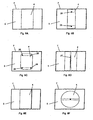
- FIGS. 6A to 6F are various ways to connect a material layer with a vacuum cleaner filter bag, illustrated schematically. Shown is in each case the plan view of an inner side of the bag 5. It is the inside of the bag facing a rectangular filter material layer for a flat bag, said filter material layer is opposite to the inlet opening of the bag in prefabricated vacuum cleaner filter bag. This filter material layer is, for example, welded to the opposite filter material layer in which the inlet opening is located along the side edges, so that a seam 7 is formed on each edge.
- a material layer 4 in the form of a rectangular strip is arranged centrally on the inside of the bag 5.
- the material layer has an area of about one third of the area of the associated filter material layer (bag wall) and thus an area of about one sixth of the inside of the entire vacuum cleaner filter bag.
- the material layer is connected to only two seams of the filter bag, in the view shown above and below, with the vacuum cleaner filter bag. This can be achieved, for example, by placing the material layer 4 in the manufacture of the vacuum cleaner filter bag between the two filter material layers and, during welding of the two filter material layers along the side edges, likewise being welded thereto. The material layer is thus connected in this way via two continuous welds with the vacuum cleaner filter bag.
- the other two side edges are unconnected to the filter material layer, so that an air stream entering the vacuum cleaner filter bag is located between the material layer 4 and the inlet opening Bag inside 5 of the filter material layer can flow.
- the material layer is raised during operation of the vacuum cleaner or removed from the filter material layer and set in motion.
- the air flow can flow from below through the material layer in the direction of the interior of the vacuum cleaner filter bag. It has surprisingly been found that this leads to a significantly better service life and dust storage capacity of the bag over a longer period of time, as described below with reference to the FIGS. 8 to 13 is explained in more detail.
- connection of the material layer with the vacuum cleaner filter bag By the in FIG. 6A shown connection of the material layer with the vacuum cleaner filter bag, the surface of the material layer on the associated filter material layer side facing an unconnected part, which is shown by dashed lines.
- This part includes the left and right side edges of the material layer except for their corners and forms a convex amount in the form of a rectangle. This convex amount makes up almost the entire area (except for the weld at the top and bottom edges) of the surface of the material layer.
- the material layer 4 connected only at two points 26 with the bag inner side 5. These points may, for example, be spot welds or glue dots.
- the material strip is also arranged centrally, but does not extend in the longitudinal direction up to the hems 7 of the vacuum cleaner bag.
- a convex amount which is formed by an unconnected part of the surface of the material layer and lies between the two connection points, is also drawn in a dashed line.
- the unconnected part closes both the vertical projection of the center (geometric center of gravity) of the material layer on its surface facing away from the inlet opening and a distance leading through this projection point, which extends from the left to the right edge of the material layer. In this way, an air flow can flow under the material layer.
- the material strip 4 in FIG. 6C has rounded corners and is connected at four points 26 to the bag inner side 5 of the vacuum cleaner filter bag.
- the material layer 4 is given in the form of a rectangular strip. This strip of material is connected via a single weld 27 with the inside 5 of the vacuum cleaner filter bag. This weld 27 runs parallel to the left and right Side edge and through the center of the material layer. Two convex sets, each formed by an unconnected part, are indicated by dashed lines.
- FIG. 6E is the strip of material 4 as in FIG. 6A connected at two seams with the vacuum cleaner filter bag. Furthermore, an additional weld 27 is provided on the right side edge of the material layer 4. Thus, an air flow can flow only from the left side under the material layer.
- FIG. 6F shows a circular layer of material, which is arranged centrally on the filter material layer of the Staubaugerfilter milks. This material layer is connected to the inner side of the bag at a single point 26, which is arranged in the middle of the material layer 4.
- two unconnected parts each form a convex amount in the form of a circle segment.
- the material layer 4 completely covers the filter material layer opposite the inlet opening and is connected to the seams 7 with the latter.
- the material layer has three slots 28 through which an air flow can flow under the material layer.
- a convex surface between two slits is indicated by dashed lines
- the material layer again has a smaller area than the area of the bag wall connected therewith to the hems.
- four slots 28 are provided perpendicular to the open side edges of the material layer, in order to further promote an underflow of the material layer.
- the shape, the extent and the arrangement of the material layer can be modified.
- the material layer can also be otherwise connected, for example via a plurality of welding points, with the filter material layer on the inside of the bag.
- two or more layers of material may be provided, for example, two superimposed rectangular strips, as shown in FIG. 6A connected to the hem with the vacuum cleaner filter bag.
- FIGS. 6A to 6H shown material layer of individual substantially (except via connections with the vacuum cleaner filter bag) with each other consist of unconnected fibers. These can be z. B. parallel or perpendicular to the longitudinal direction of the in the FIGS. 6a to 6e be aligned strip and connected at each end of the fibers in the fiber longitudinal direction with the bag inner side 5.
- the fibers may pass through a weld or adhesive seam along or oblique to the width of the in the FIGS. 6a to 6e strip shown with each other and be connected to the bag inside 5. That is, in an example where the strip shown is made up of fibers arranged parallel to the strip direction, the fibers may be attached to the bag inner side 5 after parallel alignment by welding or gluing perpendicular to the fiber longitudinal direction. All fibers can be attached to the in Fig. 6a shown upper seam 7 of the vacuum cleaner filter bag are attached simultaneously in one operation and fastened to the lower seam 7 at the same time in another operation. Except for these attachments to the hems, the fibers are not interconnected.
- FIG. 7 shows the top view of the inside 5 of a vacuum cleaner filter bag with a material layer 4 arranged thereon.
- the outlines of a collapsible deflector 2 are projected onto the surface of the material layer and the filter material layer.
- the deflection device comprises two outlet openings, each occupy an entire side surface of the cuboid shape, as soon as the vacuum cleaner filter bag is in operation.
- the outflow directions are indicated by two arrows.
- the deflecting device shown thus corresponds to the in FIG. 2 shown embodiment.
- each fold line 10 with a (in the view shown perpendicular) edge or a side edge of the material layer, which is enclosed by the unconnected part and thus not connected to the bag inner side, an angle ⁇ .
- This angle ⁇ is preferably at least 15 °. This makes it possible for a stream of air flowing out of the deflection device during operation of the vacuum cleaner filter bag to flow into the vacuum cleaner filter bag in such a manner that it can advantageously flow below the material layer 4.
- An angle ⁇ 90 ° is particularly preferred in which the discharge directions are in the case of the deflection device shown stand perpendicular to the side edges of the material layer.
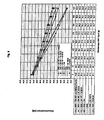
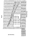
- FIGS. 8 to 10 illustrate the surprising improvement of conventional vacuum cleaner filter bags through the use of a deflector and a sheet of material as previously described.
- dust dusting tests were carried out with various vacuum cleaner filter bags, in which defined amounts of dust were sucked into the dust filter bag and the remaining volume flow was measured.
- the vacuum cleaner used was a Miele S 5220, whose performance was set to maximum.
- the size of the flat bag was 317 x 330 mm.
- the material layer in the form of a rectangular strip connected to the inside of the bag of the filter material layer of a filter bag had a width of 130 mm.
- the deflector had the shape of a cuboid as in FIG. 3 shown and was analogous to FIG. 2 connected to the filter material of the vacuum cleaner filter bag.
- the material of the deflector was cardboard; the dimensions were 80 mm x 80 mm x 30 mm (length x width x height).
- the vacuum cleaner filter bag to be tested was installed in the apparatus after the vacuum cleaner had warmed up for 10 minutes.
- the volume flow without dust load was read after 1 minute of running time of the device. Subsequently, the first 50 g portion of dust was sucked in within 30 seconds. After 1 minute, the self-adjusting volume flow (in m 3 / h) was read. This step was repeated for the following dust additions until 400 grams of dust had been added.
- vacuum cleaner filter bags were compared to neither a deflection device nor a material layer which has a deflection device or a material layer, as well as a deflection device and a material layer.
- volumetric flow readings (in l / s) are plotted against the amount of dust sucked in. Furthermore, below each graph is a table with the exact values of the respective measurement results at 0g, 50g, 100g, ..., 400g amount of dust.
- the filter media used were obtained from Airflo Europe N.V., Overpelt, Belgium.
- the terms in the graphics have the following meaning.
- the first abbreviation designates the filter material of the vacuum cleaner filter bag, ie the filter material layers from which the flat bag was made.
- SMS refers to a composite nonwoven fabric (composite) in the air flow direction, ie from the inside of the bag to the outside - a spunbond (17 g / m 2 basis weight), a fine fiber fleece (meltblown) (24 g / m 2 ) and a spunbonded nonwoven ( 25 g / m 2 ).
- 75CS is a composite nonwoven fabric consisting of - in the air flow direction - a spunbonded nonwoven (17 g / m 2 ), a drained nonwoven of electrostatically charged split fibers (75 g / m 2 ), a fine fiber nonwoven (24 g / m 2 ) and a spunbonded nonwoven (25 g / m 2 ).
- the abbreviation "30K” indicates the presence of a deflector; if additionally an angle is indicated, then this is the angle ⁇ in FIG. 7 between the side edge of the deflector (perpendicular to the plane of the exit opening) and the unconnected side edge of the sheet of material.
- “St” indicates that a material layer was connected to the inside of the filter material layer.
- the following abbreviation (“130CS” or 60SB ”) explains what the material layer consisted of.”
- 130CS refers to a composite nonwoven fabric of a spunbonded fabric (17 g / m 2 ), a drained nonwoven fabric of electrostatically charged split fibers (130 g / m 2 ), a fine fiber fleece (24 g / m 2 ) and a spunbonded nonwoven (25 g / m 2 ).
- “60SB” is a spunbond with a basis weight of 60 g / m 2.
- SMS + 30K 90 ° + St 130CS a filter bag made of SMS material (as described above) comprising a deflector, whose fold lines are oriented perpendicular to the unconnected side edge of the material layer, and a material layer of 130CS material examined.
- FIG. 8 one recognizes first that a filter bag only with a material layer but without deflection device ("SMS + 130CS ''and” SMS + 60SB ”) has a deterioration in performance compared to a bag without material layer and without deflector (“ SMS ”) has the consequence
- SMS deflector
- the combination of a deflector with a layer of material leads to a significant improvement with both a 60SB strip and a 130CS strip FIG. 6B with two points again an increase in performance.
- FIG. 9 It can be seen that even with a filter material of the bag with a high dust holding capacity ("75CS", especially due to the drained nonwoven fabric), the combination of a deflector and a loose strip of material according to FIG. 6A a significant improvement in performance.
- 75CS high dust holding capacity
- FIG. 10 the influence of the arrangement of the deflector with respect to the loose strip of material is shown.
- the specified angle corresponds to the angle ⁇ in FIG. 7 ,
Landscapes
- Engineering & Computer Science (AREA)
- Mechanical Engineering (AREA)
- Filters For Electric Vacuum Cleaners (AREA)
- Filtering Materials (AREA)
- Filtering Of Dispersed Particles In Gases (AREA)
Claims (66)
- Sac filtrant d'aspirateur (1) avec une ouverture d'entrée (3), avec une couche de matériau perméable à l'air (4), qui est disposée à l'intérieur du sac filtrant d'aspirateur et qui est reliée au sac filtrant d'aspirateur à au moins un endroit,
caractérisé en ce que
la couche de matériau perméable à l'air présente au moins une partie, qui est non reliée au sac filtrant d'aspirateur et comprend une partie du bord de la couche de matériau, et
le sac filtrant d'aspirateur comprend un dispositif de déviation (2), qui est disposé à l'intérieur du sac filtrant d'aspirateur dans la zone de l'ouverture d'entrée et qui est conçu de façon à ce qu'un flux d'air entrant par l'ouverture d'entrée puisse être dévié par le dispositif de déviation. - Sac filtrant d'aspirateur selon la revendication 1, dans lequel la couche de matériau présente une surface inférieure sur la surface du côté intérieur du sac filtrant d'aspirateur.
- Sac filtrant d'aspirateur selon la revendication 1 ou 2, dans lequel la surface d'au moins une partie représente au moins 20 % de la surface de la couche de matériau.
- Sac filtrant d'aspirateur selon l'une quelconque des revendications précédentes, dans lequel est formée un ensemble convexe au moyen d'au moins une partie sur une surface de la couche de matériau.
- Sac filtrant d'aspirateur selon l'une quelconque des revendications précédentes, dans lequel au moins une partie comprend le point de projection, qui résulte d'une projection perpendiculaire du centre de gravité géométrique de la couche de matériau à la surface d'un côté de la couche de matériau.
- Sac filtrant d'aspirateur selon la revendication 4, dans lequel au moins une partie comprend un espace sur la surface conduisant à travers le point de projection, dont les points terminaux touchent respectivement le bord de la couche de matériau.
- Sac filtrant d'aspirateur selon l'une quelconque des revendications précédentes, dans lequel au moins une partie comprend au moins 10 % du bord de la couche de matériau.
- Sac filtrant d'aspirateur selon l'une quelconque des revendications précédentes, dans lequel la couche de matériau présente une forme polygonale, en particulier carrée, et une partie au moins comprend une partie d'au moins deux arêtes latérales, en particulier situées l'une en face de l'autre, de la couche de matériau.
- Sac filtrant d'aspirateur selon l'une quelconque des revendications précédentes, dans lequel la couche de matériau est reliée au sac filtrant d'aspirateur par une quantité prédéterminée de points, de préférence par exactement deux points, et/ou par deux lisières du sac filtrant d'aspirateur.
- Sac filtrant d'aspirateur selon l'une quelconque des revendications précédentes, dans lequel la couche de matériau présente une forme rectangulaire et est reliée au sac filtrant d'aspirateur seulement le long de deux arêtes latérales, en particulier situées l'une en face de l'autre, en particulier des côtés courts.
- Sac filtrant d'aspirateur selon l'une quelconque des revendications précédentes, dans lequel la couche de matériau comprend un non-tissé, en particulier comprenant une couche absorbante, un filé-lié, un non-tissé humide et/ou un non-tissé sec, un papier ou un film perméable à l'air.
- Sac filtrant d'aspirateur selon l'une quelconque des revendications précédentes, dans lequel la couche de matériau a de préférence une surface de 10 à 80 %, de préférence de 15 à 30 % de la surface du côté intérieur du sac filtrant d'aspirateur.
- Sac filtrant d'aspirateur selon l'une quelconque des revendications précédentes, dans lequel la couche de matériau est reliée au sac filtrant d'aspirateur en face de l'ouverture d'entrée du sac filtrant d'aspirateur.
- Sac filtrant d'aspirateur selon l'une quelconque des revendications précédentes, dans lequel au moins une partie présente au moins une fente.
- Sac filtrant d'aspirateur selon l'une quelconque des revendications précédentes, dans lequel le sac filtrant d'aspirateur est conçu comme sac plat avec deux couches rectangulaires de matériau filtrant, reliées l'une à l'autre le long du bord et la couche de matériau est reliée à la couche de matériau filtrant située en face de l'ouverture d'entrée du sac filtrant d'aspirateur, en particulier au milieu et présente une forme rectangulaire avec une largeur de 10 à 80 %, de préférence de 25 à 40 %, de la largeur de la couche de matériau filtrant qui y est reliée et/ou d'une longueur de 60 à 100 %, de préférence 100 % de la longueur de la couche de matériau filtrant du sac filtrant d'aspirateur, qui y est reliée.
- Sac filtrant d'aspirateur selon l'une quelconque des revendications précédentes, dans lequel la couche de matériau comprend un laminé, en particulier un SMS.
- Sac filtrant d'aspirateur selon l'une quelconque des revendications précédentes, dans lequel la couche de matériau comprend différentes fibres non reliées les unes aux autres ou un réseau de fibres en feuille.
- Sac filtrant d'aspirateur selon la revendication 17, dans lequel les directions des axes longitudinaux des différentes fibres non reliées les unes aux autres enferment un angle de moins de 45° les unes par rapport aux autres.
- Sac filtrant d'aspirateur selon la revendication 17 ou 18, dans lequel au moins une partie des différentes fibres est disposée de manière juxtaposée avec ou sans écart les unes par rapport aux autres ou se chevauchant les unes sur les autres.
- Sac filtrant d'aspirateur selon l'une quelconque des revendications 17 à 19, dans lequel au moins une partie des fibres est reliée au sac filtrant d'aspirateur aux deux extrémités des fibres dans la direction longitudinale des fibres.
- Sac filtrant d'aspirateur selon l'une quelconque des revendications 17 à 20, dans lequel au moins une partie des fibres est reliée au sac filtrant d'aspirateur par une ou plusieurs liaisons linéaires ou superficielles.
- Sac filtrant d'aspirateur selon l'une quelconque des revendications 17 à 21, dans lequel la couche de matériau se compose de différentes fibres non reliées les unes aux autres.
- Sac filtrant d'aspirateur selon l'une quelconque des revendications précédentes, comprenant en outre une couche de matériau supplémentaire perméable à l'air, qui est disposée à l'intérieur du sac filtrant d'aspirateur, qui est reliée à au moins un endroit au sac filtrant d'aspirateur et/ou à l'autre couche de matériau perméable à l'air, et qui présente au moins une partie, qui n'est pas reliée au sac filtrant d'aspirateur et/ou à l'autre couche de matériau perméable à l'air et qui comprend une partie du bord de la couche de matériau.
- Sac filtrant d'aspirateur selon l'une quelconque des revendications précédentes, dans lequel le dispositif de déviation entoure au moins partiellement l'ouverture d'entrée du sac filtrant d'aspirateur et est fixé au côté intérieur du sac.
- Sac filtrant d'aspirateur selon l'une quelconque des revendications précédentes, dans lequel le dispositif de déviation est conçu pour répartir le flux d'air en au moins deux flux partiels.
- Sac filtrant d'aspirateur selon l'une quelconque des revendications précédentes, dans lequel le dispositif de déviation pour répartir le flux d'air dans au moins deux flux partiels est conçu avec des directions d'écoulement opposées l'une à l'autre.
- Sac filtrant d'aspirateur selon l'une quelconque des revendications précédentes, dans lequel le dispositif de déviation comprend au moins une surface de déviation, de préférence plane, située en face de l'ouverture d'entrée.
- Sac filtrant d'aspirateur selon la revendication 27, dans lequel au moins une surface de déviation présente une surface de grandeur équivalente ou supérieure à la surface de l'ouverture d'entrée.
- Sac filtrant d'aspirateur selon la revendication 27 ou 28, dans lequel au moins une surface de déviation est disposée dans un angle prédéterminé par rapport au plan de l'ouverture d'entrée.
- Sac filtrant d'aspirateur selon l'une quelconque des revendications précédentes, dans lequel le dispositif de déviation comprend la forme d'un cylindre, d'un cône tronqué, d'un parallélépipède rectangle ou d'une pyramide tronquée, qui présente, dans la surface de couverture, une ouverture d'entrée et dans la paroi latérale au moins une ouverture de sortie.
- Sac filtrant d'aspirateur selon l'une quelconque des revendications précédentes, dans lequel le dispositif de déviation est conçu de façon à ce qu'il présente dans une première position, une extension réduite en comparaison d'une seconde position, perpendiculairement au plan de l'ouverture d'entrée.
- Sac filtrant d'aspirateur selon la revendication 31, dans lequel le dispositif de déviation est conçu de façon à ce qu'il puisse être amené par un flux d'air aspirant de la première position dans la seconde position.
- Sac filtrant d'aspirateur selon la revendication 31 ou 32, dans lequel le dispositif de déviation comprend un élément à ressort, qui exerce sur une partie du dispositif de déviation une force de retour de façon à ce que le dispositif de déviation puisse être amené de la seconde position dans la première position en fonction d'un flux d'air aspirant.
- Sac filtrant d'aspirateur selon l'une quelconque des revendications 31 à 33, dans lequel le dispositif de déviation comprend des lignes de plis, de telle sorte que le dispositif de déviation peut être amené de la première position dans la seconde position et inversement.
- Sac filtrant d'aspirateur selon la revendication 34, dans lequel
le dispositif de déviation présente la forme d'un parallélépipède rectangle, qui présente dans la surface de couverture entourant l'ouverture d'entrée, une ouverture d'écoulement et dans une surface latérale, une ouverture d'évacuation, dans lequel l'ouverture d'évacuation loge toute la surface latérale et les lignes de plis sur les arêtes latérales sont prévues perpendiculairement à la surface latérale de l'ouverture d'évacuation,
le sac filtrant d'aspirateur est conçu comme sac plat,
la couche de matériau présente une forme carrée et est reliée en face de l'ouverture d'entrée au sac filtrant d'aspirateur, et
le dispositif de déviation est disposé de façon à ce qu'une des lignes de pli comprenne un angle d'au moins 15°, à l'état plat du sac filtrant d'aspirateur avec un bord, qui est compris dans la partie non reliée. - Sac filtrant d'aspirateur selon l'une quelconque des revendications précédentes, dans lequel le dispositif de déviation comprend un matériau sensiblement imperméable à l'air, en particulier une matière plastique, un non-tissé sec ou humide ou du papier, en particulier du carton, ou un film.
- Utilisation d'un sac filtrant d'aspirateur avec une couche de matériau perméable à l'air dans un aspirateur avec un dispositif de déviation, qui est conçu comme partie d'un support pour un aspirateur, qui en outre comprend un dispositif d'assemblage pour assembler le dispositif de déviation à un support de raccordement, qui relie à son tour le sac filtrant d'aspirateur à un tuyau d'aspiration de l'aspirateur,
selon laquelle le dispositif d'assemblage et le dispositif de déviation sont conçus de façon à ce que le dispositif de déviation, pendant le fonctionnement de l'aspirateur, soit disposé à l'intérieur du sac filtrant d'aspirateur et qu'un flux d'air entrant dans le dispositif d'assemblage soit dévié dans le dispositif de déviation, et
selon laquelle la couche de matériau est disposée à l'intérieur du sac filtrant d'aspirateur et présente au moins une partie, qui n'est pas reliée au sac filtrant d'aspirateur et qui comprend une partie du bord de la couche de matériau. - Utilisation selon la revendication 37, selon laquelle la couche de matériau présente une surface inférieure à la surface du côté intérieur du sac filtrant d'aspirateur.
- Utilisation selon la revendication 37 ou 38, selon laquelle la surface d'au moins une partie représente au moins 20 % de la surface de la couche de matériau.
- Utilisation selon l'une quelconque des revendications 37 à 39, selon laquelle un ensemble convexe est constitué au moyen de la partie non reliée à une surface de la couche de matériau.
- Utilisation selon l'une quelconque des revendications 37 à 40, selon laquelle au moins une partie comprend le point de projection, qui résulte d'une projection perpendiculaire du centre de gravité géométrique de la couche de matériau à la surface d'un côté de la couche de matériau.
- Utilisation selon la revendication 41, selon laquelle au moins une partie comprend un espace conduisant sur la surface à travers le point de projection, dont les points terminaux touchent respectivement le bord de la couche de matériau.
- Utilisation selon l'une quelconque des revendications 37 à 42, selon laquelle au moins une partie inclut au moins 10 % du bord de la couche de matériau.
- Utilisation selon l'une quelconque des revendications 37 à 43, selon laquelle la couche de matériau présente une forme polygonale, en particulier carrée, et qu'au moins une partie comprend une partie d'au moins deux arêtes latérales, en particulier situées l'une en face de l'autre, de la couche de matériau.
- Utilisation selon l'une quelconque des revendications 37 à 44, selon laquelle la couche de matériau est reliée au sac filtrant d'aspirateur par une quantité prédéterminée de points, de préférence par exactement deux points, et/ou par deux lisières du sac filtrant d'aspirateur.
- Utilisation selon l'une quelconque des revendications 37 à 45, selon laquelle la couche de matériau présente une forme rectangulaire et est reliée au sac filtrant d'aspirateur seulement le long de deux arêtes latérales, en particulier situées l'une en face de l'autre, en particulier les côtés courts.
- Utilisation selon l'une quelconque des revendications 37 à 46, selon laquelle le matériau de la couche de matériau comprend un papier, un non-tissé, en particulier comprenant une couche absorbante, un filé-lié, un non-tissé humide et/ou un non-tissé sec, ou un film perméable à l'air.
- Utilisation selon l'une quelconque des revendications 37 à 47, selon laquelle la couche de matériau a une surface de 10 à 80 %, de préférence de 15 à 30 % de la surface du côté intérieur du sac filtrant d'aspirateur qui y est reliée.
- Utilisation selon l'une quelconque des revendications 37 à 48, selon laquelle la couche de matériau est reliée au sac filtrant d'aspirateur en face de l'ouverture d'entrée du sac filtrant d'aspirateur.
- Utilisation selon l'une quelconque des revendications 37 à 49, selon laquelle au moins une partie présente au moins une fente.
- Utilisation selon l'une quelconque des revendications 37 à 50, selon laquelle le sac filtrant d'aspirateur est conçu comme sac plat avec deux couches rectangulaires de matériau filtrant, reliées l'une à l'autre le long du bord et la couche de matériau est reliée à la couche de matériau filtrant située en face de l'ouverture d'entrée du sac filtrant d'aspirateur, en particulier au milieu et présente une forme rectangulaire avec une largeur de 10 à 80 %, de préférence de 25 à 40 %, de la largeur de la couche de matériau filtrant qui y est reliée et/ou d'une longueur de 60 à 100 %, de préférence 100 % de la longueur de la couche de matériau filtrant du sac filtrant d'aspirateur, qui y est reliée.
- Utilisation selon l'une quelconque des revendications 37 à 51, selon laquelle la couche de matériau présente au moins un laminé, en particulier un SMS.
- Utilisation selon l'une quelconque des revendications 37 à 52, selon laquelle la couche de matériau présente différentes fibres non reliées entre elles ou un réseau de fibres en feuille.
- Utilisation selon la revendication 53, selon laquelle les directions des axes longitudinaux des différentes fibres non reliées entre elles enferment un angle de moins de 45° les unes par rapport aux autres.
- Utilisation selon la revendication 53 ou 54, selon laquelle au moins une partie des différentes fibres est disposée de manière juxtaposée avec ou sans écart les unes par rapport aux autres ou se chevauchant les unes sur les autres.
- Utilisation selon l'une quelconque des revendications 53 à 55, selon laquelle au moins une partie des fibres est reliée au sac filtrant d'aspirateur aux deux extrémités des fibres en direction longitudinale des fibres.
- Utilisation selon l'une quelconque des revendications 53 à 56, selon laquelle au moins une partie des fibres est reliée au sac filtrant d'aspirateur par une ou plusieurs liaisons linéaires ou superficielles.
- Utilisation selon l'une quelconque des revendications 53 à 57, selon laquelle la couche de matériau se compose de différentes fibres non reliées les unes aux autres.
- Utilisation selon l'une quelconque des revendications 37 à 58, comprenant en outre une couche de matériau supplémentaire perméable à l'air, qui est disposée à l'intérieur du sac filtrant d'aspirateur, qui est reliée à au moins un endroit au sac filtrant d'aspirateur et/ou à l'autre couche de matériau perméable à l'air, et qui présente au moins une partie, qui n'est pas reliée au sac filtrant d'aspirateur et/ou à l'autre couche de matériau perméable à l'air et qui inclut une partie du bord de la couche de matériau.
- Utilisation selon l'une quelconque des revendications 37 à 59, selon laquelle le dispositif de déviation est conçu pour répartir le flux d'air en au moins deux flux partiels.
- Utilisation selon l'une quelconque des revendications 37 à 60, selon laquelle le dispositif de déviation pour répartir le flux d'air en au moins deux flux partiels est conçu avec des directions d'écoulement opposées l'une à l'autre.
- Utilisation selon l'une quelconque des revendications 37 à 61, selon laquelle le dispositif de déviation comprend la forme d'un cylindre, d'un cône tronqué, d'un parallélépipède rectangle ou d'une pyramide tronquée, qui présente dans la surface de couverture, une ouverture d'entrée et dans la paroi latérale au moins une ouverture de sortie.
- Utilisation selon l'une quelconque des revendications 37 à 62, selon laquelle le dispositif de déviation comprend au moins une surface de déviation, de préférence plane, située en face de l'ouverture d'entrée.
- Utilisation selon la revendication 63, selon laquelle au moins une surface de déviation présente une surface équivalente ou supérieure à la surface de l'ouverture d'entrée.
- Utilisation selon la revendication 63 ou 64, selon laquelle au moins une surface de déviation est disposée dans un angle prédéterminé par rapport au plan de l'ouverture d'entrée.
- Utilisation selon l'une quelconque des revendications 63 à 65, selon laquelle le dispositif de déviation comprend un matériau sensiblement imperméable à l'air, en particulier une matière plastique, un non-tissé sec ou humide ou du papier, en particulier du carton, ou un film.
Priority Applications (3)
| Application Number | Priority Date | Filing Date | Title |
|---|---|---|---|
| ES06818737T ES2306436T5 (es) | 2005-11-22 | 2006-11-22 | Bolsa filtrante de aspirador y uso de una bolsa filtrante de aspirador. |
| PL06818737T PL1804635T5 (pl) | 2005-11-22 | 2006-11-22 | Worek filtracyjny odkurzacza i zastosowanie worka filtracyjnego odkurzacza |
| EP06818737A EP1804635B2 (fr) | 2005-11-22 | 2006-11-22 | Sac filtrant d'aspirateur et utilisation d'un sac filtrant d'aspirateur |
Applications Claiming Priority (9)
| Application Number | Priority Date | Filing Date | Title |
|---|---|---|---|
| EP05025480 | 2005-11-22 | ||
| EP05025904 | 2005-11-28 | ||
| EP05027013A EP1787560B1 (fr) | 2005-11-22 | 2005-12-09 | Sac à poussières d'aspirateur avec dispositif de déviation |
| EP05027219.4A EP1787561B1 (fr) | 2005-11-22 | 2005-12-13 | Sac à poussières d'aspirateur comprenant un dispositif de fermeture |
| EP06003723.1A EP1787562B1 (fr) | 2005-11-22 | 2006-02-23 | Raccord avec dispositif de déviation pour un aspirateur |
| EP06004980A EP1787563A1 (fr) | 2005-11-22 | 2006-03-10 | Sac filtrant d'un aspirateur et son utilisation |
| DE200610016009 DE102006016009A1 (de) | 2006-04-05 | 2006-04-05 | Staubsaugerfilterbeutel und Verwendung eines Staubsaugerfilterbeutels |
| EP06818737A EP1804635B2 (fr) | 2005-11-22 | 2006-11-22 | Sac filtrant d'aspirateur et utilisation d'un sac filtrant d'aspirateur |
| PCT/EP2006/011191 WO2007059939A1 (fr) | 2005-11-22 | 2006-11-22 | Sac filtrant d'aspirateur et utilisation d'un sac filtrant d'aspirateur |
Publications (3)
| Publication Number | Publication Date |
|---|---|
| EP1804635A1 EP1804635A1 (fr) | 2007-07-11 |
| EP1804635B1 true EP1804635B1 (fr) | 2008-05-21 |
| EP1804635B2 EP1804635B2 (fr) | 2011-02-16 |
Family
ID=37719282
Family Applications (1)
| Application Number | Title | Priority Date | Filing Date |
|---|---|---|---|
| EP06818737A Active EP1804635B2 (fr) | 2005-11-22 | 2006-11-22 | Sac filtrant d'aspirateur et utilisation d'un sac filtrant d'aspirateur |
Country Status (6)
| Country | Link |
|---|---|
| EP (1) | EP1804635B2 (fr) |
| AT (1) | ATE395858T1 (fr) |
| DE (2) | DE502006000799D1 (fr) |
| ES (1) | ES2306436T5 (fr) |
| PL (1) | PL1804635T5 (fr) |
| WO (1) | WO2007059939A1 (fr) |
Cited By (1)
| Publication number | Priority date | Publication date | Assignee | Title |
|---|---|---|---|---|
| DE202009002970U1 (de) | 2008-07-02 | 2009-11-19 | Branofilter Gmbh | Staubfilterbeutel mit Pralleinrichtung |
Families Citing this family (29)
| Publication number | Priority date | Publication date | Assignee | Title |
|---|---|---|---|---|
| DE202008003248U1 (de) | 2008-03-07 | 2008-05-08 | Eurofilters Holding N.V. | Staubsaugerfilterbeutel |
| EP2098151B1 (fr) * | 2008-03-07 | 2013-10-23 | Eurofilters Holding N.V. | Sac d'aspirateur |
| ES2549756T3 (es) | 2009-06-19 | 2015-11-02 | Eurofilters N.V. | Bolsa plana para aspirador de polvo con al menos dos difusores |
| DE202009019156U1 (de) | 2009-06-19 | 2017-04-20 | Eurofilters N.V. | Flachbeutel für Staubsauger |
| EP3443880B1 (fr) | 2009-06-19 | 2021-05-12 | Eurofilters N.V. | Sachet plat pour aspirateur |
| EP2266450B1 (fr) | 2009-06-24 | 2016-09-21 | Eurofilters N.V. | Filtre sac à fond plat pour aspirateurs |
| DK2662010T3 (da) | 2010-03-19 | 2014-10-06 | Eurofilters Holding Nv | Støvsugerfilterpose |
| DE202011000339U1 (de) * | 2011-02-15 | 2011-04-14 | Wolf Pvg Gmbh & Co. Kg | Staubsaugerbeutel |
| ES2713045T3 (es) | 2011-03-22 | 2019-05-17 | Eurofilters Nv | Dispositivo ecológicamente eficiente para la aspiración de polvo |
| DE102011014682A1 (de) | 2011-03-22 | 2012-09-27 | Eurofilters Holding N.V. | Vorrichtung zum Staubsaugen mit Staubsaugergerät und Filterbeutel |
| DE202011108953U1 (de) | 2011-12-02 | 2012-01-19 | Branofilter Gmbh | Staubfilterbeutel mit einer Staubfängereinlage |
| DE102011120688B4 (de) | 2011-12-02 | 2019-05-16 | Branofilter Gmbh | Staubfilterbeutel mit einer Staubfängereinlage |
| EP3072430B1 (fr) | 2012-03-22 | 2017-05-10 | Eurofilters Holding N.V. | Dispositif destiné à aspirer à l'aide d'un aspirateur et d'un sac filtrant |
| CN104116462B (zh) * | 2013-04-26 | 2017-06-30 | 天佑电器(苏州)有限公司 | 过滤袋及具有该过滤袋的吸尘器 |
| EP2926705A1 (fr) | 2014-04-04 | 2015-10-07 | Eurofilters Holding N.V. | Dispositif destiné à aspirer à l'aide d'un aspirateur de chaudière |
| EP2926706A1 (fr) | 2014-04-04 | 2015-10-07 | Eurofilters Holding N.V. | Dispositif d'aspiration de poussière |
| ES2625427T3 (es) | 2014-04-08 | 2017-07-19 | Eurofilters N.V. | Bolsa de filtro para aspiradores de polvo para un aspirador de polvo vertical |
| EP3305155B1 (fr) | 2016-10-06 | 2019-05-22 | Eurofilters N.V. | Sac d'aspirateur en matériaux textiles recyclés et/ou de linters de coton |
| PL3219237T3 (pl) | 2016-03-17 | 2018-10-31 | Eurofilters Holding N.V. | Płytka mocująca z udoskonalonym elementem zamykającym |
| DK3219376T3 (en) | 2016-03-17 | 2019-01-14 | Eurofilters Nv | Vacuum cleaner filter bag of recycled plastics |
| EP3219236B1 (fr) | 2016-03-17 | 2021-09-01 | Eurofilters Holding N.V. | Plaque de maintien dotee d'une fermeture amelioree |
| EP3219235B1 (fr) | 2016-03-17 | 2021-12-29 | Eurofilters Holding N.V. | Dispositif pour un sac filtrant d'aspirateur avec dispositif de maintien et dispositif de verrouillage |
| EP3219374B1 (fr) | 2016-03-17 | 2019-05-08 | Eurofilters N.V. | Sac d'aspirateur en materiaux synthetiques recycles |
| ES2793388T3 (es) | 2016-03-17 | 2020-11-13 | Eurofilters Nv | Bolsa filtrante para aspiradora de polvo, a base de materiales sintéticos reciclados |
| EP3219373B1 (fr) | 2016-03-17 | 2018-03-07 | Eurofilters N.V. | Sac d'aspirateur en materiaux textiles recycles et/ou de linters de coton |
| DE202016008752U1 (de) | 2016-10-06 | 2019-06-17 | Eurofilters N.V. | Staubsaugerfilterbeutel mit recycliertem Textilmaterialien und/oder Baumwolllinters |
| ES2894746T3 (es) | 2017-02-07 | 2022-02-15 | Eurofilters Holding Nv | Placa de sujeción para una bolsa de filtro de aspiradora con dispositivo de cierre |
| PL3669734T3 (pl) | 2018-12-17 | 2021-07-05 | Eurofilters Holding N.V. | Worek filtracyjny do odkurzacza mający spoinę zgrzewaną o ulepszonej wytrzymałości |
| EP3950087A1 (fr) | 2020-08-06 | 2022-02-09 | Eurofilters N.V. | Sac d'aspirateur en matières synthétiques recyclées |
Family Cites Families (11)
| Publication number | Priority date | Publication date | Assignee | Title |
|---|---|---|---|---|
| BE529649A (fr) † | ||||
| US2068332A (en) * | 1936-06-24 | 1937-01-19 | American Floor Surfacing Mach | Method and means of collecting dust from an air current |
| GB766086A (en) † | 1954-04-22 | 1957-01-16 | Lewyt Corp | Improvements in or relating to vacuum cleaners |
| FR1148583A (fr) † | 1956-02-23 | 1957-12-11 | Tornado A G | Collecteur de poussières pour aspirateur et aspirateur muni de ce dispositif |
| US3370405A (en) † | 1964-12-18 | 1968-02-27 | Studley Paper Company Inc | Vacuum cleaner filter bags and method of manufacturing same |
| DE1703030A1 (de) * | 1966-08-10 | 1972-01-27 | Eck B | Staubsauger |
| US5603741A (en) † | 1994-05-09 | 1997-02-18 | Hmi Industries, Inc. | Vacuum cleaner and filter bag with air management |
| DE19948909A1 (de) † | 1999-10-11 | 2001-04-12 | Vorwerk Co Interholding | Filterbeutel für einen Staubsauger |
| DE20010049U1 (de) † | 2000-06-03 | 2000-09-14 | Aichner Filter Gmbh | Staubfilterbeutel, insbesondere für einen Staubsauger |
| EP1415699B8 (fr) * | 2002-12-06 | 2004-07-28 | Eurofilters N.V. | Matériau de filtrage pour sac à poussières d'un aspirateur |
| DE202005009452U1 (de) † | 2005-06-15 | 2005-08-25 | Melitta Haushaltsprodukte Gmbh & Co. Kg | Staubsaugerbeutel und Kissen für einen Staubsaugerbeutel |
-
2006
- 2006-11-22 AT AT06818737T patent/ATE395858T1/de not_active IP Right Cessation
- 2006-11-22 DE DE502006000799T patent/DE502006000799D1/de active Active
- 2006-11-22 ES ES06818737T patent/ES2306436T5/es active Active
- 2006-11-22 EP EP06818737A patent/EP1804635B2/fr active Active
- 2006-11-22 WO PCT/EP2006/011191 patent/WO2007059939A1/fr active Application Filing
- 2006-11-22 DE DE202006020047U patent/DE202006020047U1/de not_active Expired - Lifetime
- 2006-11-22 PL PL06818737T patent/PL1804635T5/pl unknown
Cited By (1)
| Publication number | Priority date | Publication date | Assignee | Title |
|---|---|---|---|---|
| DE202009002970U1 (de) | 2008-07-02 | 2009-11-19 | Branofilter Gmbh | Staubfilterbeutel mit Pralleinrichtung |
Also Published As
| Publication number | Publication date |
|---|---|
| WO2007059939A1 (fr) | 2007-05-31 |
| DE202006020047U1 (de) | 2007-09-20 |
| PL1804635T5 (pl) | 2011-04-29 |
| ES2306436T3 (es) | 2008-11-01 |
| ES2306436T5 (es) | 2011-05-10 |
| EP1804635B2 (fr) | 2011-02-16 |
| ATE395858T1 (de) | 2008-06-15 |
| EP1804635A1 (fr) | 2007-07-11 |
| PL1804635T3 (pl) | 2008-10-31 |
| DE502006000799D1 (de) | 2008-07-03 |
Similar Documents
| Publication | Publication Date | Title |
|---|---|---|
| EP1804635B1 (fr) | Sac filtrant d'aspirateur et utilisation d'un sac filtrant d'aspirateur | |
| EP2098151B1 (fr) | Sac d'aspirateur | |
| EP1958561B1 (fr) | Sac d'aspirateur | |
| DE202008003248U1 (de) | Staubsaugerfilterbeutel | |
| EP2366320B2 (fr) | Sac d'aspirateur | |
| EP3443880B1 (fr) | Sachet plat pour aspirateur | |
| DE202010018516U1 (de) | Flachbeutel für Staubsauger | |
| EP2428151B1 (fr) | Dispositif destiné à aspirer à l'aide d'un appareil d'aspiration et d'un sac filtrant | |
| WO2007059936A1 (fr) | Sac d'aspirateur filtrant comportant un dispositif de deviation | |
| EP2452603B1 (fr) | Sachet de filtre d'aspirateur plié | |
| EP1787563A1 (fr) | Sac filtrant d'un aspirateur et son utilisation | |
| DE102006016009A1 (de) | Staubsaugerfilterbeutel und Verwendung eines Staubsaugerfilterbeutels | |
| EP1787564B1 (fr) | Plaque de fixation avec dispositif de déviation pour un sac à poussières d'aspirateur | |
| WO2007059938A1 (fr) | Sac filtrant d'aspirateur comportant un dispositif de fermeture | |
| EP2502537B1 (fr) | Dispositif efficace au plan écologique destiné à l'aspiration | |
| WO2016116221A1 (fr) | Aspirateur pour sols | |
| EP3030334B1 (fr) | Sac filtrant pour un aspirateur ainsi que procédé pour déterminer une surface d'un sac d'aspirateur sur laquelle l'air afflue directement | |
| DE202009019156U1 (de) | Flachbeutel für Staubsauger |
Legal Events
| Date | Code | Title | Description |
|---|---|---|---|
| PUAI | Public reference made under article 153(3) epc to a published international application that has entered the european phase |
Free format text: ORIGINAL CODE: 0009012 |
|
| 17P | Request for examination filed |
Effective date: 20070403 |
|
| AK | Designated contracting states |
Kind code of ref document: A1 Designated state(s): AT BE BG CH CY CZ DE DK EE ES FI FR GB GR HU IE IS IT LI LT LU LV MC NL PL PT RO SE SI SK TR |
|
| AX | Request for extension of the european patent |
Extension state: AL BA HR MK YU |
|
| GRAP | Despatch of communication of intention to grant a patent |
Free format text: ORIGINAL CODE: EPIDOSNIGR1 |
|
| DAX | Request for extension of the european patent (deleted) | ||
| GRAS | Grant fee paid |
Free format text: ORIGINAL CODE: EPIDOSNIGR3 |
|
| GRAA | (expected) grant |
Free format text: ORIGINAL CODE: 0009210 |
|
| AK | Designated contracting states |
Kind code of ref document: B1 Designated state(s): AT BE BG CH CY CZ DE DK EE ES FI FR GB GR HU IE IS IT LI LT LU LV MC NL PL PT RO SE SI SK TR |
|
| REG | Reference to a national code |
Ref country code: GB Ref legal event code: FG4D Free format text: NOT ENGLISH |
|
| REG | Reference to a national code |
Ref country code: CH Ref legal event code: EP |
|
| REF | Corresponds to: |
Ref document number: 502006000799 Country of ref document: DE Date of ref document: 20080703 Kind code of ref document: P |
|
| REG | Reference to a national code |
Ref country code: IE Ref legal event code: FG4D Free format text: LANGUAGE OF EP DOCUMENT: GERMAN |
|
| REG | Reference to a national code |
Ref country code: DK Ref legal event code: T3 |
|
| REG | Reference to a national code |
Ref country code: SE Ref legal event code: TRGR |
|
| PG25 | Lapsed in a contracting state [announced via postgrant information from national office to epo] |
Ref country code: SI Free format text: LAPSE BECAUSE OF FAILURE TO SUBMIT A TRANSLATION OF THE DESCRIPTION OR TO PAY THE FEE WITHIN THE PRESCRIBED TIME-LIMIT Effective date: 20080521 |
|
| PLBI | Opposition filed |
Free format text: ORIGINAL CODE: 0009260 |
|
| PG25 | Lapsed in a contracting state [announced via postgrant information from national office to epo] |
Ref country code: FI Free format text: LAPSE BECAUSE OF FAILURE TO SUBMIT A TRANSLATION OF THE DESCRIPTION OR TO PAY THE FEE WITHIN THE PRESCRIBED TIME-LIMIT Effective date: 20080521 |
|
| REG | Reference to a national code |
Ref country code: PL Ref legal event code: T3 |
|
| REG | Reference to a national code |
Ref country code: ES Ref legal event code: FG2A Ref document number: 2306436 Country of ref document: ES Kind code of ref document: T3 |
|
| 26 | Opposition filed |
Opponent name: WOLF PVG GMBH & CO. KOMMANDITGESELLSCHAFT Effective date: 20081009 |
|
| PG25 | Lapsed in a contracting state [announced via postgrant information from national office to epo] |
Ref country code: LV Free format text: LAPSE BECAUSE OF FAILURE TO SUBMIT A TRANSLATION OF THE DESCRIPTION OR TO PAY THE FEE WITHIN THE PRESCRIBED TIME-LIMIT Effective date: 20080521 |
|
| PG25 | Lapsed in a contracting state [announced via postgrant information from national office to epo] |
Ref country code: IS Free format text: LAPSE BECAUSE OF FAILURE TO SUBMIT A TRANSLATION OF THE DESCRIPTION OR TO PAY THE FEE WITHIN THE PRESCRIBED TIME-LIMIT Effective date: 20080921 |
|
| NLR1 | Nl: opposition has been filed with the epo |
Opponent name: WOLF PVG GMBH & CO. KOMMANDITGESELLSCHAFT |
|
| REG | Reference to a national code |
Ref country code: IE Ref legal event code: FD4D |
|
| PG25 | Lapsed in a contracting state [announced via postgrant information from national office to epo] |
Ref country code: IE Free format text: LAPSE BECAUSE OF FAILURE TO SUBMIT A TRANSLATION OF THE DESCRIPTION OR TO PAY THE FEE WITHIN THE PRESCRIBED TIME-LIMIT Effective date: 20080521 Ref country code: LT Free format text: LAPSE BECAUSE OF FAILURE TO SUBMIT A TRANSLATION OF THE DESCRIPTION OR TO PAY THE FEE WITHIN THE PRESCRIBED TIME-LIMIT Effective date: 20080521 Ref country code: CZ Free format text: LAPSE BECAUSE OF FAILURE TO SUBMIT A TRANSLATION OF THE DESCRIPTION OR TO PAY THE FEE WITHIN THE PRESCRIBED TIME-LIMIT Effective date: 20080521 |
|
| PLBI | Opposition filed |
Free format text: ORIGINAL CODE: 0009260 |
|
| PG25 | Lapsed in a contracting state [announced via postgrant information from national office to epo] |
Ref country code: SK Free format text: LAPSE BECAUSE OF FAILURE TO SUBMIT A TRANSLATION OF THE DESCRIPTION OR TO PAY THE FEE WITHIN THE PRESCRIBED TIME-LIMIT Effective date: 20080521 Ref country code: PT Free format text: LAPSE BECAUSE OF FAILURE TO SUBMIT A TRANSLATION OF THE DESCRIPTION OR TO PAY THE FEE WITHIN THE PRESCRIBED TIME-LIMIT Effective date: 20081021 Ref country code: RO Free format text: LAPSE BECAUSE OF FAILURE TO SUBMIT A TRANSLATION OF THE DESCRIPTION OR TO PAY THE FEE WITHIN THE PRESCRIBED TIME-LIMIT Effective date: 20080521 |
|
| PLAX | Notice of opposition and request to file observation + time limit sent |
Free format text: ORIGINAL CODE: EPIDOSNOBS2 |
|
| 26 | Opposition filed |
Opponent name: BRANOFILTER GMBH Effective date: 20090219 Opponent name: WOLF PVG GMBH & CO. KOMMANDITGESELLSCHAFT Effective date: 20081009 |
|
| PG25 | Lapsed in a contracting state [announced via postgrant information from national office to epo] |
Ref country code: BG Free format text: LAPSE BECAUSE OF FAILURE TO SUBMIT A TRANSLATION OF THE DESCRIPTION OR TO PAY THE FEE WITHIN THE PRESCRIBED TIME-LIMIT Effective date: 20080821 Ref country code: EE Free format text: LAPSE BECAUSE OF FAILURE TO SUBMIT A TRANSLATION OF THE DESCRIPTION OR TO PAY THE FEE WITHIN THE PRESCRIBED TIME-LIMIT Effective date: 20080521 |
|
| NLR1 | Nl: opposition has been filed with the epo |
Opponent name: BRANOFILTER GMBH Opponent name: WOLF PVG GMBH & CO. KOMMANDITGESELLSCHAFT |
|
| PG25 | Lapsed in a contracting state [announced via postgrant information from national office to epo] |
Ref country code: MC Free format text: LAPSE BECAUSE OF NON-PAYMENT OF DUE FEES Effective date: 20081130 |
|
| PLAF | Information modified related to communication of a notice of opposition and request to file observations + time limit |
Free format text: ORIGINAL CODE: EPIDOSCOBS2 |
|
| PLBB | Reply of patent proprietor to notice(s) of opposition received |
Free format text: ORIGINAL CODE: EPIDOSNOBS3 |
|
| PLAN | Information deleted related to communication of a notice of opposition and request to file observations + time limit |
Free format text: ORIGINAL CODE: EPIDOSDOBS2 |
|
| PLAS | Information related to reply of patent proprietor to notice(s) of opposition deleted |
Free format text: ORIGINAL CODE: EPIDOSDOBS3 |
|
| PLAX | Notice of opposition and request to file observation + time limit sent |
Free format text: ORIGINAL CODE: EPIDOSNOBS2 |
|
| PLBB | Reply of patent proprietor to notice(s) of opposition received |
Free format text: ORIGINAL CODE: EPIDOSNOBS3 |
|
| PG25 | Lapsed in a contracting state [announced via postgrant information from national office to epo] |
Ref country code: AT Free format text: LAPSE BECAUSE OF NON-PAYMENT OF DUE FEES Effective date: 20081122 |
|
| PG25 | Lapsed in a contracting state [announced via postgrant information from national office to epo] |
Ref country code: HU Free format text: LAPSE BECAUSE OF FAILURE TO SUBMIT A TRANSLATION OF THE DESCRIPTION OR TO PAY THE FEE WITHIN THE PRESCRIBED TIME-LIMIT Effective date: 20081122 Ref country code: LU Free format text: LAPSE BECAUSE OF NON-PAYMENT OF DUE FEES Effective date: 20081122 Ref country code: CY Free format text: LAPSE BECAUSE OF FAILURE TO SUBMIT A TRANSLATION OF THE DESCRIPTION OR TO PAY THE FEE WITHIN THE PRESCRIBED TIME-LIMIT Effective date: 20080521 |
|
| PG25 | Lapsed in a contracting state [announced via postgrant information from national office to epo] |
Ref country code: TR Free format text: LAPSE BECAUSE OF FAILURE TO SUBMIT A TRANSLATION OF THE DESCRIPTION OR TO PAY THE FEE WITHIN THE PRESCRIBED TIME-LIMIT Effective date: 20080521 |
|
| PG25 | Lapsed in a contracting state [announced via postgrant information from national office to epo] |
Ref country code: GR Free format text: LAPSE BECAUSE OF FAILURE TO SUBMIT A TRANSLATION OF THE DESCRIPTION OR TO PAY THE FEE WITHIN THE PRESCRIBED TIME-LIMIT Effective date: 20080822 |
|
| PUAH | Patent maintained in amended form |
Free format text: ORIGINAL CODE: 0009272 |
|
| STAA | Information on the status of an ep patent application or granted ep patent |
Free format text: STATUS: PATENT MAINTAINED AS AMENDED |
|
| 27A | Patent maintained in amended form |
Effective date: 20110216 |
|
| AK | Designated contracting states |
Kind code of ref document: B2 Designated state(s): AT BE BG CH CY CZ DE DK EE ES FI FR GB GR HU IE IS IT LI LT LU LV MC NL PL PT RO SE SI SK TR |
|
| REG | Reference to a national code |
Ref country code: CH Ref legal event code: AEN Free format text: AUFRECHTERHALTUNG DES PATENTES IN GEAENDERTER FORM |
|
| REG | Reference to a national code |
Ref country code: DE Ref legal event code: R102 Ref document number: 502006000799 Country of ref document: DE Effective date: 20110216 |
|
| REG | Reference to a national code |
Ref country code: PL Ref legal event code: T5 |
|
| REG | Reference to a national code |
Ref country code: ES Ref legal event code: DC2A Ref document number: 2306436 Country of ref document: ES Kind code of ref document: T5 Effective date: 20110427 |
|
| REG | Reference to a national code |
Ref country code: DK Ref legal event code: T4 |
|
| REG | Reference to a national code |
Ref country code: SE Ref legal event code: RPEO |
|
| REG | Reference to a national code |
Ref country code: NL Ref legal event code: T3 |
|
| REG | Reference to a national code |
Ref country code: CH Ref legal event code: PL |
|
| PG25 | Lapsed in a contracting state [announced via postgrant information from national office to epo] |
Ref country code: CH Free format text: LAPSE BECAUSE OF NON-PAYMENT OF DUE FEES Effective date: 20101130 Ref country code: LI Free format text: LAPSE BECAUSE OF NON-PAYMENT OF DUE FEES Effective date: 20101130 |
|
| REG | Reference to a national code |
Ref country code: FR Ref legal event code: PLFP Year of fee payment: 10 |
|
| REG | Reference to a national code |
Ref country code: FR Ref legal event code: PLFP Year of fee payment: 11 |
|
| REG | Reference to a national code |
Ref country code: FR Ref legal event code: PLFP Year of fee payment: 12 |
|
| PGFP | Annual fee paid to national office [announced via postgrant information from national office to epo] |
Ref country code: DK Payment date: 20211122 Year of fee payment: 16 |
|
| PGFP | Annual fee paid to national office [announced via postgrant information from national office to epo] |
Ref country code: PL Payment date: 20211020 Year of fee payment: 16 |
|
| PGFP | Annual fee paid to national office [announced via postgrant information from national office to epo] |
Ref country code: ES Payment date: 20220121 Year of fee payment: 16 |
|
| REG | Reference to a national code |
Ref country code: DE Ref legal event code: R082 Ref document number: 502006000799 Country of ref document: DE Representative=s name: GRUENECKER PATENT- UND RECHTSANWAELTE PARTG MB, DE |
|
| REG | Reference to a national code |
Ref country code: DK Ref legal event code: EBP Effective date: 20221130 |
|
| PG25 | Lapsed in a contracting state [announced via postgrant information from national office to epo] |
Ref country code: DK Free format text: LAPSE BECAUSE OF NON-PAYMENT OF DUE FEES Effective date: 20221130 |
|
| PGFP | Annual fee paid to national office [announced via postgrant information from national office to epo] |
Ref country code: NL Payment date: 20231130 Year of fee payment: 18 |
|
| REG | Reference to a national code |
Ref country code: ES Ref legal event code: FD2A Effective date: 20240102 |
|
| PGFP | Annual fee paid to national office [announced via postgrant information from national office to epo] |
Ref country code: GB Payment date: 20231128 Year of fee payment: 18 |
|
| PG25 | Lapsed in a contracting state [announced via postgrant information from national office to epo] |
Ref country code: ES Free format text: LAPSE BECAUSE OF NON-PAYMENT OF DUE FEES Effective date: 20221123 |
|
| PG25 | Lapsed in a contracting state [announced via postgrant information from national office to epo] |
Ref country code: ES Free format text: LAPSE BECAUSE OF NON-PAYMENT OF DUE FEES Effective date: 20221123 |
|
| PGFP | Annual fee paid to national office [announced via postgrant information from national office to epo] |
Ref country code: SE Payment date: 20231129 Year of fee payment: 18 Ref country code: IT Payment date: 20231130 Year of fee payment: 18 Ref country code: FR Payment date: 20231128 Year of fee payment: 18 Ref country code: DE Payment date: 20231129 Year of fee payment: 18 |
|
| PGFP | Annual fee paid to national office [announced via postgrant information from national office to epo] |
Ref country code: BE Payment date: 20231128 Year of fee payment: 18 |