EP1802541B1 - Gurtträger für schlauchförderer - Google Patents
Gurtträger für schlauchförderer Download PDFInfo
- Publication number
- EP1802541B1 EP1802541B1 EP05794803A EP05794803A EP1802541B1 EP 1802541 B1 EP1802541 B1 EP 1802541B1 EP 05794803 A EP05794803 A EP 05794803A EP 05794803 A EP05794803 A EP 05794803A EP 1802541 B1 EP1802541 B1 EP 1802541B1
- Authority
- EP
- European Patent Office
- Prior art keywords
- carrier according
- belt carrier
- belt
- axial bolts
- frame
- Prior art date
- Legal status (The legal status is an assumption and is not a legal conclusion. Google has not performed a legal analysis and makes no representation as to the accuracy of the status listed.)
- Expired - Lifetime
Links
Images

Classifications
-
- B—PERFORMING OPERATIONS; TRANSPORTING
- B65—CONVEYING; PACKING; STORING; HANDLING THIN OR FILAMENTARY MATERIAL
- B65G—TRANSPORT OR STORAGE DEVICES, e.g. CONVEYORS FOR LOADING OR TIPPING, SHOP CONVEYOR SYSTEMS OR PNEUMATIC TUBE CONVEYORS
- B65G39/00—Rollers, e.g. drive rollers, or arrangements thereof incorporated in roller-ways or other types of mechanical conveyors
- B65G39/10—Arrangements of rollers
- B65G39/12—Arrangements of rollers mounted on framework
Definitions
- the invention relates to a belt carrier for hose conveyor (pipe conveyor) according to the preamble of claim u.a. with carrying rollers which are distributed over the circumference of the tubular conveyor belt and mounted on axle bolts, and with a roller holder surrounding the conveyor belt.
- the roll holder using known belt carriers has a plate with a central opening as a passage for the conveyor belt. Distributed around the opening edge are attached to the plate via U-shaped holding elements, the support rollers whose axle is connected to the U-legs of the holding elements.
- the invention has for its object to provide a new belt carrier for hose conveyor, which allows for low material usage for the roll holder improved hose guide.
- a belt carrier with the features mentioned in the introduction, in which the axle bolts under reinforcement of the roll holder forming frame by connecting pin perpendicular to the axle bolts with each other and connected to the frame or the axle together with the ends of the axle, extending in length perpendicular to the axle bolts connecting parts alone form the reel seat, the rollers alternately offset in the conveying direction of the conveyor belt are arranged.
- the axle bolts take on an additional or sole support function.
- material can be saved at the remaining roll holder.
- the connected axle bolts seen in the conveying direction, form a polygon, preferably a hexagon, wherein the length of the polygonal sides is substantially equal to the length of the axle bolts.
- the interconnected axle bolts are arranged alternately on the front and rear side of the frame in the conveying direction.
- each other in the conveying direction offset support points on the conveyor belt.
- the connecting bolts are formed as bolts and are guided by connected to the axle bolts sleeves. Through the bolts can be made between each two sleeves a screw.
- the bolt is passed through an opening in the frame and the frame is clamped between the two sleeves screwed by the bolt.
- a frictional connection between each of the axle and the frame and between the axle bolt is made with each other, so that the axle take over additional support functions. Accordingly weak, the frame can be formed.
- the sleeve is formed on a front side connected to the axle pin plate, wherein the sleeve is preferably made in the manner of a hinge part by bending the plate edge.
- the plate forms a side guide for the rollers.
- a slot may be provided which allows required fine adjustments of the position of the axle bolt.
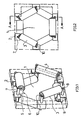
- a belt carrier having a central opening 1 for a tubular conveyor belt (not shown) has a rectangular frame 2, partially shown by dashed lines, of an angle profile. Connected to the frame 2 are a total of six support rollers 3, which are arranged alternately in the circumferential direction on the front and rear side of the frame 2 in the conveying direction.
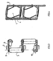
- the support rollers 3 each have a pivot pin 4, which is bolted to its two end faces with a plate 5 of a connecting part 6.
- a sleeve 7 is formed by bending the plate edge.
- the axle bolts 4 of the six support rollers 3 are connected to each other by a bolt 8 which is passed through two sleeves 7 and provided in the frame 2 opening.
- the bolt 8 and a nut 9 the sleeves are screwed together, the frame 2 is clamped between the sleeves.
- the plates 5 of the connecting parts 6 have for screwing with the axle bolts 4 each have a slot in order to adjust the required position of the axle pin 4 accurately.
- FIG. 5 Reference is made where part of a belt carrier is shown with support rollers 3a, the role holder without additional frame exclusively from the support rollers 3a receiving axle 4a and the axle pin 4a connecting parts 11 consists.
- the connecting parts 11 extend in their longitudinal extent perpendicular to the axle bolts and are integrally formed from mutually twisted, elongated blocks 12 and 13. Each of the blocks 12 and 13 is bolted to a pivot pin 4a.
- Fig. 7 shows, in each of the blocks 12 and 13, a slot 14 and 15 is provided for the screw connection with the respective axle.
Landscapes
- Engineering & Computer Science (AREA)
- Mechanical Engineering (AREA)
- Structure Of Belt Conveyors (AREA)
- Belt Conveyors (AREA)
- Package Frames And Binding Bands (AREA)
Description
- Die Erfindung betrifft einen Gurtträger für Schlauchförderer (Pipe conveyor) gemäß dem Oberbegriff des Anspruchs u.a. mit Tragrollen, die über den Umfang des schlauchförmigen Fördergurts verteilt und auf Achsbolzen gelagert sind, und mit einem den Fördergurt umgebenden Rollenhalter.
- Zum Tragen und Führen des schlauchförmigen Fördergurts ist eine Reihenanordnung aus einer Vielzahl solcher Gurtträger erforderlich. Der Rollenhalter durch Benutzung bekannter Gurtträger weist eine Platte mit einer zentralen Öffnung als Durchgang für den Fördergurt auf. Um den Öffnungsrand verteilt sind an der Platte über U-förmige Halteelemente die Tragrollen angebracht, deren Achsbolzen mit den U-Schenkeln der Halteelemente verbunden ist.
- Aus
JP 57151509 A - Der Erfindung liegt die Aufgabe zugrunde, einen neuen Gurtträger für Schlauchförderer zu schaffen, der bei geringem Materialeinsatz für den Rollenhalter eine verbesserte Schlauchführung ermöglicht.
- Diese Aufgabe wird gelöst durch einen Gurtträger mit den eingangs erwähnten Merkmalen, bei dem die Achsbolzen unter Verstärkung eines den Rollenhalter bildenden Rahmens durch zu den Achsbolzen senkrechte Verbindungsbolzen miteinander und mit dem Rahmen verbunden sind oder die Achsbolzen zusammen mit die Enden der Achsbolzen verbindenden, sich in ihrer Länge senkrecht zu den Achsbolzen erstreckenden Verbindungsteilen allein den Rollenhalter bilden, wobei die Rollen abwechselnd in Förderrichtung des Fördergurts versetzt angeordnet sind.
- In dem Gurtträger nach der Erfindung übernehmen die Achsbolzen eine zusätzliche oder alleinige Tragfunktion. Bei geschlossenem Stützring für den Fördergurt kann am übrigen Rollenhalter Material eingespart werden.
- Vorzugsweise bilden die verbundenen Achsbolzen, in Förderrichtung gesehen, ein Vieleck, vorzugsweise Sechseck, wobei die Länge der Vieleckseiten im wesentlichen gleich der Länge der Achsbolzen ist.
- Zweckmäßig sind die miteinander verbundenen Achsbolzen abwechselnd auf der in Förderrichtung vorderen und hinteren Seite des Rahmens angeordnet. Vorteilhaft ergeben sich so zueinander in Förderrichtung versetzte Stützstellen am Fördergurt.
- Vorzugsweise sind die Verbindungsbolzen als Schraubenbolzen ausgebildet und durch mit den Achsbolzen verbundene Hülsen geführt sind. Durch die Schraubenbolzen kann zwischen jeweils zwei Hülsen eine Schraubverbindung hergestellt sein.
- In der bevorzugten Ausführungsform ist der Schraubenbolzen durch eine Öffnung in dem Rahmen hindurchgeführt und der Rahmen ist zwischen den beiden durch den Schraubenbolzen verschraubten Hülsen eingeklemmt. Somit ist eine kraftschlüssige Verbindung sowohl zwischen den Achsbolzen und dem Rahmen als auch zwischen den Achsbolzen untereinander hergestellt, so dass die Achsbolzen zusätzliche Tragfunktionen übernehmen. Entsprechend schwach kann der Rahmen ausgebildet sein.
- Zweckmäßig ist die Hülse an einer stirnseitig mit dem Achsbolzen verbundenen Platte gebildet, wobei die Hülse vorzugsweise in der Art eines Scharnierteils durch Abbiegung des Plattenrandes hergestellt ist. Die Platte bildet eine Seitenführung für die Rollen. Zur Befestigung der Platte am Achsbolzen kann ein Langloch vorgesehen sein, welches erforderliche Feinjustierungen der Lage des Achsbolzens ermöglicht.
- Die Erfindung wird nachfolgend anhand eines Ausführungsbeispiels und der beiliegenden, sich auf dieses Ausführungsbeispiel beziehenden Zeichnungen näher erläutert. Es zeigen:
- Fig. 1
- eine Teilansicht eines Gurtträgers für einen Fördergurt eines Schlauch- förderers in perspektivischer Darstellung,
- Fig. 2
- eine Vorderansicht des Trägers von
Fig. 1 , - Fig. 3
- eine Seitenansicht des Trägers von
Fig. 1 gemäß Schnittlinie A-A inFig. 2 , - Fig. 4
- eine die Anordnung der Achsbolzen der Tragrollen des Trägers von
Fig. 1 verdeutlichende Darstellung, - Fig. 5
- eine Teilansicht eines Gurtträgers gemäß einem weiteren Ausführungsbei- spiel für die vorliegende Erfindung, und
- Fig. 6 und 7
- für den Gurtträger von
Fig. 5 verwendete Verbindungsteile in ver- schiedenen Ansichten. - Ein Gurtträger mit einer zentralen Öffnung 1 für einen schlauchförmigen Fördergurt (nicht gezeigt) weist einen zum Teil durch Strichlinien dargestellten rechteckigen Rahmen 2 aus einem Winkelprofil auf. Verbunden mit dem Rahmen 2 sind insgesamt sechs Tragrollen 3, die in Umfangsrichtung abwechselnd auf der in Förderrichtung vorderen und hinteren Seite des Rahmens 2 angeordnet sind.
- Die Tragrollen 3 weisen jeweils einen Achsbolzen 4 auf, welcher an seinen beiden Stirnseiten mit einer Platte 5 eines Verbindungsteils 6 verschraubt ist.
- An jedem Verbindungsteil 6 ist durch Abbiegung des Plattenrandes eine Hülse 7 gebildet. Die Achsbolzen 4 der sechs Tragrollen 3 sind untereinander jeweils durch einen Schraubenbolzen 8 verbunden, der durch zwei Hülsen 7 und eine im Rahmen 2 vorgesehene Öffnung hindurchgeführt ist. Durch den Schraubenbolzen 8 und eine Mutter 9 sind die Hülsen miteinander verschraubt, wobei der Rahmen 2 zwischen den Hülsen eingeklemmt ist.
- Somit ist sowohl zwischen den beiden Hülsen als auch zwischen den Hülsen und dem Rahmen eine kraftschlüssige Verbindung hergestellt, so dass die auf die Rollen einwirkenden Lasten sowohl über den Rahmen 2 als auch über die Achsbolzen 4 abgetragen werden. Der Rahmen 2 kann daher unter Einsparung von Material verhältnismäßig schwach ausgebildet sein.
- Die Platten 5 der Verbindungsteile 6 weisen zur Verschraubung mit den Achsbolzen 4 jeweils ein Langloch auf, um die erforderliche Lage der Achsbolzen 4 genau einstellen zu können.
- Es wird nun auf
Fig. 5 Bezug genommen, wo ausschnittsweise ein Gurtträger mit Tragrollen 3a gezeigt ist, deren Rollenhalter ohne zusätzlichen Rahmen ausschließlich aus die Tragrollen 3a aufnehmenden Achsbolzen 4a und die Achsbolzen 4a verbindenden Teilen 11 besteht. - In dem betreffenden Ausführungsbeispiel erstrecken sich die Verbindungsteile 11 in ihrer Längsausdehnung senkrecht zu den Achsbolzen und sind einstückig aus gegeneinander verdrehten, länglichen Blöcken 12 und 13 gebildet. Jeder der Blöcke 12 und 13 ist mit einem Achsbolzen 4a verschraubt.
- Wie aus
Fig. 7 hervorgeht, ist in jedem der Blöcke 12 und 13 ein Langloch 14 bzw. 15 für die Verschraubung mit dem betreffenden Achsbolzen vorgesehen.
Claims (10)
- Gurtträger für Schlauchförderer mit Tragrollen (3), die über den Umfang des schlauchförmigen Fördergurts verteilt und auf Achsbolzen (4) gelagert sind, und mit einem den Fördergurt umgebenden Rollenhalter, dadurch gekennzeichnet, dass die Achsbolzen (4) unter Verstärkung eines den Rollenhalter bildenden Rahmens (2) durch zu den Achsbolzen (4) senkrechte Verbindungsbolzen (8) miteinander und mit dem Rahmen (2) verbunden sind oder dass die Achsbolzen (4a) zusammen mit die Enden der Achsbolzen (4a) verbindenden, sich in ihrer Länge senkrecht zu den Achsbolzen (4a) ersteckenden Verbindungsteilen (11) allein den Rollenhalter bilden, wobei die Tragrollen (3) abwechselnd in Förderrichtung des Fördergurts versetzt angeordnet sind.
- Gurtträger nach Anspruch 1,
dadurch gekennzeichnet,
dass die verbundenen Achsbolzen (4), in Förderrichtung gesehen, ein Vieleck bilden, wobei die Länge der Vieleckseiten im wesentlichen gleich der Länge der Achsbolzen (4) ist. - Gurtträger nach Anspruch 1 oder 2,
dadurch gekennzeichnet,
dass die miteinander verbundenen Achsbolzen (4) abwechselnd auf der in Förderrichtung vorderen und hinteren Seite des Rahmens (2) angeordnet sind. - Gurtträger nach einem der Ansprüche 1 bis 3,
dadurch gekennzeichnet,
dass der Verbindungsbolzen (8) durch mit den Achsbolzen (4) verbundene Hülsen (7) hindurchgeführt ist. - Gurtträger nach Anspruch 4,
dadurch gekennzeichnet,
dass der Verbindungsbolzen ein Schraubenbolzen (8) zur Herstellung einer Schraubverbindung (8,9) zwischen den Hülsen (7) ist. - Gurtträger nach Anspruch 5,
dadurch gekennzeichnet,
dass der Schraubenbolzen (8) durch eine Öffnung in dem Rahmen (2) hindurchgeführt und der Rahmen (2) durch die Schraubverbindung (8,9) zwischen den Hülsen (7) eingeklemmt ist. - Gurtträger nach einem der Ansprüche 4 bis 6,
dadurch gekennzeichnet,
dass die Hülse (7) an einer stirnseitig mit dem Achsbolzen (4) verbundenen Platte (5) gebildet ist. - Gurtträger nach Anspruch 7,
dadurch gekennzeichnet,
dass die Hülse (7) durch Abbiegen des Randes der Platte (5) gebildet ist. - Gurtträger nach Anspruch 1,
dadurch gekennzeichnet,
dass die Verbindungsteile (11), vorzugsweise einstückig, aus zueinander verdrehten Blöcken (12,13) hergestellt sind. - Gurtträger nach Anspruch 9,
dadurch gekennzeichnet,
dass die Verbindungsteile (11), vorzugsweise über Langlöcher (14,15), mit den Achsbolzen (40) verschraubt sind.
Applications Claiming Priority (2)
| Application Number | Priority Date | Filing Date | Title |
|---|---|---|---|
| DE102004051533A DE102004051533A1 (de) | 2004-08-07 | 2004-10-22 | Gurtträger für Schlauchförderer |
| PCT/EP2005/011116 WO2006045463A2 (de) | 2004-10-22 | 2005-10-15 | Gurtträger für schlauchförderer |
Publications (2)
| Publication Number | Publication Date |
|---|---|
| EP1802541A2 EP1802541A2 (de) | 2007-07-04 |
| EP1802541B1 true EP1802541B1 (de) | 2010-06-30 |
Family
ID=35592574
Family Applications (1)
| Application Number | Title | Priority Date | Filing Date |
|---|---|---|---|
| EP05794803A Expired - Lifetime EP1802541B1 (de) | 2004-10-22 | 2005-10-15 | Gurtträger für schlauchförderer |
Country Status (4)
| Country | Link |
|---|---|
| EP (1) | EP1802541B1 (de) |
| AT (1) | ATE472497T1 (de) |
| DE (1) | DE502005009837D1 (de) |
| WO (1) | WO2006045463A2 (de) |
Family Cites Families (6)
| Publication number | Priority date | Publication date | Assignee | Title |
|---|---|---|---|---|
| JPS57151509A (en) * | 1981-03-11 | 1982-09-18 | Daiki Kogyo Kk | Vertical belt conveyer |
| JPS6124493Y2 (de) | 1981-03-12 | 1986-07-23 | ||
| DE8903429U1 (de) * | 1989-03-18 | 1990-07-26 | Lisega GmbH, 2730 Zeven | Rollenlager zur Abstützung von Rohren einer Rohrleitung u. dgl. |
| JP3477580B2 (ja) | 1993-06-18 | 2003-12-10 | 株式会社ブリヂストン | ベルトコンベヤ |
| DE19925514A1 (de) | 1999-06-02 | 2000-12-07 | Koch Transp Technik Gmbh | Schlauchbandförderer |
| US6390287B2 (en) * | 1999-06-10 | 2002-05-21 | The Robbins Company | Self-adjusting carrying idler assembly |
-
2005
- 2005-10-15 EP EP05794803A patent/EP1802541B1/de not_active Expired - Lifetime
- 2005-10-15 AT AT05794803T patent/ATE472497T1/de active
- 2005-10-15 WO PCT/EP2005/011116 patent/WO2006045463A2/de not_active Ceased
- 2005-10-15 DE DE502005009837T patent/DE502005009837D1/de not_active Expired - Lifetime
Also Published As
| Publication number | Publication date |
|---|---|
| ATE472497T1 (de) | 2010-07-15 |
| WO2006045463A3 (de) | 2006-06-01 |
| DE502005009837D1 (de) | 2010-08-12 |
| EP1802541A2 (de) | 2007-07-04 |
| WO2006045463A2 (de) | 2006-05-04 |
Similar Documents
| Publication | Publication Date | Title |
|---|---|---|
| DE602005002354T2 (de) | In den enden eines förderbands eingebaute verbindungselemente | |
| EP2848558B1 (de) | Justiersystem | |
| DE3506947A1 (de) | Schlauch-bandfoerderer | |
| DE2145812A1 (de) | Trag- und Fahrkette für Rollenförderer | |
| DE60105103T2 (de) | Förderrollen mit auswechselbarem Zugelemente | |
| DE4025706C2 (de) | Plattenförderband | |
| EP2301680A1 (de) | Spaltsieb und Haltelehre für dessen Herstellung | |
| DE3705914A1 (de) | Befestigungsvorrichtung fuer den mitnehmer von kettenfoerderern | |
| EP3771847A1 (de) | Riemenschloss und riemen | |
| EP0561198B1 (de) | Gurtförderer | |
| DE3130953C3 (de) | Zweiteiliges Kratzeisen für Mittelkettenförderer | |
| AT393110B (de) | Mitnehmeranordnung | |
| DE60127488T2 (de) | Flexibeler Kettenförderer | |
| EP0450133B2 (de) | Förderbandabstreifer mit segmentiertem Schaber | |
| EP3508443B1 (de) | Förderbrücke und förderanordnung mit streckenförderer und förderbrücke | |
| DE3313196C1 (de) | Vorrichtung zum Spannen eines bandförmigen Förderorganes | |
| DE102004051533A1 (de) | Gurtträger für Schlauchförderer | |
| EP1574356B1 (de) | Förderstrecke für Buchblocks in einer Einrichtung zur Herstellung gebundener Druckerzeugnisse | |
| DE3313108C2 (de) | ||
| EP1802541A2 (de) | Gurtträger für schlauchförderer | |
| EP1849723B1 (de) | Förderkette | |
| DE3913576C2 (de) | ||
| DE69709711T2 (de) | Schneckenförderer | |
| DE102008008807B3 (de) | Förderkette | |
| EP1624983B1 (de) | Vorrichtung zum entfernen von beulen |
Legal Events
| Date | Code | Title | Description |
|---|---|---|---|
| PUAI | Public reference made under article 153(3) epc to a published international application that has entered the european phase |
Free format text: ORIGINAL CODE: 0009012 |
|
| AK | Designated contracting states |
Kind code of ref document: A2 Designated state(s): AT BE BG CH CY CZ DE DK EE ES FI FR GB GR HU IE IS IT LI LT LU LV MC NL PL PT RO SE SI SK TR |
|
| 17P | Request for examination filed |
Effective date: 20070504 |
|
| DAX | Request for extension of the european patent (deleted) | ||
| RAP1 | Party data changed (applicant data changed or rights of an application transferred) |
Owner name: FLSMIDTH KOCH GMBH |
|
| 17Q | First examination report despatched |
Effective date: 20080909 |
|
| TPAC | Observations filed by third parties |
Free format text: ORIGINAL CODE: EPIDOSNTIPA |
|
| GRAP | Despatch of communication of intention to grant a patent |
Free format text: ORIGINAL CODE: EPIDOSNIGR1 |
|
| GRAS | Grant fee paid |
Free format text: ORIGINAL CODE: EPIDOSNIGR3 |
|
| GRAA | (expected) grant |
Free format text: ORIGINAL CODE: 0009210 |
|
| AK | Designated contracting states |
Kind code of ref document: B1 Designated state(s): AT BE BG CH CY CZ DE DK EE ES FI FR GB GR HU IE IS IT LI LT LU LV MC NL PL PT RO SE SI SK TR |
|
| REG | Reference to a national code |
Ref country code: GB Ref legal event code: FG4D Free format text: NOT ENGLISH Ref country code: CH Ref legal event code: EP |
|
| REG | Reference to a national code |
Ref country code: CH Ref legal event code: NV Representative=s name: ALDO ROEMPLER PATENTANWALT |
|
| REG | Reference to a national code |
Ref country code: IE Ref legal event code: FG4D Free format text: LANGUAGE OF EP DOCUMENT: GERMAN |
|
| REF | Corresponds to: |
Ref document number: 502005009837 Country of ref document: DE Date of ref document: 20100812 Kind code of ref document: P |
|
| REG | Reference to a national code |
Ref country code: GR Ref legal event code: EP Ref document number: 20100402099 Country of ref document: GR |
|
| REG | Reference to a national code |
Ref country code: NL Ref legal event code: VDEP Effective date: 20100630 |
|
| PG25 | Lapsed in a contracting state [announced via postgrant information from national office to epo] |
Ref country code: LT Free format text: LAPSE BECAUSE OF FAILURE TO SUBMIT A TRANSLATION OF THE DESCRIPTION OR TO PAY THE FEE WITHIN THE PRESCRIBED TIME-LIMIT Effective date: 20100630 Ref country code: SE Free format text: LAPSE BECAUSE OF FAILURE TO SUBMIT A TRANSLATION OF THE DESCRIPTION OR TO PAY THE FEE WITHIN THE PRESCRIBED TIME-LIMIT Effective date: 20100630 |
|
| LTIE | Lt: invalidation of european patent or patent extension |
Effective date: 20100630 |
|
| PG25 | Lapsed in a contracting state [announced via postgrant information from national office to epo] |
Ref country code: LV Free format text: LAPSE BECAUSE OF FAILURE TO SUBMIT A TRANSLATION OF THE DESCRIPTION OR TO PAY THE FEE WITHIN THE PRESCRIBED TIME-LIMIT Effective date: 20100630 Ref country code: FI Free format text: LAPSE BECAUSE OF FAILURE TO SUBMIT A TRANSLATION OF THE DESCRIPTION OR TO PAY THE FEE WITHIN THE PRESCRIBED TIME-LIMIT Effective date: 20100630 Ref country code: SI Free format text: LAPSE BECAUSE OF FAILURE TO SUBMIT A TRANSLATION OF THE DESCRIPTION OR TO PAY THE FEE WITHIN THE PRESCRIBED TIME-LIMIT Effective date: 20100630 |
|
| PG25 | Lapsed in a contracting state [announced via postgrant information from national office to epo] |
Ref country code: PL Free format text: LAPSE BECAUSE OF FAILURE TO SUBMIT A TRANSLATION OF THE DESCRIPTION OR TO PAY THE FEE WITHIN THE PRESCRIBED TIME-LIMIT Effective date: 20100630 |
|
| REG | Reference to a national code |
Ref country code: HU Ref legal event code: AG4A Ref document number: E008862 Country of ref document: HU |
|
| PG25 | Lapsed in a contracting state [announced via postgrant information from national office to epo] |
Ref country code: NL Free format text: LAPSE BECAUSE OF FAILURE TO SUBMIT A TRANSLATION OF THE DESCRIPTION OR TO PAY THE FEE WITHIN THE PRESCRIBED TIME-LIMIT Effective date: 20100630 Ref country code: EE Free format text: LAPSE BECAUSE OF FAILURE TO SUBMIT A TRANSLATION OF THE DESCRIPTION OR TO PAY THE FEE WITHIN THE PRESCRIBED TIME-LIMIT Effective date: 20100630 |
|
| REG | Reference to a national code |
Ref country code: IE Ref legal event code: FD4D |
|
| PG25 | Lapsed in a contracting state [announced via postgrant information from national office to epo] |
Ref country code: SK Free format text: LAPSE BECAUSE OF FAILURE TO SUBMIT A TRANSLATION OF THE DESCRIPTION OR TO PAY THE FEE WITHIN THE PRESCRIBED TIME-LIMIT Effective date: 20100630 Ref country code: RO Free format text: LAPSE BECAUSE OF FAILURE TO SUBMIT A TRANSLATION OF THE DESCRIPTION OR TO PAY THE FEE WITHIN THE PRESCRIBED TIME-LIMIT Effective date: 20100630 Ref country code: CZ Free format text: LAPSE BECAUSE OF FAILURE TO SUBMIT A TRANSLATION OF THE DESCRIPTION OR TO PAY THE FEE WITHIN THE PRESCRIBED TIME-LIMIT Effective date: 20100630 Ref country code: CY Free format text: LAPSE BECAUSE OF FAILURE TO SUBMIT A TRANSLATION OF THE DESCRIPTION OR TO PAY THE FEE WITHIN THE PRESCRIBED TIME-LIMIT Effective date: 20100630 Ref country code: PT Free format text: LAPSE BECAUSE OF FAILURE TO SUBMIT A TRANSLATION OF THE DESCRIPTION OR TO PAY THE FEE WITHIN THE PRESCRIBED TIME-LIMIT Effective date: 20101102 Ref country code: IS Free format text: LAPSE BECAUSE OF FAILURE TO SUBMIT A TRANSLATION OF THE DESCRIPTION OR TO PAY THE FEE WITHIN THE PRESCRIBED TIME-LIMIT Effective date: 20101030 |
|
| PG25 | Lapsed in a contracting state [announced via postgrant information from national office to epo] |
Ref country code: IT Free format text: LAPSE BECAUSE OF FAILURE TO SUBMIT A TRANSLATION OF THE DESCRIPTION OR TO PAY THE FEE WITHIN THE PRESCRIBED TIME-LIMIT Effective date: 20100630 |
|
| PG25 | Lapsed in a contracting state [announced via postgrant information from national office to epo] |
Ref country code: IE Free format text: LAPSE BECAUSE OF FAILURE TO SUBMIT A TRANSLATION OF THE DESCRIPTION OR TO PAY THE FEE WITHIN THE PRESCRIBED TIME-LIMIT Effective date: 20100630 Ref country code: DK Free format text: LAPSE BECAUSE OF FAILURE TO SUBMIT A TRANSLATION OF THE DESCRIPTION OR TO PAY THE FEE WITHIN THE PRESCRIBED TIME-LIMIT Effective date: 20100630 |
|
| BERE | Be: lapsed |
Owner name: FLSMIDTH KOCH G.M.B.H. Effective date: 20101031 |
|
| PLBE | No opposition filed within time limit |
Free format text: ORIGINAL CODE: 0009261 |
|
| STAA | Information on the status of an ep patent application or granted ep patent |
Free format text: STATUS: NO OPPOSITION FILED WITHIN TIME LIMIT |
|
| PG25 | Lapsed in a contracting state [announced via postgrant information from national office to epo] |
Ref country code: MC Free format text: LAPSE BECAUSE OF NON-PAYMENT OF DUE FEES Effective date: 20101031 |
|
| 26N | No opposition filed |
Effective date: 20110331 |
|
| GBPC | Gb: european patent ceased through non-payment of renewal fee |
Effective date: 20101015 |
|
| PG25 | Lapsed in a contracting state [announced via postgrant information from national office to epo] |
Ref country code: ES Free format text: LAPSE BECAUSE OF FAILURE TO SUBMIT A TRANSLATION OF THE DESCRIPTION OR TO PAY THE FEE WITHIN THE PRESCRIBED TIME-LIMIT Effective date: 20101011 |
|
| REG | Reference to a national code |
Ref country code: DE Ref legal event code: R097 Ref document number: 502005009837 Country of ref document: DE Effective date: 20110330 |
|
| PG25 | Lapsed in a contracting state [announced via postgrant information from national office to epo] |
Ref country code: BE Free format text: LAPSE BECAUSE OF NON-PAYMENT OF DUE FEES Effective date: 20101031 Ref country code: GB Free format text: LAPSE BECAUSE OF NON-PAYMENT OF DUE FEES Effective date: 20101015 |
|
| PG25 | Lapsed in a contracting state [announced via postgrant information from national office to epo] |
Ref country code: BG Free format text: LAPSE BECAUSE OF FAILURE TO SUBMIT A TRANSLATION OF THE DESCRIPTION OR TO PAY THE FEE WITHIN THE PRESCRIBED TIME-LIMIT Effective date: 20100630 Ref country code: LU Free format text: LAPSE BECAUSE OF NON-PAYMENT OF DUE FEES Effective date: 20101015 |
|
| PG25 | Lapsed in a contracting state [announced via postgrant information from national office to epo] |
Ref country code: TR Free format text: LAPSE BECAUSE OF FAILURE TO SUBMIT A TRANSLATION OF THE DESCRIPTION OR TO PAY THE FEE WITHIN THE PRESCRIBED TIME-LIMIT Effective date: 20100630 |
|
| PG25 | Lapsed in a contracting state [announced via postgrant information from national office to epo] |
Ref country code: BG Free format text: LAPSE BECAUSE OF FAILURE TO SUBMIT A TRANSLATION OF THE DESCRIPTION OR TO PAY THE FEE WITHIN THE PRESCRIBED TIME-LIMIT Effective date: 20100930 |
|
| REG | Reference to a national code |
Ref country code: DE Ref legal event code: R082 Ref document number: 502005009837 Country of ref document: DE Representative=s name: PATENTANWAELTE BERNHARDT/WOLFF PARTNERSCHAFT, DE Ref country code: DE Ref legal event code: R082 Ref document number: 502005009837 Country of ref document: DE Representative=s name: PATENTANWAELTE BERNHARDT/WOLFF PARTNERSCHAFT M, DE |
|
| REG | Reference to a national code |
Ref country code: FR Ref legal event code: PLFP Year of fee payment: 12 |
|
| REG | Reference to a national code |
Ref country code: FR Ref legal event code: PLFP Year of fee payment: 13 |
|
| REG | Reference to a national code |
Ref country code: FR Ref legal event code: PLFP Year of fee payment: 14 |
|
| PGFP | Annual fee paid to national office [announced via postgrant information from national office to epo] |
Ref country code: FR Payment date: 20220921 Year of fee payment: 18 |
|
| PGFP | Annual fee paid to national office [announced via postgrant information from national office to epo] |
Ref country code: AT Payment date: 20220926 Year of fee payment: 18 |
|
| P01 | Opt-out of the competence of the unified patent court (upc) registered |
Effective date: 20230507 |
|
| PGFP | Annual fee paid to national office [announced via postgrant information from national office to epo] |
Ref country code: GR Payment date: 20230913 Year of fee payment: 19 |
|
| PGFP | Annual fee paid to national office [announced via postgrant information from national office to epo] |
Ref country code: HU Payment date: 20230926 Year of fee payment: 19 Ref country code: DE Payment date: 20230906 Year of fee payment: 19 Ref country code: CH Payment date: 20231102 Year of fee payment: 19 |
|
| REG | Reference to a national code |
Ref country code: AT Ref legal event code: MM01 Ref document number: 472497 Country of ref document: AT Kind code of ref document: T Effective date: 20231015 |
|
| PG25 | Lapsed in a contracting state [announced via postgrant information from national office to epo] |
Ref country code: AT Free format text: LAPSE BECAUSE OF NON-PAYMENT OF DUE FEES Effective date: 20231015 |
|
| PG25 | Lapsed in a contracting state [announced via postgrant information from national office to epo] |
Ref country code: FR Free format text: LAPSE BECAUSE OF NON-PAYMENT OF DUE FEES Effective date: 20231031 Ref country code: AT Free format text: LAPSE BECAUSE OF NON-PAYMENT OF DUE FEES Effective date: 20231015 |
|
| REG | Reference to a national code |
Ref country code: DE Ref legal event code: R119 Ref document number: 502005009837 Country of ref document: DE |
|
| REG | Reference to a national code |
Ref country code: CH Ref legal event code: PL |
|
| PG25 | Lapsed in a contracting state [announced via postgrant information from national office to epo] |
Ref country code: DE Free format text: LAPSE BECAUSE OF NON-PAYMENT OF DUE FEES Effective date: 20250501 |
|
| PG25 | Lapsed in a contracting state [announced via postgrant information from national office to epo] |
Ref country code: HU Free format text: LAPSE BECAUSE OF NON-PAYMENT OF DUE FEES Effective date: 20241016 |
|
| PG25 | Lapsed in a contracting state [announced via postgrant information from national office to epo] |
Ref country code: GR Free format text: LAPSE BECAUSE OF NON-PAYMENT OF DUE FEES Effective date: 20250512 |
|
| PG25 | Lapsed in a contracting state [announced via postgrant information from national office to epo] |
Ref country code: CH Free format text: LAPSE BECAUSE OF NON-PAYMENT OF DUE FEES Effective date: 20241031 |