EP1801666A2 - Diffuses Reflexionshologramm, Hologramm für Reflexionshologrammfarbfilter etc. und solche Hologramme verwendende reflektive Anzeigevorrichtung - Google Patents
Diffuses Reflexionshologramm, Hologramm für Reflexionshologrammfarbfilter etc. und solche Hologramme verwendende reflektive Anzeigevorrichtung Download PDFInfo
- Publication number
- EP1801666A2 EP1801666A2 EP07102044A EP07102044A EP1801666A2 EP 1801666 A2 EP1801666 A2 EP 1801666A2 EP 07102044 A EP07102044 A EP 07102044A EP 07102044 A EP07102044 A EP 07102044A EP 1801666 A2 EP1801666 A2 EP 1801666A2
- Authority
- EP
- European Patent Office
- Prior art keywords
- hologram
- light
- volume
- reflection type
- photosensitive material
- Prior art date
- Legal status (The legal status is an assumption and is not a legal conclusion. Google has not performed a legal analysis and makes no representation as to the accuracy of the status listed.)
- Granted
Links
- 239000000463 material Substances 0.000 claims abstract description 136
- 239000004973 liquid crystal related substance Substances 0.000 claims abstract description 57
- 238000005286 illumination Methods 0.000 claims abstract description 34
- 230000005540 biological transmission Effects 0.000 claims description 55
- 238000004519 manufacturing process Methods 0.000 claims description 27
- 238000010521 absorption reaction Methods 0.000 claims description 23
- 239000002131 composite material Substances 0.000 claims description 11
- 230000003595 spectral effect Effects 0.000 claims description 10
- 230000001427 coherent effect Effects 0.000 claims description 7
- 239000006185 dispersion Substances 0.000 claims description 6
- 238000002834 transmittance Methods 0.000 claims description 6
- 238000009792 diffusion process Methods 0.000 abstract description 25
- 206010042674 Swelling Diseases 0.000 description 128
- 230000008961 swelling Effects 0.000 description 128
- 239000010408 film Substances 0.000 description 100
- 239000000178 monomer Substances 0.000 description 44
- 238000000034 method Methods 0.000 description 39
- 230000000149 penetrating effect Effects 0.000 description 26
- 230000009849 deactivation Effects 0.000 description 18
- 239000003086 colorant Substances 0.000 description 15
- 239000003795 chemical substances by application Substances 0.000 description 14
- 210000002858 crystal cell Anatomy 0.000 description 12
- 230000001276 controlling effect Effects 0.000 description 9
- 239000000654 additive Substances 0.000 description 7
- 230000000996 additive effect Effects 0.000 description 7
- 239000011230 binding agent Substances 0.000 description 7
- 239000003999 initiator Substances 0.000 description 7
- 239000011159 matrix material Substances 0.000 description 7
- 229920000642 polymer Polymers 0.000 description 7
- 230000004048 modification Effects 0.000 description 6
- 238000012986 modification Methods 0.000 description 6
- 238000011282 treatment Methods 0.000 description 6
- 238000010438 heat treatment Methods 0.000 description 5
- 230000001678 irradiating effect Effects 0.000 description 5
- 230000008859 change Effects 0.000 description 4
- 238000010276 construction Methods 0.000 description 4
- 230000010076 replication Effects 0.000 description 4
- 230000009471 action Effects 0.000 description 3
- 238000013459 approach Methods 0.000 description 3
- 239000011521 glass Substances 0.000 description 3
- 230000003287 optical effect Effects 0.000 description 3
- 230000001105 regulatory effect Effects 0.000 description 3
- 239000000758 substrate Substances 0.000 description 3
- 229920002799 BoPET Polymers 0.000 description 2
- 238000005520 cutting process Methods 0.000 description 2
- 230000000694 effects Effects 0.000 description 2
- 238000010894 electron beam technology Methods 0.000 description 2
- 230000035945 sensitivity Effects 0.000 description 2
- 238000000926 separation method Methods 0.000 description 2
- CTQNGGLPUBDAKN-UHFFFAOYSA-N O-Xylene Chemical compound CC1=CC=CC=C1C CTQNGGLPUBDAKN-UHFFFAOYSA-N 0.000 description 1
- XAGFODPZIPBFFR-UHFFFAOYSA-N aluminium Chemical compound [Al] XAGFODPZIPBFFR-UHFFFAOYSA-N 0.000 description 1
- 229910052782 aluminium Inorganic materials 0.000 description 1
- 239000011324 bead Substances 0.000 description 1
- 230000000295 complement effect Effects 0.000 description 1
- 239000013039 cover film Substances 0.000 description 1
- 230000003111 delayed effect Effects 0.000 description 1
- 230000001419 dependent effect Effects 0.000 description 1
- 238000009826 distribution Methods 0.000 description 1
- 230000002349 favourable effect Effects 0.000 description 1
- 230000004313 glare Effects 0.000 description 1
- 239000007788 liquid Substances 0.000 description 1
- 230000008569 process Effects 0.000 description 1
- 230000001902 propagating effect Effects 0.000 description 1
- 238000009751 slip forming Methods 0.000 description 1
- 238000003860 storage Methods 0.000 description 1
- 239000008096 xylene Substances 0.000 description 1
Images


Classifications
-
- G—PHYSICS
- G03—PHOTOGRAPHY; CINEMATOGRAPHY; ANALOGOUS TECHNIQUES USING WAVES OTHER THAN OPTICAL WAVES; ELECTROGRAPHY; HOLOGRAPHY
- G03H—HOLOGRAPHIC PROCESSES OR APPARATUS
- G03H1/00—Holographic processes or apparatus using light, infrared or ultraviolet waves for obtaining holograms or for obtaining an image from them; Details peculiar thereto
- G03H1/26—Processes or apparatus specially adapted to produce multiple sub- holograms or to obtain images from them, e.g. multicolour technique
- G03H1/30—Processes or apparatus specially adapted to produce multiple sub- holograms or to obtain images from them, e.g. multicolour technique discrete holograms only
-
- G—PHYSICS
- G02—OPTICS
- G02B—OPTICAL ELEMENTS, SYSTEMS OR APPARATUS
- G02B5/00—Optical elements other than lenses
- G02B5/02—Diffusing elements; Afocal elements
- G02B5/0205—Diffusing elements; Afocal elements characterised by the diffusing properties
- G02B5/0252—Diffusing elements; Afocal elements characterised by the diffusing properties using holographic or diffractive means
-
- G—PHYSICS
- G02—OPTICS
- G02B—OPTICAL ELEMENTS, SYSTEMS OR APPARATUS
- G02B5/00—Optical elements other than lenses
- G02B5/20—Filters
- G02B5/203—Filters having holographic or diffractive elements
-
- G—PHYSICS
- G02—OPTICS
- G02B—OPTICAL ELEMENTS, SYSTEMS OR APPARATUS
- G02B5/00—Optical elements other than lenses
- G02B5/32—Holograms used as optical elements
-
- G—PHYSICS
- G02—OPTICS
- G02F—OPTICAL DEVICES OR ARRANGEMENTS FOR THE CONTROL OF LIGHT BY MODIFICATION OF THE OPTICAL PROPERTIES OF THE MEDIA OF THE ELEMENTS INVOLVED THEREIN; NON-LINEAR OPTICS; FREQUENCY-CHANGING OF LIGHT; OPTICAL LOGIC ELEMENTS; OPTICAL ANALOGUE/DIGITAL CONVERTERS
- G02F1/00—Devices or arrangements for the control of the intensity, colour, phase, polarisation or direction of light arriving from an independent light source, e.g. switching, gating or modulating; Non-linear optics
- G02F1/01—Devices or arrangements for the control of the intensity, colour, phase, polarisation or direction of light arriving from an independent light source, e.g. switching, gating or modulating; Non-linear optics for the control of the intensity, phase, polarisation or colour
- G02F1/13—Devices or arrangements for the control of the intensity, colour, phase, polarisation or direction of light arriving from an independent light source, e.g. switching, gating or modulating; Non-linear optics for the control of the intensity, phase, polarisation or colour based on liquid crystals, e.g. single liquid crystal display cells
- G02F1/133—Constructional arrangements; Operation of liquid crystal cells; Circuit arrangements
- G02F1/1333—Constructional arrangements; Manufacturing methods
- G02F1/1335—Structural association of cells with optical devices, e.g. polarisers or reflectors
- G02F1/133553—Reflecting elements
-
- G—PHYSICS
- G03—PHOTOGRAPHY; CINEMATOGRAPHY; ANALOGOUS TECHNIQUES USING WAVES OTHER THAN OPTICAL WAVES; ELECTROGRAPHY; HOLOGRAPHY
- G03H—HOLOGRAPHIC PROCESSES OR APPARATUS
- G03H1/00—Holographic processes or apparatus using light, infrared or ultraviolet waves for obtaining holograms or for obtaining an image from them; Details peculiar thereto
- G03H1/04—Processes or apparatus for producing holograms
- G03H1/18—Particular processing of hologram record carriers, e.g. for obtaining blazed holograms
-
- G—PHYSICS
- G02—OPTICS
- G02F—OPTICAL DEVICES OR ARRANGEMENTS FOR THE CONTROL OF LIGHT BY MODIFICATION OF THE OPTICAL PROPERTIES OF THE MEDIA OF THE ELEMENTS INVOLVED THEREIN; NON-LINEAR OPTICS; FREQUENCY-CHANGING OF LIGHT; OPTICAL LOGIC ELEMENTS; OPTICAL ANALOGUE/DIGITAL CONVERTERS
- G02F2203/00—Function characteristic
- G02F2203/03—Function characteristic scattering
-
- G—PHYSICS
- G03—PHOTOGRAPHY; CINEMATOGRAPHY; ANALOGOUS TECHNIQUES USING WAVES OTHER THAN OPTICAL WAVES; ELECTROGRAPHY; HOLOGRAPHY
- G03H—HOLOGRAPHIC PROCESSES OR APPARATUS
- G03H1/00—Holographic processes or apparatus using light, infrared or ultraviolet waves for obtaining holograms or for obtaining an image from them; Details peculiar thereto
- G03H1/04—Processes or apparatus for producing holograms
- G03H1/20—Copying holograms by holographic, i.e. optical means
- G03H1/202—Contact copy when the reconstruction beam for the master H1 also serves as reference beam for the copy H2
-
- G—PHYSICS
- G03—PHOTOGRAPHY; CINEMATOGRAPHY; ANALOGOUS TECHNIQUES USING WAVES OTHER THAN OPTICAL WAVES; ELECTROGRAPHY; HOLOGRAPHY
- G03H—HOLOGRAPHIC PROCESSES OR APPARATUS
- G03H1/00—Holographic processes or apparatus using light, infrared or ultraviolet waves for obtaining holograms or for obtaining an image from them; Details peculiar thereto
- G03H1/04—Processes or apparatus for producing holograms
- G03H1/0402—Recording geometries or arrangements
- G03H2001/0415—Recording geometries or arrangements for recording reflection holograms
- G03H2001/0417—Recording geometries or arrangements for recording reflection holograms for recording single beam Lippmann hologram wherein the object is illuminated by reference beam passing through the recording material
-
- G—PHYSICS
- G03—PHOTOGRAPHY; CINEMATOGRAPHY; ANALOGOUS TECHNIQUES USING WAVES OTHER THAN OPTICAL WAVES; ELECTROGRAPHY; HOLOGRAPHY
- G03H—HOLOGRAPHIC PROCESSES OR APPARATUS
- G03H1/00—Holographic processes or apparatus using light, infrared or ultraviolet waves for obtaining holograms or for obtaining an image from them; Details peculiar thereto
- G03H1/04—Processes or apparatus for producing holograms
- G03H1/18—Particular processing of hologram record carriers, e.g. for obtaining blazed holograms
- G03H2001/186—Swelling or shrinking the holographic record or compensation thereof, e.g. for controlling the reconstructed wavelength
-
- G—PHYSICS
- G03—PHOTOGRAPHY; CINEMATOGRAPHY; ANALOGOUS TECHNIQUES USING WAVES OTHER THAN OPTICAL WAVES; ELECTROGRAPHY; HOLOGRAPHY
- G03H—HOLOGRAPHIC PROCESSES OR APPARATUS
- G03H1/00—Holographic processes or apparatus using light, infrared or ultraviolet waves for obtaining holograms or for obtaining an image from them; Details peculiar thereto
- G03H1/22—Processes or apparatus for obtaining an optical image from holograms
- G03H1/2249—Holobject properties
- G03H2001/2263—Multicoloured holobject
- G03H2001/2271—RGB holobject
-
- G—PHYSICS
- G03—PHOTOGRAPHY; CINEMATOGRAPHY; ANALOGOUS TECHNIQUES USING WAVES OTHER THAN OPTICAL WAVES; ELECTROGRAPHY; HOLOGRAPHY
- G03H—HOLOGRAPHIC PROCESSES OR APPARATUS
- G03H1/00—Holographic processes or apparatus using light, infrared or ultraviolet waves for obtaining holograms or for obtaining an image from them; Details peculiar thereto
- G03H1/22—Processes or apparatus for obtaining an optical image from holograms
- G03H1/2286—Particular reconstruction light ; Beam properties
- G03H2001/2289—Particular reconstruction light ; Beam properties when reconstruction wavelength differs form recording wavelength
-
- G—PHYSICS
- G03—PHOTOGRAPHY; CINEMATOGRAPHY; ANALOGOUS TECHNIQUES USING WAVES OTHER THAN OPTICAL WAVES; ELECTROGRAPHY; HOLOGRAPHY
- G03H—HOLOGRAPHIC PROCESSES OR APPARATUS
- G03H2222/00—Light sources or light beam properties
- G03H2222/36—Scanning light beam
-
- G—PHYSICS
- G03—PHOTOGRAPHY; CINEMATOGRAPHY; ANALOGOUS TECHNIQUES USING WAVES OTHER THAN OPTICAL WAVES; ELECTROGRAPHY; HOLOGRAPHY
- G03H—HOLOGRAPHIC PROCESSES OR APPARATUS
- G03H2223/00—Optical components
- G03H2223/24—Reflector; Mirror
-
- G—PHYSICS
- G03—PHOTOGRAPHY; CINEMATOGRAPHY; ANALOGOUS TECHNIQUES USING WAVES OTHER THAN OPTICAL WAVES; ELECTROGRAPHY; HOLOGRAPHY
- G03H—HOLOGRAPHIC PROCESSES OR APPARATUS
- G03H2230/00—Form or shape of the hologram when not registered to the substrate
- G03H2230/10—Microhologram not registered to the substrate
-
- G—PHYSICS
- G03—PHOTOGRAPHY; CINEMATOGRAPHY; ANALOGOUS TECHNIQUES USING WAVES OTHER THAN OPTICAL WAVES; ELECTROGRAPHY; HOLOGRAPHY
- G03H—HOLOGRAPHIC PROCESSES OR APPARATUS
- G03H2250/00—Laminate comprising a hologram layer
- G03H2250/44—Colour tuning layer
Definitions
- the present invention relates to a reflection type diffuse hologram that can be used for display devices such as liquid crystal display devices, a hologram for reflection hologram color filters, etc., and a reflection type display device using such holograms.
- Backlight used with a liquid crystal display device should have some scattering characteristics, so that the display device can have a wide viewing angle. So far, scattering characteristics have been imparted to backlight by use of beads or the like, but a problem with this is that too large an angle of diffusion results in wasteful illumination light loss.
- the present applicant has filed Japanese Patent Application No. 12170/1993 to come up with a color filter in which a hologram is used to achieve a remarkable increase in the efficiency of backlight used for liquid crystal display purposes, etc., and a liquid crystal display device that makes use of such a color filter.
- a hologram array 55 forming the color filter is spaced away from the side of a liquid crystal display element 56 upon which backlight 53 is to strike, said element being regularly divided into liquid crystal cells 56' (pixels).
- black matrices 54 On the back side of the liquid crystal display element 56 and between the liquid crystal cells 56' there are located black matrices 54.
- polarizing plates are arranged on the incident side of the hologram array 55, and the exit side of the liquid crystal display element 56.
- an absorption type of color filters which transmit light rays of colors corresponding to pixels R, G, and B.
- the hologram array 55 comprises micro-holograms 55' which are arranged in an array form at the same pitch as that of R, G, and B spectral pixels, corresponding to the period of repetition of R, G, and B spectral pixels, i.e., sets of liquid crystal cells 56', each including three adjoining liquid crystal cells 56' of the liquid crystal display element 6 as viewed in a plane direction of the drawing sheet.
- One micro-hologram 55' is located in line with each set of three adjoining liquid crystal cells 56' of the liquid crystal display element 6 as viewed in the plane direction of the drawing sheet.
- micro-holograms 55' are then arranged in a Fresnel zone plate form such that a green component ray of the backlight 3 incident on the hologram array 55 at an angle ⁇ with respect to its normal line is collected at a middle liquid crystal cell G of the three R, G, and B spectral pixels corresponding to each micro-hologram 55'.
- Each or the micro-hologram 55' in this case is constructed from a relief, phase, amplitude or other transmission type of hologram which has little, if any, dependence of diffraction efficiency on wavelength.
- the wording "little, if any, dependence of diffraction efficiency on wavelength” used herein is understood to refer specifically to a hologram of the type which diffracts all wavelengths by one diffraction grating, much unlike a Lippmann type hologram which diffracts a particular wavelength alone but does not substantially permit other wavelengths to be transmitted therethrough.
- the diffraction grating having little dependence of diffraction efficiency on wavelength diffracts different wavelengths at different angles of diffraction.
- the hologram array 55 is constructed and arranged such that the red wavelength component is diffractively collected at a red-representing liquid crystal cell R; the green wavelength component at a green-representing liquid crystal cell G; and the blue wavelength component at a blue-representing liquid crystal cell B, the color components pass through the corresponding liquid crystal cells 56' with no or little attenuation through the black matrices 4, so that color displays can be presented depending on the state of the liquid crystal cells 56' at the corresponding positions.
- the angle of incidence q of backlight 53 on the hologram array 55 is determined by various conditions including hologram-recording conditions, the thickness of hologram array 55, and the distance between the hologram array 55 and the liquid crystal display element 6.
- the hologram array 55 as a color filter in this way, the wavelength components of backlight used with a conventional color filter are allowed to strike on the liquid crystal cells 56' without immense absorption, so that the efficiency of utilization thereof can be greatly improved.
- the aforesaid hologram color filter proposed by the present applicant is applicable to only a color liquid crystal display device making use of backlight.
- this hologram color filter cannot diffract, and collect its wavelength components into desired positions.
- this hologram color filter can never be applied to a direct-view type of liquid crystal display device or other like device in which surrounding ambient light is used as illumination light, or any particular backlight source is not required.
- a swelling film is prepared by mixing a monomer or oligomer, a photopolymerization initiator, etc. with a binder polymer.
- the swelling film is irradiated with a given quantity of light before or after its close contact with a photopolymer or other photosensitive material having interference fringes recorded therein, so that a given proportion of the monomer or oligomer contained in the swelling film, on the one hand, is polymerized for deactivation and the amount of the remaining active monomer or oligomer, on the other hand, is controlled.
- the thus controlled amount of the monomer or oligomer is diffused, and swollen into the photosensitive material with interference fringes recorded therein, whereby fringe spacings are precisely controlled to any desired quantity to control reconstruction wavelengths to given ones.
- the photosensitive material with the interference fringe recorded therein is irradiated with light or otherwise heated to fix the diffused monomer or oligomer in the interference fringes, so that there can be obtained a hologram excelling in the storage stability of reconstructed colors.
- a color pattern can be formed on the hologram by allowing the illumination light to have a spatial distribution.
- Figure 29 illustrates the principles applied when the swelling agent (monomer or oligomer) contained in the swelling film is deactivated by irradiation with light after the swelling film has been brought into close contact with the photosensitive material
- Figure 30 depicts the principles applied when the swelling agent contained in the swelling film is deactivated by irradiation with light before the swelling film is brought into close contact with the photosensitive material.
- a volume hologram 64 as depicted in Figure 29(b) is obtained by striking object light 62 and reference light 63 on both sides of a photopolymer or other photosensitive material 61 to record an interference fringe therein.
- a swelling film 65 prepared by mixing a monomer or oligomer, a photopolymerization initiator, etc. with a binder polymer is then brought into close contact with the photosensitive material. Subsequently, either the hologram 64 or the swelling film 65 is irradiated with light 66, as depicted in Figures 29(d1) to (d3), before or at the same time as heating is carried out to increase the degree of diffusion of the penetrating monomer or oligomer in the swelling film 65.
- This irradiation with light 66 causes a part or all of the penetrating active monomer or oligomer in the swelling film 65 to be polymerized, and so deactivated, at a proportion corresponding to the quantity of irradiating light 66, so that the ability of the monomer or oligomer to penetrate (diffuse) vanishes substantially.
- the quantity of irradiating light 66 is large ( Figure 29(d1)), therefore, nearly all of the penetrating active monomer or oligomer in the swelling film 65 is deactivated, so that the monomer or oligomer does not substantially penetrate into the hologram 64 even upon heated.
- the hologram 64 subject to the swelling step in Figure 29(d1) does not substantially swell, and diffracts and reconstructs blue light.
- the quantity of irradiating light 66 is moderate ( Figure 29(d2))
- Figure 29(d2) about a half of the penetrating active monomer or oligomer in the swelling film 65 is deactivated.
- Another half of the penetrating monomer or oligomer penetrates into the hologram 64 upon heated, which in turn swells moderately.
- the hologram 64 subject to the swelling step shown in Figure 29(d2) diffracts, and reconstructs green light that is longer in wavelength than blue light.
- a volume hologram 64 is obtained as depicted in Figures 29(a) and (b).
- a swelling film 65 is prepared by mixing a monomer or oligomer, a photopolymerization initiator, etc. with a binder polymer.
- a part or all of the penetrating active monomer or oligomer contained therein is deactivated at a proportion corresponding to the quantity of light 66, so that the ability of the monomer or oligomer to penetrate (diffuse) vanishes.
- the swelling film 65 is prepared by mixing a monomer or oligomer, a photopolymerization initiator, etc. with a binder polymer, and so is similar to a photopolymer used for recording holograms. Therefore, the hologram-recording photopolymer may be used as the swelling film 65; that is, it is unnecessary to prepare any special swelling film.
- the aforesaid color pattern-making method proposed by the present applicant is to control the quantity of light with which the swelling film is irradiated before or after it is brought into close contact with a photosensitive material having interference fringes already recorded therein, thereby controlling the amount of the active monomer or oligomer contained in the swelling film, so that the proportion of swelling of the interference fringes (or the fringe spacings) can be controlled to regulate the color to be reconstructed to a given one.
- the color to be reconstructed is controlled by the quantity of irradiating light.
- Another object of the present invention is to provide a reflection type of direct-view color display device such as a color liquid crystal display device, which makes use of a hologram color filter already proposed by the present applicant but makes no use of any backlight source.
- Yet another object of the present invention is to provide a reflection type color display device such as a color liquid crystal display device, which uses a hologram reflection layer as a color filter but makes no use of any backlight source.
- Still yet another object of the present invention is to provide a hologram recording medium, and a hologram color display medium, which can all be utilized as a color filter of a reflection type color display device, and a method of making them.
- the objects mentioned above can be achieved by the provision of a reflection type diffuse hologram characterized by reflecting, and diffracting light incident thereon at an angle with respect to a normal direction while it is diffused within a desired angle range.
- the angle of incident light with respect to the normal direction may include 0°, or the angle of incidence may be 0°.
- the angle of diffusion lie within a range of 10° to 35°.
- Another reflection type diffuse hologram of the present invention is characterized by having been formed by allowing scattered light that diffuses within a desired angle range, and parallel light to strike on both sides of a volume hologram-recording photosensitive material, and interfere therein.
- the reflection type diffuse hologram may be located on a backlight side of a liquid crystal display device for diffuse illumination purposes.
- the present invention provides a method for fabricating a reflection type diffuse hologram characterized in that a transmission type diffusing plate having a diffusion angle characteristic within a desired angle range is located in close contact with, or in proximity to, a volume hologram-recording photosensitive material, and two light beams are allowed to strike on front and back sides of the combined diffusing plate and photosensitive material for interference recording.
- the transmission type diffusing plate used may be a diffusing plate of a 20% to 60% haze, an array of microlenses, a lenticular screen or the like.
- a reflection type of direct-view color display device using a hologram color filter according to the present invention - which is provided to achieve the objects mentioned above - comprises a hologram color filter composed of an array of element light-collecting holograms, each of said element light-collecting holograms comprising a hologram color filter for subjecting white light incident at a given angle with respect to a normal line of a hologram-recorded surface to wavelength dispersion in a direction substantially along said hologram-recorded surface for spectral diffraction, a reflection type hologram located in the vicinity of a light-collection surface thereof, and a transmission type spatial light modulator located between said hologram color filter and said reflection type hologram.
- the reflection type hologram has interference fringes recorded in the vicinity of a position on which white light strikes while said white light is separated into each spectral component of each color, said interference fringes reflecting light of wavelength of each color in an identical direction.
- the reflection type hologram may be of diffusibility.
- a liquid crystal display element may be used.
- a reflection type color display device of the present invention - which is provided to achieve the aforesaid object - is characterized by comprising a transmission type spatial light modulator comprising a collection of pixels, and having a controllable transmittance per pixel, and a reflection type hologram color filter located on a back side of said modulator.
- the reflection type hologram color filter comprises periodically arranged volume hologram elements varying in reflection, and diffraction wavelength for each position of the pixels in the transmission type spatial light modulator.
- the reflection type hologram color filter may be of diffusibililty.
- the reflection type hologram color filter has an absorption layer located on a back side thereof.
- the reflection type hologram color filter may be provided on its back side with an absorption type color filter, which is provided on its back side with a backlight source, so that color information is interchangeable when said backlight source is turned on, said color information being displayed on each pixel in the transmission type spatial light modulator.
- the transmission type spatial light modulator for instance, a liquid crystal display element, a polymer-dispersed type liquid crystal display element or the like may be used.
- a hologram-recorded medium of the present invention - which is provided to achieve the aforesaid object - is an imagewise or other pattern-recorded medium comprising a collection of pixels, characterized in that any one of a plurality of volume type diffraction gratings comprising volume holograms and differing from each other is assigned to at least a part of said pixels.
- a plurality of volume type diffraction gratings comprising volume holograms and differing from each other include at least three volume type diffraction gratings which are identical in orientation of grating surface with each other but different in grating spacing from each other.
- At least two of a plurality of mutually different volume type diffraction gratings are multi-recorded in at least a part of the pixels.
- a volume type diffraction grating that expresses red, a volume type diffraction grating that expresses green, and a volume type diffraction grating that expresses blue are assigned to three dot areas into which at least a part of the pixels is divided, or to three adjoining pixels, so that color tone or gradation is controlled by varying a dot percent occupied by said volume type diffraction gratings, or a diffraction efficiency ratio between said volume type diffraction gratings.
- the hologram-recorded medium of the present invention may have a reflecting layer on its back side.
- Each of pixels in the hologram-recorded medium of the present invention may be of diffusibility.
- the hologram-recorded medium of the present invention as mentioned above may be used as a reflection type hologram color filter.
- Such a hologram-recorded medium of the present invention is fabricated as recited below.
- the hologram color display medium of the present invention - which is provided to achieve the aforesaid objection - is a hologram color display medium having interference fringes of light recorded in a thickness direction of a film, characterized by using two swelling films each containing a penetrating monomer or oligomer that is diffusible externally from a surface of said film, said penetrating monomer or oligomer being deactivated according to a given deactivation pattern, so that said hologram is swollen by said penetrating monomer or oligomer diffused from both surfaces of said hologram at different degrees of swelling depending on position.
- the aforesaid two swelling films are brought into close contact with both surfaces of the aforesaid hologram, so that a two-dimensional diffraction pattern of two or more colors is obtained by the combination of a deactivation pattern of one swelling film with that of another swelling film.
- a color image may be expressed by means of a collection of color display micro-units, each comprising a combination of two or more micro-pixels displaying two or more different colors, and the dot percent of dots in each color display micro-unit may be varied to express each color display micro-unit in any desired color by additive color mixing. If, in this case, the interference fringes recorded in the hologram is designed such that diffraction efficiency changes depending on the positions of the color display micro-units, or the hologram itself or its diffraction-side surface is designed such that absorptance changes depending on the positions of the color display micro-units, it is then possible to control the brightness or luminance of each color display micro-unit.
- the hologram is a volume phase type hologram, and it is then preferable that the hologram is a hologram recorded in a photopolymer.
- the hologram color display medium of the present invention may be of diffusibility.
- Such a hologram color display medium of the present invention as mentioned above may be used in the form of a reflection type hologram color filter.
- the present invention provides a first method of fabricating a hologram color display medium including a hologram having interference fringes of light recorded in a thickness direction of a film, wherein two swelling films each containing a penetrating monomer or oligomer that is diffusible externally from a surface of said film, said penetrating monomer or oligomer being deactivated according to a given deactivation pattern, are used so that said hologram is swollen by said penetrating monomer or oligomer diffused from both surfaces of said hologram at different degrees of swelling depending on position, characterized in that before or after the close contact of the two swelling films, in which the penetrating monomer or oligomer contained in that position is deactivated by irradiation of a given or more quantity of light, with both surfaces of said hologram, said two swelling films are irradiated according to said given deactivation pattern with a given or more quantity of light, and said hologram with the thus deactivated swelling films
- the present invention provides a second method of fabricating a hologram color display medium including a hologram having interference fringes of light recorded in a thickness direction of a film, wherein two swelling films each containing a penetrating monomer or oligomer that is diffusible externally from a surface of said film, said penetrating monomer or oligomer being deactivated according to a given deactivation pattern, are used so that said hologram is swollen by said penetrating monomer or oligomer diffused from both surfaces of said hologram at different degrees of swelling depending on position, characterized in that before or after the close contact of one swelling film, in which the penetrating monomer or oligomer contained in that position is deactivated by irradiation of a given or more quantity of light, with one surface of said hologram, said one swelling film is irradiated according to said given deactivation pattern with a given or more quantity of light; said hologram with the thus deactivated swelling film brought into
- the hologram is a volume phase type hologram, and it is then preferable that the hologram is a hologram recorded in a photopolymer.
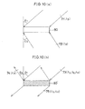
- FIG. 1 illustrates a typical arrangement of how to record a reflection type diffuse hologram according to the present invention.
- a diffusing plate 2 having a diffusion angle ⁇ (a maximum diffusion angle) is located into close contact with a hologram photosensitive material 1 such as a photopolymer which can record a volume hologram therein.
- Parallel light 3 is obliquely incident on the photosensitive material 1 at an angle of incidence ⁇ , while parallel light 4 is perpendicularly incident on the diffusing plate 2.
- the parallel light 4 passes through the diffusing plate 2 to become diffused light 5 having a diffusion angle ⁇ , which, in the photosensitive material 1, in turn interferes with the oblique parallel light 3 incident thereon from the opposite direction to produce interference fringes.
- a reflection (or Lippmann) type hologram is formed.
- parallel illumination light 11 is incident on a reflection type hologram 10 formed as depicted in Figure 1 at the same angle of incidence ⁇ at which the parallel light 3 has been incident obliquely on the material 1 to record the hologram 10, whereupon diffused light 12 whose diffusion angle ⁇ is the same as that of the diffused light 5 used to record the hologram 10 is reflected, and diffracted from the reflection type hologram 10.
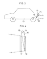
- a reflection type hologram 10 is mounted on a rear portion of a car 13 as sketched in Figure 3 as an example.
- Light from a light source 14 is converted through an optical system 15 (e.g., a paraboloidal mirror) into parallel light 16 to illuminate the reflection type hologram 10 obliquely from above.
- an optical system 15 e.g., a paraboloidal mirror
- the light 16 is reflected, and diffracted in the rearward direction of car 13 while the diffusion angle is limited to a desired angle of ⁇ , thereby showing that the preceding car is about to apply a brake or change direction.
- such a reflection type hologram 10 as mentioned above may be located on a backlight side of a liquid crystal display device 17 as depicted in Figure 4, for instance.
- Light from a light source 14 is converted through an optical system 15 (e.g., a paraboloidal mirror) into parallel light 16 to illuminate the reflection type hologram 10 obliquely from above.
- the light 16 is diffracted, and reflected onto the liquid crystal display device 17 while the diffusion angle is limited to the desired angle of ⁇ , so that the light 16 can arrive at the viewer through a transparent portion of the liquid crystal display device 17.
- the viewing angle of the liquid crystal display device spreads out to the angle ⁇ q, but the backlight is confined within the desired angle range, so that wasteful consumption of illumination light can be avoided.
- the reflection type diffuse hologram of the present invention is recorded using the diffusing plate 2 having a limited diffusion angle.
- an array of microlenses or a lenticular screen 22, as depicted in Figure 5 may be used as a diffuse optical element.
- the array of microlenses is an arrangement wherein axially symmetric microlenses are two-dimensionally located
- the lenticular screen is an arrangement wherein cylindrical microlenses are one-dimensionally located, each as shown in section in Figure 5.
- a reflection type diffuse hologram with a diffusion angle ⁇ corresponding to the collection or divergence angle of the microlenses or cylindrical microlenses forming the array or lenticular screen 22.
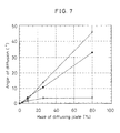
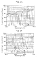
- the diffusing plate 2 was irradiated in the normal direction with object light 4 defined by a parallel beam of Kr laser light (of 647 nm wavelength) and, at the same time, the glass substrate 20 was irradiated at an angle of incidence of 60° with respect to the normal direction with reference light 3 defined by a parallel beam of the same Kr laser light.
- the ratio between the reference light and the object light was 1:1, and the combined exposure of the two light beams 3 and 4 was 200 mJ/cm 2 .
- the photosensitive material 1 Upon removed from the diffusing plate 2, the photosensitive material 1 was irradiated with 100 mJ/cm 2 of ultraviolet rays, and then heated at 120°C for 2 hours to obtain a reflection type diffuse hologram having a diffraction efficiency of 65% and a diffraction peak wavelength of 647 nm, and reflecting and diffracting parallel light at a diffusion angle of 12°, said parallel light incident at an angle of incidence of 60°.
- diffraction efficiency was determined by measuring transmittance with an automatic recording spectrophotometer (UV-3100PC made by Shimadzu Corporation), and subtracting that transmittance from 100%, and haze was expressed by a value found with NDH-1001DP made by Nippon Denshoku Co., Ltd.
- the reflection type diffuse hologram according to the present invention is a Lippmann type hologram. Therefore, it is also possible to achieve a reflection type hologram 10 capable of reconstructing not only diffused light 12 but also an image such as a 3M image by using the same reference light 3 as used to record scattered light 5 from the diffusing plate 2 or the microlens array or lenticular screen 22 and, before or after recording it, allowing object light to strike from behind the photosensitive material 1, said object light forming an image such a character or picture image in front of the photosensitive material 1 (on the side on which the reference light 3 is incident), thereby multi-recording them in the photosensitive material 1.
- reflection type diffuse hologram of the present invention and its fabrication method have been described with reference to its principles and some specific embodiments, it is understood that the present invention is not limited thereto, and so various modifications may be possible.
- the aforesaid reflection type diffuse hologram of the present invention is fabricated by the incidence of diffuse light diffusing within the desired angle range and parallel light on both sides of a volume hologram-recording photosensitive material wherein they interfere. It is thus possible to prevent light from a light source from diffusing at an angle larger than required, avoiding wasteful consumption of the light from the light source, and making bright displays and indications possible. Since the diffusing plate is a volume hologram, it is further possible to achieve easy fabrication of diffusing plates having given characteristics by replication.
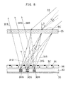
- FIG 8 is a sectional schematic of one embodiment of a reflection type of direct-view color display device constructed using a hologram color filter, for instance, one shown in Figure 28.
- a hologram color filter 55 is spaced away from a side of a transmission type spatial light modulator 36 on which ambient illumination light 33 is to strike, said modulator comprising a liquid crystal display element, a polymer-dispersed type liquid crystal (PDLC) display element, etc., which is regularly divided into pixels 36'.
- PDLC polymer-dispersed type liquid crystal
- a black matrix 54 is interposed between adjoining pixels 36' in the transmission type spatial light modulator 36. It is here noted that the distance between the hologram color filter 55 and the reflection type hologram 30 is selected such that it is substantially equal to the light-collecting (focal) distance of each micro-hologram 55'.
- the hologram color filter 55 comprises micro-holograms 55' which are arranged in an array form at the same pitch as that of R, G, and B spectral pixels, corresponding to the period of repetition of R, G, and B spectral pixels in the transmission type spatial light modulator 36, i.e., sets of three adjoining pixels 36' in the transmission type spatial light modulator 36, as viewed in a plane of the drawing sheet.
- One micro-hologram 55' is located in line with each set of three adjoining pixels 36' in the transmission type spatial light modulator 36, as viewed in the plane of the drawing sheet.
- micro-holograms 55' are then arranged in a Fresnel zone plate form such that a green component ray 31G of illumination light 33 incident on the hologram color filter 55 at an angle ⁇ with respect to its normal line is collected in the vicinity of a middle G pixel of the three R, G, and B pixels corresponding to each micro-hologram 55'.
- Each or the micro-hologram 55' in this case is constructed from a relief, phase, amplitude or other transmission type of hologram which has little, if any, dependence of diffraction efficient on wavelength.
- the wording "little, if any, dependence of diffraction efficiency on wavelength” used herein is understood to refer specifically to a hologram of the type which diffracts all wavelengths by one diffraction grating, much unlike a Lippmann type hologram which diffracts a particular wavelength alone but does not substantially permit other wavelengths to be transmitted therethrough.
- the diffraction grating having little dependence of diffraction efficiency on wavelength diffracts different wavelengths at different angles of diffraction.
- the ambient light 33 strikes at an angle of incidence ⁇ on the surface side of the hologram color filter 55.
- the light 33 is subject to wavelength dispersion by the hologram color filter 55, so that the light collection positions for wavelengths are dispersed in a direction parallel with the plane of the hologram color filter 55.
- the hologram color filter 55 is constructed and arranged such that red, green, and blue wavelength components 31R, 31G, and 31B are diffractively collected in the vicinity of the surface of the reflection type hologram 30 at positions of the pixels R, G, and B displaying red, green, and blue, respectively, the color components pass through the associated pixels 36' without undergoing substantial attenuation by the black matrices 54, and then arrive at the reflection type hologram 30 at the associated positions.
- the reflection type hologram 30 is a volume phase (Lippmann) type hologram, and interference fringes 30R, 30G, and 30B in the reflection type hologram 30 - which lie in the vicinity of positions where red, green, and blue diffracted components 31R, 31G, and 31B corresponding to the ambient light 33 having an angle of incidence ⁇ are collected - are formed to separately reflect light of red wavelength, light of green wavelength, and light of blue wavelength, respectively.
- volume phase (Lippmann) type hologram and interference fringes 30R, 30G, and 30B in the reflection type hologram 30 - which lie in the vicinity of positions where red, green, and blue diffracted components 31R, 31G, and 31B corresponding to the ambient light 33 having an angle of incidence ⁇ are collected - are formed to separately reflect light of red wavelength, light of green wavelength, and light of blue wavelength, respectively.
- the interference fringes 30R, 30G, and 30B are inclined such that the aforesaid red, green and blue diffracted components 31R, 31G, and 31B are converted by diffraction and reflection into reflected light 32R, 32G, and 32B, respectively, which in turn propagate in a substantially identical direction.
- the interference fringes 30R, 30G, and 30B in the reflection type hologram, too are continuously formed and distributed at positions corresponding to the pixels R, G, and B.
- the red wavelength component 31R strikes on the red-displaying pixel R where it is subject to intensity modulation depending on the state of that pixel, and then passes therethrough.
- This transmitted component is reflected by the interference fringe 30R in the reflection type hologram 30 into reflected light 32R in a certain direction, which in turn passes back through the pixel R from its rear side, and then strikes on, and passes through, the hologram color filter 55 without being now hardly diffracted, finally striking on the eye of the viewer positioned in that direction.
- the green, and blue wavelength components 31G, and 31B subject to spectral diffraction by the hologram color filter 55 strike on the green, and blue-displaying pixels G, and B where they are subject to intensity modulation depending on the states of those pixels, and then pass therethrough.
- the transmitted components are reflected by the interference fringes 30G, and 30B into reflected light 32G, and 32B in a certain direction, which in turn pass back through the pixels G, and B from their rear sides, and then strike on, and pass, through the hologram color filter 55 without being now hardly diffracted, finally striking on the eye of viewer positioned in that direction. It is thus possible to display color images by the combination of modulated states of the pixels R, G, and B.
- the direction of incidence and wavelength of the latter part do not comply with the diffraction conditions for the interference fringes 30R, 30G, and 30G, it passes through the reflection type hologram 30 to the light-absorbing layer 35 where it is absorbed; that is, it cannot be reflected onto the viewer.
- the hologram color filter 55 and reflection type hologram 30 in combination with the transmission type spatial light modulator 36 comprising a collection of pixels, for instance, a liquid crystal display device, it is thus possible to achieve a reflection type of direct-view color display device such as a color liquid crystal display device, which can use ambient light to present bright displays without using any backlight source.
- the hologram color filter of the present invention can be used with a reflection type hologram and in combination with a transmission type spatial light modulator comprising a collection of pixels such as a liquid crystal display device, thereby achieving a reflection type of direct-view color display device such as a color liquid crystal display device, which can use ambient light to present bright displays without using any backlight source.
- FIG 10 is a perspective view for illustrating how to record a volume type reflection hologram, and the action thereof.
- coherent parallel object light 71, and reference light 72, each of wavelength ⁇ B strike at angles of incidence of ⁇ 1 , and ⁇ 2 on both sides of a photopolymer or other hologram photosensitive material 80 that is thick with respect to the spatial frequency.
- the index B represents the wavelength of a blue zone, and that indices G, and R will hereinafter stand for the wavelengths of green, and red zones).
- the volume type reflection hologram is excellent in the ability to select wavelength, and angle, and so can control the half bandwidth of a diffraction wavelength region, the range of diffraction direction, etc. to some extent by selection of photosensitive material thickness, recording conditions, post-treatment conditions, etc.
- a composite reflection hologram 81 fabricated by periodically arranging sets of three micro-holograms with diffraction wavelengths lying in the blue, green, and red regions in an array form.
- illumination light or ambient light 82 is reflected, and diffracted by the composite reflection hologram 81 upon striking thereon from a given direction, and the thus reflected, and diffracted light 83 propagates in a given direction.
- a blue-reflecting and -diffracting hologram element 81B in the composite reflection hologram 81 diffracts only wavelength ⁇ B lying in the blue region in a direction thereof.
- a green-reflecting and -diffracting hologram element 81G in the composite reflection hologram 81 diffracts only wavelength ⁇ G lying in the green region in a direction thereof, while a red-reflecting and -diffracting hologram element 81R diffracts only wavelength ⁇ R lying in the red region in a direction thereof.
- the composite reflection hologram 81 can act as a reflection type hologram color filter comprising reflection filter elements 81R, 81G, and 81B of the three primary colors R, G, and B.
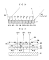
- FIG 9 is an exploded, perspective schematic of one embodiment of the reflection type color display device fabricated using such a reflection type hologram color filter 81 according to the present invention.
- a reflection type hologram color filter 81 as mentioned above is located on the back side of a transmission type spatial light modulator 85 built up of a liquid crystal display element, a polymer-dispersed type liquid crystal (PDLC) display element, etc., which is regularly divided into pixels 85', and an absorption layer 87 is positioned on the back side of the reflection type color filter 81.
- PDLC polymer-dispersed type liquid crystal
- a black matrix 86 is interposed between adjoining pixels 85' in the transmission type spatial light modulator 85.
- Three adjoining pixels 85' in the transmission type spatial light modulator 85 constitute together one color display unit 88, in which pixels B, G, and R are blue, green, and red displaying pixels, respectively.
- the elements forming the reflection type hologram color filter 81 are arranged such that these blue, green, and red displaying pixels B, G, and R in the transmission type spatial light modulator 85 correspond to the blue, green, and red reflecting filter elements 81B, 81G, and 81R in the reflection type hologram color filter 81.
- a component 82 of the ambient light that strikes thereon at a given angle of incidence passes through the pixels B, G, and R in the transmission type spatial light modulation 85 while it is subject to intensity modulation depending on their states.
- wavelength components ⁇ B , ⁇ G , and ⁇ R in the ambient light 82 are subject to intensity modulation at the same proportion for each pixel B, G, and R. Reference is here made to the light 82 that has passed through the pixels B, G, and R while it has been subject to intensity modulation.
- the light 82 which has passed through the blue-displaying pixel B strikes on the blue-reflecting filter element 81B where only a blue wavelength component ⁇ B thereof is selectively reflected, and diffracted in a given direction. Then, the thus reflected, and diffracted light passes back through the blue-displaying pixel B while it is again subject to the same modulation, so that the pixel B emits blue light 89B.
- wavelength components that are not diffracted by the filter element 81B, i.e., ⁇ G , and ⁇ R pass through the filter element 81B, and are absorbed by the absorption layer 87 mounted on the back side of the reflection type hologram color filter 81.
- the light 82 which has passed through the green-displaying pixel G while it has been subject to intensity modulation thereby, strikes on the green-reflecting filter element 81G where only a green wavelength component ⁇ G is selectively reflected, and diffracted in a given direction. Then, the thus reflected, and diffracted light passes back through the green-displaying pixel G while it is again subject to the same modulation, so that the pixel G emits green light 89G substantially in the same direction as that of the blue light 89B the pixel B emits.
- the light 82 which has passed through the red-displaying pixel R while it has been subject to intensity modulation thereby, strikes on the red-reflecting filter element 81R where only a red wavelength component ⁇ R is selectively reflected, and diffracted in a given direction. Then, the thus reflected, and diffracted light passes back through the red-displaying pixel R while it is again subject to the same modulation, so that the pixel R emits red light 89R substantially in the same direction as those of the green, and blue light 89B, and 89G the pixels B, and G emit.
- Figure 12 is a sectional schematic of one modified embodiment of the display device shown in Figure 9, which enables images to be displayed even by use of illumination by backlight.
- the embodiment of Figure 12 is similar to that of Figure 9 with the exception that an absorption filter 90 instead of the absorption layer 87 is located on the back side of the reflection type hologram color filter 81, and a backlight source 91 is positioned on the back side of the filter 90.
- This absorption filter 90 is an array comprising an absorption filter element 90G capable of transmitting only light lying in the green region or only light lying in the green, and blue regions at a position of a blue-reflecting filter element 81B in the reflection type hologram color filter 81, an absorption filter element 90R capable of transmitting only light lying in the red region or only light in the red, and green regions at a position of a green-reflecting filter element 81G, and an absorption filter element 90B capable of transmitting only light lying in the blue region or only light lying in the blue, and red regions at a position of a red-reflecting filter element 81R.
- a display device-driving circuit such that color information displayed on pixels 85' in the transmission type spatial light modulator 85 changes automatically, for instance, such that information B seen as blue when illuminated by the ambient light 82 changes automatically over to green information G when the backlight source 91 is put on, information G seen as green when illuminated by the ambient light 82 changes automatically over to red information R when the backlight source 91 is put on, and information R seen as red when illuminated by the ambient light 82 changes automatically over to blue information B when the backlight source 91 is put on.
- the backlight source 91 When the backlight source 91 is held off, therefore, it is possible to display a color image by use of illumination by the ambient light 82, as explained with reference to Figure 9.
- the pixels B, G, and R change over to G, R, and B, so that color information displayed on each pixel changes.
- white light from the backlight source 91 is reduced through the absorption filter element 90G to only light lying in the green region or only light lying in the green, and blue regions.
- the light lying in the blue region is cut by the blue-reflecting filter element 81B, so that only the light lying in the green region passes through the absorption filter 90, and the reflection type hologram color filter 81.
- the green pixel emits green light 92G because the pixel B has changed over to the pixel G.
- white light from the backlight source 91 is reduced through the absorption filter element 90R to only light lying in the red region or only light lying in the red, and green regions.
- the light lying in the green region is cut by the green-reflecting filter element 81G, so that only the light lying in the red region passes through the absorption filter 90, and the reflection type hologram color filter 81.
- the red pixel emits red light 92R because the pixel G has changed over to the pixel R.
- the blue pixel emits blue light 92B.
- the present invention is not limited to the combination, as shown in Figure 12, of the color elements of the reflection type hologram color filter 81 with the color elements of the absorption filter 90, and so other combinations may be possible.
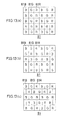
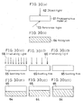
- the reflection type diffraction hologram elements 81B, 81G, and 81R in the reflection type hologram color filter 81 are two-dimensionally arranged in alignment with the pixels B, G, and R in the transmission type spatial light modulator 85 used with reflected illumination light in three basic matrix patterns as shown in Figure 13.
- the first is a matrix pattern called a striped type, as shown in Figure 13(a), wherein hologram elements B, G, and R (indicated by 81B, 81G, and 81R, respectively) appear repeatedly in each row. Notice that dotted lines given in Fig. 13(a) are not needed in actual applications.
- the second is a matrix pattern called a mosaic type, as shown in Figure 13(b), wherein the period of repetition of a set of hologram elements B, G, and R in one row is shifted by a lead or lag of 1/3 from that of a set of hologram elements B, G, and R in a row located just above.
- the third is a matrix pattern called a triangle or delta type, as shown in Figure 13(c), wherein the period of repetition of a set of hologram elements B, G, and R in one row is delayed by 1/2 from that of a set of hologram elements B, G, and R in a row located just above it.
- the striped type matrix pattern is preferred because only the one-dimensionally arranged three types of striped_holograms need be provided.
- a reflection type hologram color filter 81 comprising a two-dimensional arrangement of such reflection type hologram elements 81B, 81G, and 81R as mentioned above may be obtained by dividing one hologram photosensitive material to zones, and recording interference fringes at recording wavelengths ⁇ B , ⁇ G , and ⁇ R that vary for each zone by such a method as depicted in Figure 10(a).
- a reflection type color display device such as a color liquid crystal display device which can use ambient light to present bright displays without recourse to any backlight source by using the reflection type hologram color filter 81 in combination with the transmission type spatial light modulator 85 comprising a collection of pixels, such as a liquid crystal display device or polymer-dispersed type liquid crystal display device.
- reflection type color display device of the present invention has been described specifically with reference to some embodiments, it is understood that the present invention is not limited to these embodiments, and so various modifications may be feasible.
- a conventional absorption type of RGB color filter may be additionally used on either side of the transmission type spatial light modulator 85.
- a reflection type color display device such as a color liquid crystal display device which can use ambient light to present bright displays without recourse to any backlight source
- a reflection type hologram color filter of the present invention in combination with a transmission type spatial light modulator built up of a collection of pixels and having controllable transmittance for each pixel, the former being located on the back side of the latter.
- the hologram-recorded medium of the present invention which is applicable to the reflection type hologram 30 depicted in Figure 8, and the reflection type hologram color filter 81 depicted in Figure 9, and the principles and embodiments of fabricating the same will then be explained with reference to the drawings.
- Figure 14 illustrates an exemplified structure of the hologram-recorded medium of the present invention.
- Figure 14(a) is a general plan view of the hologram-recorded medium shown at 101
- Figure 14(b) is an enlarged view of an encircled small area in the hologram-recorded medium 101 shown in Figure 14(a)
- Figure 14(c) is a sectional view taken along the line C-C' in Figure 14(b).
- the hologram-recorded medium 101 comprises a volume (Lippmann) type hologram photosensitive material such as a photopolymer, and has a desired color pattern formed thereon, as shown in Figure 14(a).
- This color pattern is a full-color pattern, and develops colors for the reasons mentioned later.
- a plurality of color patterns may have been formed on the photosensitive material so that they can be seen in varying patterns depending on a viewing direction.
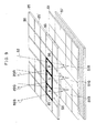
- the hologram-recorded medium 101 has its recorded area divided regularly into a micro-dot form of pixels 102.
- the pixels are arranged in a gridiron pattern, but may not necessarily be limited to this pattern.
- the pixels may be in a piled pattern.
- One pixel 102 may be not only quadrangular but also circular, triangular or hexagonal in shape.
- each pixel 102 there is recorded a volume type of interference fringe 103, as shown sctionally in Figure 14(c).
- the interference fringes 103 usually comprise a spatial alternation of plane high, and low refractive index zones, which are arranged parallel at a constant pitch. Such interference fringes will hereinafter be called a Bragg grating 103.
- four adjoining pixels 102 1 to 102 4 are depicted for the purpose of illustrating schematically some possible configurations that the pixels 102 can have as the Bragg grating 103.
- the pixels 102 1 and 102 2 have each the Bragg grating 103 formed parallel with the recording surface, but they are different from each other in terms of pitch (grating spacing).
- pitch grating spacing
- the wavelengths diffracted by the pixel 102 1 , the pixel 102 2 , and a pixel (not shown) in which the Bragg grating 103 differing in pitch from those of the pixels 102 1 , and 102 2 is likewise formed parallel on the recording surfaced are assigned to blue, green, and red regions, respectively, it is then possible to record a color pattern of the three primary colors R, G, and B depending on how the pixels 102 are combined. Notice that how to select color tone, and gradation will be described later.
- the pixels 102 3 and 102 4 are identical in terms of grating spacing, but differ in terms of the inclination of grating surface (fringe surface).
- the angle of inclination, and the direction of grating surface can be freely selected. Incident light is diffracted by the Bragg grating 103 in a direction in which the angle of incidence, and the angle of diffraction are equal to each other with respect to the grating surface.
- the pixels 102 3 , and 102 4 cannot simultaneously be observed in the same color when the direction of illumination is specified.
- the pixels 102 3 , and 102 4 can selectively be observed depending on a viewing direction.
- one Bragg grating 103 satisfies the Bragg condition at a different wavelength when the angle of incidence varies, one pixel 102 3 or 102 4 changes color depending on a viewing direction if white light for illumination diffuses in the illumination direction.
- R, G, and B dot areas, and their dot percent may be varied to vary gradation, and color tone, as in the case of printing.
- R, G, and B dots may be obtained by two methods, i.e., by dividing a single pixel into three parts, and by associating a set of adjoining three pixels with dots R, G, and B. Both methods are essentially identical with each other.
- Figure 15 illustrates a typical area gradation method wherein color tone is varied by varying dot percent.
- Figure 15(a) illustrates the case where the dot percent between a red dot 104R having interference fringes 103 recorded therein to express R, a green dot 104G having interference fringes 103 recorded therein to express G, and a blue dot 104B having interference fringes 103 recorded therein to express B is 1:1:1 so that they are seen as white by additive color mixing. If, as depicted in Figure 15(b), the areas of the red, and blue dots 104R, and 104B are reduced with a corresponding increase in the area of the green dot 104G, these dots are then seen as green.
- the green color is more enhanced in gradation. It is thus possible to express any desired color tone with any desired gradation by controlling the dot percent between the red, green, and blue dots 104R, 104G, and 104B.
- Figure 16 illustrates another dot area gradation method wherein dot percent is again varied to vary color tone.
- red, green, and blue dots 104R, 104G, and 104B with their dot percent being 1:1:1 as depicted in Figure 16(a), the areas of the red, and blue dots 104R, and 104B are reduced by the interposition of blanks 105, so that the area of the green dot 104G increases relatively.
- the larger the area of the green dot 10G the more enhanced the green color is in gradation.
- This method is similar to an ordinary color printing method, and makes it possible to express any desired color tone with any desired gradation by controlling the dot percent between the red, green, and blue dots 104R, 104G, and 104B.
- Figure 17 illustrates a density, not area, gradation method wherein the diffraction efficiency of interference fringes 103 is regulated to any desired value when recording the interference fringes 103, thereby controlling color tone, and gradation.
- the dot percent between a red dot 104R having interference fringes 103 recorded therein to express R, a green dot 104G having interference fringes 103 recorded therein to express G, and a blue dot 104B having interference fringes 103 recorded therein to express B remains fixed at 1:1:1, and in the case of Figure 17(a), the diffraction efficiencies of the dots 104R, 104G, and 104B are all set at 100%, so that they are seen as white by additive color mixing.
- the aforesaid area, and density gradation methods may be used in combination. It is here noted that the embodiment depicted in Figure 17 may be modified such that interference fringes 103 for expressing red, green, and blue are recorded in one pixel in a superposed manner with controlled diffraction efficiencies of the interference fringes 103, so that any desired color tone can be expressed with any desired gradation.
- the medium is fabricated from a computer-generated hologram (CGH) by replication
- the second wherein the medium is fabricated by use of a mask pattern, and an inclined plane mirror
- the third wherein the medium is fabricated by use of a group of micro-mirrors that vary in reflection direction per position
- the four wherein the medium is fabricated by recording the Bragg grating while two coherent light beams are moved relatively with respect to a hologram-recording medium.
- a CGH of the relief type is in itself fabricated by using a computer to calculate interference fringes (a diffraction grating) which diffract light of given wavelength with respect to a given zone alone in a given direction, and drawing the interference fringes on a glass or other substrate with an electron beam resist coated thereon by use of an electron beam, for instance, followed by development.
- interference fringes a diffraction grating
- CGHs of the reflection or transmission type too, may be fabricated.
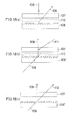
- a volume hologram photosensitive material 107 such as a photopolymer is stacked on a reflection type CGH 106, and reconstructing illumination light 108 of given wavelength is then allowed to strike on the CGH 106 through the hologram photosensitive material 107, as shown in Figure 18(a).
- first-order diffracted light 109 is diffracted from the CGH 106 in the opposite direction, and then interferes with the incident light 108 to produce interference fringes, which are in turn recorded in the photosensitive material 107.
- a dichroic filter 110 comprising a multilayer interference film and capable of cutting higher-order diffracted light striking on the CGH 106 at angles different from those of the incident light 108, and first-order diffracted light 109 may be interposed between the CGH 106 and the hologram photosensitive material 107 to prevent unnecessary interference fringes from being recorded therein.
- a volume hologram photo-sensitive material 107 such as a photopolymer is stacked on a transmission type CGH 106', and reconstructing illumination light 108 of given wavelength is then allowed to strike on the side of the CGH 106' that is not opposite to the hologram material 107, as depicted in Figure 18(b).
- first-order diffracted light 109 is diffracted from the CGH 106' in the opposite direction.
- reference light 111 is allowed to strike on the photosensitive material 107, so that the first-order diffracted light 109, and reference light 111 interfere in the hologram photosensitive material 107 to record interference fringes therein.
- a dichroic filter 110 capable of cutting zero-order light, and higher-order diffracted light striking on the CGH 106' at an angle different from that of the first-order diffracted light 109 may be interposed between the CGH 106' and the hologram photosensitive material 107 to prevent unnecessary interference fringes from being recorded therein.
- a volume hologram photosensitive material 107 such as a photopolymer is stacked on a transmission type CGH 106', and reconstructing illumination light 108 of given wavelength is then allowed to strike on the side of the CGH 106' that is not opposite to the hologram material 107, as depicted in Figure 18(c).
- first-order diffracted light 109 is diffracted from the CGH 106' in the opposite direction, and zero-order light 112 goes straightforward, so that both light 109 and 112 strike on the hologram photosensitive material 107 from the same direction to record a transmission type of volume interference fringes 103 therein.
- a hologram-recorded medium of the present invention which has a plurality of patterns recorded therein, said patterns comprising a group of pixels with the same volume type interference fringes 103 recorded therein.
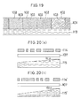
- the recorded volume hologram is of the transmission type, the recorded patterns cannot be seen from the illumination side. Accordingly, as shown sectionally in Figure 19, a reflecting layer 113 such as an aluminum layer must be provided on the back side of the hologram-recorded medium 101 to let it be of the reflection type.
- a plurality of mask plates 114 and 114' are fabricated, which have different patterns of openings to be recorded, as depicted in Figure 20.
- plane mirrors 115 and 115' having different angles of inclination ⁇ 1 and ⁇ 2 are provided.
- one plane mirror may be used to alter the angle of inclination between ⁇ 1 and ⁇ 2 .
- a volume hologram photosensitive material 107 is interposed between the mask plate 114 and the plane mirror 115 such that they are positioned in proximity to one another.
- the incident light, and light reflected by the plane mirror 115 and tilting dependent on the angle of inclination ⁇ 1 interfere in the material 107 to record interference fringes therein.
- another mask plate 114' having a different opening pattern is located with the hologram photosensitive material 107 and the plane mirror 115' such that they are positioned in proximity to one another, thereby recording a different type of interference fringes in the same volume hologram photosensitive material 107.
- a hologram-recorded medium of the invention which has a plurality of patterns recorded therein, said patterns comprising a group of pixels with the same volume hologram photosensitive material 107.
- it is also effective to use primaries-separating original patterns obtained in the color separation step for printing as the mask plates 114 and 114'.
- a plurality of off-axis reflection type holograms 123 are provided, which diffract an almost vertically incident light beam 121 at an angle ⁇ into diffracted light 122 propagating in the reflection direction, and have different angles ⁇ .
- a volume hologram photosensitive material 107 is interposed between a mask plate 114 and the off-axis reflection type hologram 123 such that they are positioned in proximity to one another, and the whole of the volume hologram photosensitive material 107 is illuminated by the light 121 through the openings in the mask plate 114 to record one interference fringe therein.
- a hologram-recorded medium of the present invention which has a plurality of patterns recorded therein, said patterns comprising a group of pixels with the same volume type interference fringes 103 recorded therein.
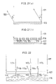
- a composite reflector 116 which comprises a collection of micro-mirrors 116' varying in reflection direction per position, as depicted in Figure 22.
- a volume hologram photosensitive material 107 is positioned in proximity to the surface of the reflector 116. Then, a light beam 117 is permitted to strike on the hologram photosensitive material 107, whereupon the light beam 117 passes through the hologram photosensitive material 107, and is reflected at micro-mirror surfaces 116' 1 , 116' 2 , and 116' 3 into reflected light 118 1 , 118 2 , and 118 3 , which propagate in different directions.
- the reflected light 118 1 , 118 2 , and 118 3 and the incident light 117 1 , 117 2 , and 117 3 interfere in the hologram photosensitive material 107 to record interference fringes varying per position therein.
- a desired pattern is expressed by a group of the micro-mirror surfaces 116' having the same reflection direction, therefore, it is possible to obtain a hologram-recorded medium of the present invention which has a plurality of patterns recorded therein, said patterns comprising a group of pixels with the same volume type interference fringes 103 recorded therein. It is understood that different composite reflectors 116 may be used to record interference fringes in one hologram photo-sensitive material 107 in a superposed manner.
- an off-axis reflection type micro-holograms 123 varying in diffraction direction per position such as those shown in Figure 21(a) may be used in place of the micro-mirror surfaces 116' varying in reflection direction per position.
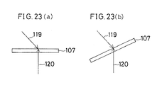
- two coherent thin light beams 119 and 120 intersect each other at a given relative angle in a specific pixel position in a volume hologram photosensitive material 107 positioned at a certain angle, thereby recording in that pixel position a volume type interference fringe 103 derived from the conditions for aligning these parts, as depicted in Figure 23(a).
- another volume type interference fringe 103 derived from the conditions for setting the angle of the hologram photosensitive material 107 and/or the relative angles of the light beams 119 and 120 which are different from those mentioned above is recorded in the hologram photosensitive material.
- This process is sequentially carried out for all pixel positions where the interference fringes 103 are recorded until a hologram-recorded medium of the present invention is finally obtained, which has a plurality of patterns recorded therein, said patterns comprising a group of pixels with the same volume type interference fringes 103 recorded therein.
- hologram-recorded medium of the present invention and the method of fabricating the same have been described with reference to several embodiments, it is understood that the present invention is not limited thereto, and so various modifications may be feasible.
- interference fringes obtained by the interference of diffused light and parallel light as typically depicted in Figure 1, are used as the interference fringes 103 to be recorded in the pixels 102 1 to 102 4 , it is then possible to obtain color pixels 102 1 to 102 4 of the diffuse reflection type.
- Such a hologram-recorded medium lends itself well fit to the reflection type hologram 30 depicted in Figure 8, and the reflection type hologram color filter 81 depicted in Figure 9.
- a hologram-recorded medium having high diffraction efficiency and capable of reconstructing a bright pattern because it is a medium which has an imagewise or other pattern comprising a collection of pixels, and in which any one of a volume type of different diffracting gratings comprising volume holograms is assigned to at least a part of the pixels. It is also possible to record a multiplex pattern with no drop of diffraction efficiency. Further, it is possible to record, and reconstruct, a full-color pattern while color tone, and gradation are placed under control by additive color mixing. Furthermore, it is possible to record, and reconstruct, different patterns which are sharply changeable depending on a viewing direction, and an illumination direction.
- this hologram color display medium two swelling films obtained by mixing a monomer or oligomer, a photopolymerization initiator, etc. with a binder polymer are provided, as in the case of a photopolymer.
- a given area of each swelling film is irradiated with light in a quantity sufficient to deactivate the swelling agent (monomer or oligomer) contained in that area while the other area of the film is not irradiated with light to keep the swelling agent in an active state.
- the active swelling agent is diffused from the selected areas of the swelling films into the photosensitive material through both its sides, and fixed in place, thereby arbitrarily forming three or four zones, a first zone where the swelling agent is diffused from both sides of the material, a second zone where the swelling agent is diffused from one side of the material, a third zone where the swelling agent is diffused from the other side of the material, and a fourth zone where the swelling agent is not diffused from either side of the material at all, so that three or four fringe spacings are available to reconstruct a given three- or four-color pattern.
- Figure 24 illustrates the principle of a first embodiment of the hologram color display medium of the invention.
- Figure 24(a) is a plan view of a swelling film 131 to be in close contact with the surface side of the material
- Figure 24(b) is a plan view of a swelling film 132 to be in close contact with the back side of the material.
- Each film may have been obtained by mixing a monomer or oligomer, a photopolymerization initiator, etc. with a binder polymer, as in the case of a photopolymer.
- an area 131n occupying the right 2/3 of the swelling film 131 to be into close contact with the surface side of the material, and an area 132n occupying the right 1/3 of the swelling film 132 to be into close contact with the back side of the material have been deactivated by exposure to light in a quantity sufficient to make inert substantially all of the penetrating active monomer or oligomer in the swelling films.
- the swelling film 131 is active in an area 131a occupying the left 1/3 thereof, while the swelling film 132 is active in an area 132a occupying the left 2/3 thereof.
- a volume hologram 130 comprising plane interference fringes at a constant pitch is recorded in a photopolymer or other photosensitive material, as in the case of Figure 29(a).
- the swelling films 131, and 132 with some areas deactivated according to a certain deactivation pattern as depicted in Figures 24(a), and 24(b) are brought into close contact with the surface, and back sides of the material, as depicted sectionally in Figure 24(c).
- the stack is heated under temperature, and time conditions sufficient to diffuse the penetrating active monomer or oligomer from the swelling films 131, and 132 into the volume hologram 130.
- a volume hologram 140 after subjected to the swelling treatment are divided into three areas depending on the degree of swelling, as depicted in Figure 24(d), i.e., an area A swollen by the swelling agent diffused from both swelling films 131 and 132, an area B swollen by the swelling agent diffused from the swelling film 132, and an area C not subjected to swelling at all.
- the degree of swelling is area A > area B > area C. If, for instance, the volume hologram 130 is illuminated by light of blue wavelength, the area C does not substantially swell to diffract, and reproduce the blue light in a given direction.
- the area B having a medium degree of swelling diffracts, and reproduces green light longer in wavelength than blue light in the same direction.
- the area A having the largest degree of swelling diffracts, and reproduces red light longer in wavelength than green light in the same direction. It is thus possible to record any desired two- or three-color pattern by the simultaneous swelling of the swelling films 131 and 132 with some areas deactivated according to a given deactivation pattern, which are brought into close contact with both sides of the volume hologram 130.
- Figure 25 illustrates the principle of a second embodiment of the hologram color display medium of the present invention.
- Figure 25(a) is a plan view of a swelling film 131 which is to be first brought into close contact with the surface side of the material for swelling. An area 131n occupying the right 1/2 of the swelling film 131 has been deactivated by exposure to light, as in the case of Figure 24.
- the swelling film 131 with the area 131n deactivated according to a constant deactivation pattern as depicted in Figure 25(a) is brought into close contact with the surface of a volume hologram 130 previously obtained by recording plane interference fringes in a photopolymer or other photosensitive material at a constant pitch.
- the stack is heated under temperature, and time conditions sufficient to diffuse the penetrating active monomer or oligomer from the swelling film 131 into the volume hologram 130.
- Another swelling film 132 such as one shown in Figure 25(c) is provided, which is to be brought into close contact with the back side of the material.
- An area 132n occupying the central 1/2 of the film 132 has been deactivated by exposure to light, as in the case of Figure 24, except areas 132a, and 132a occupying the left, and right 1/4 of the film 132.
- the swelling film 132 with the area 132n deactivated according to a constant deactivation pattern as depicted in Figure 25(c) is brought into close contact with the back side of the volume hologram 130, as depicted in Figure 25(d).
- the stack is heated under temperature, and time conditions sufficient to diffuse the penetrating active monomer or oligomer from the swelling films 132 into the volume hologram 130.
- a volume hologram 140 after subjected to the swelling treatment are divided into four areas depending on the degree of swelling, as depicted in Figure 25(e), i.e., an area A swollen by the swelling agent diffused from both swelling films 131 and 132, an area B swollen by the swelling agent diffused from the swelling film 131 provided on the surface side of the material, and subject to enhanced swelling by heating for the swelling treatment of the back side of the material, an area D swollen by the swelling agent diffused from the swelling film 132 provided on the back side of the material, and an area C not subjected to swelling at all.
- the degree of swelling is area A > area B > area D > area C. If, for instance, the volume hologram 130 is illuminated by light of blue wavelength, the area C does not substantially swell to diffract, and reproduce blue light in a given direction.
- the area D having some degree of swelling diffracts, and reproduces bluish green light longer in wavelength than blue light in the same direction.
- the area B larger in the degree of swelling than the area D diffracts, and reproduces green light longer in wavelength than bluish green light in the same direction.
- the area A having the largest degree of swelling diffracts, and reproduces red light longer in wavelength than green light in the same direction. It is thus possible to record any desired three- or four-color pattern by the successive swelling of the swelling films 131, and 132 with some areas deactivated according to a given deactivation pattern, which are brought into close contact with both sides of the volume hologram 130.
- the deactivation of the given areas of the swelling films 131, and 132 is carried out by exposure to ultraviolet or other light of given wavelength before the close contact thereof with the volume hologram 130.
- the swelling films 131, and 132 may be deactivated after such close contact.
- the deactivation of the swelling film 131 or 132 results in the deactivation of the other film 132 or 131 in the same pattern.
- the swelling films 131 and 132 different in wavelength selectivity from each other. It is thus preferable that the swelling film 131 is deactivated by light of wavelength coincident with the sensitivity thereof, and that the swelling film 132 is deactivated by light of another wavelength coincident with the sensitivity thereof.
- Patterns obtained with the aforesaid methods are only three- or four-color patterns.
- any desired color can be expressed by varying the dot percent of the pixels A, B, C, and D on the assumption that the color display unit has a constant area.
- the first method involves recording in the volume hologram 130 interference fringes having uniform fringe spacings such that their diffraction efficiency varies depending on the positions of the aforesaid color display units, not interference fringes having uniform diffraction efficiency (refractive index modulation). Notice that the interference fringes have a constant spacing between adjoining fringes, and are each in a plane form, with the refractive index modulation varying per position.
- the volume hologram 130 used may be of a halftone-including absorption type, or may be provided on its diffraction side with a layer such that the intensity of diffracted light varies depending on the position of the aforesaid color display units.
- the volume hologram 130 is provided on its surface with a layer with a halftone-including white-and-black image such as a white-and-black photograph negative recorded therein, or the medium of volume hologram 130 used is of an absorption type such that the intensity of diffracted light varies depending on position.
- the degree of deactivation of the swelling films 131 and 132 may be regulated to different values by controlling the quantity of irradiating light, thereby regulating the degree of swelling.
- plane interference fringes have been recorded in the volume hologram 130 at a constant pitch.
- color areas A to D of the diffuse reflection type can be obtained by recording interference fringes produced by the interference of diffused light and parallel light, as typically shown in Figure 1.
- Such a hologram color display medium is suitable for use on the reflection type hologram 30 depicted in Figure 8, and the reflection type hologram color filter 81 depicted in Figure 9.
- a stable pattern of two or more different colors can be reproduced by swelling from a hologram with uniform interference fringes recorded therein without recourse to light quantity control, because the hologram is swollen from both its sides using two swelling films irradiated with a given or more quantity of light according to the deactivation pattern.
- a two-dimensional diffraction pattern of two or more colors can be displayed by the combination of the deactivated pattern of one swelling film with that of another swelling film.
Landscapes
- Physics & Mathematics (AREA)
- General Physics & Mathematics (AREA)
- Optics & Photonics (AREA)
- Nonlinear Science (AREA)
- Mathematical Physics (AREA)
- Chemical & Material Sciences (AREA)
- Crystallography & Structural Chemistry (AREA)
- Liquid Crystal (AREA)
- Diffracting Gratings Or Hologram Optical Elements (AREA)
- Holo Graphy (AREA)
- Optical Elements Other Than Lenses (AREA)
Priority Applications (2)
| Application Number | Priority Date | Filing Date | Title |
|---|---|---|---|
| EP10171609A EP2254002A1 (de) | 1996-07-22 | 1997-07-22 | Mit Hologrammen beschriebenes Medium und Verfahren zu dessen Herstellung |
| EP10171598A EP2254001B1 (de) | 1996-07-22 | 1997-07-22 | Reflektive Farbanzeigevorrichtung mit Reflexionshologrammfarbfilter |
Applications Claiming Priority (3)
| Application Number | Priority Date | Filing Date | Title |
|---|---|---|---|
| JP19202096A JP3781214B2 (ja) | 1996-07-22 | 1996-07-22 | ホログラムカラー表示媒体及びその作製方法 |
| JP19757496A JP3888648B2 (ja) | 1996-07-26 | 1996-07-26 | 反射型カラー表示装置 |
| EP97112512A EP0821293B1 (de) | 1996-07-22 | 1997-07-22 | Farbiges Hologramm-Anzeigemedium und Verfahren zu dessen Herstellung |
Related Parent Applications (2)
| Application Number | Title | Priority Date | Filing Date |
|---|---|---|---|
| EP97112512A Division EP0821293B1 (de) | 1996-07-22 | 1997-07-22 | Farbiges Hologramm-Anzeigemedium und Verfahren zu dessen Herstellung |
| EP97112512.5 Division | 1997-07-22 |
Related Child Applications (2)
| Application Number | Title | Priority Date | Filing Date |
|---|---|---|---|
| EP10171609.0 Division-Into | 2010-08-02 | ||
| EP10171598.5 Division-Into | 2010-08-02 |
Publications (3)
| Publication Number | Publication Date |
|---|---|
| EP1801666A2 true EP1801666A2 (de) | 2007-06-27 |
| EP1801666A3 EP1801666A3 (de) | 2007-11-21 |
| EP1801666B1 EP1801666B1 (de) | 2011-06-15 |
Family
ID=26507046
Family Applications (4)
| Application Number | Title | Priority Date | Filing Date |
|---|---|---|---|
| EP10171609A Withdrawn EP2254002A1 (de) | 1996-07-22 | 1997-07-22 | Mit Hologrammen beschriebenes Medium und Verfahren zu dessen Herstellung |
| EP10171598A Expired - Lifetime EP2254001B1 (de) | 1996-07-22 | 1997-07-22 | Reflektive Farbanzeigevorrichtung mit Reflexionshologrammfarbfilter |
| EP07102044A Expired - Lifetime EP1801666B1 (de) | 1996-07-22 | 1997-07-22 | Reflexionshologrammfarbfilter verwendende reflektive Anzeigevorrichtung |
| EP97112512A Expired - Lifetime EP0821293B1 (de) | 1996-07-22 | 1997-07-22 | Farbiges Hologramm-Anzeigemedium und Verfahren zu dessen Herstellung |
Family Applications Before (2)
| Application Number | Title | Priority Date | Filing Date |
|---|---|---|---|
| EP10171609A Withdrawn EP2254002A1 (de) | 1996-07-22 | 1997-07-22 | Mit Hologrammen beschriebenes Medium und Verfahren zu dessen Herstellung |
| EP10171598A Expired - Lifetime EP2254001B1 (de) | 1996-07-22 | 1997-07-22 | Reflektive Farbanzeigevorrichtung mit Reflexionshologrammfarbfilter |
Family Applications After (1)
| Application Number | Title | Priority Date | Filing Date |
|---|---|---|---|
| EP97112512A Expired - Lifetime EP0821293B1 (de) | 1996-07-22 | 1997-07-22 | Farbiges Hologramm-Anzeigemedium und Verfahren zu dessen Herstellung |
Country Status (1)
| Country | Link |
|---|---|
| EP (4) | EP2254002A1 (de) |
Cited By (2)
| Publication number | Priority date | Publication date | Assignee | Title |
|---|---|---|---|---|
| DE19748967B4 (de) * | 1997-11-06 | 2009-04-02 | Bundesdruckerei Gmbh | Verfahren und Vorrichtung zur Herstellung eines variablen Sicherheitshologramms |
| WO2011113662A1 (fr) * | 2010-03-17 | 2011-09-22 | Delphi Technologies, Inc. | Combineur diffractif pour dispositif d'affichage tête haute couleur |
Families Citing this family (26)
| Publication number | Priority date | Publication date | Assignee | Title |
|---|---|---|---|---|
| EP0886802B1 (de) | 1996-03-15 | 2001-11-21 | Retinal Display Cayman Ltd. | Verfahren und vorrichtung zur betrachtung eines bildes |
| EP0828203A3 (de) * | 1996-09-09 | 1998-09-09 | Dai Nippon Printing Co., Ltd. | Struktur zur Aufnahme eines Mehrfarbenhologramms |
| DE19806851A1 (de) * | 1998-02-19 | 1999-09-16 | Heraeus Noblelight Gmbh | Verfahren zur Einkoppelung von Strahlung mittels holographischer Filter, sowie Vorrichtung und Verwendung |
| EP1114340A1 (de) | 1998-09-14 | 2001-07-11 | Digilens Inc. | Holographisches beleuchtungssystem und holographisches projektionssystem |
| WO2000024204A1 (en) | 1998-10-16 | 2000-04-27 | Digilens, Inc. | Method and system for display resolution multiplication |
| WO2000023835A1 (en) * | 1998-10-16 | 2000-04-27 | Digilens, Inc. | Holographic technique for illumination of image displays using ambient illumination |
| FI106323B (fi) * | 1998-12-30 | 2001-01-15 | Nokia Mobile Phones Ltd | Taustavalaistuksen valonjohdin litteälle näytölle |
| US6678078B1 (en) | 1999-01-07 | 2004-01-13 | Digilens, Inc. | Optical filter employing holographic optical elements and image generating system incorporating the optical filter |
| US6504629B1 (en) | 1999-03-23 | 2003-01-07 | Digilens, Inc. | Method and apparatus for illuminating a display |
| US6507419B1 (en) | 1999-03-23 | 2003-01-14 | Digilens, Inc. | Illumination system using optical feedback |
| FI107085B (fi) * | 1999-05-28 | 2001-05-31 | Ics Intelligent Control System | Valopaneeli |
| US6424437B1 (en) | 2000-10-10 | 2002-07-23 | Digilens, Inc. | Projection display employing switchable holographic optical elements |
| GB0030675D0 (en) * | 2000-12-15 | 2001-01-31 | Rue De Int Ltd | Methods of creating high efficiency diffuse back-reflectors based on embossed surface relief |
| US6646771B2 (en) * | 2000-12-21 | 2003-11-11 | E. I. Du Pont De Nemours And Company | Method for producing holographic optical element comprising primary and complementary holograms and associated methods for establishing authenticity of element used as security device |
| KR100442820B1 (ko) * | 2001-05-04 | 2004-08-02 | 삼성전자주식회사 | 큰 입사각을 갖는 홀로그램 기록방법 및 홀로그래픽리플렉터를 이용한 홀로그램 재생장치 및 이를 이용한재생방법 및 홀로그래픽 리플렉터를 이용한평면표시소자장치 |
| WO2002101428A1 (en) * | 2001-06-11 | 2002-12-19 | Aprilis, Inc. | Holographic filter with a wide angular field of view and a narrow spectral bandwidth |
| GB2432224A (en) * | 2005-11-15 | 2007-05-16 | Technical Dev & Invest Ltd | Apparatus and method for producing a volume reflection hologram |
| DE102007022109A1 (de) * | 2007-05-11 | 2008-11-13 | Prüfbau Dr.-Ing. H. Dürner GmbH | Vorrichtung zum Erzeugen eines Reflexionshologramms hoher Auflösung |
| DE102007023560B4 (de) | 2007-05-21 | 2009-02-05 | Ovd Kinegram Ag | Mehrschichtkörper |
| US20100238529A1 (en) * | 2009-03-23 | 2010-09-23 | Qualcomm Mems Technologies, Inc. | Dithered holographic frontlight |
| WO2012033178A1 (ja) | 2010-09-08 | 2012-03-15 | 大日本印刷株式会社 | 照明装置、投射装置および投射型映像表示装置 |
| CN106406061B (zh) * | 2016-11-16 | 2021-11-19 | 苏州苏大维格科技集团股份有限公司 | 一种体全息元件制作方法 |
| CN111722512A (zh) * | 2019-03-20 | 2020-09-29 | 南昌欧菲光科技有限公司 | 全息图纹膜的制作方法及终端 |
| CN113050283B (zh) * | 2021-03-18 | 2022-07-22 | 歌尔股份有限公司 | 光线偏转结构和头戴显示设备 |
| WO2023117562A1 (en) | 2021-12-22 | 2023-06-29 | Covestro Llc | Method for producing volume reflection holograms with substrate-guided reconstruction beams and/or substrate-guided diffracted beams in a single-beam set-up |
| EP4202560A1 (de) * | 2021-12-22 | 2023-06-28 | Covestro Deutschland AG | Verfahren zur herstellung von volumenreflexionshologrammen mit substratgeführten rekonstruktionsstrahlen und/oder substratgeführten beugungsstrahlen in einem einzelstrahlaufbau |
Citations (5)
| Publication number | Priority date | Publication date | Assignee | Title |
|---|---|---|---|---|
| US3758186A (en) * | 1966-11-30 | 1973-09-11 | Battelle Development Corp | Method of copying holograms |
| US5267060A (en) * | 1990-09-28 | 1993-11-30 | Rockwell International Corporation | Reflective color light filter and method of manufacture |
| WO1995012826A1 (en) * | 1993-11-01 | 1995-05-11 | Motorola Inc. | Liquid crystal display device comprising reflective holographic optical element |
| WO1995034834A1 (en) * | 1994-06-10 | 1995-12-21 | E.I. Du Pont De Nemours And Company | Holographic multicolor optical elements for use in liquid crystal displays and methods of making the elements |
| US5506701A (en) * | 1993-01-28 | 1996-04-09 | Dai Nippon Printing Co., Ltd. | Hologram color filter, liquid crystal display device using the same, and fabrication process of hologram color filter |
Family Cites Families (6)
| Publication number | Priority date | Publication date | Assignee | Title |
|---|---|---|---|---|
| JPH0512170A (ja) | 1991-07-02 | 1993-01-22 | Nec Corp | 入出力制御方式 |
| US5182180A (en) * | 1991-08-27 | 1993-01-26 | E. I. Du Pont De Nemours And Company | Dry film process for altering the wavelength of response of holograms |
| JPH05120016A (ja) | 1991-10-25 | 1993-05-18 | Fujitsu Ltd | 並列論理型言語の実行方法 |
| US5526145A (en) * | 1994-06-10 | 1996-06-11 | E. I. Du Pont De Nemours And Company | Color tuned holographic optical elements and methods of making and using the elements |
| JPH08123300A (ja) * | 1994-10-18 | 1996-05-17 | Dainippon Printing Co Ltd | 反射型拡散性ホログラムとその製造方法 |
| JP2789307B2 (ja) | 1995-01-13 | 1998-08-20 | 松雄 相澤 | 穀物乾燥機用除塵機 |
-
1997
- 1997-07-22 EP EP10171609A patent/EP2254002A1/de not_active Withdrawn
- 1997-07-22 EP EP10171598A patent/EP2254001B1/de not_active Expired - Lifetime
- 1997-07-22 EP EP07102044A patent/EP1801666B1/de not_active Expired - Lifetime
- 1997-07-22 EP EP97112512A patent/EP0821293B1/de not_active Expired - Lifetime
Patent Citations (5)
| Publication number | Priority date | Publication date | Assignee | Title |
|---|---|---|---|---|
| US3758186A (en) * | 1966-11-30 | 1973-09-11 | Battelle Development Corp | Method of copying holograms |
| US5267060A (en) * | 1990-09-28 | 1993-11-30 | Rockwell International Corporation | Reflective color light filter and method of manufacture |
| US5506701A (en) * | 1993-01-28 | 1996-04-09 | Dai Nippon Printing Co., Ltd. | Hologram color filter, liquid crystal display device using the same, and fabrication process of hologram color filter |
| WO1995012826A1 (en) * | 1993-11-01 | 1995-05-11 | Motorola Inc. | Liquid crystal display device comprising reflective holographic optical element |
| WO1995034834A1 (en) * | 1994-06-10 | 1995-12-21 | E.I. Du Pont De Nemours And Company | Holographic multicolor optical elements for use in liquid crystal displays and methods of making the elements |
Cited By (3)
| Publication number | Priority date | Publication date | Assignee | Title |
|---|---|---|---|---|
| DE19748967B4 (de) * | 1997-11-06 | 2009-04-02 | Bundesdruckerei Gmbh | Verfahren und Vorrichtung zur Herstellung eines variablen Sicherheitshologramms |
| WO2011113662A1 (fr) * | 2010-03-17 | 2011-09-22 | Delphi Technologies, Inc. | Combineur diffractif pour dispositif d'affichage tête haute couleur |
| FR2957683A1 (fr) * | 2010-03-17 | 2011-09-23 | Delphi Tech Inc | Combineur diffractif pour afficheur tete haute couleur |
Also Published As
| Publication number | Publication date |
|---|---|
| EP0821293A2 (de) | 1998-01-28 |
| EP0821293A3 (de) | 1998-11-18 |
| EP2254001A1 (de) | 2010-11-24 |
| EP0821293B1 (de) | 2011-06-08 |
| EP1801666B1 (de) | 2011-06-15 |
| EP1801666A3 (de) | 2007-11-21 |
| EP2254002A1 (de) | 2010-11-24 |
| EP2254001B1 (de) | 2012-02-08 |
Similar Documents
| Publication | Publication Date | Title |
|---|---|---|
| US6667819B2 (en) | Reflection type diffuse hologram, hologram for reflection hologram color filters, etc., and reflection type display device using such holograms | |
| EP1801666B1 (de) | Reflexionshologrammfarbfilter verwendende reflektive Anzeigevorrichtung | |
| US5506701A (en) | Hologram color filter, liquid crystal display device using the same, and fabrication process of hologram color filter | |
| US6366369B2 (en) | Transmission hologram fabrication process | |
| EP0752600B1 (de) | Holographisches Farbfilter und sein Herstellungsverfahren | |
| US20030020975A1 (en) | Holographic light panels and flat panel display systems and method and apparatus for making same | |
| US20110122467A1 (en) | Light modulating device | |
| US20020003637A1 (en) | Method for alignment of a hologram with an associated substrate | |
| US6081354A (en) | Holographic reflector for liquid crystal display | |
| US20020001110A1 (en) | Holographic light panels and flat panel display systems and method and apparatus for making same | |
| US6762810B2 (en) | Liquid crystal display device using a hologram, hologram scatter plate, and process of replicating a diffuse reflection type hologram | |
| JP4172603B2 (ja) | 反射型液晶表示装置用回折型拡散反射板 | |
| JP3969607B2 (ja) | 多色ホログラム記録体 | |
| EP0828203A2 (de) | Struktur zur Aufnahme eines Mehrfarbenhologramms | |
| JP4297382B2 (ja) | 多色ホログラム記録体の製造方法 | |
| JP3608391B2 (ja) | ホログラフィック拡散シートとそれを用いた反射型液晶表示装置 | |
| JP3888648B2 (ja) | 反射型カラー表示装置 | |
| JPH09281477A (ja) | ホログラムカラーフィルターを用いた反射型直視カラー表示装置 | |
| JP4232918B2 (ja) | 拡散反射型ホログラフィック光学部材 | |
| JPH11305677A (ja) | 反射型液晶表示装置 | |
| Petrova et al. | Basic holographic characteristics of a panchromatic light sensitive material for reflective autostereoscopic 3D display | |
| JP3907088B2 (ja) | 白色ホログラム表示体 | |
| KR20230009318A (ko) | 디스플레이 장치 및 이의 포토마스크 | |
| JPH08190092A (ja) | ホログラムカラーフィルターを用いた液晶投影表示装置 | |
| JPH0990860A (ja) | ホログラムアレーの複製方法 |
Legal Events
| Date | Code | Title | Description |
|---|---|---|---|
| PUAI | Public reference made under article 153(3) epc to a published international application that has entered the european phase |
Free format text: ORIGINAL CODE: 0009012 |
|
| AC | Divisional application: reference to earlier application |
Ref document number: 0821293 Country of ref document: EP Kind code of ref document: P |
|
| AK | Designated contracting states |
Kind code of ref document: A2 Designated state(s): DE FR GB |
|
| PUAL | Search report despatched |
Free format text: ORIGINAL CODE: 0009013 |
|
| AK | Designated contracting states |
Kind code of ref document: A3 Designated state(s): DE FR GB |
|
| 17P | Request for examination filed |
Effective date: 20080311 |
|
| 17Q | First examination report despatched |
Effective date: 20080414 |
|
| AKX | Designation fees paid |
Designated state(s): DE FR GB |
|
| RTI1 | Title (correction) |
Free format text: REFLECTION TYPE DISPLAY DEVICE USING REFLECTION HOLOGRAM COLOR FILTERS |
|
| GRAP | Despatch of communication of intention to grant a patent |
Free format text: ORIGINAL CODE: EPIDOSNIGR1 |
|
| GRAS | Grant fee paid |
Free format text: ORIGINAL CODE: EPIDOSNIGR3 |
|
| GRAA | (expected) grant |
Free format text: ORIGINAL CODE: 0009210 |
|
| RIN1 | Information on inventor provided before grant (corrected) |
Inventor name: NISHIKAWA, SHINGO Inventor name: UEDA, KENJI Inventor name: HOTTA, TSUYOSHI Inventor name: KUWABARA, YUKO Inventor name: SEGAWA, TOSHIKAZU |
|
| AC | Divisional application: reference to earlier application |
Ref document number: 0821293 Country of ref document: EP Kind code of ref document: P |
|
| AK | Designated contracting states |
Kind code of ref document: B1 Designated state(s): DE FR GB |
|
| REG | Reference to a national code |
Ref country code: GB Ref legal event code: FG4D |
|
| RAP2 | Party data changed (patent owner data changed or rights of a patent transferred) |
Owner name: DAI NIPPON PRINTING CO., LTD. |
|
| REG | Reference to a national code |
Ref country code: DE Ref legal event code: R096 Ref document number: 69740222 Country of ref document: DE Effective date: 20110721 |
|
| PLBE | No opposition filed within time limit |
Free format text: ORIGINAL CODE: 0009261 |
|
| STAA | Information on the status of an ep patent application or granted ep patent |
Free format text: STATUS: NO OPPOSITION FILED WITHIN TIME LIMIT |
|
| 26N | No opposition filed |
Effective date: 20120316 |
|
| REG | Reference to a national code |
Ref country code: DE Ref legal event code: R097 Ref document number: 69740222 Country of ref document: DE Effective date: 20120316 |
|
| PGFP | Annual fee paid to national office [announced via postgrant information from national office to epo] |
Ref country code: GB Payment date: 20120719 Year of fee payment: 16 |
|
| PGFP | Annual fee paid to national office [announced via postgrant information from national office to epo] |
Ref country code: DE Payment date: 20130722 Year of fee payment: 17 |
|
| PGFP | Annual fee paid to national office [announced via postgrant information from national office to epo] |
Ref country code: FR Payment date: 20130722 Year of fee payment: 17 |
|
| GBPC | Gb: european patent ceased through non-payment of renewal fee |
Effective date: 20130722 |
|
| PG25 | Lapsed in a contracting state [announced via postgrant information from national office to epo] |
Ref country code: GB Free format text: LAPSE BECAUSE OF NON-PAYMENT OF DUE FEES Effective date: 20130722 |
|
| REG | Reference to a national code |
Ref country code: DE Ref legal event code: R119 Ref document number: 69740222 Country of ref document: DE |
|
| REG | Reference to a national code |
Ref country code: FR Ref legal event code: ST Effective date: 20150331 |
|
| PG25 | Lapsed in a contracting state [announced via postgrant information from national office to epo] |
Ref country code: DE Free format text: LAPSE BECAUSE OF NON-PAYMENT OF DUE FEES Effective date: 20150203 |
|
| REG | Reference to a national code |
Ref country code: DE Ref legal event code: R119 Ref document number: 69740222 Country of ref document: DE Effective date: 20150203 |
|
| PG25 | Lapsed in a contracting state [announced via postgrant information from national office to epo] |
Ref country code: FR Free format text: LAPSE BECAUSE OF NON-PAYMENT OF DUE FEES Effective date: 20140731 |