EP1801460A1 - Unité motrice ayant un composant moteur interne et un composant moteur externe - Google Patents
Unité motrice ayant un composant moteur interne et un composant moteur externe Download PDFInfo
- Publication number
- EP1801460A1 EP1801460A1 EP06024872A EP06024872A EP1801460A1 EP 1801460 A1 EP1801460 A1 EP 1801460A1 EP 06024872 A EP06024872 A EP 06024872A EP 06024872 A EP06024872 A EP 06024872A EP 1801460 A1 EP1801460 A1 EP 1801460A1
- Authority
- EP
- European Patent Office
- Prior art keywords
- hub
- freewheel
- drive unit
- unit according
- drive element
- Prior art date
- Legal status (The legal status is an assumption and is not a legal conclusion. Google has not performed a legal analysis and makes no representation as to the accuracy of the status listed.)
- Granted
Links
Images

Classifications
-
- F—MECHANICAL ENGINEERING; LIGHTING; HEATING; WEAPONS; BLASTING
- F16—ENGINEERING ELEMENTS AND UNITS; GENERAL MEASURES FOR PRODUCING AND MAINTAINING EFFECTIVE FUNCTIONING OF MACHINES OR INSTALLATIONS; THERMAL INSULATION IN GENERAL
- F16H—GEARING
- F16H55/00—Elements with teeth or friction surfaces for conveying motion; Worms, pulleys or sheaves for gearing mechanisms
- F16H55/32—Friction members
- F16H55/36—Pulleys
-
- F—MECHANICAL ENGINEERING; LIGHTING; HEATING; WEAPONS; BLASTING
- F16—ENGINEERING ELEMENTS AND UNITS; GENERAL MEASURES FOR PRODUCING AND MAINTAINING EFFECTIVE FUNCTIONING OF MACHINES OR INSTALLATIONS; THERMAL INSULATION IN GENERAL
- F16D—COUPLINGS FOR TRANSMITTING ROTATION; CLUTCHES; BRAKES
- F16D3/00—Yielding couplings, i.e. with means permitting movement between the connected parts during the drive
- F16D3/005—Yielding couplings, i.e. with means permitting movement between the connected parts during the drive incorporating leaf springs, flexible parts of reduced thickness or the like acting as pivots
-
- F—MECHANICAL ENGINEERING; LIGHTING; HEATING; WEAPONS; BLASTING
- F16—ENGINEERING ELEMENTS AND UNITS; GENERAL MEASURES FOR PRODUCING AND MAINTAINING EFFECTIVE FUNCTIONING OF MACHINES OR INSTALLATIONS; THERMAL INSULATION IN GENERAL
- F16D—COUPLINGS FOR TRANSMITTING ROTATION; CLUTCHES; BRAKES
- F16D3/00—Yielding couplings, i.e. with means permitting movement between the connected parts during the drive
- F16D3/02—Yielding couplings, i.e. with means permitting movement between the connected parts during the drive adapted to specific functions
- F16D3/06—Yielding couplings, i.e. with means permitting movement between the connected parts during the drive adapted to specific functions specially adapted to allow axial displacement
-
- F—MECHANICAL ENGINEERING; LIGHTING; HEATING; WEAPONS; BLASTING
- F16—ENGINEERING ELEMENTS AND UNITS; GENERAL MEASURES FOR PRODUCING AND MAINTAINING EFFECTIVE FUNCTIONING OF MACHINES OR INSTALLATIONS; THERMAL INSULATION IN GENERAL
- F16D—COUPLINGS FOR TRANSMITTING ROTATION; CLUTCHES; BRAKES
- F16D47/00—Systems of clutches, or clutches and couplings, comprising devices of types grouped under at least two of the preceding guide headings
- F16D47/04—Systems of clutches, or clutches and couplings, comprising devices of types grouped under at least two of the preceding guide headings of which at least one is a freewheel
Definitions
- the present invention relates to a drive unit with a radially inner drive element and a radially outer drive element and a freewheel arranged between the inner drive element and the outer drive element.
- Such a drive unit is for example from the DE 19914529 as pulley unit with a one-way clutch.
- a rubber part is arranged between the freewheel and the outer drive element.
- a disadvantage of drive units according to the prior art is that they transmit axial vibrations almost undamped and inelastic.
- An object of the present invention is therefore to provide a drive element which allows at least a partial vibration decoupling between the inner and outer drive element.
- a drive unit having a radially inner drive element and a radially outer drive element and arranged between the inner drive element and the outer drive element freewheel, wherein the inner drive element and the outer drive element are axially displaceable against each other.
- the axial displaceability can be effected by a degree of freedom in the axial direction or preferably an elastic connection. Due to the axial displaceability is - depending on a spring stiffness and possibly damping of a connecting means between the two drive elements - at least partially decoupling of the inner and outer drive element.
- the drive unit is preferably a pulley unit, wherein the outer drive element is a pulley, in particular a pulley, and the inner drive element is a hub for mounting on a shaft, for example a crankshaft or with the crankshaft operatively connected shaft of an internal combustion engine of a vehicle.
- the hub can also be directly connected in one piece with a shaft.
- the freewheel hub side is connected to at least one spring element which is elastic in the axial direction, with the hub.
- the freewheel is then fixed, z. B. positive or frictional, connected to the disc.
- the freewheel preferably comprises a freewheel carrier, which is connected via the spring element with the hub.
- the freewheel support comprises at least one nose and the hub comprises at least one nose, between which the spring element is arranged.
- the spring element is preferably a leaf spring, wherein the leaf spring is preferably rotatably connected in the disc plane with the hub and / or the freewheel carrier.
- the rotatable mounting preferably comprises a rotary joint, wherein the rotary joint preferably comprises a bolt, in particular a rivet bolt.
- a rotatable bearing is arranged between the hub and the freewheel carrier.
- the rotatable layer may preferably be a sliding bearing or a rolling bearing.
- the freewheel is connected to the disk side with at least one spring element which is elastic in the axial direction.
- the freewheel is then firmly connected to the hub.
- the drive unit comprises a freewheel carrier, which is connected via the spring element with the disc.
- the freewheel can also be connected to the hub and disc in each case via elastic elements.
- the axial vibration decoupling is made possible in the present invention by axially soft elements, but which are relatively stiff in the circumferential direction.
- the axially necessary space corresponds to previous solutions according to the prior art, so there are no structural changes in a replacement z. B of pulleys with freewheel according to the prior art necessary.
- Fig. 1 shows an axial section through an embodiment of a drive unit according to the invention
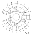
- Fig. 2 shows the embodiment in plan view.
- a hub 1 as a radially inner drive element can be connected to a shaft, not shown.
- the hub 1 comprises in a known manner, for example, an internal toothing 2, which merges into a shaft seat 3, which further merges into a perforated disc 4 with a bore 5, so that the hub 1, for example, with a stud, are screwed onto a nut can be connected to the shaft, not shown, for transmitting a torque.
- the hub 1 and the shaft are made in one piece, so the hub is a directly integrally formed on the shaft component of this.
- hub-side lobes 6 are formed, which are provided with a bore 7.
- the lugs 6 of the hub 1 are arranged extending radially outward relative to a substantially cylindrical base body 1a of the hub 1 at an angle of 90 °.
- a freewheel support 8 Radially outside the hub 1, a freewheel support 8 is arranged, are formed on the free-load carrier side lugs 9.
- the lugs 9 are bent radially outwardly at an angle of approximately 90 ° with respect to a base body 8a, which has a substantially cylindrical shape. In the lugs 9 holes 10 are respectively introduced.
- the lugs 6 and 9 are arranged approximately in the same radial plane to each other and are alternately connected to each other with leaf springs 11 as spring elements. So it is in each case a hub-side nose 6 connected to a free-load carrier nose 9.
- the leaf springs 11 each have two holes 12, so that a rivet bolt 13 is arranged through the bores 12 and in each case one bore 7 of the hub-side nose 6 or a bore 10 of the free-wheel carrier nose 9.
- the rivet bolts 13 are each capable of transmitting radially acting on these forces, thus forces in the circumferential direction of the hub 1 and the freewheel carrier 8.
- the stiffness of the leaf springs 11 in the circumferential direction is very large, the flexural rigidity in the axial direction of the axis of rotation 19th is comparatively low.
- a sliding bearing 14 is arranged, this may for example be a plastic bushing.
- the bush may be connected via a non-illustrated clamping connection or screw or the like with the freewheel carrier 8 or may be pressed into this.
- a freewheel 15 connects, wherein an inner shell 16 is connected in both the circumferential direction and in the axial direction non-positively with the freewheel carrier 8 and an outer shell 17 correspondingly in the axial and radial direction frictionally with a pulley 18 as a radially outer drive element connected is.
- the freewheel 15 has the task to transmit torque in a rotational direction between the hub 1 and pulley 18 to allow in the other direction of rotation as free as possible relative rotation between the two.
- the freewheel 15 may be formed in any manner as known in the art.
- the pulley 18 may alternatively be, for example, a gear or any other rotating component and is therefore generally referred to herein as a disc.
- the axial spring stiffness between hub 1 and freewheel carrier 8 and thus the axial spring stiffness between hub 1 and pulley 18 is dependent on the geometry of the leaf springs 11.
- the stiffness of the leaf springs 11 is thus determined as the stiffness of a beam.
- leaf springs 11 other spring elements could be used here.
- the lugs 6 and 9 could be made to coincide in the axial direction and be arranged between the two coil springs rubber buffer or the like.
- the hub 1 and the freewheel carrier 8 each have three lugs, but here the number of lugs can also be chosen differently, for example, two lugs, or four, five or more lugs.
Landscapes
- Engineering & Computer Science (AREA)
- General Engineering & Computer Science (AREA)
- Mechanical Engineering (AREA)
- Pulleys (AREA)
- Lens Barrels (AREA)
- Braking Arrangements (AREA)
Applications Claiming Priority (1)
| Application Number | Priority Date | Filing Date | Title |
|---|---|---|---|
| DE102005061620 | 2005-12-21 |
Publications (2)
| Publication Number | Publication Date |
|---|---|
| EP1801460A1 true EP1801460A1 (fr) | 2007-06-27 |
| EP1801460B1 EP1801460B1 (fr) | 2010-04-14 |
Family
ID=37891872
Family Applications (1)
| Application Number | Title | Priority Date | Filing Date |
|---|---|---|---|
| EP06024872A Not-in-force EP1801460B1 (fr) | 2005-12-21 | 2006-12-01 | Unité motrice ayant un composant moteur interne et un composant moteur externe |
Country Status (4)
| Country | Link |
|---|---|
| US (1) | US7784393B2 (fr) |
| EP (1) | EP1801460B1 (fr) |
| AT (1) | ATE464494T1 (fr) |
| DE (1) | DE502006006688D1 (fr) |
Cited By (1)
| Publication number | Priority date | Publication date | Assignee | Title |
|---|---|---|---|---|
| WO2009065717A3 (fr) * | 2007-11-21 | 2009-12-17 | Schaeffler Kg | Disque de roulement, poulie de tension et/ou de renvoi, et transmission à courroie trapézoïdale crantée |
Families Citing this family (4)
| Publication number | Priority date | Publication date | Assignee | Title |
|---|---|---|---|---|
| DE102010054134B3 (de) * | 2010-12-10 | 2012-04-12 | Thyssenkrupp Presta Ag | Kugelgewindetrieb |
| CN102562889B (zh) * | 2010-12-30 | 2016-05-25 | 洪涛 | 基于拨动式超越离合机构的通用驻车制动器及其操纵方法 |
| US9505920B2 (en) * | 2011-03-30 | 2016-11-29 | Fina Technology, Inc. | Polymer compositions for injection stretch blow molded articles |
| FR2995958B1 (fr) * | 2012-09-25 | 2016-02-19 | Skf Ab | Systeme mecanique a embrayage unidirectionnel et alternateur comprenant un tel systeme |
Citations (4)
| Publication number | Priority date | Publication date | Assignee | Title |
|---|---|---|---|---|
| DE19535889A1 (de) | 1995-09-27 | 1997-04-03 | Schaeffler Waelzlager Kg | Freilaufkupplung für einen Lichtmaschinenantrieb |
| DE19914529A1 (de) | 1998-04-02 | 1999-10-07 | Koyo Seiko Co | Riemenscheibeneinheit |
| EP1378677A2 (fr) * | 2002-07-01 | 2004-01-07 | Ntn Corporation | Poulie avec embrayage électromagnétique |
| EP1605189A2 (fr) * | 2004-06-07 | 2005-12-14 | Denso Automotive Deutschland GmbH | Dispositif de transmission de couple d'une poulie à un arbre |
Family Cites Families (11)
| Publication number | Priority date | Publication date | Assignee | Title |
|---|---|---|---|---|
| US2011822A (en) * | 1933-04-08 | 1935-08-20 | Niagara Machine & Tool Works | Cushioning means for clutches |
| US2957562A (en) * | 1958-04-25 | 1960-10-25 | Bendix Corp | Clutches |
| US5219053A (en) * | 1985-01-24 | 1993-06-15 | Hybo Science, Inc. | Unidirectional clutch with shell races |
| US5067601A (en) * | 1987-10-22 | 1991-11-26 | Castens Rudolf R | Clutches |
| US5035309A (en) * | 1989-05-08 | 1991-07-30 | Nobuo Takada | Rolling-contact bearing type clutch |
| JP2938966B2 (ja) * | 1990-11-21 | 1999-08-25 | テイエチケー株式会社 | ころがり軸受クラッチ |
| US5119915A (en) * | 1991-05-15 | 1992-06-09 | Dana Corporation | Electromagnetic coupling armature assembly with flux isolator springs |
| US5445256A (en) * | 1993-04-26 | 1995-08-29 | Nippondenso Co., Ltd. | Electromagnetic clutch |
| US5961424A (en) * | 1997-02-18 | 1999-10-05 | Schwinn Cycling & Fitness Inc. | Free wheel clutch mechanism for bicycle drive train |
| US6684992B2 (en) * | 2001-07-25 | 2004-02-03 | Ntn Corporation | Electronically controllable torque transmission device |
| DE10255913B4 (de) * | 2002-11-29 | 2005-07-28 | Timken Gmbh | Vorrichtung zum Dämpfen von Drehschwingungen |
-
2006
- 2006-12-01 DE DE502006006688T patent/DE502006006688D1/de active Active
- 2006-12-01 AT AT06024872T patent/ATE464494T1/de active
- 2006-12-01 EP EP06024872A patent/EP1801460B1/fr not_active Not-in-force
- 2006-12-14 US US11/638,914 patent/US7784393B2/en not_active Expired - Fee Related
Patent Citations (4)
| Publication number | Priority date | Publication date | Assignee | Title |
|---|---|---|---|---|
| DE19535889A1 (de) | 1995-09-27 | 1997-04-03 | Schaeffler Waelzlager Kg | Freilaufkupplung für einen Lichtmaschinenantrieb |
| DE19914529A1 (de) | 1998-04-02 | 1999-10-07 | Koyo Seiko Co | Riemenscheibeneinheit |
| EP1378677A2 (fr) * | 2002-07-01 | 2004-01-07 | Ntn Corporation | Poulie avec embrayage électromagnétique |
| EP1605189A2 (fr) * | 2004-06-07 | 2005-12-14 | Denso Automotive Deutschland GmbH | Dispositif de transmission de couple d'une poulie à un arbre |
Cited By (1)
| Publication number | Priority date | Publication date | Assignee | Title |
|---|---|---|---|---|
| WO2009065717A3 (fr) * | 2007-11-21 | 2009-12-17 | Schaeffler Kg | Disque de roulement, poulie de tension et/ou de renvoi, et transmission à courroie trapézoïdale crantée |
Also Published As
| Publication number | Publication date |
|---|---|
| EP1801460B1 (fr) | 2010-04-14 |
| US7784393B2 (en) | 2010-08-31 |
| DE502006006688D1 (de) | 2010-05-27 |
| ATE464494T1 (de) | 2010-04-15 |
| US20070137968A1 (en) | 2007-06-21 |
Similar Documents
| Publication | Publication Date | Title |
|---|---|---|
| DE102009042834A1 (de) | Antriebswellenanordnung für ein Getriebe eines Kraftfahrzeuges | |
| DE102007058018A1 (de) | Triebrad | |
| EP1939494A2 (fr) | Roue d'entraînement | |
| DE102007026195A1 (de) | Torsionsschwingungsdämpfer oder Dekoppler mit gewickelten Drahtfedern in einer Antriebsscheibe | |
| WO2008074399A1 (fr) | Amortisseur des vibrations torsionnelles présentant un élément primaire multicomposant | |
| EP1801460B1 (fr) | Unité motrice ayant un composant moteur interne et un composant moteur externe | |
| DE102008061589A1 (de) | Kupplungsscheibe | |
| WO2022033623A1 (fr) | Amortisseur à bascule pendulaire avec dispositif de friction réglable, et groupe motopropulseur hybride | |
| WO2009036727A1 (fr) | Amortisseur de vibrations torsionnelels | |
| WO2019161840A1 (fr) | Dispositif de découplage à poulie présentant un dispositif de pendule à force centrifuge pourvu d'un dispositif de frottement | |
| DE19737595A1 (de) | Schwungradanordnung mit einem Dämpfungsmechanismus, der eine eine Reibungshysterese erzeugende Vorrichtung aufweist | |
| DE102004044362B4 (de) | Kupplungsscheibenanordnung | |
| DE102012214996B4 (de) | Fliehkraftpendel mit Axialschwingungsdämpfung | |
| EP1503103B1 (fr) | Amortisseur de vibrations torsionelles | |
| DE102011082495B4 (de) | Schwungmassenvorrichtung | |
| DE102012209897B4 (de) | Nabeneinrichtung für einen Torsionsschwingungsdämpfer, Torsionsschwingungsdämpfer und Kraftfahrzeugkupplungsscheibe | |
| DE19634382C5 (de) | Zweimassen-Dämpfungsschwungrad, insbesondere für Kraftfahrzeuge, mit Momentbegrenzungsmitteln | |
| DE102011079603A1 (de) | Kupplungsscheibe für eine Reibungskupplung | |
| DE102010013632A1 (de) | Kupplungsscheibe | |
| DE102011103495A1 (de) | Kupplungswelle,Aktor,Nockenwellenverstellgetriebe und Nockenwellensteller | |
| DE19916871B4 (de) | Dämpfungsscheibenanordnung | |
| DE102017114444A1 (de) | Tilgereinrichtung | |
| DE102020113751A1 (de) | Übertragungsvorrichtung mit mindestens einem ersten Dämpfer und einem dynamischen Schwingungstilger | |
| DE102006056741A1 (de) | Antriebseinheit mit einem inneren Antriebselement und einem äußeren Antriebselement | |
| DE102018201534A1 (de) | Torsionsschwingungsdämpfer |
Legal Events
| Date | Code | Title | Description |
|---|---|---|---|
| PUAI | Public reference made under article 153(3) epc to a published international application that has entered the european phase |
Free format text: ORIGINAL CODE: 0009012 |
|
| AK | Designated contracting states |
Kind code of ref document: A1 Designated state(s): AT BE BG CH CY CZ DE DK EE ES FI FR GB GR HU IE IS IT LI LT LU LV MC NL PL PT RO SE SI SK TR |
|
| AX | Request for extension of the european patent |
Extension state: AL BA HR MK YU |
|
| 17P | Request for examination filed |
Effective date: 20071227 |
|
| 17Q | First examination report despatched |
Effective date: 20080201 |
|
| AKX | Designation fees paid |
Designated state(s): AT BE BG CH CY CZ DE DK EE ES FI FR GB GR HU IE IS IT LI LT LU LV MC NL PL PT RO SE SI SK TR |
|
| GRAP | Despatch of communication of intention to grant a patent |
Free format text: ORIGINAL CODE: EPIDOSNIGR1 |
|
| GRAS | Grant fee paid |
Free format text: ORIGINAL CODE: EPIDOSNIGR3 |
|
| GRAA | (expected) grant |
Free format text: ORIGINAL CODE: 0009210 |
|
| AK | Designated contracting states |
Kind code of ref document: B1 Designated state(s): AT BE BG CH CY CZ DE DK EE ES FI FR GB GR HU IE IS IT LI LT LU LV MC NL PL PT RO SE SI SK TR |
|
| REG | Reference to a national code |
Ref country code: GB Ref legal event code: FG4D Free format text: NOT ENGLISH |
|
| REG | Reference to a national code |
Ref country code: CH Ref legal event code: EP |
|
| REG | Reference to a national code |
Ref country code: IE Ref legal event code: FG4D Free format text: LANGUAGE OF EP DOCUMENT: GERMAN |
|
| REF | Corresponds to: |
Ref document number: 502006006688 Country of ref document: DE Date of ref document: 20100527 Kind code of ref document: P |
|
| REG | Reference to a national code |
Ref country code: NL Ref legal event code: VDEP Effective date: 20100414 |
|
| LTIE | Lt: invalidation of european patent or patent extension |
Effective date: 20100414 |
|
| RAP2 | Party data changed (patent owner data changed or rights of a patent transferred) |
Owner name: SCHAEFFLER TECHNOLOGIES GMBH & CO. KG |
|
| PG25 | Lapsed in a contracting state [announced via postgrant information from national office to epo] |
Ref country code: ES Free format text: LAPSE BECAUSE OF FAILURE TO SUBMIT A TRANSLATION OF THE DESCRIPTION OR TO PAY THE FEE WITHIN THE PRESCRIBED TIME-LIMIT Effective date: 20100725 Ref country code: NL Free format text: LAPSE BECAUSE OF FAILURE TO SUBMIT A TRANSLATION OF THE DESCRIPTION OR TO PAY THE FEE WITHIN THE PRESCRIBED TIME-LIMIT Effective date: 20100414 Ref country code: LT Free format text: LAPSE BECAUSE OF FAILURE TO SUBMIT A TRANSLATION OF THE DESCRIPTION OR TO PAY THE FEE WITHIN THE PRESCRIBED TIME-LIMIT Effective date: 20100414 Ref country code: SE Free format text: LAPSE BECAUSE OF FAILURE TO SUBMIT A TRANSLATION OF THE DESCRIPTION OR TO PAY THE FEE WITHIN THE PRESCRIBED TIME-LIMIT Effective date: 20100414 |
|
| REG | Reference to a national code |
Ref country code: IE Ref legal event code: FD4D |
|
| PG25 | Lapsed in a contracting state [announced via postgrant information from national office to epo] |
Ref country code: SI Free format text: LAPSE BECAUSE OF FAILURE TO SUBMIT A TRANSLATION OF THE DESCRIPTION OR TO PAY THE FEE WITHIN THE PRESCRIBED TIME-LIMIT Effective date: 20100414 Ref country code: IS Free format text: LAPSE BECAUSE OF FAILURE TO SUBMIT A TRANSLATION OF THE DESCRIPTION OR TO PAY THE FEE WITHIN THE PRESCRIBED TIME-LIMIT Effective date: 20100814 Ref country code: FI Free format text: LAPSE BECAUSE OF FAILURE TO SUBMIT A TRANSLATION OF THE DESCRIPTION OR TO PAY THE FEE WITHIN THE PRESCRIBED TIME-LIMIT Effective date: 20100414 Ref country code: LV Free format text: LAPSE BECAUSE OF FAILURE TO SUBMIT A TRANSLATION OF THE DESCRIPTION OR TO PAY THE FEE WITHIN THE PRESCRIBED TIME-LIMIT Effective date: 20100414 |
|
| PG25 | Lapsed in a contracting state [announced via postgrant information from national office to epo] |
Ref country code: CY Free format text: LAPSE BECAUSE OF FAILURE TO SUBMIT A TRANSLATION OF THE DESCRIPTION OR TO PAY THE FEE WITHIN THE PRESCRIBED TIME-LIMIT Effective date: 20100512 Ref country code: PL Free format text: LAPSE BECAUSE OF FAILURE TO SUBMIT A TRANSLATION OF THE DESCRIPTION OR TO PAY THE FEE WITHIN THE PRESCRIBED TIME-LIMIT Effective date: 20100414 Ref country code: GR Free format text: LAPSE BECAUSE OF FAILURE TO SUBMIT A TRANSLATION OF THE DESCRIPTION OR TO PAY THE FEE WITHIN THE PRESCRIBED TIME-LIMIT Effective date: 20100715 |
|
| PG25 | Lapsed in a contracting state [announced via postgrant information from national office to epo] |
Ref country code: EE Free format text: LAPSE BECAUSE OF FAILURE TO SUBMIT A TRANSLATION OF THE DESCRIPTION OR TO PAY THE FEE WITHIN THE PRESCRIBED TIME-LIMIT Effective date: 20100414 Ref country code: IE Free format text: LAPSE BECAUSE OF FAILURE TO SUBMIT A TRANSLATION OF THE DESCRIPTION OR TO PAY THE FEE WITHIN THE PRESCRIBED TIME-LIMIT Effective date: 20100414 Ref country code: DK Free format text: LAPSE BECAUSE OF FAILURE TO SUBMIT A TRANSLATION OF THE DESCRIPTION OR TO PAY THE FEE WITHIN THE PRESCRIBED TIME-LIMIT Effective date: 20100414 Ref country code: PT Free format text: LAPSE BECAUSE OF FAILURE TO SUBMIT A TRANSLATION OF THE DESCRIPTION OR TO PAY THE FEE WITHIN THE PRESCRIBED TIME-LIMIT Effective date: 20100816 |
|
| PLBE | No opposition filed within time limit |
Free format text: ORIGINAL CODE: 0009261 |
|
| STAA | Information on the status of an ep patent application or granted ep patent |
Free format text: STATUS: NO OPPOSITION FILED WITHIN TIME LIMIT |
|
| PG25 | Lapsed in a contracting state [announced via postgrant information from national office to epo] |
Ref country code: RO Free format text: LAPSE BECAUSE OF FAILURE TO SUBMIT A TRANSLATION OF THE DESCRIPTION OR TO PAY THE FEE WITHIN THE PRESCRIBED TIME-LIMIT Effective date: 20100414 Ref country code: CZ Free format text: LAPSE BECAUSE OF FAILURE TO SUBMIT A TRANSLATION OF THE DESCRIPTION OR TO PAY THE FEE WITHIN THE PRESCRIBED TIME-LIMIT Effective date: 20100414 Ref country code: SK Free format text: LAPSE BECAUSE OF FAILURE TO SUBMIT A TRANSLATION OF THE DESCRIPTION OR TO PAY THE FEE WITHIN THE PRESCRIBED TIME-LIMIT Effective date: 20100414 |
|
| 26N | No opposition filed |
Effective date: 20110117 |
|
| PG25 | Lapsed in a contracting state [announced via postgrant information from national office to epo] |
Ref country code: IT Free format text: LAPSE BECAUSE OF FAILURE TO SUBMIT A TRANSLATION OF THE DESCRIPTION OR TO PAY THE FEE WITHIN THE PRESCRIBED TIME-LIMIT Effective date: 20100414 |
|
| BERE | Be: lapsed |
Owner name: LUK LAMELLEN UND KUPPLUNGSBAU BETEILIGUNGS K.G. Effective date: 20101231 |
|
| PG25 | Lapsed in a contracting state [announced via postgrant information from national office to epo] |
Ref country code: MC Free format text: LAPSE BECAUSE OF NON-PAYMENT OF DUE FEES Effective date: 20101231 |
|
| REG | Reference to a national code |
Ref country code: CH Ref legal event code: PL |
|
| GBPC | Gb: european patent ceased through non-payment of renewal fee |
Effective date: 20101201 |
|
| PG25 | Lapsed in a contracting state [announced via postgrant information from national office to epo] |
Ref country code: BE Free format text: LAPSE BECAUSE OF NON-PAYMENT OF DUE FEES Effective date: 20101231 |
|
| PG25 | Lapsed in a contracting state [announced via postgrant information from national office to epo] |
Ref country code: LI Free format text: LAPSE BECAUSE OF NON-PAYMENT OF DUE FEES Effective date: 20101231 Ref country code: CH Free format text: LAPSE BECAUSE OF NON-PAYMENT OF DUE FEES Effective date: 20101231 |
|
| PG25 | Lapsed in a contracting state [announced via postgrant information from national office to epo] |
Ref country code: GB Free format text: LAPSE BECAUSE OF NON-PAYMENT OF DUE FEES Effective date: 20101201 |
|
| PG25 | Lapsed in a contracting state [announced via postgrant information from national office to epo] |
Ref country code: BG Free format text: LAPSE BECAUSE OF FAILURE TO SUBMIT A TRANSLATION OF THE DESCRIPTION OR TO PAY THE FEE WITHIN THE PRESCRIBED TIME-LIMIT Effective date: 20100414 Ref country code: LU Free format text: LAPSE BECAUSE OF NON-PAYMENT OF DUE FEES Effective date: 20101201 Ref country code: HU Free format text: LAPSE BECAUSE OF FAILURE TO SUBMIT A TRANSLATION OF THE DESCRIPTION OR TO PAY THE FEE WITHIN THE PRESCRIBED TIME-LIMIT Effective date: 20101015 |
|
| REG | Reference to a national code |
Ref country code: DE Ref legal event code: R081 Ref document number: 502006006688 Country of ref document: DE Owner name: SCHAEFFLER TECHNOLOGIES AG & CO. KG, DE Free format text: FORMER OWNER: SCHAEFFLER TECHNOLOGIES GMBH & CO. KG, 91074 HERZOGENAURACH, DE Effective date: 20120828 Ref country code: DE Ref legal event code: R081 Ref document number: 502006006688 Country of ref document: DE Owner name: SCHAEFFLER TECHNOLOGIES GMBH & CO. KG, DE Free format text: FORMER OWNER: SCHAEFFLER TECHNOLOGIES GMBH & CO. KG, 91074 HERZOGENAURACH, DE Effective date: 20120828 |
|
| PG25 | Lapsed in a contracting state [announced via postgrant information from national office to epo] |
Ref country code: TR Free format text: LAPSE BECAUSE OF FAILURE TO SUBMIT A TRANSLATION OF THE DESCRIPTION OR TO PAY THE FEE WITHIN THE PRESCRIBED TIME-LIMIT Effective date: 20100414 |
|
| REG | Reference to a national code |
Ref country code: AT Ref legal event code: MM01 Ref document number: 464494 Country of ref document: AT Kind code of ref document: T Effective date: 20111201 |
|
| PG25 | Lapsed in a contracting state [announced via postgrant information from national office to epo] |
Ref country code: AT Free format text: LAPSE BECAUSE OF NON-PAYMENT OF DUE FEES Effective date: 20111201 |
|
| PG25 | Lapsed in a contracting state [announced via postgrant information from national office to epo] |
Ref country code: BG Free format text: LAPSE BECAUSE OF FAILURE TO SUBMIT A TRANSLATION OF THE DESCRIPTION OR TO PAY THE FEE WITHIN THE PRESCRIBED TIME-LIMIT Effective date: 20100714 |
|
| REG | Reference to a national code |
Ref country code: DE Ref legal event code: R081 Ref document number: 502006006688 Country of ref document: DE Owner name: SCHAEFFLER TECHNOLOGIES GMBH & CO. KG, DE Free format text: FORMER OWNER: SCHAEFFLER TECHNOLOGIES AG & CO. KG, 91074 HERZOGENAURACH, DE Effective date: 20140218 Ref country code: DE Ref legal event code: R081 Ref document number: 502006006688 Country of ref document: DE Owner name: SCHAEFFLER TECHNOLOGIES AG & CO. KG, DE Free format text: FORMER OWNER: SCHAEFFLER TECHNOLOGIES AG & CO. KG, 91074 HERZOGENAURACH, DE Effective date: 20140218 |
|
| REG | Reference to a national code |
Ref country code: DE Ref legal event code: R081 Ref document number: 502006006688 Country of ref document: DE Owner name: SCHAEFFLER TECHNOLOGIES AG & CO. KG, DE Free format text: FORMER OWNER: SCHAEFFLER TECHNOLOGIES GMBH & CO. KG, 91074 HERZOGENAURACH, DE Effective date: 20150213 |
|
| REG | Reference to a national code |
Ref country code: FR Ref legal event code: PLFP Year of fee payment: 10 |
|
| REG | Reference to a national code |
Ref country code: FR Ref legal event code: PLFP Year of fee payment: 11 |
|
| REG | Reference to a national code |
Ref country code: FR Ref legal event code: PLFP Year of fee payment: 12 |
|
| PGFP | Annual fee paid to national office [announced via postgrant information from national office to epo] |
Ref country code: FR Payment date: 20171226 Year of fee payment: 12 |
|
| PGFP | Annual fee paid to national office [announced via postgrant information from national office to epo] |
Ref country code: DE Payment date: 20180228 Year of fee payment: 12 |
|
| REG | Reference to a national code |
Ref country code: DE Ref legal event code: R119 Ref document number: 502006006688 Country of ref document: DE |
|
| PG25 | Lapsed in a contracting state [announced via postgrant information from national office to epo] |
Ref country code: DE Free format text: LAPSE BECAUSE OF NON-PAYMENT OF DUE FEES Effective date: 20190702 Ref country code: FR Free format text: LAPSE BECAUSE OF NON-PAYMENT OF DUE FEES Effective date: 20181231 |
|
| P01 | Opt-out of the competence of the unified patent court (upc) registered |
Effective date: 20230522 |