EP1799892B1 - High-performance device for air interlacing of a yarn and corresponding method - Google Patents
High-performance device for air interlacing of a yarn and corresponding method Download PDFInfo
- Publication number
- EP1799892B1 EP1799892B1 EP05802392A EP05802392A EP1799892B1 EP 1799892 B1 EP1799892 B1 EP 1799892B1 EP 05802392 A EP05802392 A EP 05802392A EP 05802392 A EP05802392 A EP 05802392A EP 1799892 B1 EP1799892 B1 EP 1799892B1
- Authority
- EP
- European Patent Office
- Prior art keywords
- yarn
- interlacing
- chamber
- wall
- jet
- Prior art date
- Legal status (The legal status is an assumption and is not a legal conclusion. Google has not performed a legal analysis and makes no representation as to the accuracy of the status listed.)
- Not-in-force
Links
Images


Classifications
-
- D—TEXTILES; PAPER
- D02—YARNS; MECHANICAL FINISHING OF YARNS OR ROPES; WARPING OR BEAMING
- D02J—FINISHING OR DRESSING OF FILAMENTS, YARNS, THREADS, CORDS, ROPES OR THE LIKE
- D02J1/00—Modifying the structure or properties resulting from a particular structure; Modifying, retaining, or restoring the physical form or cross-sectional shape, e.g. by use of dies or squeeze rollers
- D02J1/08—Interlacing constituent filaments without breakage thereof, e.g. by use of turbulent air streams
Definitions
- This invention relates in general to a device for the interlacing of a yarn, and more precisely to an air type interlacing device, i.e. one suitable for producing the effect of interlacing of a yarn, as it traverses the device, by intersecting this yarn with a continuous jet of compressed air.
- the invention also relates to a corresponding method for air interlacing of a yarn.
- the interlacing operation may be considered to be a fundamental part of a more general process, often called texturizing, the purpose of which is to have a starting textile element, essentially consisting of a synthetic thread made up of numerous filaments, acquire properties, outer appearance, and suitability for subsequent machining work that are typical of a conventional yarn or warp thread.
- the starting multifilament synthetic thread is appropriately treated and transformed in such a way as to assume characteristics of stability, resistance, volume and softness that are comparable with those of a traditional yarn, made for instance from natural fibres, thus making it possible, inter alia, to machine the yarn during the successive steps envisaged in the textile cycle, among which - by way of example only - weaving.
- the interlacing operation consists specifically in treating the starting composite synthetic yarn which, as it is composed of a plurality of filaments arranged according to a fairly simple, orderly structure, is substantially instable and lacking in cohesion, in such a way as to cause a telescoping and a mixing of this filamentary structure, with the resulting creation of bonds between the filaments and the end result of conferring stability, compactness and resistance to the interlaced yarn thus produced which, thanks to these characteristics becomes suitable for the subsequent textile machining work.
- an interlaced yarn produced with the current techniques has typically, along its length or longitudinal extension, a complex filamentary structure, characterized by an alternation of zones having a finer section with zones of a thicker section, in which the zones of finer section, also called knots or zones of cohesion, correspond to portions of the yarn in which there is a concentration of the bonds between the filaments produced by the interlacing operation, and in which the zones of thicker section correspond to portions of yarn where there are either none of these bonds or where they are sparse, and where therefore there is less binding among the filaments.
- the number of these knots, per unit of length of the interlaced yarn produced, is often considered as a highly significant parameter, offering a quantitative definition of the quality and yield of the interlacing operation.
- the jet of compressed air creates around the yarn, while it continuously advances along this guide channel, a turbulent flow that interacts with the yarn and causes an entangling of its filaments, thus creating a multitude of bonds between these, with the result of conferring robustness and stability on the interlaced yarn thus obtained as it is released at the outlet of the guide channel.
- the jet of compressed air is emitted constantly by a nozzle which opens upon the closed space around the yarn as it advances along the guide channel, so as to create and feed continuously the turbulent flow needed to produce the interlacing between the filaments of the yarn.
- the air then departs along the guide channel from the enclosed space arranged about the yarn where the turbulent flow is created, before being dispersed into the external environment.
- the compressed air needed for constantly feeding the corresponding jet is produced continuously by a suitable compression station.
- the industrial machinery and systems for the production of texturized and/or interlaced yarns comprise a very large number of interlacing units, so as to simultaneously produce in an efficient and economically sustainable way a large number of interlaced yarns, in the massive quantities required by the market.
- the compression stations must be constructed of appropriate dimensions corresponding to this large number of interlacing units, in order to be able to produce under steady conditions a considerable quantity of compressed air, such as the various interlacing units globally require.
- one device for air interlacing of a yarn is known from the US patent no. 6,438,812 B1 which has an interlacing duct, suitable for longitudinally receiving a synthetic yarn to be interlaced, in turn comprising a first entrance segment, a second central segment, and a third exit segment, in which the second central segment, placed between the first and the third segments, has a transverse section that is greater than that of the first and third segments, and in which the internal volume of the second segment is closed off by a first concave wall bearing a nozzle for emission of a jet of compressed air and by a second flat wall, opposite the first concave wall and suitable for receiving and deflecting the jet of compressed air emitted by the nozzle and intersecting the yarn to be interlaced.
- a device for air interlacing of a yarn is provided with an interlacing duct, suitable for receiving the yarn to be interlaced, of constant section, which can be triangular, or circular, or oval, etc. in the longitudinal direction along the path followed by the yarn through the device, with a nozzle for emission of the jet of compressed air placed in correspondence with a central zone of the constant section channel.
- the document EP 0 564 400 A1 in turn describes an interlacing device that has a variable section interlacing duct defined by convex and diverging surfaces towards the yarn entrance and exit zones, with the nozzle for emission of the jet of compressed air arranged local to the lesser section of the channel.
- the Applicant realized how in general the configuration of the interlacing duct, and more specifically the shape, dimensions and arrangement of the walls that delimit, along this duct, the chamber that receives the jet of compressed air and inside which the turbulent flow and the whirls responsible for interlacing of the yarn are generated, constitute fundamental points and parameters, to which much attention must therefore be dedicated, when wishing to optimize the characteristics of the turbulent flow, limit the consumption of compressed air, and generally, enhance the performance of the interlacing device.
- the invention in a first aspect, corresponding to the main independent claim, relates to a device for air interlacing of a yarn which comprises an interlacing duct along which the yarn passes and is guided through the device, in which the interlacing duct has an interlacing chamber which is delimited by a first emitting wall bearing a nozzle for the emission of a jet of compressed air inside the interlacing chamber, and by a second deflecting wall, opposite the first wall, suitable for receiving and deflecting the jet of compressed air emitted by the nozzle and intersecting the yarn to be interlaced, and in which the device is characterized in that the second wall has a concave shape.
- the invention in a second aspect complementary to the first, relates to a method for air interlacing of a yarn comprising the following steps:
- first concave surface is associated with a second surface arranged, with respect to the yarn, on the side of emission of the jet of compressed air and is suitable for receiving the air deflected by the first concave surface so as to define with the latter-named an interlacing chamber around the yarn as it advances.
- the concave wall of the interlacing chamber that receives and deflects the jet of compressed air is specifically defined by a semi-spherical surface.
- a resonance chamber is associated with the interlacing chamber and opens on the relative concave wall in order to increase the efficacy of the air whirls inside the interlacing chamber.
- a device for air interlacing of a yarn Y is generically designated with the numeral 10, and is for example integrated in a more complex texturizing unit, of known type and therefore only referred to here only summarily and not represented in the drawings.
- the interlacing device 10 is represented in broken-down or exploded form and defines a longitudinal axis 11, along which the yarn Y, as it advances at a given feed speed V in the direction indicated by an arrow 18, accedes to and completely traverses the device 10, where it is interlaced.
- the yarn Y which is produced in a known way by a production unit operating before the device 10, is of synthetic type and is formed by numerous filaments.
- the portion of yarn Y which has already undergone the interlacing operation and which is released from the device 10 towards other stations of the texturizing unit, is indicated with Y", and has instead its filaments in a complex and interlaced structure.
- portion Y coming out of the device 10, is characterized along its length by a succession of fine zones, or knots, indicated with Y1, in which the bonds between the filaments made by the device 10 are concentrated, and thick zones, indicated with Y2, in which these bonds have not formed, and are therefore practically missing, or have been formed to a lesser extent.
- the knots Y1 are reciprocally spaced out along the yarn Y according to a pitch which, as a result of the interlacing operation produced by the device 10, is substantially constant.
- the structure of the interlacing device 10 is, according to a known concept, of an opening type, and is formed essentially by two bodies or blocks or main parts, respectively a first body 12 and a second body 13, suitable for being opened and closed with respect to one another, in particular to permit introduction of the yarn Y through the device 10, and also access to the inside of the device 10, for instance for maintenance and cleaning purposes.
- the two bodies 12 and 13 can be exactly mounted and fastened one on top of the other in correspondence with and along a common, flat contact surface 15, thanks to known type fastening and reference means.
- FIG. 1 For clarity's sake, these known fastening means are depicted in Fig. 1 with two plugs 14, represented by the dot and dash line and suitable for cooperating with corresponding holes 14a formed on the bodies 12 and 13.
- the first entrance channel 22 and the second exit channel 23 are provided respectively for receiving, at the entrance to the device 10, the portion Y', to be interlaced, of the yarn Y, and for releasing, at the exit of the device 10, the portion Y" of the yarn Y, after it has been interlaced.
- first entrance channel 22 and the second exit channel 23 preferably have a respective transverse section, on the plane normal to the axis 11 i.e. to the feeding direction of the yarn Y along the duct 21, which is less than the transverse section of the intermediate interlacing chamber 24, again on this plane.
- the interlacing chamber 24 is defined and delimited, along the interlacing duct 21, by two opposite walls, respectively 24a and 24b, also called emitting wall and deflecting wall, the former of which made in the first body 12 and the second in the second body 13.
- a nozzle 26, for the emission of a continuous jet of compressed air inside the volume defined by the interlacing chamber 24, is made in the first body 12 and opens onto the interlacing chamber 24, along the relative wall 24a.
- the compressed air that feeds the nozzle 26 at a nominal pressure Pn to generate the corresponding jet of compressed air is produced and supplied continuously, as indicated by an arrow 27, by means of a known type of compressed air plant, not depicted in any of the drawings, which is adapted to be suitably controlled in order to maintain the compressed air that feeds the nozzle 26 at the nominal pressure Pn in time.
- air is to be understood as also indicating other fluids, liquid or gaseous, capable in any event of creating phenomena of turbulence around the yarn, that are suitable for interlacing it.
- the nozzle 26 is defined by a cylindrical hole, of diameter ⁇ 1, substantially oriented along a respective axis 26a in a direction perpendicular to the axis 11 of the device 10, and is also disposed in a central and symmetrical position with respect to the internal volume of the interlacing chamber 24.
- the wall 24b which delimits the interlacing chamber 24 and is arranged in front of the nozzle 26 for receiving and deflecting the corresponding jet of compressed air in order to create the turbulence effect inside the same chamber 24, as better explained in the following, has a special concave shape which is defined by a concave surface on both the transverse and longitudinal planes with respect to the axis 11, i.e. to yarn Y feeding path through the device 10.
- the wall 24a of the turbulence chamber 24, opposite the concave wall 24b and bearing the nozzle 26, in turn has a flat shape defined by a flat surface that corresponds to the contact plane 15 between the two bodies 12 and 13, and is suitable for enclosing the concave surface of the wall 24b.
- the interlacing chamber 24 is completely embedded in the second body 13.
- the entrance and exit channels, respectively 22 and 23, are in turn carved out completely in the second body 13, in such a way as to join, at opposite ends, with the concave surface of the wall 24b, thus leaving unaltered the flat surface of the first body 12, along the plane of contact 15.
- the body 12 extends, in the direction of the axis 11 and externally with respect to the entrance and exit channels 22 and 23, along the same plane of contact 15 as defines the flat wall 24a of the interlacing chamber 24, in such a way as to define a flat guide wall 12a, for guiding and supporting the yarn Y, as it traverses the device 10, as will be described better below.
- the concave shape of the wall 24b is produced according to a semi-spherical surface, defined by a radius R, wherein this semi-spherical surface is enclosed along the perimeter by the flat surface of the wall 24a, so as to form the interlacing chamber 24, and in which the nozzle 26 opens on the said interlacing chamber 24 in correspondence with the centre of the sphere of radius R defining this semi-spherical surface
- the entrance and exit channels 22 and 23, made in the body 13, have in turn, a constant transverse section along the axis 11, in particular rectangular shape, defined by a width A and a height B, measured respectively along and starting from the contact plane 15 between the two bodies 12 and 13.
- the interlacing device 10 also includes a compartment 32, also called resonance chamber, which is associated with the interlacing chamber 24 and which opens upon the bottom of the concave wall 24b, in correspondence with the zone of maximum depth of said concave wall 24b, i.e. of maximum distance from the flat wall 24a.
- a compartment 32 also called resonance chamber, which is associated with the interlacing chamber 24 and which opens upon the bottom of the concave wall 24b, in correspondence with the zone of maximum depth of said concave wall 24b, i.e. of maximum distance from the flat wall 24a.
- the resonance chamber 32 extends, through the body 13 and in a directly substantially in line with the axis 26a of the nozzle 26, between an opening 32a made in the concave wall 24b in an area in front of the nozzle 26 and which accordingly puts the volume of the resonance chamber 32 in communication with the volume of the interlacing chamber 24, and an opposite closed bottom 32b of the resonance chamber 32, which is made for instance by a closing body 16 attached to the body 13.
- the area or section of the opening 32° of the resonance chamber 32 along the wall 24b, is significantly lower than the area or section of the interlacing chamber 24, seen frontally from the side of the nozzle 26, namely in a normal direction to the plane 15, as is clearly shown in Fig. 4 .
- this resonance chamber 32 is to accentuate the turbulence and efficacy of the air flow and relative whirls which are set up about the yarn Y, in order to produce the interlacing effect, as better described in the following.
- the resonance chamber 32 is formed, according to a cylindrical shape defined by a diameter ⁇ 2 and for a depth P, in the normal direction to the plane of contact 15 and along an axis passing through the centre of the sphere of radius R defining the wall 24b, as is clearly visible from the drawings.
- the table following sets out the preferred ranges, defined by a minimum value Min and a maximum value Max, and the preferred nominal values Nom, for the dimensions of the fundamental parts constituting the interlacing device 10 and define the shape it will have.
- the yarn Y is fed according to known arrangements at a constant speed V to the interlacing device 10, along the relative axis 11, so that the yarn Y continuously traverses the device 10, being guided in its traversing movement by the entrance and exit channels 22 and 23, and also by the wall 12a of the first body 12.
- the nozzle 26 is fed with compressed air, at the nominal pressure Pn, by the corresponding plant, so as to continuously emit a continuous jet of air 31 towards the concave wall 24b, in a direction substantially perpendicular to the path of the yarn Y through the device 10.
- the jet of air 31 intersects the yarn Y, as the latter advances at speed V through the interlacing chamber 24, and is also subjected, in the area of the wall 24b, to a deflection, guided and controlled by the special concave shape of the wall 24b, which acts to direct the main air flow coming from the nozzle 26 backwards, again towards the yarn Y, as indicated by the lines of flow 31a.
- the jet of compressed air 31 activates, inside the interlacing chamber 24 and around the advancing yarn Y, a highly turbulent flow of air, the whirls of which interact with the yarn Y and are such as to determine the entanglement of its filaments, with the resultant transformation of the structure of the yarn Y from a simple filamentary structure to a more complex and interlaced structure, characterized by knots Y2 in correspondence with which the bonds between the filaments of the yarn Y are concentrated.
- the resonance chamber 32 receives at least a part of the jet of compressed air emitted by the nozzle 31, and in this way cooperates with the interlacing chamber 24, establishing a continuous and rapid exchange of air with the latter-named, so as to accentuate the turbulence of the continuous flow of air which is activated around the yarn Y, in order to produce the effect of entanglement and interlacing between its filaments.
- the resonance chamber 32 operates, in association with the interlacing chamber 24, as a kind of fluodynamic resonator, which establishes resonance conditions that amplify the intensity and efficacy of the air whirls inside the chamber 24.
- the interlacing device 10 thanks to the special configuration of the interlacing chamber 24, characterized by the concave wall 24b suitable for receiving and deflecting the jet of compressed air 31 emitted by the nozzle 26, and thanks also to the presence of the resonance chamber 32 associated with the interlacing chamber 24, is capable of obtaining a conspicuous saving in the consumption of compressed air, for a like quality of interlaced yarn produced and in particular for a like number of knots per unit of length of yarn interlaced.
- the interlacing device of the invention appears capable of producing an interlaced yarn that fully satisfies all the necessary structural and quality requirements, and also of supporting a production capacity equal to that required by the industry, but at a significantly lower cost in terms of consumption of compressed air than the air interlacing devices currently in use.
- the concavity of the wall 24b that receives the jet of compressed air 31 may be defined by any surface other than a semi-spherical surface, for instance by an elliptical surface or similar.
- the entrance channel 122 and the exit channel 123 arranged to the sides of the interlacing chamber 124 and made in the second body 113, have a trapezoidal or similar transverse section, rather than rectangular, in the plane normal to the yarn feeding path Y through the device 110.
- the entrance and exit channels of the yarn may be made, over their entire longitudinal extension, partly in the first body and partly in the second body of the interlacing device.
- the interlacing chamber 424 exhibits frontally, from the side of the first body 412, an elongated shape along an axis of symmetry, selected from either the axis 411 corresponding to the yarn feeding path Y, or the axis 408 normal to the path, and consequently, on account of this elongated shape, the interlacing chamber 424 has a first concavity, on the longitudinal plane containing the path of the yarn, and a second concavity, on the plane transversal to the yarn path, in which these two concavities are geometrically different from one another, and for instance at least one of these is defined in section by a semi-elliptical or similar profile 407, as depicted in Fig. 5f .
Abstract
Description
- This invention relates in general to a device for the interlacing of a yarn, and more precisely to an air type interlacing device, i.e. one suitable for producing the effect of interlacing of a yarn, as it traverses the device, by intersecting this yarn with a continuous jet of compressed air. The invention also relates to a corresponding method for air interlacing of a yarn.
- As is known, in textile technology, the interlacing operation may be considered to be a fundamental part of a more general process, often called texturizing, the purpose of which is to have a starting textile element, essentially consisting of a synthetic thread made up of numerous filaments, acquire properties, outer appearance, and suitability for subsequent machining work that are typical of a conventional yarn or warp thread.
- Accordingly, in the texturizing process, the starting multifilament synthetic thread is appropriately treated and transformed in such a way as to assume characteristics of stability, resistance, volume and softness that are comparable with those of a traditional yarn, made for instance from natural fibres, thus making it possible, inter alia, to machine the yarn during the successive steps envisaged in the textile cycle, among which - by way of example only - weaving.
- In this context, the interlacing operation consists specifically in treating the starting composite synthetic yarn which, as it is composed of a plurality of filaments arranged according to a fairly simple, orderly structure, is substantially instable and lacking in cohesion, in such a way as to cause a telescoping and a mixing of this filamentary structure, with the resulting creation of bonds between the filaments and the end result of conferring stability, compactness and resistance to the interlaced yarn thus produced which, thanks to these characteristics becomes suitable for the subsequent textile machining work.
- In particular, an interlaced yarn produced with the current techniques has typically, along its length or longitudinal extension, a complex filamentary structure, characterized by an alternation of zones having a finer section with zones of a thicker section, in which the zones of finer section, also called knots or zones of cohesion, correspond to portions of the yarn in which there is a concentration of the bonds between the filaments produced by the interlacing operation, and in which the zones of thicker section correspond to portions of yarn where there are either none of these bonds or where they are sparse, and where therefore there is less binding among the filaments.
- The number of these knots, per unit of length of the interlaced yarn produced, is often considered as a highly significant parameter, offering a quantitative definition of the quality and yield of the interlacing operation.
- An important interlacing technique, used widely throughout the industry, makes use of a jet of compressed air, emitted inside a substantially enclosed space or volume, delimited by walls, which is associated with a channel-shaped guide, in turn provided for receiving in the longitudinal direction a composite yarn to be interlaced, made up of various filaments.
- In this technique, the jet of compressed air creates around the yarn, while it continuously advances along this guide channel, a turbulent flow that interacts with the yarn and causes an entangling of its filaments, thus creating a multitude of bonds between these, with the result of conferring robustness and stability on the interlaced yarn thus obtained as it is released at the outlet of the guide channel.
- The jet of compressed air is emitted constantly by a nozzle which opens upon the closed space around the yarn as it advances along the guide channel, so as to create and feed continuously the turbulent flow needed to produce the interlacing between the filaments of the yarn.
- The air then departs along the guide channel from the enclosed space arranged about the yarn where the turbulent flow is created, before being dispersed into the external environment.
- The compressed air needed for constantly feeding the corresponding jet is produced continuously by a suitable compression station.
- In practice, the industrial machinery and systems for the production of texturized and/or interlaced yarns comprise a very large number of interlacing units, so as to simultaneously produce in an efficient and economically sustainable way a large number of interlaced yarns, in the massive quantities required by the market.
- Therefore, in relation to these machines and systems, the compression stations must be constructed of appropriate dimensions corresponding to this large number of interlacing units, in order to be able to produce under steady conditions a considerable quantity of compressed air, such as the various interlacing units globally require.
- Correspondingly the consumption under steady conditions of electric power by these compression stations to produce the compressed air needed by the interlacing units, is, on the whole, also high and very significant from the viewpoint of interlaced yarn manufacturing costs.
- From what has been said, it will be obvious how it is essential and important, if we are to reduce both the costs of installing and operating the compression stations, and also the incidence of the power quota on production of the interlaced yarns, to try to obtain an interlaced yarn with the minimum consumption of compressed air, or better, to attempt to have a consumption of compressed air that is as low as possible, for a given quantity of interlaced yarn produced and for a like interlacing quality.
- For it is clear that the immediate effect of a reduction in the consumption of compressed air, in whatever way it is obtained, is an improvement in the general performance of the interlacing operation, with undoubted advantages both in technical terms and economic terms.
- The state of the art features numerous solutions and improvements concerning devices for air interlacing of yarns; similarly the market offers a broad range of models and types of these interlacing devices, produced by some of the leading manufacturers.
- For example, one device for air interlacing of a yarn is known from the
US patent no. 6,438,812 B1 which has an interlacing duct, suitable for longitudinally receiving a synthetic yarn to be interlaced, in turn comprising a first entrance segment, a second central segment, and a third exit segment, in which the second central segment, placed between the first and the third segments, has a transverse section that is greater than that of the first and third segments, and in which the internal volume of the second segment is closed off by a first concave wall bearing a nozzle for emission of a jet of compressed air and by a second flat wall, opposite the first concave wall and suitable for receiving and deflecting the jet of compressed air emitted by the nozzle and intersecting the yarn to be interlaced. - A similar configuration for a central turbulence chamber and associated yarn entrance and exit channels in a yarn air interlacing device is described by the
US patent no. 4,644,620 . - Again numerous other types and solutions for yarn air interlacing devices have been put forward by the known art. For instance, in each of the solutions proposed by the documents
US 5,841,787 ,US 5,081,631 ,US 4,011,640 andEP 1 207 226 A1 , a device for air interlacing of a yarn is provided with an interlacing duct, suitable for receiving the yarn to be interlaced, of constant section, which can be triangular, or circular, or oval, etc. in the longitudinal direction along the path followed by the yarn through the device, with a nozzle for emission of the jet of compressed air placed in correspondence with a central zone of the constant section channel. - The document
EP 0 564 400 A1 in turn describes an interlacing device that has a variable section interlacing duct defined by convex and diverging surfaces towards the yarn entrance and exit zones, with the nozzle for emission of the jet of compressed air arranged local to the lesser section of the channel. - Finally the documents
US 6,564,438 B1 ,US 6,112,386 andEP 1 207 226 A1 provide for the use of various nozzles for conveying and emitting corresponding jets of compressed air in the zone of turbulence around the yarn, and also refer to special shapes and sections for these nozzles. - In view of the current state of the sector art, and especially of that mentioned above, the Applicant noted that there is still significant room for improvement in air interlacing devices for yarns, and more concretely posed the problem of producing an air interlacing device capable of going further and significantly improving the performance of the known devices, especially in terms of knots produced, and/or of consumption of compressed air, at the same time maintaining unaltered, or even possibly improving, the quality of the interlaced yarn produced.
- In particular, at the basis of the invention, it was noted by the Applicant how certain details and characteristics, often neglected or not sufficiently studied by the known art, such as that cited previously, are on the contrary very important for the purpose of obtaining best results in terms of quality and performance of the yarn interlacing operation.
- In a special way, including with the support of in-depth theoretical simulations and experimental tests, the Applicant realized how in general the configuration of the interlacing duct, and more specifically the shape, dimensions and arrangement of the walls that delimit, along this duct, the chamber that receives the jet of compressed air and inside which the turbulent flow and the whirls responsible for interlacing of the yarn are generated, constitute fundamental points and parameters, to which much attention must therefore be dedicated, when wishing to optimize the characteristics of the turbulent flow, limit the consumption of compressed air, and generally, enhance the performance of the interlacing device.
- In a first aspect, corresponding to the main independent claim, the invention relates to a device for air interlacing of a yarn which comprises an interlacing duct along which the yarn passes and is guided through the device, in which the interlacing duct has an interlacing chamber which is delimited by a first emitting wall bearing a nozzle for the emission of a jet of compressed air inside the interlacing chamber, and by a second deflecting wall, opposite the first wall, suitable for receiving and deflecting the jet of compressed air emitted by the nozzle and intersecting the yarn to be interlaced, and in which the device is characterized in that the second wall has a concave shape.
- In addition, in a second aspect complementary to the first, the invention relates to a method for air interlacing of a yarn comprising the following steps:
- feeding the yarn along a respective feeding path,
- intersecting with a jet of compressed air the yarn as it advances, and
- deflecting the jet of air intersecting the yarn by means of a first surface arranged on a side, with respect to said yarn, opposite that of emission of the jet of compressed air and having a concave shape both on the longitudinal plane and on a transverse plane with respect to the yarn feeding path,
- in which the first concave surface is associated with a second surface arranged, with respect to the yarn, on the side of emission of the jet of compressed air and is suitable for receiving the air deflected by the first concave surface so as to define with the latter-named an interlacing chamber around the yarn as it advances.
- In another aspect of the invention, the concave wall of the interlacing chamber that receives and deflects the jet of compressed air is specifically defined by a semi-spherical surface.
- Further, in yet another aspect of the invention, a resonance chamber is associated with the interlacing chamber and opens on the relative concave wall in order to increase the efficacy of the air whirls inside the interlacing chamber.
- These and other characteristics, aspects and objects of the invention will appear more clearly from the following description of one embodiment, provided by way of a non-restrictive example, with reference to the figures of the accompanying drawings, in which:
-
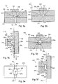
Fig. 1 is a perspective view of a device for the interlacing of a yarn according to this invention, represented in enlarged form; -
Fig. 2 is a first section view, along the plane corresponding to the line II-II, of the interlacing device of the invention ofFig. 1 , shown in its assembled form; -
Fig. 3 is a second section view, along the plane corresponding to the line III-III, of the interlacing device ofFig. 1 ; -
Fig. 4 is a frontal view, along the plane corresponding to the line IV-IV, of the interlacing device ofFig. 1 ; and -
Figs. 5a-5f are sections and views of further embodiments of the interlacing device of the invention. - With reference to
Figs. 1 and4 , a device for air interlacing of a yarn Y, produced according to this invention, is generically designated with thenumeral 10, and is for example integrated in a more complex texturizing unit, of known type and therefore only referred to here only summarily and not represented in the drawings. - In
Fig. 1 , theinterlacing device 10 is represented in broken-down or exploded form and defines alongitudinal axis 11, along which the yarn Y, as it advances at a given feed speed V in the direction indicated by anarrow 18, accedes to and completely traverses thedevice 10, where it is interlaced. - Preferably the yarn Y, which is produced in a known way by a production unit operating before the
device 10, is of synthetic type and is formed by numerous filaments. - The portion of yarn Y, coming from a previous station in the texturizing unit and which accedes to the
device 10 in which it undergoes the interlacing operation, is indicated with Y' and has a non-interlaced structure, i.e. it is essentially without cohesion, in which the filaments are disposed and oriented in a simple, fairly regular way. - The portion of yarn Y, which has already undergone the interlacing operation and which is released from the
device 10 towards other stations of the texturizing unit, is indicated with Y", and has instead its filaments in a complex and interlaced structure. - In particular the portion Y", coming out of the
device 10, is characterized along its length by a succession of fine zones, or knots, indicated with Y1, in which the bonds between the filaments made by thedevice 10 are concentrated, and thick zones, indicated with Y2, in which these bonds have not formed, and are therefore practically missing, or have been formed to a lesser extent. - The knots Y1 are reciprocally spaced out along the yarn Y according to a pitch which, as a result of the interlacing operation produced by the
device 10, is substantially constant. - The structure of the
interlacing device 10 is, according to a known concept, of an opening type, and is formed essentially by two bodies or blocks or main parts, respectively afirst body 12 and asecond body 13, suitable for being opened and closed with respect to one another, in particular to permit introduction of the yarn Y through thedevice 10, and also access to the inside of thedevice 10, for instance for maintenance and cleaning purposes. - The two
bodies flat contact surface 15, thanks to known type fastening and reference means. - For clarity's sake, these known fastening means are depicted in
Fig. 1 with twoplugs 14, represented by the dot and dash line and suitable for cooperating withcorresponding holes 14a formed on thebodies - The two
bodies Figs. 2-4 , define, along the commonflat contact surface 15, aninterlacing duct 21 for the yarn Y, extending along theaxis 11, and formed by afirst entrance channel 22, asecond exit channel 23, and anintermediate interlacing chamber 24, also called turbulence chamber, arranged between theentrance channel 22 and theexit channel 23. - The
first entrance channel 22 and thesecond exit channel 23 are provided respectively for receiving, at the entrance to thedevice 10, the portion Y', to be interlaced, of the yarn Y, and for releasing, at the exit of thedevice 10, the portion Y" of the yarn Y, after it has been interlaced. - In addition, as is clearly shown in the drawings and in particular in
Fig. 3 , thefirst entrance channel 22 and thesecond exit channel 23 preferably have a respective transverse section, on the plane normal to theaxis 11 i.e. to the feeding direction of the yarn Y along theduct 21, which is less than the transverse section of theintermediate interlacing chamber 24, again on this plane. - The interlacing
chamber 24 is defined and delimited, along the interlacingduct 21, by two opposite walls, respectively 24a and 24b, also called emitting wall and deflecting wall, the former of which made in thefirst body 12 and the second in thesecond body 13. - A
nozzle 26, for the emission of a continuous jet of compressed air inside the volume defined by theinterlacing chamber 24, is made in thefirst body 12 and opens onto theinterlacing chamber 24, along therelative wall 24a. - The compressed air that feeds the
nozzle 26 at a nominal pressure Pn to generate the corresponding jet of compressed air is produced and supplied continuously, as indicated by anarrow 27, by means of a known type of compressed air plant, not depicted in any of the drawings, which is adapted to be suitably controlled in order to maintain the compressed air that feeds thenozzle 26 at the nominal pressure Pn in time. - On this subject it should be added that, in the context of this invention, the term air is to be understood as also indicating other fluids, liquid or gaseous, capable in any event of creating phenomena of turbulence around the yarn, that are suitable for interlacing it.
- The
nozzle 26 is defined by a cylindrical hole, of diameter Ø1, substantially oriented along arespective axis 26a in a direction perpendicular to theaxis 11 of thedevice 10, and is also disposed in a central and symmetrical position with respect to the internal volume of the interlacingchamber 24. - According to a key and essential characteristic of this invention, the
wall 24b, which delimits the interlacingchamber 24 and is arranged in front of thenozzle 26 for receiving and deflecting the corresponding jet of compressed air in order to create the turbulence effect inside thesame chamber 24, as better explained in the following, has a special concave shape which is defined by a concave surface on both the transverse and longitudinal planes with respect to theaxis 11, i.e. to yarn Y feeding path through thedevice 10. - In addition, the
wall 24a of theturbulence chamber 24, opposite theconcave wall 24b and bearing thenozzle 26, in turn has a flat shape defined by a flat surface that corresponds to thecontact plane 15 between the twobodies wall 24b. - Accordingly, in this configuration, the interlacing
chamber 24 is completely embedded in thesecond body 13. - The entrance and exit channels, respectively 22 and 23, are in turn carved out completely in the
second body 13, in such a way as to join, at opposite ends, with the concave surface of thewall 24b, thus leaving unaltered the flat surface of thefirst body 12, along the plane ofcontact 15. - Furthermore the
body 12 extends, in the direction of theaxis 11 and externally with respect to the entrance and exitchannels contact 15 as defines theflat wall 24a of the interlacingchamber 24, in such a way as to define aflat guide wall 12a, for guiding and supporting the yarn Y, as it traverses thedevice 10, as will be described better below. - Preferably, the concave shape of the
wall 24b is produced according to a semi-spherical surface, defined by a radius R, wherein this semi-spherical surface is enclosed along the perimeter by the flat surface of thewall 24a, so as to form the interlacingchamber 24, and in which thenozzle 26 opens on the said interlacingchamber 24 in correspondence with the centre of the sphere of radius R defining this semi-spherical surface - The entrance and exit
channels body 13, have in turn, a constant transverse section along theaxis 11, in particular rectangular shape, defined by a width A and a height B, measured respectively along and starting from thecontact plane 15 between the twobodies - The interlacing
device 10 also includes acompartment 32, also called resonance chamber, which is associated with the interlacingchamber 24 and which opens upon the bottom of theconcave wall 24b, in correspondence with the zone of maximum depth of saidconcave wall 24b, i.e. of maximum distance from theflat wall 24a. - In detail, the
resonance chamber 32 extends, through thebody 13 and in a directly substantially in line with theaxis 26a of thenozzle 26, between anopening 32a made in theconcave wall 24b in an area in front of thenozzle 26 and which accordingly puts the volume of theresonance chamber 32 in communication with the volume of the interlacingchamber 24, and an oppositeclosed bottom 32b of theresonance chamber 32, which is made for instance by a closingbody 16 attached to thebody 13. - The area or section of the opening 32° of the
resonance chamber 32 along thewall 24b, is significantly lower than the area or section of the interlacingchamber 24, seen frontally from the side of thenozzle 26, namely in a normal direction to theplane 15, as is clearly shown inFig. 4 . - The function of this
resonance chamber 32 is to accentuate the turbulence and efficacy of the air flow and relative whirls which are set up about the yarn Y, in order to produce the interlacing effect, as better described in the following. - Preferably, in association with the semi-spherical shape of the interlacing
chamber 24, theresonance chamber 32 is formed, according to a cylindrical shape defined by a diameter Ø2 and for a depth P, in the normal direction to the plane ofcontact 15 and along an axis passing through the centre of the sphere of radius R defining thewall 24b, as is clearly visible from the drawings. - By way of example and with the symbols defined below, the table following sets out the preferred ranges, defined by a minimum value Min and a maximum value Max, and the preferred nominal values Nom, for the dimensions of the fundamental parts constituting the interlacing
device 10 and define the shape it will have. - In particular, as discussed in greater depth later on, these numbers refer to the effective dimensions of some prototypes of the interlacing device of the invention, made and thoroughly tested by the Applicant.
- R
- radius of the semi-spherical surface that defines the concave wall of the interlacing chamber;
- A
- width of the entrance and exit channels of the interlacing duct;
- B
- height of the entrance and exit channels;
- Ø1
- diameter of the nozzle for emission of the jet of compressed air;
- Ø2
- diameter of the resonance chamber associated with the interlacing chamber;
- P
- depth of the resonance chamber.
- The
parts device 10, in particular with hard materials suitable to tolerate the rubbing action of the yarn, such as for example special resins and ceramic type materials, or even metallic type materials. - In operation, the yarn Y is fed according to known arrangements at a constant speed V to the interlacing
device 10, along therelative axis 11, so that the yarn Y continuously traverses thedevice 10, being guided in its traversing movement by the entrance and exitchannels wall 12a of thefirst body 12. - At the same time the
nozzle 26 is fed with compressed air, at the nominal pressure Pn, by the corresponding plant, so as to continuously emit a continuous jet ofair 31 towards theconcave wall 24b, in a direction substantially perpendicular to the path of the yarn Y through thedevice 10. - Therefore, the jet of
air 31 intersects the yarn Y, as the latter advances at speed V through the interlacingchamber 24, and is also subjected, in the area of thewall 24b, to a deflection, guided and controlled by the special concave shape of thewall 24b, which acts to direct the main air flow coming from thenozzle 26 backwards, again towards the yarn Y, as indicated by the lines offlow 31a. - In this way the jet of
compressed air 31 activates, inside the interlacingchamber 24 and around the advancing yarn Y, a highly turbulent flow of air, the whirls of which interact with the yarn Y and are such as to determine the entanglement of its filaments, with the resultant transformation of the structure of the yarn Y from a simple filamentary structure to a more complex and interlaced structure, characterized by knots Y2 in correspondence with which the bonds between the filaments of the yarn Y are concentrated. - The
resonance chamber 32, in turn, receives at least a part of the jet of compressed air emitted by thenozzle 31, and in this way cooperates with the interlacingchamber 24, establishing a continuous and rapid exchange of air with the latter-named, so as to accentuate the turbulence of the continuous flow of air which is activated around the yarn Y, in order to produce the effect of entanglement and interlacing between its filaments. - In particular the
resonance chamber 32 operates, in association with the interlacingchamber 24, as a kind of fluodynamic resonator, which establishes resonance conditions that amplify the intensity and efficacy of the air whirls inside thechamber 24. - - From what has been said it will therefore be clear that the characteristics of turbulence and therefore of efficacy of the air flow activated about the yarn Y, in order to produce the interlacing between its filaments, are conditioned and controlled decisively, possibly with the aid of other factors, by the shape of the interlacing
chamber 24, and specifically by the concave shape of the relativesecond wall 24b. - It is also clear that the presence of the
resonance chamber 32 contributes to significantly increasing efficacy of the flow and whirls of air that act on the yarn Y to interlace it. - The turbulent flow about the yarn Y is sustained in time by the jet of air that is constantly input into the
chamber 24, so that the yarn Y is interlaced continuously as it traverses thedevice 10. - The Applicant has not confined itself to identifying the basic concept of the present invention, but has also effectively put it into practice and experimented it thoroughly.
- In particular the Applicant has supported the development and improvement of the invention by producing a series of prototypes that have undergone extensive and in-depth experimentation, and which, inter alia, have served to demonstrate how the interlacing device of the invention permits highly positive results to be obtained, in some aspects exceptional when put in relation to what is obtained with the interlacing devices known today.
- In this context, the tests carried out have shown clearly that the interlacing
device 10, thanks to the special configuration of the interlacingchamber 24, characterized by theconcave wall 24b suitable for receiving and deflecting the jet ofcompressed air 31 emitted by thenozzle 26, and thanks also to the presence of theresonance chamber 32 associated with the interlacingchamber 24, is capable of obtaining a conspicuous saving in the consumption of compressed air, for a like quality of interlaced yarn produced and in particular for a like number of knots per unit of length of yarn interlaced. - For the sake of completeness and by way of example, the data relative
- to some of these results, obtained with a series of prototypes of the
device 10 made in accordance with the dimensional values set out above, are illustrated below in comparison with those of a known device currently on sale.Device type Pressure Pn [bar] Yarn speed V [m/mm] Nozzle diam. Ø1 [mm] Air consumption [m3/hour] Knots Per metre R1 (min. number of knots after stretching by 3%) R2 (min. number of knots after stretching by 6%) Known model already on sale 4.5 750 1.6 6.5 97÷100 97 43 Device of the invention 4.5 750 1.2 3.1 102÷104 98 45 - These figures, though summary and partial, clearly show how the interlacing device of the invention is capable, with respect to the technical solutions currently adopted in the industry, of obtaining a significant and effective saving, quantifiable as about 50%, in terms of consumption of compressed air, for like pressure of the jet of compressed air, and of the other key parameters indicating quality of the production of an interlaced yarn, such as the number of knots produced per unit of length of yarn, and the number of knots after a stretching of the interlaced yarn from 3 to 6%.
- Therefore, in short, the interlacing device of the invention appears capable of producing an interlaced yarn that fully satisfies all the necessary structural and quality requirements, and also of supporting a production capacity equal to that required by the industry, but at a significantly lower cost in terms of consumption of compressed air than the air interlacing devices currently in use.
- Naturally, while remaining within the scope of the present invention, other embodiments of the interlacing device are possible, as alternatives to the preferred embodiment described above and constituted by the interlacing
device 10. - In particular, as already set out in the preceding description, the concavity of the
wall 24b that receives the jet ofcompressed air 31 may be defined by any surface other than a semi-spherical surface, for instance by an elliptical surface or similar. - By way of example, some of these further possible embodiments will be described briefly in the following where, for clarity's sake, the parts of each of these corresponding to those of the interlacing
device 10, will be designated using numerical references progressively incremented by multiples of 100, namely 100 for the first further embodiment, 200 for the second further embodiment, 300 for the third, and so on. - According to a first further embodiment of the interlacing device, designated using the numeral 110 and depicted in section view in
Fig. 5a , the entrance channel 122 and the exit channel 123, arranged to the sides of the interlacingchamber 124 and made in thesecond body 113, have a trapezoidal or similar transverse section, rather than rectangular, in the plane normal to the yarn feeding path Y through thedevice 110. - In a second further embodiment, designated using the
numeral 210 - in
Fig. 5b , the first entrance channel 222, and the second exit channel 223, for feeding to and respectively receiving the yarn Y from the intermediate interlacingchamber 224, have instead a semicircular section. - According to a third further embodiment, designated using the numeral 310 and depicted in section view in
Figs. 5c and 5d , the two channels,entrance 322 andexit 323, are made entirely in thefirst body 312, instead of in thesecond body 313 as in thedevice 10, so that the twochannels chamber 324 without interfering with the relativeconcave surface 324b, made in thesecond body 313, and thefirst wall 324a in turn has agroove 309 that constitutes the continuation of the twochannels chamber 324. - Alternatively, the entrance and exit channels of the yarn may be made, over their entire longitudinal extension, partly in the first body and partly in the second body of the interlacing device.
- Again, according to a fourth further embodiment, designated using the numeral 410 and depicted in
Figs. 5e and 5f , the interlacingchamber 424 exhibits frontally, from the side of thefirst body 412, an elongated shape along an axis of symmetry, selected from either theaxis 411 corresponding to the yarn feeding path Y, or theaxis 408 normal to the path, and consequently, on account of this elongated shape, the interlacingchamber 424 has a first concavity, on the longitudinal plane containing the path of the yarn, and a second concavity, on the plane transversal to the yarn path, in which these two concavities are geometrically different from one another, and for instance at least one of these is defined in section by a semi-elliptical orsimilar profile 407, as depicted inFig. 5f .
| R [mm] | A [mm] | B [mm] | Ø1 [mm] | P [mm] | Ø2 [mm] | |
| Min | 1.4 | 1.5 | 0.5 | 1.0 | 3 | 0.9 |
| Max | 2.5 | 3.5 | 1.5 | 1.4 | 6 | 1.2 |
| Nom | 2 | 2 | 1.25 | 1.1 | 4.5 | 1.0 |
Claims (26)
- Device for air interlacing (10) of a yarn (Y), comprising :an interlacing duct (21, 22, 23, 24) for the passage and guidance of said yarn through said device (10),said interlacing duct (21) having an interlacing chamber (24), a first entrance channel (22) for receiving the yarn (Y) at the entrance of said device and feeding it to said interlacing chamber (24), and a second exit channel (23) for receiving the yarn from said interlacing chamber (24) and releasing it at the exit of said device,said interlacing chamber being delimited by a first emitting wall (24a) bearing a nozzle (26) for the emission of a jet of compressed air (31) inside said interlacing chamber (24), and by a second deflecting wall (24b), opposite the first wall (24a) and having a concave shape, which is suitable for receiving and deflecting the jet of compressed air (31) emitted by the nozzle (26) and intersecting the yarn to be interlaced,said device (10) being characterized in that said interlacing chamber (24) has a transverse section, with respect to the feeding path (11) of the yarn (Y) through the device (10) and as defined by the concave shape of said second deflecting wall, which is greater than that of each of said two channels (22, 23).
- Interlacing device (10) according to claim 1, wherein said second deflecting wall (24b) is concave both on a transverse plane and on a longitudinal plane with respect to feeding direction (11) of the yarn (Y) through said device.
- Interlacing device according to claim 1, wherein said first wall (24a) is defined by a flat surface.
- Device according to any of the previous claims, wherein the concave shape of said second wall (24b) is defined by a spherical surface.
- Device according to claim 4, wherein said spherical surface is constituted by a semi-spherical surface.
- Device according to claim 5, wherein the radius (R) of said spherical surface is between 1.4 and 2.5 mm.
- Device according to claim 6, wherein the radius of said spherical surface is approximately 2 mm.
- Device according to any of the previous claims, wherein said nozzle (26) is defined by a cylindrical hole having a diameter (Ø1) between 1 and 1.4 mm.
- Device according to claim 8, wherein said diameter (Ø1) is approximately 1.1 mm.
- Device according to claim 1, wherein said first and second channels (22, 23) accede to said interlacing chamber (24) by interfering with the respective concave surface (24b)
- Device according to claim 1, wherein at least one (22, 23) of said first and said second channel has a rectangular section.
- Device according to claim 11, wherein the width (A) of said rectangular section is between 1.5 and 3.5 mm, and the height (B) of said rectangular section is between 0.5 and 1.5 mm, with said second concave wall (24b) defined by a semi-spherical surface having a radius (R) between 1.4 and 2.5 mm.
- Device according to claim 1, characterized in that it further comprises a resonance chamber (32) in communication with said interlacing chamber (24) and having the function of facilitating, inside the latter, the creation of air whirls responsible for the interlacing effect.
- Device according to claim 13, wherein said resonance chamber (32) communicates with said interlacing chamber (24) in correspondence with an aperture (32a) formed in said second concave wall (24b), and wherein said resonance chamber (32) extends from said aperture (32a) in a direction substantially in line with the axis (26a) of said emission nozzle (26).
- Device according to claim 13 or 14, wherein said resonance chamber (32) is defined by a cylindrical blind hole.
- Device according to claim 15, wherein the diameter (Ø2) of said cylindrical blind hole is between 0.9 and 1.2 mm and has a depth between 3 and 6 mm.
- Device according to claim 1, formed by a first (12) and a second body (13), each suitable for being opened with respect to the other,
wherein said nozzle (26) for emission of the jet of compressed air is made in said first body (12);
wherein said interlacing duct (21) is made entirely in said second body (13) and further comprises:a first entrance channel (22) for receiving the yarn (Y) at the entrance of said device and feeding to said interlacing chamber (24), ea second exit channel (23) for receiving the yarn from said interlacing chamber (24) and releasing it at the exit of said device; andwherein said first body (12) has a flat surface (15) provided for mating in contact with said second body (13) and defining said first wall (24a) of emission of said interlacing chamber (24). - Device according to claim 17, wherein said first body (12) also defines a guiding wall (12a) for guidance of said yarn (Y) as it traverses said device to be interlaced, said guiding wall (12a) extending externally to the zone of said entrance and exit channels (22, 23) and on the same plane (15) as the flat surface corresponding to said first wall (24a) of said interlacing chamber (24).
- Device (310) according to claim 1, made of a first (312) and a second (313) body, each of which may be opened with respect to the other,
wherein said nozzle (326) for emission of the jet of compressed air is made in said first body (312) and said interlacing chamber (324) is made in said second body (313);
wherein said interlacing duct (321) further comprises:a first entrance channel (322) for receiving the yarn (Y) at the entrance of said device and feeding it to said interlacing chamber (324), anda second exit channel (323) for receiving the yarn from said interlacing chamber (24) and releasing it at the exit of said device; andwherein said first (322) and said second (323) channel are carved in said first body (312) and define a groove (308) in the zone of said interlacing chamber (324) in the relative first emitting wall (324a). - Device (310) according to claim 1, wherein said yarn (Y) is a multifilament synthetic yarn.
- Device (310) according to claim 1, wherein the air interlacing of the yarn (Y) is part of a texturizing process.
- Textile equipment for the processing of one or more yarns comprising at least one air interlacing device according to any of the previous claims.
- Method for air interlacing of a yarn (Y) comprising:- feeding the yarn (Y) along a respective feeding path (11),- intersecting with a jet of compressed air (31) said yarn as it advances, and- deflecting said jet of air (31) intersecting said yarn (Y) by means of a first surface (24b) arranged, with respect to said yarn, at an end opposite that of emission of said jet of compressed air and having a concave shape (24b) on a longitudinal plane and on a transverse plane with respect to the feeding path of said yarn (Y), said first concave surface (24b) being associated with a second surface (24a) arranged, with respect to said yarn (Y), on the side of emission of said jet of compressed air and suitable for receiving the air deflected by said first concave surface (24b) for defining with the latter an interlacing chamber (24) around said yarn (Y) as it advances,wherein said interlacing chamber (24) is dimensioned in such a way to have a transverse section, with respect to the feeding path (11) of the yarn (Y) and as defined by the concave shape of said first surface (24b), which is greater than that of each of two channels (22, 23) arranged along the yarn path respectively for feeding the yarn into and from said interlacing chamber (24).
- Method according to claim 23, wherein said second surface (24a), opposite said first concave surface (24b), is flat.
- Method according to claim 23, wherein said first concave surface (24b) defines a central axis of symmetry about which said concave shape is formed, and
wherein said concave surface is suitable for centrally receiving, on the respective axis of symmetry, said jet of compressed air (31). - Method according to claim 25, wherein the central axis of symmetry of the concave surface (24b) and the axis of emission (26a) of said jet of compressed air (31) substantially coincide and are oriented in a direction substantially perpendicular to said feeding path.
Applications Claiming Priority (2)
| Application Number | Priority Date | Filing Date | Title |
|---|---|---|---|
| IT000004A ITBI20040004A1 (en) | 2004-10-12 | 2004-10-12 | High performance device for the air interlacing of a wire, and relative method |
| PCT/IT2005/000590 WO2006040789A1 (en) | 2004-10-12 | 2005-10-10 | High-performance device for air interlacing of a yarn and corresponding method |
Publications (2)
| Publication Number | Publication Date |
|---|---|
| EP1799892A1 EP1799892A1 (en) | 2007-06-27 |
| EP1799892B1 true EP1799892B1 (en) | 2009-05-06 |
Family
ID=35521154
Family Applications (1)
| Application Number | Title | Priority Date | Filing Date |
|---|---|---|---|
| EP05802392A Not-in-force EP1799892B1 (en) | 2004-10-12 | 2005-10-10 | High-performance device for air interlacing of a yarn and corresponding method |
Country Status (9)
| Country | Link |
|---|---|
| US (1) | US7707699B2 (en) |
| EP (1) | EP1799892B1 (en) |
| JP (1) | JP2008516099A (en) |
| KR (1) | KR20070064623A (en) |
| CN (1) | CN101076626B (en) |
| AT (1) | ATE430823T1 (en) |
| DE (1) | DE602005014373D1 (en) |
| IT (1) | ITBI20040004A1 (en) |
| WO (1) | WO2006040789A1 (en) |
Families Citing this family (8)
| Publication number | Priority date | Publication date | Assignee | Title |
|---|---|---|---|---|
| TWI313310B (en) * | 2005-03-20 | 2009-08-11 | Oerlikon Heberlein Temco Wattwil A | Process and entangling nozzle for the production of knotted yarn |
| IT1393810B1 (en) * | 2009-04-29 | 2012-05-11 | Technores S R L C O Studio Minicucci Pidatella & A | DEVICE FOR THE TREATMENT OF A YARN, A YARN TREATMENT SYSTEM AND A YARN TREATMENT METHOD |
| KR101962601B1 (en) * | 2012-02-20 | 2019-03-28 | 데이진 아라미드 비.브이. | Method and apparatus for entangling yarns |
| ES2750149T3 (en) * | 2013-12-19 | 2020-03-25 | Heberlein Ag | Nozzle and procedure to produce flamed yarn |
| US20180339622A1 (en) * | 2015-05-06 | 2018-11-29 | Schukra Gerätebau Gmbh | System and method of controlling fibers in a mold |
| ITUA20164462A1 (en) * | 2016-06-17 | 2017-12-17 | Sergio Zaglio | INTERLACING DEVICE AND ITS METHOD |
| US11280030B2 (en) * | 2018-05-29 | 2022-03-22 | Nicolas Charles Sear | Textile interlacing jet with smooth yarn channel |
| CN116976127A (en) * | 2023-08-02 | 2023-10-31 | 南京航空航天大学 | Parameterized modeling method for 3D woven composite material |
Family Cites Families (18)
| Publication number | Priority date | Publication date | Assignee | Title |
|---|---|---|---|---|
| US3026597A (en) * | 1960-06-13 | 1962-03-27 | Burlington Industries Inc | Texturing jet |
| US3262179A (en) * | 1964-12-01 | 1966-07-26 | Du Pont | Apparatus for interlacing multifilament yarn |
| DE1685664A1 (en) | 1967-06-19 | 1971-08-19 | Glanzstoff Ag | Device for simultaneous twisting and interlacing |
| US3730413A (en) * | 1971-05-10 | 1973-05-01 | Ici Ltd | Interlacing jet |
| GB1535036A (en) * | 1974-11-28 | 1978-12-06 | Toray Industries | Interlacing multifilament yarn |
| JPS5212362A (en) * | 1975-07-18 | 1977-01-29 | Toray Industries | Fluid treatment apparatus |
| US4644620A (en) * | 1982-12-03 | 1987-02-24 | Murata Kikai Kabushiki Kaisha | Draw texturing and entanglement apparatus for yarn |
| EP0121010B1 (en) * | 1983-03-30 | 1986-12-10 | Toray Industries, Inc. | Apparatus for interlacing multifilament yarn |
| EP0371914A2 (en) * | 1988-11-29 | 1990-06-06 | Heberlein Maschinenfabrik AG | Yarn-texturing jet |
| CH676559A5 (en) | 1989-02-15 | 1991-02-15 | Heberlein & Co Ag | |
| US5157819A (en) * | 1991-03-29 | 1992-10-27 | Basf Corporation | Modular yarn interlacer |
| EP0564400B1 (en) * | 1992-04-03 | 1995-12-06 | Heberlein Maschinenfabrik AG | Apparatus for interlacing multifilament yarns |
| KR100295537B1 (en) * | 1992-09-04 | 2001-12-28 | 히라이 가쯔히꼬 | Sajo's Fluid Treatment System |
| US6134759A (en) * | 1998-03-27 | 2000-10-24 | Toray Industries, Inc. | Apparatus for fluid treatment of yarn and a yarn composed of entangled multifilament |
| EP1207226B1 (en) | 1998-03-30 | 2003-06-04 | Toray Industries, Inc. | Apparatus for fluid treatment of yarn and a yarn composed of entangled multifilament |
| TW584680B (en) * | 1999-05-28 | 2004-04-21 | Inventa Fischer Ag | Device for intermingling, relaxing, and/or thermosetting of filament yarn in a melt spinning process, as well as associated processes and the filament yarn manufactured therewith |
| TW503272B (en) * | 1999-10-06 | 2002-09-21 | Heberlein Fibertechnology Inc | Apparatus for intermingling multifilament yarns |
| TWI313310B (en) * | 2005-03-20 | 2009-08-11 | Oerlikon Heberlein Temco Wattwil A | Process and entangling nozzle for the production of knotted yarn |
-
2004
- 2004-10-12 IT IT000004A patent/ITBI20040004A1/en unknown
-
2005
- 2005-10-10 US US11/664,977 patent/US7707699B2/en not_active Expired - Fee Related
- 2005-10-10 KR KR1020077008180A patent/KR20070064623A/en not_active Application Discontinuation
- 2005-10-10 AT AT05802392T patent/ATE430823T1/en not_active IP Right Cessation
- 2005-10-10 CN CN200580034567XA patent/CN101076626B/en not_active Expired - Fee Related
- 2005-10-10 JP JP2007535328A patent/JP2008516099A/en active Pending
- 2005-10-10 WO PCT/IT2005/000590 patent/WO2006040789A1/en active Application Filing
- 2005-10-10 EP EP05802392A patent/EP1799892B1/en not_active Not-in-force
- 2005-10-10 DE DE602005014373T patent/DE602005014373D1/en active Active
Also Published As
| Publication number | Publication date |
|---|---|
| ITBI20040004A1 (en) | 2005-01-12 |
| ATE430823T1 (en) | 2009-05-15 |
| US20090007403A1 (en) | 2009-01-08 |
| US7707699B2 (en) | 2010-05-04 |
| WO2006040789A1 (en) | 2006-04-20 |
| CN101076626B (en) | 2011-12-07 |
| EP1799892A1 (en) | 2007-06-27 |
| DE602005014373D1 (en) | 2009-06-18 |
| JP2008516099A (en) | 2008-05-15 |
| KR20070064623A (en) | 2007-06-21 |
| CN101076626A (en) | 2007-11-21 |
Similar Documents
| Publication | Publication Date | Title |
|---|---|---|
| EP1799892B1 (en) | High-performance device for air interlacing of a yarn and corresponding method | |
| JP5039546B2 (en) | Apparatus and method for processing filament yarn and star yarn, migration processed yarn, false twisted yarn | |
| US4115988A (en) | Interlaced multifilament yarns | |
| US3005251A (en) | Yarn fluid treatment process and apparatus | |
| US3125793A (en) | Interlaced yarn by multiple utilization of pressurized gas | |
| EP0011441B1 (en) | Yarn treating apparatus | |
| JP2008516099A5 (en) | ||
| US3846968A (en) | Yarn structure and method for producing same | |
| US3688355A (en) | Method and apparatus for preparing non-woven fibrous materials | |
| KR100295537B1 (en) | Sajo's Fluid Treatment System | |
| RU2316623C2 (en) | Nozzle-type core of looped thread forming apparatus | |
| US6308388B1 (en) | Texturing jet | |
| CN100429340C (en) | Spinning device | |
| CN114318617B (en) | Network composite wire and network method and application thereof | |
| US3097412A (en) | Yarn treating apparatus | |
| EP0811711A2 (en) | Yarn processing method and apparatus | |
| US3422516A (en) | Yarn-treating process | |
| KR101904984B1 (en) | Interlace nozzle for synthetic fiber | |
| JP2679545B2 (en) | Thread fluid treatment device | |
| JP5229117B2 (en) | Multi-filament yarn entanglement imparting device and entanglement imparting method | |
| KR101904978B1 (en) | Interlace nozzle for synthetic fiber | |
| JP3991523B2 (en) | Yarn fluid processing equipment | |
| JPH01192844A (en) | Fluid treating device for multifilament yarn | |
| KR880000026B1 (en) | Making method of synthetic fiber yarns | |
| JP3281863B2 (en) | Interlace nozzle |
Legal Events
| Date | Code | Title | Description |
|---|---|---|---|
| PUAI | Public reference made under article 153(3) epc to a published international application that has entered the european phase |
Free format text: ORIGINAL CODE: 0009012 |
|
| 17P | Request for examination filed |
Effective date: 20070503 |
|
| AK | Designated contracting states |
Kind code of ref document: A1 Designated state(s): AT BE BG CH CY CZ DE DK EE ES FI FR GB GR HU IE IS IT LI LT LU LV MC NL PL PT RO SE SI SK TR |
|
| DAX | Request for extension of the european patent (deleted) | ||
| GRAP | Despatch of communication of intention to grant a patent |
Free format text: ORIGINAL CODE: EPIDOSNIGR1 |
|
| GRAS | Grant fee paid |
Free format text: ORIGINAL CODE: EPIDOSNIGR3 |
|
| GRAA | (expected) grant |
Free format text: ORIGINAL CODE: 0009210 |
|
| AK | Designated contracting states |
Kind code of ref document: B1 Designated state(s): AT BE BG CH CY CZ DE DK EE ES FI FR GB GR HU IE IS IT LI LT LU LV MC NL PL PT RO SE SI SK TR |
|
| REG | Reference to a national code |
Ref country code: GB Ref legal event code: FG4D |
|
| REG | Reference to a national code |
Ref country code: CH Ref legal event code: EP |
|
| REG | Reference to a national code |
Ref country code: IE Ref legal event code: FG4D |
|
| REF | Corresponds to: |
Ref document number: 602005014373 Country of ref document: DE Date of ref document: 20090618 Kind code of ref document: P |
|
| REG | Reference to a national code |
Ref country code: CH Ref legal event code: NV Representative=s name: MICHELI & CIE SA |
|
| PG25 | Lapsed in a contracting state [announced via postgrant information from national office to epo] |
Ref country code: ES Free format text: LAPSE BECAUSE OF FAILURE TO SUBMIT A TRANSLATION OF THE DESCRIPTION OR TO PAY THE FEE WITHIN THE PRESCRIBED TIME-LIMIT Effective date: 20090817 Ref country code: FI Free format text: LAPSE BECAUSE OF FAILURE TO SUBMIT A TRANSLATION OF THE DESCRIPTION OR TO PAY THE FEE WITHIN THE PRESCRIBED TIME-LIMIT Effective date: 20090506 Ref country code: LT Free format text: LAPSE BECAUSE OF FAILURE TO SUBMIT A TRANSLATION OF THE DESCRIPTION OR TO PAY THE FEE WITHIN THE PRESCRIBED TIME-LIMIT Effective date: 20090506 Ref country code: AT Free format text: LAPSE BECAUSE OF FAILURE TO SUBMIT A TRANSLATION OF THE DESCRIPTION OR TO PAY THE FEE WITHIN THE PRESCRIBED TIME-LIMIT Effective date: 20090506 Ref country code: PT Free format text: LAPSE BECAUSE OF FAILURE TO SUBMIT A TRANSLATION OF THE DESCRIPTION OR TO PAY THE FEE WITHIN THE PRESCRIBED TIME-LIMIT Effective date: 20090906 |
|
| NLV1 | Nl: lapsed or annulled due to failure to fulfill the requirements of art. 29p and 29m of the patents act | ||
| PG25 | Lapsed in a contracting state [announced via postgrant information from national office to epo] |
Ref country code: LV Free format text: LAPSE BECAUSE OF FAILURE TO SUBMIT A TRANSLATION OF THE DESCRIPTION OR TO PAY THE FEE WITHIN THE PRESCRIBED TIME-LIMIT Effective date: 20090506 Ref country code: NL Free format text: LAPSE BECAUSE OF FAILURE TO SUBMIT A TRANSLATION OF THE DESCRIPTION OR TO PAY THE FEE WITHIN THE PRESCRIBED TIME-LIMIT Effective date: 20090506 Ref country code: PL Free format text: LAPSE BECAUSE OF FAILURE TO SUBMIT A TRANSLATION OF THE DESCRIPTION OR TO PAY THE FEE WITHIN THE PRESCRIBED TIME-LIMIT Effective date: 20090506 Ref country code: SE Free format text: LAPSE BECAUSE OF FAILURE TO SUBMIT A TRANSLATION OF THE DESCRIPTION OR TO PAY THE FEE WITHIN THE PRESCRIBED TIME-LIMIT Effective date: 20090806 Ref country code: IS Free format text: LAPSE BECAUSE OF FAILURE TO SUBMIT A TRANSLATION OF THE DESCRIPTION OR TO PAY THE FEE WITHIN THE PRESCRIBED TIME-LIMIT Effective date: 20090906 Ref country code: SI Free format text: LAPSE BECAUSE OF FAILURE TO SUBMIT A TRANSLATION OF THE DESCRIPTION OR TO PAY THE FEE WITHIN THE PRESCRIBED TIME-LIMIT Effective date: 20090506 |
|
| PG25 | Lapsed in a contracting state [announced via postgrant information from national office to epo] |
Ref country code: EE Free format text: LAPSE BECAUSE OF FAILURE TO SUBMIT A TRANSLATION OF THE DESCRIPTION OR TO PAY THE FEE WITHIN THE PRESCRIBED TIME-LIMIT Effective date: 20090506 Ref country code: DK Free format text: LAPSE BECAUSE OF FAILURE TO SUBMIT A TRANSLATION OF THE DESCRIPTION OR TO PAY THE FEE WITHIN THE PRESCRIBED TIME-LIMIT Effective date: 20090506 Ref country code: CZ Free format text: LAPSE BECAUSE OF FAILURE TO SUBMIT A TRANSLATION OF THE DESCRIPTION OR TO PAY THE FEE WITHIN THE PRESCRIBED TIME-LIMIT Effective date: 20090506 Ref country code: RO Free format text: LAPSE BECAUSE OF FAILURE TO SUBMIT A TRANSLATION OF THE DESCRIPTION OR TO PAY THE FEE WITHIN THE PRESCRIBED TIME-LIMIT Effective date: 20090506 |
|
| PG25 | Lapsed in a contracting state [announced via postgrant information from national office to epo] |
Ref country code: BE Free format text: LAPSE BECAUSE OF FAILURE TO SUBMIT A TRANSLATION OF THE DESCRIPTION OR TO PAY THE FEE WITHIN THE PRESCRIBED TIME-LIMIT Effective date: 20090506 Ref country code: SK Free format text: LAPSE BECAUSE OF FAILURE TO SUBMIT A TRANSLATION OF THE DESCRIPTION OR TO PAY THE FEE WITHIN THE PRESCRIBED TIME-LIMIT Effective date: 20090506 |
|
| PLBE | No opposition filed within time limit |
Free format text: ORIGINAL CODE: 0009261 |
|
| STAA | Information on the status of an ep patent application or granted ep patent |
Free format text: STATUS: NO OPPOSITION FILED WITHIN TIME LIMIT |
|
| PG25 | Lapsed in a contracting state [announced via postgrant information from national office to epo] |
Ref country code: BG Free format text: LAPSE BECAUSE OF FAILURE TO SUBMIT A TRANSLATION OF THE DESCRIPTION OR TO PAY THE FEE WITHIN THE PRESCRIBED TIME-LIMIT Effective date: 20090806 |
|
| 26N | No opposition filed |
Effective date: 20100209 |
|
| PG25 | Lapsed in a contracting state [announced via postgrant information from national office to epo] |
Ref country code: MC Free format text: LAPSE BECAUSE OF NON-PAYMENT OF DUE FEES Effective date: 20091031 |
|
| REG | Reference to a national code |
Ref country code: IE Ref legal event code: MM4A |
|
| PG25 | Lapsed in a contracting state [announced via postgrant information from national office to epo] |
Ref country code: GR Free format text: LAPSE BECAUSE OF FAILURE TO SUBMIT A TRANSLATION OF THE DESCRIPTION OR TO PAY THE FEE WITHIN THE PRESCRIBED TIME-LIMIT Effective date: 20090807 Ref country code: IE Free format text: LAPSE BECAUSE OF NON-PAYMENT OF DUE FEES Effective date: 20091010 |
|
| PG25 | Lapsed in a contracting state [announced via postgrant information from national office to epo] |
Ref country code: IT Free format text: LAPSE BECAUSE OF FAILURE TO SUBMIT A TRANSLATION OF THE DESCRIPTION OR TO PAY THE FEE WITHIN THE PRESCRIBED TIME-LIMIT Effective date: 20090506 |
|
| PG25 | Lapsed in a contracting state [announced via postgrant information from national office to epo] |
Ref country code: LU Free format text: LAPSE BECAUSE OF NON-PAYMENT OF DUE FEES Effective date: 20091010 |
|
| PG25 | Lapsed in a contracting state [announced via postgrant information from national office to epo] |
Ref country code: HU Free format text: LAPSE BECAUSE OF FAILURE TO SUBMIT A TRANSLATION OF THE DESCRIPTION OR TO PAY THE FEE WITHIN THE PRESCRIBED TIME-LIMIT Effective date: 20091107 |
|
| PG25 | Lapsed in a contracting state [announced via postgrant information from national office to epo] |
Ref country code: TR Free format text: LAPSE BECAUSE OF FAILURE TO SUBMIT A TRANSLATION OF THE DESCRIPTION OR TO PAY THE FEE WITHIN THE PRESCRIBED TIME-LIMIT Effective date: 20090506 |
|
| PG25 | Lapsed in a contracting state [announced via postgrant information from national office to epo] |
Ref country code: CY Free format text: LAPSE BECAUSE OF FAILURE TO SUBMIT A TRANSLATION OF THE DESCRIPTION OR TO PAY THE FEE WITHIN THE PRESCRIBED TIME-LIMIT Effective date: 20090506 |
|
| PGFP | Annual fee paid to national office [announced via postgrant information from national office to epo] |
Ref country code: DE Payment date: 20121109 Year of fee payment: 8 Ref country code: FR Payment date: 20121122 Year of fee payment: 8 |
|
| PGFP | Annual fee paid to national office [announced via postgrant information from national office to epo] |
Ref country code: GB Payment date: 20121026 Year of fee payment: 8 |
|
| PGFP | Annual fee paid to national office [announced via postgrant information from national office to epo] |
Ref country code: CH Payment date: 20131112 Year of fee payment: 9 |
|
| GBPC | Gb: european patent ceased through non-payment of renewal fee |
Effective date: 20131010 |
|
| REG | Reference to a national code |
Ref country code: DE Ref legal event code: R119 Ref document number: 602005014373 Country of ref document: DE Effective date: 20140501 |
|
| PG25 | Lapsed in a contracting state [announced via postgrant information from national office to epo] |
Ref country code: GB Free format text: LAPSE BECAUSE OF NON-PAYMENT OF DUE FEES Effective date: 20131010 |
|
| REG | Reference to a national code |
Ref country code: FR Ref legal event code: ST Effective date: 20140630 |
|
| PG25 | Lapsed in a contracting state [announced via postgrant information from national office to epo] |
Ref country code: DE Free format text: LAPSE BECAUSE OF NON-PAYMENT OF DUE FEES Effective date: 20140501 Ref country code: FR Free format text: LAPSE BECAUSE OF NON-PAYMENT OF DUE FEES Effective date: 20131031 |
|
| REG | Reference to a national code |
Ref country code: CH Ref legal event code: PL |
|
| PG25 | Lapsed in a contracting state [announced via postgrant information from national office to epo] |
Ref country code: CH Free format text: LAPSE BECAUSE OF NON-PAYMENT OF DUE FEES Effective date: 20141031 Ref country code: LI Free format text: LAPSE BECAUSE OF NON-PAYMENT OF DUE FEES Effective date: 20141031 |