EP0811711A2 - Yarn processing method and apparatus - Google Patents
Yarn processing method and apparatus Download PDFInfo
- Publication number
- EP0811711A2 EP0811711A2 EP97303861A EP97303861A EP0811711A2 EP 0811711 A2 EP0811711 A2 EP 0811711A2 EP 97303861 A EP97303861 A EP 97303861A EP 97303861 A EP97303861 A EP 97303861A EP 0811711 A2 EP0811711 A2 EP 0811711A2
- Authority
- EP
- European Patent Office
- Prior art keywords
- yarn
- duct
- fluid
- path
- inlet
- Prior art date
- Legal status (The legal status is an assumption and is not a legal conclusion. Google has not performed a legal analysis and makes no representation as to the accuracy of the status listed.)
- Withdrawn
Links
Images

Classifications
-
- D—TEXTILES; PAPER
- D02—YARNS; MECHANICAL FINISHING OF YARNS OR ROPES; WARPING OR BEAMING
- D02J—FINISHING OR DRESSING OF FILAMENTS, YARNS, THREADS, CORDS, ROPES OR THE LIKE
- D02J1/00—Modifying the structure or properties resulting from a particular structure; Modifying, retaining, or restoring the physical form or cross-sectional shape, e.g. by use of dies or squeeze rollers
- D02J1/08—Interlacing constituent filaments without breakage thereof, e.g. by use of turbulent air streams
Definitions
- This invention relates to a method of processing textile yarn and apparatus for performing the method, and in particular to apparatus for creating the desired characteristics in a textured yarn in preparation for subsequent knitting, weaving or otherwise forming into a fabric. More particularly, the invention relates to a method and apparatus for intermingling and reducing the torque in false twist textured multifilament yarn.
- Another problem associated with such yarn is that it still retains some 'twist liveliness' or residual torque, and this can lead to 'snarls' in the yarn which may reduce the efficiency of fabric production and/or impair the quality of a fabric made from the yarn.
- Apparatus for such a purpose comprises a nozzle having a yarn duct, usually circular in cross-section, extending through the nozzle, into which duct one or more air jets impinge radially, i.e. transversely of the travelling yarn, for example as shown in EP-A-0140526.
- this type of nozzle has no torque reducing or 'de-torque' effect on the yarn, and this process does not mitigate any of the problems associated with residual torque and can even worsen the snarling effect.
- the invention provides a method of processing a multifilament false-twisted textile yarn, comprising guiding a false-twisted yarn through a duct along a yarn path, directing fluid into the duct in a direction transverse of the yarn path whereby the yarn path is substantially central of the incoming fluid flow to cause intermingling the filaments of the yarn, and simultaneously directing the fluid to flow swirl around the yarn path to reduce the residual torque in the yarn.
- the method may comprise directing two fluid jets in opposed substantially parallel overlapping directions, but which are offset relative to each other on opposed sides of the yarn path to direct the fluid flow to swirl around the yarn path.
- the method may comprise directing the fluid towards a substantially planar base surface of the duct which is opposed to an inlet for the fluid into the duct and which is inclined laterally of the yarn duct out of the perpendicular to the direction of the inlet to direct the fluid flow to swirl around the yarn path.
- the yarn may be guided under tension adjacent the fluid inlet to facilitate intermingling of the filaments and false twisting of the yarn.
- the fluid may be directed perpendicularly to the yarn path, or in a direction having a component in the forwarding direction of the yarn through the duct.
- the invention also provides apparatus for performing the above method, comprising an elongate body having a yarn duct providing a yarn path extending longitudinally therethrough, a fluid supply communicating with the yarn duct and operable to direct fluid in a direction transversely of the yarn path towards a base surface of the duct, whereby the yarn path is substantially central of the flow of fluid to cause intermingling of the filaments of the yarn, and means directing the fluid flow to swirl around the yarn path simultaneously to reduce the residual torque in the yarn.
- the apparatus may comprise two fluid inlets disposed in opposed substantially parallel overlapping directions so as to effect intermingling of the filaments, but which are offset relative to each other on opposed sides of the yarn path to direct the fluid flow to swirl around the yarn path.
- the duct may have an inlet for the fluid into the duct, and the base surface may be substantially planar and inclined laterally of the yarn duct out of the perpendicular to the direction of the fluid inlet to direct the fluid flow to swirl around the yarn path.
- the fluid inlet may be perpendicular to the yarn path or may be inclined in the forwarding direction of the yarn through the duct. There may be provided a plurality of fluid inlets spaced along the duct.
- the yarn duct may be substantially triangular in cross-section, in which case the fluid inlet may communicate with the yarn duct at a location at an apex of the triangle opposed to the base surface and between two side surfaces.
- a parameter of the apparatus by means of which the de-torque effect on the yarn being processed may be varied is the angle of the base surface relative to the perpendicular to the direction of the fluid inlet. This angle may lie in the range 2° to 45°, and may be substantially 20°.
- the apparatus may comprise a yarn guide located adjacent the upstream end of the yarn duct, and may comprise a second yarn guide adjacent the downstream end of the yarn duct.
- the yarn guides may be disposed to guide a running yarn through the yarn duct so that the yarn path lies adjacent the location of the fluid inlet.
- parameters of the apparatus that will affect the interlacing and de-torque effects of the apparatus are the height of the yarn duct between the air inlet and the base surface, and the diameter of the fluid inlet. Such parameters may be chosen to create the desired interlace and de-torque characteristics in the particular yarn being processed, and may be between 1 mm and 4 mm, e.g. 2 mm; and between 1 mm and 2.5 mm, e.g. 1.65 mm, respectively.
- the apparatus may have a yarn threading slot extending longitudinally of the body and communicating with the exterior of the body and the yarn duct.
- the threading slot may communicate with the yarn duct at a position that is substantially radially central of a fluid inlet that it intersects, or may be in a side surface at a second location adjacent the fluid inlet, and the second location may be between the fluid inlet and the edge of the base surface nearest the fluid inlet.
- the yarn threading slot may have curved profile between the second location and an inlet end at which it communicates with the exterior of the body. The inlet end may be enlarged relative to the width of the yarn threading slot.
- an intermingling and torque reduction device comprises a cylindrical body 10 with a central axial through bore forming a yarn duct 2.
- a device 10 is to be placed after a second heater of a conventional double heater false twist texturing machine.
- the body 10 has a V-shaped channel 3 formed on its exterior surface.
- the channel 3 is offset laterally from the longitudinal axis of, or yarn path 11 through the body 10 so that walls 4 of the channel 3 are of different lengths.
- the walls 4 are approximately mutually perpendicular, and converge downwardly to an apex 5 that is connected to the yarn duct 2 by means of a constricted threading slot 6.
- the slot 6 has an arcuate profile that terminates at the yarn duct 2.
- each air inlet bore 8, 9 is substantially parallel and are vertically offset from each other by a small distance indicated by the letter Z in Figure 1.
- the longitudinal axis of each air inlet bore 8, 9 is also vertically offset from the yarn path 11.
- the threading slot 6 is positioned so that it meets the yarn duct 2 at a position central to the air inlet bore 9 as can be seen from Figure 2.
- a false twisted yarn (not shown) to be treated is passed axially through the yarn duct 2 where it is subjected to air streams issuing from air inlet bores 8, 9.
- the yarn is positioned in the duct 2 by feeding it through the constricted threading slot 6, which is shaped so that escape from the duct 2 under the influence of the air stream is unlikely.
- the air streams impinge on the yarn intermingling of the filaments is effected by virtue of the air streams being in opposition.
- the mutual offset of the air streams causes a swirling action in the yarn duct that effects untwisting of the yarn and therefore a reduction in its residual torque.
- the position and size of the opposed air inlets 8, 9 can be designed with precision and predictability to provide the desired degree of intermingling and torque reduction, and therefore improved product characteristics.
- the dimensions of the apparatus are dependent on the yarn titre and desired characteristics.
- the diameter of the yarn duct 2 is typically in the range 0.8 to 4.0mm.
- the diameter of the air inlet bores is typically between 0.4 and 2.5mm.
- the offset between the longitudinal axes of the air inlet bores typically in the range 0.2 to 1.2mm.
- Jet type Jet feature 1 2 3 Air inlet bore dia (mm) 0.6 1.2 1.7 Number of air inlets 2 2 2 Air inlet bore offset (mm) 0.25 0.2 0.3 Yarn duct dia (mm) 1.4 2.0 2.8 Yarn duct length (mm) 15 15 20
- the parameters indicated for jet type 1 can be used to produce a yarn with low residual torque and a low level of intermingling. Alternatively if it is desired to produce a 1/150 denier yarn at high speed with low residual torque and a medium to high level of interlace, the parameters indicated by jet type 2 might be selected. By selecting the air pressure of the stream supplied a well intermingled yarn with low residual torque is provided.
- the parameters for jet type 3 may be used for low residual torque and a medium to high level of intermingling in a 1/300 denier yarn.
- the air inlet bores 8,9 may be other than circular in cross-section if desired. Furthermore, they may be inclined in the forwarding direction of the yarn as shown in Figure 3. In this case the air inlet bores 108, 109 are inclined at an angle B which may be up to 15° to enable the air streams to assist the passage of the yarn through the duct 2, thereby eliminating the tendency of the streams to add tension to the yarn.
- a nozzle apparatus 40 which comprises an elongate body 12 having a yarn duct 13 providing a yarn path 11 extending longitudinally through the body 12.
- the yarn duct 13 is of substantially triangular cross-section formed by two side surfaces 15, 16 and a substantially planar base surface 17.
- An air inlet 18 communicates with the yarn duct 13 at a location 19, which is an apex of the triangle opposed to the base surface 17, and in an axial direction 20 which is transverse to the yarn path 11.
- the base surface 17 is inclined at an angle A laterally of the yarn duct 13 out of the perpendicular 21 to the axial direction 20 of the air inlet 18.
- the angle A is chosen in the range 5° to 45° to give the required de-torque effect, and is preferably approximately 20°.
- the nozzle body 12 has a yarn threading slot 22 extending longitudinally of the body 12 and communicating with the yarn duct 13 and the exterior of the body 12.
- the threading slot 22 communicates with the yarn duct 13 in the side surface 16 at a second location 23 adjacent the air inlet 18.
- the second location 23 is in the shorter side surface 16 and the slot 22 has curved profile between the second location 23 and an inlet end 24 at which it communicates with the exterior of the nozzle body 12.
- the inlet end 24 is enlarged relative to the width of the yarn threading slot 22.
- Yarn guides 25 are disposed adjacent the inlet and outlet ends of the nozzles 40, 26, and are positioned so as to guide the running yarn 14 through the duct 13 along the path 11 adjacent the inlet location 19 of the air inlet 18.
- the air issuing from the air inlet 18 impinges on the yarn 14 and has a high intensity intermingling effect on the yarn 14.
- the force of the air on the yarn 14 pushes it towards the base surface 17.
- the air is then directed by the inclined base surface 17 towards the longer side surface 15, thereby creating a rotating airflow which has a false twisting or de-torquing effect on the yarn 14.
- the intermingling effect on the yarn 14 is intermittent so that node points are created, spaced along the length of the yarn 14 at regular intervals determined by the air pressure used and the tension in the yarn 14.
- the other parameters that affect the degree of interlacing and the spacing of the nodes are the diameter of the air inlet 18 and the distance of the air inlet location 19 from the base surface 17.
- these dimensions may be approximately 1.65 mm and 2 mm respectively, but generally may lie in the ranges 1 to 2.5mm and 1 to 4mm respectively.
- Figs 6 and 7 show a nozzle 26 which is identical to the nozzle 40 described above except in two respects.
- the nozzle 26 has a yarn duct 13 which is substantially semi-circular, since the shape of the side walls 15, 16 is not critical.
- the air inlet 18 is angled relative to the longitudinal direction of the duct 13 as defined by angle B so as to give a feeding action to the yarn 14 running in the direction shown by the arrows at inlet to and outlet from the nozzle 26.
- the angle B may lie in the range 5° and 15° to give a feeding effect but not to reduce significantly the interlacing effect.
- the semi-circular shape of the duct 13 of nozzle 26 may be used with the orthogonal air inlet 18 of nozzle 40, or the triangular shape of the duct 13 of nozzle 40 may be used with the angled air inlet 18 of nozzle 26.
- the tolerance sensitivity of the nozzles 40, 26 is considerably less than that of known nozzles having offset air inlets to create the false twisting effect.
- a false twist textured yarn may be subjected to an intermingling process to provide a consistent and predictable de-torque effect as well as a predictable and consistent high intensity intermingling effect.
Abstract

Description
- This invention relates to a method of processing textile yarn and apparatus for performing the method, and in particular to apparatus for creating the desired characteristics in a textured yarn in preparation for subsequent knitting, weaving or otherwise forming into a fabric. More particularly, the invention relates to a method and apparatus for intermingling and reducing the torque in false twist textured multifilament yarn.
- The process of texturing a synthetic textile yarn, whilst creating many desirable characteristics in the yarn, may create some undesirable characteristics for certain applications of the yarn. False twist texturing a yarn without further treatment creates a stretch yarn suitable for fabrics used in hosiery, swimwear, skiwear and the like. For fabrics requiring less stretch, it is known to subject the textured yarn to a second heating step, on the texturing machine, under a relaxed tension, to retain the 'bulk' but reduce the stretch characteristics of the yarn. A problem with such yarns is that of a lack of cohesion of the filaments which can be damaged during processing and cause unwinding faults or quality problems in subsequent fabric formation and the final fabric. Another problem associated with such yarn is that it still retains some 'twist liveliness' or residual torque, and this can lead to 'snarls' in the yarn which may reduce the efficiency of fabric production and/or impair the quality of a fabric made from the yarn.
- To improve the cohesion of the filaments, it is known to subject the false twist textured yarn to an intermingling process, to create node points in the yarn at which the filaments are 'tied' together.. Apparatus for such a purpose comprises a nozzle having a yarn duct, usually circular in cross-section, extending through the nozzle, into which duct one or more air jets impinge radially, i.e. transversely of the travelling yarn, for example as shown in EP-A-0140526. Unfortunately, this type of nozzle has no torque reducing or 'de-torque' effect on the yarn, and this process does not mitigate any of the problems associated with residual torque and can even worsen the snarling effect. It is known to reduce the residual torque by passing the false twist textured yarn through a nozzle in which the air jet is offset from the centreline of the yarn duct through the nozzle so as to provide a swirling airflow in the duct to give a small 'false twist' to the yarn in a direction opposed to the residual torque. Such an arrangement is described in EP-A-0532458, in which the air jet is tangential to the duct. However, the action of the air jet in such a nozzle tends to separate the filaments and lessen their cohesiveness. These 'de-torque' and intermingling processes may be performed by separate air nozzles, but this is a costly solution, not only because two air nozzles are required, but also because the two types of nozzle operate at significantly different air pressures and hence two manifolds or costly valves are required. For this reason various arrangements of 'combined' nozzles have been devised in an attempt to perform both processes simultaneously. For example, it is known to offset the air jet slightly from the axis of the yarn duct. However, this arrangement provides a only a low intensity intermingling of the yarn filaments whilst at the same time providing a small measure of torque reduction. In addition, such an arrangement is very tolerance sensitive and does not provide consistent or predictable interlacing or de-torque effects, particularly at high yarn throughput speeds.
- It is an object of the present invention to provide a method, and apparatus suitable for performing that method, in which there is created in a false twist textured yarn a consistent and predictable de-torque effect, together with a consistent and predictable high intensity interlacing effect.
- The invention provides a method of processing a multifilament false-twisted textile yarn, comprising guiding a false-twisted yarn through a duct along a yarn path, directing fluid into the duct in a direction transverse of the yarn path whereby the yarn path is substantially central of the incoming fluid flow to cause intermingling the filaments of the yarn, and simultaneously directing the fluid to flow swirl around the yarn path to reduce the residual torque in the yarn.
- The method may comprise directing two fluid jets in opposed substantially parallel overlapping directions, but which are offset relative to each other on opposed sides of the yarn path to direct the fluid flow to swirl around the yarn path. Alternatively, the method may comprise directing the fluid towards a substantially planar base surface of the duct which is opposed to an inlet for the fluid into the duct and which is inclined laterally of the yarn duct out of the perpendicular to the direction of the inlet to direct the fluid flow to swirl around the yarn path. In this case, the yarn may be guided under tension adjacent the fluid inlet to facilitate intermingling of the filaments and false twisting of the yarn.
- The fluid may be directed perpendicularly to the yarn path, or in a direction having a component in the forwarding direction of the yarn through the duct.
- The invention also provides apparatus for performing the above method, comprising an elongate body having a yarn duct providing a yarn path extending longitudinally therethrough, a fluid supply communicating with the yarn duct and operable to direct fluid in a direction transversely of the yarn path towards a base surface of the duct, whereby the yarn path is substantially central of the flow of fluid to cause intermingling of the filaments of the yarn, and means directing the fluid flow to swirl around the yarn path simultaneously to reduce the residual torque in the yarn.
- The apparatus may comprise two fluid inlets disposed in opposed substantially parallel overlapping directions so as to effect intermingling of the filaments, but which are offset relative to each other on opposed sides of the yarn path to direct the fluid flow to swirl around the yarn path. Alternatively, the duct may have an inlet for the fluid into the duct, and the base surface may be substantially planar and inclined laterally of the yarn duct out of the perpendicular to the direction of the fluid inlet to direct the fluid flow to swirl around the yarn path. The fluid inlet may be perpendicular to the yarn path or may be inclined in the forwarding direction of the yarn through the duct. There may be provided a plurality of fluid inlets spaced along the duct.
- The yarn duct may be substantially triangular in cross-section, in which case the fluid inlet may communicate with the yarn duct at a location at an apex of the triangle opposed to the base surface and between two side surfaces. A parameter of the apparatus by means of which the de-torque effect on the yarn being processed may be varied is the angle of the base surface relative to the perpendicular to the direction of the fluid inlet. This angle may lie in the
range 2° to 45°, and may be substantially 20°. - The apparatus may comprise a yarn guide located adjacent the upstream end of the yarn duct, and may comprise a second yarn guide adjacent the downstream end of the yarn duct. The yarn guides may be disposed to guide a running yarn through the yarn duct so that the yarn path lies adjacent the location of the fluid inlet.
- Other parameters of the apparatus that will affect the interlacing and de-torque effects of the apparatus are the height of the yarn duct between the air inlet and the base surface, and the diameter of the fluid inlet. Such parameters may be chosen to create the desired interlace and de-torque characteristics in the particular yarn being processed, and may be between 1 mm and 4 mm, e.g. 2 mm; and between 1 mm and 2.5 mm, e.g. 1.65 mm, respectively.
- The apparatus may have a yarn threading slot extending longitudinally of the body and communicating with the exterior of the body and the yarn duct. The threading slot may communicate with the yarn duct at a position that is substantially radially central of a fluid inlet that it intersects, or may be in a side surface at a second location adjacent the fluid inlet, and the second location may be between the fluid inlet and the edge of the base surface nearest the fluid inlet. The yarn threading slot may have curved profile between the second location and an inlet end at which it communicates with the exterior of the body. The inlet end may be enlarged relative to the width of the yarn threading slot.
- The invention will now be further described with reference to the accompanying drawings, in which:-
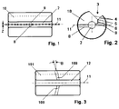
- Figure 1 is a side view of a first embodiment,
- Figure 2 is an end view of the device of Figure 1,
- Figure 3 is a plan view of a second embodiment,
- Figure 4 is an end view of a third embodiment,
- Figure 5 is an end view of a fourth embodiment,
- Figure 6 is a side view of the embodiment of Figure 4, and
- Figure 7 is a side view of the embodiment of Figure 5.
- Referring now to Figures 1 and 2, an intermingling and torque reduction device comprises a
cylindrical body 10 with a central axial through bore forming ayarn duct 2. Such adevice 10 is to be placed after a second heater of a conventional double heater false twist texturing machine. Thebody 10 has a V-shaped channel 3 formed on its exterior surface. Thechannel 3 is offset laterally from the longitudinal axis of, oryarn path 11 through thebody 10 so thatwalls 4 of thechannel 3 are of different lengths. Thewalls 4 are approximately mutually perpendicular, and converge downwardly to an apex 5 that is connected to theyarn duct 2 by means of aconstricted threading slot 6. Theslot 6 has an arcuate profile that terminates at theyarn duct 2. - Midway along the length of the
yarn duct 2 there are opposedair inlet bores yarn duct 2. The air inlet bores 8, 9 are substantially parallel and are vertically offset from each other by a small distance indicated by the letter Z in Figure 1. The longitudinal axis of eachair inlet bore yarn path 11. Thethreading slot 6 is positioned so that it meets theyarn duct 2 at a position central to theair inlet bore 9 as can be seen from Figure 2. - In use, a false twisted yarn (not shown) to be treated is passed axially through the
yarn duct 2 where it is subjected to air streams issuing fromair inlet bores duct 2 by feeding it through theconstricted threading slot 6, which is shaped so that escape from theduct 2 under the influence of the air stream is unlikely. As the air streams impinge on the yarn, intermingling of the filaments is effected by virtue of the air streams being in opposition. At the same time the mutual offset of the air streams causes a swirling action in the yarn duct that effects untwisting of the yarn and therefore a reduction in its residual torque. The position and size of theopposed air inlets yarn duct 2 is typically in the range 0.8 to 4.0mm. The diameter of the air inlet bores is typically between 0.4 and 2.5mm. The offset between the longitudinal axes of the air inlet bores typically in the range 0.2 to 1.2mm. Sets of design parameters for different applications are shown below:Jet type Jet feature 1 2 3 Air inlet bore dia (mm) 0.6 1.2 1.7 Number of air inlets 2 2 2 Air inlet bore offset (mm) 0.25 0.2 0.3 Yarn duct dia (mm) 1.4 2.0 2.8 Yarn duct length (mm) 15 15 20 - The parameters indicated for jet type 1 can be used to produce a yarn with low residual torque and a low level of intermingling. Alternatively if it is desired to produce a 1/150 denier yarn at high speed with low residual torque and a medium to high level of interlace, the parameters indicated by
jet type 2 might be selected. By selecting the air pressure of the stream supplied a well intermingled yarn with low residual torque is provided. The parameters forjet type 3 may be used for low residual torque and a medium to high level of intermingling in a 1/300 denier yarn. The air inlet bores 8,9 may be other than circular in cross-section if desired. Furthermore, they may be inclined in the forwarding direction of the yarn as shown in Figure 3. In this case the air inlet bores 108, 109 are inclined at an angle B which may be up to 15° to enable the air streams to assist the passage of the yarn through theduct 2, thereby eliminating the tendency of the streams to add tension to the yarn. - Referring now to Figures 4 and 6, there is shown a
nozzle apparatus 40 which comprises anelongate body 12 having ayarn duct 13 providing ayarn path 11 extending longitudinally through thebody 12. Theyarn duct 13 is of substantially triangular cross-section formed by twoside surfaces planar base surface 17. Anair inlet 18 communicates with theyarn duct 13 at alocation 19, which is an apex of the triangle opposed to thebase surface 17, and in anaxial direction 20 which is transverse to theyarn path 11. Thebase surface 17 is inclined at an angle A laterally of theyarn duct 13 out of the perpendicular 21 to theaxial direction 20 of theair inlet 18. The angle A is chosen in the range 5° to 45° to give the required de-torque effect, and is preferably approximately 20°. - The
nozzle body 12 has ayarn threading slot 22 extending longitudinally of thebody 12 and communicating with theyarn duct 13 and the exterior of thebody 12. The threadingslot 22 communicates with theyarn duct 13 in theside surface 16 at asecond location 23 adjacent theair inlet 18. To reduce the possibility of theyarn 14 coming out of theyarn threading slot 22 during use of thenozzle 40, thesecond location 23 is in theshorter side surface 16 and theslot 22 has curved profile between thesecond location 23 and aninlet end 24 at which it communicates with the exterior of thenozzle body 12. For ease of threading, theinlet end 24 is enlarged relative to the width of theyarn threading slot 22. - Yarn guides 25 are disposed adjacent the inlet and outlet ends of the
nozzles yarn 14 through theduct 13 along thepath 11 adjacent theinlet location 19 of theair inlet 18. The air issuing from theair inlet 18 impinges on theyarn 14 and has a high intensity intermingling effect on theyarn 14. The force of the air on theyarn 14 pushes it towards thebase surface 17. The air is then directed by theinclined base surface 17 towards thelonger side surface 15, thereby creating a rotating airflow which has a false twisting or de-torquing effect on theyarn 14. As theyarn 14 moves away from theair inlet location 19, the force of the air on it reduces so that the tension in theyarn 14 moves theyarn 14 back towards theinlet location 19, thereby increasing the force of the air on it again. In consequence, the intermingling effect on theyarn 14 is intermittent so that node points are created, spaced along the length of theyarn 14 at regular intervals determined by the air pressure used and the tension in theyarn 14. The other parameters that affect the degree of interlacing and the spacing of the nodes are the diameter of theair inlet 18 and the distance of theair inlet location 19 from thebase surface 17. Typically for 150 denier yarn, these dimensions may be approximately 1.65 mm and 2 mm respectively, but generally may lie in the ranges 1 to 2.5mm and 1 to 4mm respectively. - Figs 6 and 7 show a
nozzle 26 which is identical to thenozzle 40 described above except in two respects. Firstly, thenozzle 26 has ayarn duct 13 which is substantially semi-circular, since the shape of theside walls nozzle 26 theair inlet 18 is angled relative to the longitudinal direction of theduct 13 as defined by angle B so as to give a feeding action to theyarn 14 running in the direction shown by the arrows at inlet to and outlet from thenozzle 26. The angle B may lie in the range 5° and 15° to give a feeding effect but not to reduce significantly the interlacing effect. The semi-circular shape of theduct 13 ofnozzle 26 may be used with theorthogonal air inlet 18 ofnozzle 40, or the triangular shape of theduct 13 ofnozzle 40 may be used with theangled air inlet 18 ofnozzle 26. - Because, in the
nozzles base surface 17 of theyarn duct 13 is substantially planar, the tolerance sensitivity of thenozzles
Claims (14)
- A method of processing a multifilament false-twisted textile yarn (14), comprising guiding a false-twisted yarn (14) through a duct (2, 13) along a yarn path (11), and directing fluid into the duct (2, 13) in a direction transverse of the yarn path (11), characterised in that the yarn path (11) is substantially central of the incoming fluid flow (8, 9, 18) to cause intermingling the filaments of the yarn (14), and by simultaneously directing the fluid flow (8, 9, 18) to swirl around the yarn path (11) to reduce the residual torque in the yarn (14).
- A method according to claim 1, characterised by directing two fluid inlets (8, 9) in opposed substantially parallel overlapping directions, but which are offset relative to each other on opposed sides of the yarn path (11) to direct the fluid flow to swirl around the yarn path (11).
- A method according to claim 1, characterised by directing the fluid towards a substantially planar base surface (17) of the duct (13) which is opposed to an inlet (18) for the fluid into the duct (13), and which is inclined laterally of the duct (13) out of the perpendicular (21) to the direction (20) of the inlet (18) to direct the fluid flow to swirl around the yarn path (11).
- A method according to claim 3, characterised by guiding the yarn (14) under tension adjacent the inlet (18) for the fluid into the duct (13),
- Apparatus for performing the method of claim 1, comprising an elongate body (10, 12) having a yarn duct (2, 13) providing a yarn path (11) extending longitudinally therethrough, a fluid supply (8, 9, 18) communicating with the yarn duct (2, 13) and operable to direct fluid in a direction transversely of the yarn path (11) towards a base surface (17) of the duct (2, 13), characterised in that the yarn path (11) is substantially central of the flow of fluid (8, 9, 18) to cause intermingling of the filaments of the yarn (14), and by means (8, 9,17) directing the fluid flow (8, 9, 18) to swirl around the yarn path (11) simultaneously to reduce the residual torque in the yarn (14).
- Apparatus according to claim 5, characterised in that two fluid inlets (8, 9) are disposed in opposed substantially parallel overlapping directions, but are offset relative to each other on opposed sides of the yarn path (11) to direct the fluid flow to swirl around the yarn path (11).
- Apparatus according to claim 5, characterised in that the duct (13) has an inlet (18) for the fluid into the duct (13), and the base surface (17) is substantially planar and inclined laterally of the yarn duct (13) out of the perpendicular (21) to the direction (20) of the fluid inlet (18) to direct the fluid flow to swirl around the yarn path (11).
- An apparatus according to claim 7, characterised in that the yarn duct (13) is substantially triangular in cross-section.
- An apparatus according to claim 8, characterised in that the fluid inlet (18) communicates with the yarn duct (13) at a location (19) at an apex of the triangle opposed to the base surface (17) and between two side surfaces (15, 16).
- An apparatus according to any one of claims 5 to 9, characterised in that first and second yarn guides (25) are located adjacent the upstream and the downstream ends of the yarn duct (13), and the yarn guides (25) are disposed to guide a running yarn (14) through the yarn duct (13) so that the yarn path (11) lies adjacent the location (19) of the fluid inlet (18).
- An apparatus according to any one of claims 5 to 10, characterised in that a yarn threading slot (6, 22) extends longitudinally of the body (10, 12) and communicates with the yarn duct (2, 13) and the exterior of the body (10, 12).
- An apparatus according to claim 11, characterised in that the yarn threading slot (6, 22) has curved profile between the location (19) at which it communicates with the yarn duct (2, 13) and an inlet end (3, 24) at which it communicates with the exterior of the body (10, 12).
- An apparatus according to claim 11 or claim 12, when dependent on claim 6, characterised in that the threading slot (6) communicates with the yarn duct (2) at a position central of a fluid inlet (9).
- An apparatus according to claim 11 or claim 12, when dependent on claim 7, characterised in that the threading slot (22) communicates with the yarn duct (13) in a side surface (16) at a second location (23) adjacent the fluid inlet (18), and the second location (23) lies between the fluid inlet (18) and the edge of the base surface (17) nearest the fluid inlet (18).
Applications Claiming Priority (4)
| Application Number | Priority Date | Filing Date | Title |
|---|---|---|---|
| GB9611959 | 1996-06-07 | ||
| GBGB9611959.9A GB9611959D0 (en) | 1996-06-07 | 1996-06-07 | Method and device for intermingling and reducing torque in multifilament yarns |
| GBGB9703378.1A GB9703378D0 (en) | 1997-02-18 | 1997-02-18 | Yarn processing apparatus |
| GB9703378 | 1997-02-18 |
Publications (2)
| Publication Number | Publication Date |
|---|---|
| EP0811711A2 true EP0811711A2 (en) | 1997-12-10 |
| EP0811711A3 EP0811711A3 (en) | 1999-09-01 |
Family
ID=26309464
Family Applications (1)
| Application Number | Title | Priority Date | Filing Date |
|---|---|---|---|
| EP97303861A Withdrawn EP0811711A3 (en) | 1996-06-07 | 1997-06-05 | Yarn processing method and apparatus |
Country Status (4)
| Country | Link |
|---|---|
| EP (1) | EP0811711A3 (en) |
| JP (1) | JPH1088437A (en) |
| KR (1) | KR19980069781A (en) |
| TW (1) | TW344003B (en) |
Cited By (7)
| Publication number | Priority date | Publication date | Assignee | Title |
|---|---|---|---|---|
| EP0976856A1 (en) * | 1998-07-04 | 2000-02-02 | Fibreguide Limited | Yarn treatment jet |
| WO2000047804A1 (en) * | 1999-02-08 | 2000-08-17 | Heberlein Fibertechnology, Inc. | Method and device as well as the utilization of the device to produce a blended yarn or a composite yarn |
| WO2000073555A1 (en) * | 1999-05-28 | 2000-12-07 | E.I. Du Pont De Nemours And Company | Methods and apparatus for interlacing filaments and methods of making the apparatus |
| WO2001055488A2 (en) * | 2000-01-26 | 2001-08-02 | Heberlein Fibertechnology, Inc. | Method for false twisting filament yarn and a false twist nozzle consisting of several components |
| US7454816B2 (en) | 1999-06-14 | 2008-11-25 | E.I. Du Pont De Nemours And Company | Stretch break method, apparatus and product |
| US7581376B2 (en) | 2004-02-27 | 2009-09-01 | E.I. Du Pont De Nemours And Company | Spun yarn, and method and apparatus for the manufacture thereof |
| EP3358052A1 (en) * | 2017-02-01 | 2018-08-08 | Oerlikon Textile GmbH & Co. KG | Device for entangling a plurality of individual filaments of a composite yarn |
Citations (6)
| Publication number | Priority date | Publication date | Assignee | Title |
|---|---|---|---|---|
| US3443292A (en) * | 1968-05-31 | 1969-05-13 | Du Pont | Apparatus for interlacing multi-filament yarn |
| US3727274A (en) * | 1971-04-01 | 1973-04-17 | Fiber Industries Inc | Multifilament yarn interlacing device |
| US3750242A (en) * | 1971-06-30 | 1973-08-07 | Celanese Corp | Yarn compacting apparatus |
| US4251904A (en) * | 1978-11-08 | 1981-02-24 | Toray Industries, Inc. | Yarn treating apparatus |
| US4430780A (en) * | 1982-01-11 | 1984-02-14 | International Machinery Sales, Inc. | Fluid flow comingling jet |
| EP0140526A2 (en) * | 1983-08-31 | 1985-05-08 | Fibreguide Limited | Intermining mulifilament yarns |
Family Cites Families (2)
| Publication number | Priority date | Publication date | Assignee | Title |
|---|---|---|---|---|
| US3079745A (en) * | 1960-08-23 | 1963-03-05 | Du Pont | Fluid twiste apparatus for twisting yarn |
| JPH0781223B2 (en) * | 1988-01-21 | 1995-08-30 | 帝人株式会社 | Fluid processing equipment for multiple yarns |
-
1997
- 1997-05-27 TW TW086107156A patent/TW344003B/en active
- 1997-06-02 KR KR1019970022633A patent/KR19980069781A/en not_active Application Discontinuation
- 1997-06-05 EP EP97303861A patent/EP0811711A3/en not_active Withdrawn
- 1997-06-05 JP JP16324497A patent/JPH1088437A/en active Pending
Patent Citations (6)
| Publication number | Priority date | Publication date | Assignee | Title |
|---|---|---|---|---|
| US3443292A (en) * | 1968-05-31 | 1969-05-13 | Du Pont | Apparatus for interlacing multi-filament yarn |
| US3727274A (en) * | 1971-04-01 | 1973-04-17 | Fiber Industries Inc | Multifilament yarn interlacing device |
| US3750242A (en) * | 1971-06-30 | 1973-08-07 | Celanese Corp | Yarn compacting apparatus |
| US4251904A (en) * | 1978-11-08 | 1981-02-24 | Toray Industries, Inc. | Yarn treating apparatus |
| US4430780A (en) * | 1982-01-11 | 1984-02-14 | International Machinery Sales, Inc. | Fluid flow comingling jet |
| EP0140526A2 (en) * | 1983-08-31 | 1985-05-08 | Fibreguide Limited | Intermining mulifilament yarns |
Cited By (10)
| Publication number | Priority date | Publication date | Assignee | Title |
|---|---|---|---|---|
| EP0976856A1 (en) * | 1998-07-04 | 2000-02-02 | Fibreguide Limited | Yarn treatment jet |
| WO2000047804A1 (en) * | 1999-02-08 | 2000-08-17 | Heberlein Fibertechnology, Inc. | Method and device as well as the utilization of the device to produce a blended yarn or a composite yarn |
| WO2000073555A1 (en) * | 1999-05-28 | 2000-12-07 | E.I. Du Pont De Nemours And Company | Methods and apparatus for interlacing filaments and methods of making the apparatus |
| US7454816B2 (en) | 1999-06-14 | 2008-11-25 | E.I. Du Pont De Nemours And Company | Stretch break method, apparatus and product |
| US7559121B2 (en) | 1999-06-14 | 2009-07-14 | E.I. Du Pont De Nemours And Company | Stretch break method and product |
| WO2001055488A2 (en) * | 2000-01-26 | 2001-08-02 | Heberlein Fibertechnology, Inc. | Method for false twisting filament yarn and a false twist nozzle consisting of several components |
| WO2001055488A3 (en) * | 2000-01-26 | 2001-12-27 | Heberlein Fibertechnology Inc | Method for false twisting filament yarn and a false twist nozzle consisting of several components |
| US7581376B2 (en) | 2004-02-27 | 2009-09-01 | E.I. Du Pont De Nemours And Company | Spun yarn, and method and apparatus for the manufacture thereof |
| EP3358052A1 (en) * | 2017-02-01 | 2018-08-08 | Oerlikon Textile GmbH & Co. KG | Device for entangling a plurality of individual filaments of a composite yarn |
| US10988864B2 (en) | 2017-02-01 | 2021-04-27 | Oerlikon Textile Gmbh & Co. Kg | Device for entangling a plurality of individual threads of a composite thread |
Also Published As
| Publication number | Publication date |
|---|---|
| TW344003B (en) | 1998-11-01 |
| EP0811711A3 (en) | 1999-09-01 |
| JPH1088437A (en) | 1998-04-07 |
| KR19980069781A (en) | 1998-10-26 |
Similar Documents
| Publication | Publication Date | Title |
|---|---|---|
| US3822543A (en) | Spun-like yarn and method of manufacturing same | |
| US4115988A (en) | Interlaced multifilament yarns | |
| US4069565A (en) | Process and apparatus for producing textured multifilament yarn | |
| US3125793A (en) | Interlaced yarn by multiple utilization of pressurized gas | |
| US4736578A (en) | Method for forming a slub yarn | |
| JP3126441B2 (en) | Apparatus for blow-texturing at least one multifilament yarn | |
| RU2041982C1 (en) | Device for texturing yarn by false twist method | |
| US4345425A (en) | Process for making bulky textured multifilament yarn | |
| US3443292A (en) | Apparatus for interlacing multi-filament yarn | |
| US5713113A (en) | Device for treating at least one running multifilament yarn | |
| US6701704B2 (en) | Processing textile materials | |
| EP0811711A2 (en) | Yarn processing method and apparatus | |
| US3220082A (en) | Jet apparatus for treatment of textile fibers | |
| US4934134A (en) | Apparatus for randomizing multiple yarn strands | |
| JPS62117830A (en) | Apparatus for production of spun yarn | |
| US4125922A (en) | Jet tangler | |
| US4141122A (en) | Process for producing fluid jet teased, fluffy, hairy yarns from short/medium staple multifiber yarns | |
| US3978558A (en) | Air jet yarn entanglement | |
| US4141121A (en) | Apparatus for producing fluid jet teased yarns from short/medium staple multifiber spun yarns | |
| US4346552A (en) | Bulky textured multifilament yarn | |
| US3537248A (en) | Simultaneously twisting and interlacing a continuous multifilament yarn | |
| SU1764516A3 (en) | System for texturing of thread | |
| US3422516A (en) | Yarn-treating process | |
| US4899426A (en) | Method and apparatus for randomizing multiple yarn strands | |
| US3097412A (en) | Yarn treating apparatus |
Legal Events
| Date | Code | Title | Description |
|---|---|---|---|
| PUAI | Public reference made under article 153(3) epc to a published international application that has entered the european phase |
Free format text: ORIGINAL CODE: 0009012 |
|
| AK | Designated contracting states |
Kind code of ref document: A2 Designated state(s): CH DE GB IT LI |
|
| PUAL | Search report despatched |
Free format text: ORIGINAL CODE: 0009013 |
|
| AK | Designated contracting states |
Kind code of ref document: A3 Designated state(s): AT BE CH DE DK ES FI FR GB GR IE IT LI LU MC NL PT SE |
|
| RIC1 | Information provided on ipc code assigned before grant |
Free format text: 6D 02J 1/08 A, 6D 02G 1/16 B |
|
| 17P | Request for examination filed |
Effective date: 20000225 |
|
| AKX | Designation fees paid |
Free format text: CH DE GB IT LI |
|
| 17Q | First examination report despatched |
Effective date: 20020312 |
|
| GRAP | Despatch of communication of intention to grant a patent |
Free format text: ORIGINAL CODE: EPIDOSNIGR1 |
|
| STAA | Information on the status of an ep patent application or granted ep patent |
Free format text: STATUS: THE APPLICATION IS DEEMED TO BE WITHDRAWN |
|
| 18D | Application deemed to be withdrawn |
Effective date: 20031118 |