EP1207226B1 - Apparatus for fluid treatment of yarn and a yarn composed of entangled multifilament - Google Patents
Apparatus for fluid treatment of yarn and a yarn composed of entangled multifilament Download PDFInfo
- Publication number
- EP1207226B1 EP1207226B1 EP01131058A EP01131058A EP1207226B1 EP 1207226 B1 EP1207226 B1 EP 1207226B1 EP 01131058 A EP01131058 A EP 01131058A EP 01131058 A EP01131058 A EP 01131058A EP 1207226 B1 EP1207226 B1 EP 1207226B1
- Authority
- EP
- European Patent Office
- Prior art keywords
- yarn
- passage
- fluid
- axial line
- outlet
- Prior art date
- Legal status (The legal status is an assumption and is not a legal conclusion. Google has not performed a legal analysis and makes no representation as to the accuracy of the status listed.)
- Expired - Lifetime
Links
Images


Classifications
-
- D—TEXTILES; PAPER
- D02—YARNS; MECHANICAL FINISHING OF YARNS OR ROPES; WARPING OR BEAMING
- D02J—FINISHING OR DRESSING OF FILAMENTS, YARNS, THREADS, CORDS, ROPES OR THE LIKE
- D02J1/00—Modifying the structure or properties resulting from a particular structure; Modifying, retaining, or restoring the physical form or cross-sectional shape, e.g. by use of dies or squeeze rollers
- D02J1/08—Interlacing constituent filaments without breakage thereof, e.g. by use of turbulent air streams
-
- D—TEXTILES; PAPER
- D02—YARNS; MECHANICAL FINISHING OF YARNS OR ROPES; WARPING OR BEAMING
- D02G—CRIMPING OR CURLING FIBRES, FILAMENTS, THREADS, OR YARNS; YARNS OR THREADS
- D02G1/00—Producing crimped or curled fibres, filaments, yarns, or threads, giving them latent characteristics
- D02G1/16—Producing crimped or curled fibres, filaments, yarns, or threads, giving them latent characteristics using jets or streams of turbulent gases, e.g. air, steam
- D02G1/161—Producing crimped or curled fibres, filaments, yarns, or threads, giving them latent characteristics using jets or streams of turbulent gases, e.g. air, steam yarn crimping air jets
Definitions
- the present invention relates to an apparatus for fluid treatment of yarn by forcing fluid into a running multifilament yarn, for specially entangling multifilaments. It further relates to a yarn composed of entangled multifilaments produced by the apparatus.
- Multifilament yarn produced by spinning a high molecular polymer generally has poor filament coherency, requiring treatment to impart coherency.
- Conventional methods for imparting coherency include twisting the yarn, sizing the yarn, and fluid entanglement.
- Fluid entanglement is often used because it is easy to impart desired properties of compactness or bulkiness to the yarn as spun.
- the requisite equipment is simple.
- Fluid entangling devices are often called entangling devices, entangling nozzles or interlacing nozzles, etc.
- the conventional entangling nozzle comprises a nozzle block (NB), a yarn passage (Yp) formed in the nozzle block (NB) and having a yarn inlet (Iy) and a yarn outlet (Oy) in the outer surface of the nozzle block (NB), also a fluid passage (Fp) formed in the nozzle block (NB) and having a fluid inlet (If) in the outer surface of the nozzle block (NB) and a fluid outlet (Of) in the inner wall surface of the yarn passage (Yp).
- the yarn is run at a desired speed and tension, through the yarn passage (Yp), and encounters a fluid (fluid jet) injected at a desired pressure, velocity and flow rate from the fluid passage (Fp).
- a fluid fluid jet
- the yarn is simply called a tangled yarn.
- a compact yarn or a bulky yarn can be produced.
- An entanglement measuring instrument for measuring the degree of entanglement of filaments is known and used.
- a bulkiness measuring instrument is used for that purpose.
- an entangling nozzle in which a cross-sectional configuration and area of the yarn passage (Yp) are changed in the longitudinal direction has been proposed. Furthermore, to obtain a high degree of entanglement, it has been proposed to force a compressive fluid of higher than the critical pressure through a fluid passage (Fp) at a supersonic velocity with a specially formed cross section to a running yarn.
- the fluid passage (Fp) is a thin or fine hole having a diameter of only several millimeters, it is very difficult to form a highly accurate throat in the hole. Accordingly, the entangling capability differs from nozzle to nozzle among the many nozzles produced. As a result, it is an inevitable problem that the entangling capability and degree of yarn entanglement differs from nozzle to nozzle among many entangling nozzles used in production entangled yarns.
- the object of the present invention is to provide an apparatus for tangling multifilament yarn with manufacturing consistency and accuracy, and to produce a plurality of yarns composed of entangled multifilament with small variance of entangling degree from yarn to yarn.
- An apparatus for fluid treatment of yarn according to the present invention to achieve the above object is as follows.
- An apparatus for fluid treatment of yarn comprising a nozzle block (NB), a yarn passage (Yp) formed in the nozzle block (NB) and having a yarn inlet (Iy) and a yarn outlet (Oy) in the outer surface of the nozzle block (NB), and a fluid passage (Fp) formed in the nozzle block (NB) and having a fluid inlet (If) in the outer surface of the nozzle block (NB) and a fluid outlet (Of) in the inner wall surface of the yarn passage (Yp), wherein the fluid passage (Fp) comprises a straight passage (Sp), and an expanding passage (Ep), and wherein
- the fluid passage (Fp) of this apparatus (entangling nozzle) has a straight passage (Sp) with a certain length and an expanding passage (Ep) in succession to it, high pressure portion is formed in the space in contact with the wall surface of the yarn passage (Yp) facing the fluid outlet (Of) of the fluid passage (Fp) and its vicinity, and low pressure portions are formed in the space in contact with the wall surface of the yarn passage (Yp) near the fluid outlet (Of) of the fluid passage (Fp) and its vicinity, which enhaces the filament entangling capability.
- This will be explained later in reference to Fig. 5 in more detail.
- the accuracy in manufacturing the entangling nozzle is further improved, and even if many entangling nozzles are manufactured and used in the same plant, all the entangling nozzles obtained have substantially the same entangling capability.
- the straight progression of the fluid jet by the straight passage (Sp) may become weak, and in this case, the above-mentioned action and effect by the expanding passage (Ep) existing next to the straight passage (Sp) may decrease.
- the fluid jet may flow only toward the yarn inlet (Iy) or yarn outlet (Oy) of the yarn passage (Yp), and in this case, the filament entangling action by the fluid jet declines.
- T ⁇ 15° is more preferable.
- the entangling nozzle can be more easily manufactured, and the manufacturing accuracy can be further improved.
- An apparatus for fluid treatment of yarn wherein the form of the fluid passage (Fp) in a plane perpendicular to the reference plane (BP) and parallel to the direction of the reference line (APYp) is rectangular and the configuration of the yarn passage (Yp) in a plane perpendicular to the reference plane (BP) and perpendicular to the direction of the reference line (APYp) is rectangular.
- the entangling nozzle can be more easily manufactured, and the manufacturing accuracy can be further enhanced. Furthermore, the entangling nozzle can also be easily assembled and disassembled for repair.
- An apparatus for fluid treatment of yarn according to any one of the first to fifth embodiments of the invention, wherein the area of the yarn passage (Yp) in a plane perpendicular to the second axial line (AYp) expands at least at either of the yarn inlet portion containing the yarn inlet (Oy) or the yarn outlet portion containing the yarn outlet (Oy).
- the discharge of the fluid contributed to the entangling treatment from either of or both of the yarn inlet (Iy) and the yarn outlet (Oy) can be promoted. Furthermore, in this relationship, where the treatment conditions are properly selected, the entanglement of filaments becomes bulky, and in this case, the entangling nozzle can be applied to the production of a bulky yarn.
- An apparatus for fluid treatment of yarn which comprises a nozzle block (NB), a yarn passage (Yp) formed in the nozzle block (NB) and having a yarn inlet (Iy) and a yarn outlet (Oy) in the outer surface of the nozzle block (NB), and a fluid passage (Fp) formed in the nozzle block (NB) and having a fluid inlet (If) in the outer surface of the nozzle block (NB) and a fluid outlet (Of) in the inner wall surface of the yarn passage (Yp), wherein the fluid passage (Fp) has
- the major portion of the seventh embodiment of the invention are reflected to the major portion of the first embodiment of the invention and both the embodiments are substantially the same.
- the entangled yarn has filaments entangled each other in good balance, and as desired. Furthermore, the entangled yarns are substantially free from dispersion in entanglement.
- expressions relating to the axial line of the fluid passage Fp, the axial line of the straight passage Sp and the axial line of the yarn passage Yp refer to lines passing through the centers of gravity of the figures formed by the cross sections of the respective passages.
- the apparatus of the present invention it is preferable to form the expanding passage Ep of the fluid passage Fp with a plurality of members. In this case, the manufacturing accuracy of the expanding passage Ep can be improved.
- the wall surface configuration of the expanding passage Ep of the fluid passage Fp in the reference plane BP can be curved, tapered, stepped or formed in any other way, but it is preferable that it is formed in such a manner as to gradually smoothly depart from the first axial line.
- the sectional configuration of the yarn passage Yp in the direction perpendicular to the axial line of the yarn passage Yp can be circular, imperfectly circular, semi-circular, oblong, ellipsoidal, triangular, square, polygonal or of any other form.
- the sectional configuration of the fluid passage Fp in the direction perpendicular to the axial line of the straight passage Sp (the first axial line ASp) can be various, but since it is small in diameter, a rectangle or circle is preferable.
- the number of the fluid passages Fp can be one, two, three or many, and are not limited.
- the number of the fluid passages Fp is determined in relation to the kind of the yarn to be entangled, the desired type of filament entanglement and the magnitude of the energy of the fluid jet.
- the angle formed by the axial line of the straight passage Sp (the first axial line ASp) of the fluid passage Fp and the axial line (the second axial line AYp) of the yarn passage Yp or the reference line APYp is about 30° to 150°.
- an angle of about 60° to 120° is preferable, and about 90° is more preferable.
- an angle of about 10° to 60° is preferable.
- the material of the members used to form the yarn passage Yp and the fluid passage Fp can be any material which is durable in the presence of the running yarn and the fluid jet, and may be metal, ceramic, glass or any other material coated with a hard film.
- the fluid jet used can be any fluid jet of the kind usually used for producing conventional entangled yarns.
- the fluid jet can be at room temperature or heated compressed air or steam, etc.
- the fluid jet is supplied to the fluid passage Fp by a fluid jet supply pipe connected to a supply source at one end and to the fluid inlet If of the fluid passage Fp at the other end.
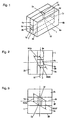
- Fig. 1 is a schematic perspective view showing a first example of the apparatus of the present invention.
- Fig. 2 is a front view of the first example.
- Fig. 3 is a top view of the first example.
- Fig. 4 is a vertical sectional view of the first example.
- an apparatus 1 for fluid treatment of yarn is formed by a nozzle block (NB).
- the nozzle block NB comprises five pieces.
- a right piece 2a and a left piece 2b are positioned with a predetermined space kept between them.
- a bottom piece 3, a top front piece 4a and a top rear piece 4b are positioned between the right and left pieces 2a and 2b.
- the bottom piece 3 and the top front and rear pieces 4a and 4b are positioned with a space kept between them.
- the yarn passage Yp is formed as a space surrounded by the surfaces of the right and left pieces 2a and 2b, the bottom piece 3 and the top front and rear pieces 4a and 4b.
- One of the front and rear openings of the yarn passage Yp in the outer surface of the nozzle block NB is the yarn inlet Iy, and the other is the yarn outlet Oy.
- the fluid passage Fp is formed as a space surrounded by the surfaces of the right and left pieces 2a and 2b and the top front and rear pieces 4a and 4b.
- the opening of the fluid passage Fp in the outer surface of the nozzle block.NB is the fluid inlet If of the fluid passage Fp, and the opening of the fluid passage Fp in the inner wall surface of the yarn passage Yp is the fluid outlet Of of the fluid passage Fp.
- the fluid passage Fp has a straight passage Sp and an expanding passage Ep.
- the straight passage Sp is formed in such a manner that the area and configuration of the fluid passage Fp in the section crossing the axial line of the fluid passage Fp are kept constant in a predetermined range along the axis the fluid passage Fp.
- the expanding passage Ep is formed in such a manner that the width WiFp of the fluid passage Fp gradually increases in a range from the end of the straight passage Sp to the fluid outlet Of in the reference plane BP.
- the width WaFp of the fluid passage Fp gradually increases along a smooth curve to form the expanding passage Ep.
- the fluid jet (which may be air, for example) is supplied into the fluid passage Fp of the fluid treating device 1 by a supply pipe (not illustrated) connected, at one end, to a fluid jet source and, at the other end, to the fluid inlet If.
- the running yarn enters the yarn passage Yp from the yarn inlet Iy and encounters the fluid jet on the way, and is taken out from the yarn outlet Oy. This constitution is the same as that adopted in the conventional fluid treating method for a yarn.
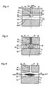
- Fig. 5 is a vertical sectional view typically showing fluid flow in the fluid jet in the first example
- Fig. 6 is a vertical sectional view typical entanglement of yarn in the first example.
- the flow of the fluid jet 5 is controlled by the straight passage Sp in the jet direction, and since the expanding passage Ep is downstream of the straight passage Sp, the fluid flow expands in a direction parallel to the reference line APYp (Fig. 4) (the second axial line AYp) in the area near the fluid outlet Of. So, in the space near the wall surface of the yarn passage Yp facing the fluid outlet Of, a high pressure portion 7 (Fig. 5) is formed, and in the space near the wall surface of the yarn passage Yp near the fluid outlet Of, low pressure portions 8a and 8b (Fig. 5) are formed.
- the maximum width WtOf (Figs. 2 and 3) of the fluid outlet Of (the end of the expanding passage Ep) of the fluid passage Fp in the direction perpendicular to the reference plane BP is substantially equal to the maximun width WtYp (Figs. 2 and 3) of the yarn passage Yp.
- the reference line ApYp agrees with the second axial line AYp.
- the configuration of the fluid passage Fp in a plane vertical to the reference plane BP and parallel to the direction of the reference line APYp (the second axial line AYp) is rectangular
- the configuration of the yarn passage Yp in a plane perpendicular to the reference plane BP and perpendicular to the direction of the reference line APYp (the second axial line AYp) is rectangular.
- Fig. 7 is a vertical sectional view showing a second example of the apparatus of the present invention.
- the second example shows an apparatus 9 for fluid treatment of yarn formed with a nozzle block NB in which a top front piece 10a and a top rear piece 10b are provided with a straight portion, i.e., tapered portion as the face forming the expanding passage Ep, instead of a curve as in the first example.
- the other portions of the second example are the same as those of the first example.
- the second example assures a similar action as that of the first example.
- the second, example is easier to manufacture regarding the expanding passage Ep portion, and is higher in manufacturing accuracy and somewhat less costly comparing with the first example.
- Fig. 8 is a perspective view showing a third example of the apparatus of the present invention.
- the third example shows an apparatus 11 for fluid treatment of yarn formed with a nozzle block NB in which the right-hand piece 2a of the first example is divided into top and bottom right pieces 12a, 12b with a clearance kept between them for easier yarn threading into the yarn passage Yp of the first example.
- the clearance between the top right piece 12a and the bottom right piece 12b forms a yarn threading slit 13.
- the yarn threading slit 13 is often used in the conventional entangling nozzles.
- the other portions of the third example are the same as those of the first example.
- Fig. 9 is a perspective view showing a fourth example of the apparatus of the present invention.
- Fig. 10 is a vertical sectional view of the fourth example, showing typical entanglement of the yarn.
- Fig. 11 is a cross-sectional view of the fourth example.
- the nozzle block NB of an apparatus 14 for fluid treatment of yarn comprises two pieces. On a base piece 15, a nozzle piece 16 is attached. The base piece 15 and the nozzle piece 16 are coupled by any proper coupling means (not illustrated). In the bottom face of the nozzle piece 16, a groove 17 having semi-circular cross section is formed. When the nozzle piece 16 is overlaid on the base piece 15, the groove 17 forms the yarn passage Yp.
- the nozzle piece 16 has the fluid passage Fp formed in it. The fluid inlet If of the fluid passage Fp is opened at the top of the nozzle piece 16 and the fluid outlet Of is opened in the top wall surface of the yarn passage Yp.
- the fluid passage Fp has the straight passage Sp with a desired length and the expanding passage Ep ranging from the end of the straight passage Sp to the fluid outlet Of, as in the first example.
- the expanding passage Ep in the fourth example gradually expands in the entire circumference from the end of the straight passage Sp, and the wall surface of the expanding passage Ep in the direction of the axial line ASp of the straight passage Sp forms a smooth curve.
- the fluid jet supplied into the fluid passage Fp passes through the straight passage Sp and is injected from the expanding passage Ep into the yarn passage Yp.
- the injected jet entangles the filaments constituting the yarn 6 running in the yarn passage Yp.
- the number of pieces constituting the nozzle block NB can be two and that the expanding passage Ep formed by machining the wall surface of the groove 17 can be easily machined, to assure good manufacturing accuracy in the formation of the expanding passage Ep.
- Fig. 12 is a cross-sectional view showing a fifth example of the apparatus of the present invention.
- the nozzle block NB of an apparatus 18 for fluid treatment of yarn in the fifth example has two fluid passages Fp, and in this regard, it is different from that of the fourth example.
- the other portions are the same as those of the fourth example. It has been conventionally practiced to use two or three fluid passages Fp to the yarn passage Yp.
- the fifth example has the technique of the present invention applied to the two fluid passages Fp1 and Fp2, and in this regard, it is different from the conventional entangling nozzles. That is, the fluid passage Fp1 has a straight passage Sp1 and an expanding passage Ep1, and the fluid passage Fp2 also has a straight passage Sp2 and an expanding passage Ep2.
- the actions of the respective passages are substantially the same as in the first example.
- Fig. 13 is a cross-sectional view showing a sixth example of the apparatus of the present invention.
- the fluid treating device 19 for a yarn of a sixth example is formed by a nozzle block NB with still another fluid passage Fp3 formed in addition to those in the fifth example.
- the fluid passage Fp3 is formed in the base piece 15 and injects a fluid jet from below to oppose the fluid jets injected from the downwardly directed fluid passages Fp1 and Fp2.
- Such an entangling nozzle with three fluid passages is conventionally known.
- the fluid passage Fp3 also has a straight passage Sp3 and an expanding passage Ep3 unlike the conventional entangling nozzle.
- a reference plane BP3 exists for the straight passage Sp3, high pressure areas and low pressure areas as explained (of the kind illustrated in Fig. 5) are formed.
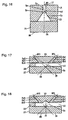
- Fig. 14 is a cross-sectional view showing a seventh example of the apparatus of the present invention.
- the seventh example is an apparatus 20 for fluid treatment of yarn formed by a nozzle block NB with a yarn passage Yp having circular cross section, instead of the yarn passage Yp having semi-circular cross section in the fourth example.
- a groove 21 identical in form and size with the groove 17 formed in the nozzle piece 16 is formed in the top surface of the base piece 15.
- the other portions of the seventh example are the same as those of the fourth example.
- Fig. 15 is a cross-sectional view showing an eighth example of the apparatus of the present invention.
- the eighth example is an apparatus 22 for fluid treatment of yarn formed by a nozzle block NB with a yarn passage Yp having a truncated circular cross section formation, intermediate between the semi-circular form adopted in the fourth example and the circular form adopted in the seventh example.
- a nozzle block NB with a yarn passage Yp having a truncated circular cross section formation, intermediate between the semi-circular form adopted in the fourth example and the circular form adopted in the seventh example.
- an imperfectly circular groove 23 is formed in the bottom surface of the nozzle piece 16.
- the other portions of the eighth example are the same as those of the fourth example.
- Fig. 16 is a cross-sectional view showing a ninth example of the apparatus of the present invention.
- the ninth example is an apparatus 24 for fluid treatment of yarn formed with a nozzle block NB with a yarn passage Yp having a triangular cross section, instead of the yarn passage having a semicircular cross section adopted in the fourth example.
- a triangular groove 25 is formed in the bottom face of the nozzle piece 16.
- the other portions of the ninth example are the same as those of the fourth example.
- Fig. 17 is a cross-sectional view showing a tenth example of the apparatus of the present invention.
- the fluid treating device 26 for a yarn of the tenth example is formed by a nozzle block NB comprising a base piece 27, an intermediate piece 28 and a nozzle piece 29. Secured on the base piece 27, the intermediate piece 28 is placed, and on the intermediate piece 28, the nozzle piece 29 is placed. These three pieces are coupled by any proper coupling means (not illustrated).
- the space surrounded by the top surface of the base piece 27, the right-hand side face of the intermediate piece 28 and the bottom surface of the nozzle piece 29 and extending in the longitudinal direction of the nozzle block NB is the yarn passage Yp.
- the right-hand side of the yarn passage Yp is opened in the outer surface of the nozzle block NB.
- the opening is a yarn threading slit 13.
- the nozzle piece 29 has a fluid passage Fp1 and a fluid passage Fp2 formed in it.
- the fluid passage Fp1 has a straight passage Sp1 and an expanding passage Ep1
- the fluid passage Fp2 also has a straight passage Sp2 and an expanding passage Ep2.
- a reference plane BP1 exists, and for the straight passage Sp2, a reference plane BP2 exists.
- the respective actions of the straight passage Sp1, the expanding passage Ep1, the straight passage Sp2 and the expanding passage Ep2 are substantially the same as in the first example.
- Fig. 18 is a cross-sectional view showing an eleventh example of the apparatus of the present invention.
- the eleventh example is an apparatus 30 for fluid treatment of yarn formed by a nozzle block NB with a yarn passage Yp modified in the cross sectional form adopted in the tenth example.
- a groove 31 having a triangular cross section is formed in the bottom surface of the nozzle piece 29 at an intermediate position between the fluid passages Fp1 and Fp2.
- the other portions of the eleventh example are the same as those of the tenth example.
- the actions of the straight passage Sp1, the expanding passage Ep1, the straight passage Sp2 and the expanding passage Ep2 are substantially the same as those in the first example.
- Fig. 19 is a perspective view showing a twelfth example of the apparatus of the present invention.
- Fig. 20 is a vertical sectional view showing the twelfth example, where typical entanglement of the yarn is also shown.
- the fluid treating device 32 for a yarn is formed by a nozzle block NB comprising four pieces.
- a front piece 33 and a rear piece 34 are positioned with a space kept between them.
- An intermediate right piece 35a and an intermediate left piece 35b are secured between the front piece 33 and the rear piece 34.
- the intermediate right piece 35a and the intermediate left piece 35b are positioned with a space kept between them.
- the yarn passage Yp of the nozzle block NB is formed as a space surrounded by the four pieces.
- the nozzle block NB has two fluid passages formed in it.
- One fluid passage Fp1 is formed in the intermediate right piece 35a, and its fluid opening Of1 is positioned in the wall surface of the yarn passage Yp.
- the fluid passage Fp1 extends in the rear piece 34 (not illustrated), and in the rear surface thereof, the fluid inlet If1 of the fluid passage Fp1 is formed.
- the other fluid passage Fp2 is formed in the intermediate left piece 35b, and its fluid outlet Of2 is positioned in the wall surface of the yarn passage Yp.
- the fluid passage Fp2 extends in the rear piece 34 (not illustrated), and in the rear surface thereof, the fluid inlet If2 of the fluid passage Fp2 is formed.
- the fluid passage Fp1 has a straight passage Sp1 and an expanding passage Ep1 in succession.
- the fluid passage Fp2 has a straight passage Sp2 and an expanding passage Ep2 in succession.
- the yarn running in the yarn passage Yp receives entanglement treatment of entanglement by the fluid jets injected from the fluid passages Fp1 and Fp2.
- the actions of the straight passage Sp1, the expanding passage Ep1, the straight passage Sp2 and the expanding passage Ep2 are substantially the same as those described in the first example.
- Fig. 21 is a vertical sectional view showing a thirteenth example of the apparatus of the present invention.
- the thirteenth example is an apparatus 37 for fluid treatment of yarn formed by a nozzle block NB with an expanding outlet 36 expanding in the entire circumference at the yarn outlet Oy of the yarn passage Yp in the twelfth example.
- the other portions of the thirteenth example are the same as those in the twelfth example.
- the expanding outlet 36 of the fluid treating device 37 acts to promote the discharge of the fluid jets used for entangling the filaments, from the yarn outlet Oy of the yarn passage Yp.
- the yarn inlet Iy portion of the yarn passage Yp may be expanding, or both the yarn outlet Oy portion and the yarn inlet Iy portion may be expanding.
- the fluid passages Fp1 and Fp2 are formed obliquely toward the yarn outlet Oy, it is preferable that the yarn outlet Oy portion expands.
- the expansion of the yarn passage Yp at the yarn inlet Iy portion and/or the yarn outlet Oy portion is effective to achieve bulky entanglement of the filaments.
- Fig. 22 is a vertical sectional view showing a fourteenth example of the apparatus of the present invention.
- the fourteenth example is an apparatus 39 for fluid treatment of yarn formed by a nozzle block NB with an expanding outlet 38 expanding only in half the circumference instead of expanding in the entire circumference at the yarn outlet Oy portion of the yarn passage Yp in the thirteenth example.
- the expanding outlet 38 expanding only in half the circumference also acts to promote the discharge of the fluid jets from the yarn outlet Oy as in the thirteenth example, and acts to make the filaments of the yarn entangled bulkily.
- Fig. 23 is a perspective view showing a fifteenth example of the apparatus of the present invention.
- Fig. 24 is a vertical sectional view of the fifteenth example.
- the nozzle block NB of the fluid treating device 40 for a yarn in the fifteenth example comprises two pieces; a base piece 41 and a nozzle piece 42 secured thereto. The entire shape is cylindrical.
- a groove 43 having a semi-circular cross section is formed in the flat surface of the nozzle piece 42.
- a groove 44 having a semi-circular cross section is formed in the flat surface of the nozzle piece 42.
- the base piece 41 and the nozzle piece 42 are coupled by any proper coupling means (not illustrated).
- the grooves 43 and 44 facing each other form a yarn passage Yp having a circular configuration in cross section.
- the nozzle piece 42 has a fluid passage Fp formed in it.
- the fluid inlet If of the fluid passage Fp is formed in the curved outer surface of the nozzle piece 42, and the fluid outlet Of is formed in the wall surface of the yarn passage Yp.
- the yarn outlet Of portion of the yarn passage Yp is formed as an expanding outlet 45 expanding in the entire circumference.
- the fluid passage Fp has a straight passage Sp and an expanding passage Ep in succession.
- Fig. 25 is a vertical sectional view showing a sixteenth example of the apparatus of the present invention.
- the sixteenth example is an apparatus 47 for fluid treatment of yarn formed by a nozzle block NB with an expanding outlet 46 expanding only in half the circumference at the yarn outlet Oy portion of the yarn passage Yp, as distinguished from that the yarn outlet Oy portion of the yarn passage Yp in the fifteenth example has the expanding outlet 45 expanding in the entire circumference.
- the expanding outlet 46 is formed on the side where the fluid passage Fp is positioned.
- the other portions of the sixteenth example are the same as those of the fifteenth example.
- Fig. 26 is a vertical sectional view showing a seventeenth example of the apparatus of the present invention.
- the seventeenth example is an apparatus 49 for fluid treatment of yarn formed by a nozzle block NB in which the expanding outlet 48 at the yarn outlet Oy portion of the yarn passage Yp is formed on the side opposite to the position of the expanding outlet 46 of the sixteenth example, i.e., on the side opposite to the side where the fluid passage Fp is positioned.
- the positional relation between the expanding outlet at the yarn outlet Oy portion and the fluid passage Fp is selected based on the intended filament entanglement of the entangled yarn to be produced and used.
- Fig. 27 is a vertical sectional view showing a conventional apparatus 50 for fluid treatment of yarn.
- the nozzle block NB of the conventional apparatus comprises five pieces like the nozzle block NB of the apparatus 1 in the first example.
- a right piece 51a (not illustrated) and a left piece 51b are positioned with a predetermined space kept between them.
- a bottom piece 52, a top front piece 53a and a top rear piece 53b are positioned between the right and left pieces 51a (not illustrated) and 51b.
- the bottom piece 52 and the top front and top rear pieces 53a and 53b are positioned with a space kept between them.
- the top front piece 53a and the top rear piece 53b are positioned with a space kept between them.
- the yarn passage Yp is formed as a space surrounded by the surfaces of the right and left pieces 51a (not illustrated) and 52a, the bottom piece 52 and the top front and top rear pieces 53a and 53b.
- One of the front and rear openings of the yarn passage Yp in the outer surface of the nozzle blockNB is the yarn inlet Iy and the other is the yarn outlet Oy.
- the fluid passage Fp is formed as a space surrounded by the surfaces of the right and left pieces 51a (not illustrated) and 51b and the top front and top rear pieces 53a and 53b.
- the opening of the fluid passage Fp in the outer surface of the nozzle block NB is the fluid inlet If of the fluid passage Fp, and the opening of the fluid passage Fp in the inner wall surface of the yarn passage Yp is the fluid outlet Of of the fluid passage Fp.
- a large difference between the conventional apparatus 50 and the apparatus 1 in the first example is that the fluid outlet Of portion of the fluid passage Fp of the conventional apparatus 50 is opened as it is, in the inner wall surface of the yarn passage Yp without expanding in the direction parallel to the axial line of the yarn passage Yp. So, the conventional apparatus 50 for fluid treatment of yarn does not have the action provided by the expanding passage Ep in succession to the straight passage Sp described in connection with the first example.
- the fluid outlet Of of the fluid passage Fp may be chamfered at the circumference of the end, to prevent the breaking of filaments of the yarn due to possible contact with the surface of fluid outlet Of while the yarn is being entangled.
- any such chamfering is radically different in purpose and action from the expanding passage Ep in accordance with the present invention.
- a polyester yarn of 50 deniers having 18 filaments was used.
- the device of the first example (Figs. 1 through 6) was used.
- the fluid jet used was compressed air with a pressure of 0.5 MPa and a flow rate of 130 l/min (standard state).
- the tension of the yarn supplied into the yarn passage Yp was 20 g.
- the length Ls of the straight passage Sp was 7.3 mm, and the width Wasp was 0.9 mn.
- the length Le of the expanding passage Ep was 5.7 mm, and the width WaOf of the expanding passage Ep at the fluid outlet Of was 2.5 mm.
- the value of T was 8° .
- the vertical width of the yarn passage Yp was 2 mm and the horizontal width WtYp was 2 mm.
- the curve formed by the wall surface of the expanding passage Ep in the reference plane BP was 20 mn in the radius of curvature.
- the entangling degree of the entangled yarn obtained was 17.8 (pieces/m).
- the entangling degree was measured by using an entanglement tester (R-2050 produced by Rosshield) according to the method stated in JIS 1013, and the average value of 50 measurements was adopted.
- the device of the second example (Fig. 7) was used for entangling a yarn under the following conditions.
- T was 11° .
- the other conditions were the same as in Example 1.
- the entangling degree of the entangled yarn obtained was 15.3 (piece/m).
- the entangling degree of the entangled yarn obtained was 8.3 (piece/m).
- a yarn was entangled as described in Example 1, except that the width WaOf of the expanding passage Ep was 1.7 mm, to keep the value of T at 4° , and that the curve formed by the wall surface of the expanding passage Ep in the reference plane BP was 50 mm in the radius of curvature.
- the entangling degree of the entangled yarn obtained was 1.60 (piece/m).
- a yarn was entangled as described in Example 1, except that the width WaOf of the expanding passage Ep was 2.1 mm, to keep the value of T at 6° , and that the curve formed by the wall surface of the expanding passage Ep in the reference plane BP was 30 mn in the radius of curvature.
- the entangling degree of the entangled yarn obtained was 13.9 (pieces/m).
- a yarn was entangled as described in Example 1, except that the width WaOf of the expanding passage Ep was 4.5 mm, to keep the value of T at 18° , and that the curve formed by the wall surface of the expanding passage Ep in the reference plane BP was 10 nm in the radius of curvature.
- the entangling degree of the entangled yarn obtained was 17.8 (pieces/m).
- a yarn was entangled as described in Example 1, except that the width WaOf of the expanding passage Ep was 8.9 mm, to keep the value of T at 35° , and that the curve formed by the wall surface of the expanding passage Ep in the reference plane BP was 5 nm in the radius of curvature.
- the entangling degree of the entangled yarn obtained was 11.8 (piece/m). In Example 6, since the value of T exceeded 20° C, the entangling degree was lower than that in Example 1.
Landscapes
- Engineering & Computer Science (AREA)
- Physics & Mathematics (AREA)
- Fluid Mechanics (AREA)
- Textile Engineering (AREA)
- Mechanical Engineering (AREA)
- Yarns And Mechanical Finishing Of Yarns Or Ropes (AREA)
Description
Claims (4)
- An apparatus for fluid treatment of yarn comprising a nozzle block (NB), a yarn passage (Yp) formed in said nozzle block (NB) and having a yarn inlet (Iy) and a yarn outlet (Oy) in said the nozzle block (NB), and a fluid passage (Fp) formed in said nozzle block (NB) and having a fluid inlet (If) in the outer surface of said nozzle block (NB) and a fluid outlet (Of) in an inner wall surface of said yarn passage (Yp), characterized in that:(i) said fluid passage (Fp) comprises a substantially straight passage (Sp) and an a expanding passage (Ep) communicated with said yarn passage (Yp),(ii) said substantially straight passage (Sp) in which a first distance (LSp) is substantially constant throughout a range along said fluid passage (Fp), where said first distance (LSp) is k distance in the direction of a first perpendicular (AtFp) from a first axial line (AFp) to a wall surface of said fluid passage (Fp); said first perpendicu-lar (AtFp) is a line perpendicular to said first axial line (AFp); and said first axial line (AFp) is the axial line of said fluid passage (Fp), and(iii) an expanding passage (Ep) in which a second distance (LEp) is gradually increased from the end of said substantially straight passage (Sp) to said fluid outlet (Of) at least in either the direction of said yarn inlet (1y) or the direction of said yarn outlet (Oy), where said second distance (LEp) is a distance in the direction of a second perpendicular (AtBP) from said first axial line (AFp) to the wall surface of said fluid passage (Fp); said second perpendicular (AtBP) is a line perpendicular to said first axial line (AFp) in a reference plane (BP); said reference plane (BP) is a plane containing said first axial line (AFp) and a reference line (APYp); said reference line (APYp) is a the parallel to a second axial line (AYp); and said second axial line (AYp) is the axial line of said yarn passage (Yp), and(iv) the maximum width of said fluid outlet in the direction perpendicular to said reference plane (BP) is substantially equal to the maximum width of said yarn passage (Yp) in the same direction.
- An apparatus for fluid treatment of yarn according to claim 1, wherein said reference line (APYp) agrees with said second axial line (Ayp).
- An apparatus for fluid treatment of yarn according to claim 2, wherein the form of the cross section of said fluid passage (Fp) in a plane perpendicular to said reference plane (BP) and parallel to the direction of said reference line (APYp) is substantially rectangular, and wherein the form of the cross section of said yarn passage (Yp) in a plane perpendicular to said reference plane (BP) and perpendicular to the direction of said reference line (APYp) is substantially rectangular.
- An apparatus for fluid treatment of yarn according to claim 1, wherein the cross-sectional area of said yarn passage (Yp) in a plane perpendicular to said second axial line (AYp) expands at least at either of the yarn inlet portion containing said yarn inlet (Iy) or the yarn outlet portion containing said yarn outlet (Oy).
Priority Applications (1)
| Application Number | Priority Date | Filing Date | Title |
|---|---|---|---|
| DE69815405T DE69815405T2 (en) | 1998-03-30 | 1998-03-30 | Device for treating a yarn with a liquid and intermingled multifilament yarn |
Applications Claiming Priority (1)
| Application Number | Priority Date | Filing Date | Title |
|---|---|---|---|
| EP98105806A EP0947619B1 (en) | 1998-03-27 | 1998-03-30 | Apparatus for fluid treatment of yarn and a yarn composed of entangled multifilament |
Related Parent Applications (2)
| Application Number | Title | Priority Date | Filing Date |
|---|---|---|---|
| EP98105806.8 Division | 1998-03-30 | ||
| EP98105806A Division EP0947619B1 (en) | 1998-03-27 | 1998-03-30 | Apparatus for fluid treatment of yarn and a yarn composed of entangled multifilament |
Publications (2)
| Publication Number | Publication Date |
|---|---|
| EP1207226A1 EP1207226A1 (en) | 2002-05-22 |
| EP1207226B1 true EP1207226B1 (en) | 2003-06-04 |
Family
ID=8231686
Family Applications (1)
| Application Number | Title | Priority Date | Filing Date |
|---|---|---|---|
| EP01131058A Expired - Lifetime EP1207226B1 (en) | 1998-03-30 | 1998-03-30 | Apparatus for fluid treatment of yarn and a yarn composed of entangled multifilament |
Country Status (2)
| Country | Link |
|---|---|
| EP (1) | EP1207226B1 (en) |
| DE (1) | DE69811853T2 (en) |
Families Citing this family (2)
| Publication number | Priority date | Publication date | Assignee | Title |
|---|---|---|---|---|
| ITBI20040004A1 (en) | 2004-10-12 | 2005-01-12 | Sinterama S P A | High performance device for the air interlacing of a wire, and relative method |
| US7406818B2 (en) | 2004-11-10 | 2008-08-05 | Columbia Insurance Company | Yarn manufacturing apparatus and method |
Family Cites Families (8)
| Publication number | Priority date | Publication date | Assignee | Title |
|---|---|---|---|---|
| FR2094341A5 (en) * | 1970-06-18 | 1972-02-04 | Rhodiaceta | |
| US3750242A (en) * | 1971-06-30 | 1973-08-07 | Celanese Corp | Yarn compacting apparatus |
| JPS5212362A (en) * | 1975-07-18 | 1977-01-29 | Toray Industries | Fluid treatment apparatus |
| US4251904A (en) * | 1978-11-08 | 1981-02-24 | Toray Industries, Inc. | Yarn treating apparatus |
| US4535516A (en) * | 1980-08-18 | 1985-08-20 | Maschinenfabrik Rieter Ag | Apparatus for the production of fixed point multifilament yarns |
| EP0121010B1 (en) * | 1983-03-30 | 1986-12-10 | Toray Industries, Inc. | Apparatus for interlacing multifilament yarn |
| CH681633A5 (en) * | 1990-07-02 | 1993-04-30 | Heberlein & Co Ag | |
| TW224495B (en) * | 1992-11-02 | 1994-06-01 | Toray Industries |
-
1998
- 1998-03-30 DE DE1998611853 patent/DE69811853T2/en not_active Expired - Fee Related
- 1998-03-30 EP EP01131058A patent/EP1207226B1/en not_active Expired - Lifetime
Also Published As
| Publication number | Publication date |
|---|---|
| EP1207226A1 (en) | 2002-05-22 |
| DE69811853T2 (en) | 2003-11-13 |
| DE69811853D1 (en) | 2003-04-10 |
Similar Documents
| Publication | Publication Date | Title |
|---|---|---|
| EP0947619B1 (en) | Apparatus for fluid treatment of yarn and a yarn composed of entangled multifilament | |
| JP3433946B2 (en) | Aerodynamic texturing method, textured nozzle, nozzle head and use thereof | |
| US7353575B2 (en) | Method and device for producing a fancy knotted yarn | |
| US4535516A (en) | Apparatus for the production of fixed point multifilament yarns | |
| EP1207226B1 (en) | Apparatus for fluid treatment of yarn and a yarn composed of entangled multifilament | |
| US5325572A (en) | Yarn treating jet | |
| US3259952A (en) | Jet device for blowing yarn and process | |
| JPH0247330A (en) | Apparatus for entangling fiber | |
| US6308388B1 (en) | Texturing jet | |
| JPS6022093B2 (en) | Jet for texturing | |
| JP2911584B2 (en) | Splicing equipment | |
| JP2023537099A (en) | Interlacing nozzle for producing knotted yarn and method for interlacing yarn | |
| JP5229117B2 (en) | Multi-filament yarn entanglement imparting device and entanglement imparting method | |
| JPH11256445A (en) | Fluid treating apparatus for yarn and yarn comprising entangled filament | |
| US6370746B1 (en) | Yarn treatment jet | |
| JPH09250043A (en) | Apparatus for treating many yarns with fluid | |
| KR19990075506A (en) | Yarns consisting of a fluid handling device and tangled filaments | |
| JP2645473B2 (en) | Yarn processing nozzle | |
| JPH05222640A (en) | Yarn interlacer | |
| JP3158709B2 (en) | Nozzle for entanglement of yarn | |
| JPS6183341A (en) | Fluid jet treatment apparatus | |
| JPH0892839A (en) | Interlacing nozzle | |
| JPH03227420A (en) | Fancy yarn and processing nozzle therefor | |
| JP2016172938A (en) | Interlacing device for yarn and manufacturing method for synthetic fiber using the same | |
| JP2000273735A (en) | Fluid treating apparatus |
Legal Events
| Date | Code | Title | Description |
|---|---|---|---|
| PUAI | Public reference made under article 153(3) epc to a published international application that has entered the european phase |
Free format text: ORIGINAL CODE: 0009012 |
|
| 17P | Request for examination filed |
Effective date: 20011221 |
|
| AC | Divisional application: reference to earlier application |
Ref document number: 947619 Country of ref document: EP |
|
| RIN1 | Information on inventor provided before grant (corrected) |
Inventor name: SHIMADA, KOUJI Inventor name: SANO, TAKAO Inventor name: SAIJO, TERUAKI |
|
| GRAH | Despatch of communication of intention to grant a patent |
Free format text: ORIGINAL CODE: EPIDOS IGRA |
|
| GRAH | Despatch of communication of intention to grant a patent |
Free format text: ORIGINAL CODE: EPIDOS IGRA |
|
| AKX | Designation fees paid |
Designated state(s): CH DE FR GB IT LI |
|
| GRAA | (expected) grant |
Free format text: ORIGINAL CODE: 0009210 |
|
| AC | Divisional application: reference to earlier application |
Ref document number: 0947619 Country of ref document: EP Kind code of ref document: P |
|
| AK | Designated contracting states |
Designated state(s): CH DE FR GB IT LI |
|
| PG25 | Lapsed in a contracting state [announced via postgrant information from national office to epo] |
Ref country code: FR Free format text: LAPSE BECAUSE OF FAILURE TO SUBMIT A TRANSLATION OF THE DESCRIPTION OR TO PAY THE FEE WITHIN THE PRESCRIBED TIME-LIMIT Effective date: 20030604 |
|
| REG | Reference to a national code |
Ref country code: GB Ref legal event code: FG4D |
|
| REG | Reference to a national code |
Ref country code: CH Ref legal event code: EP |
|
| REF | Corresponds to: |
Ref document number: 69815405 Country of ref document: DE Date of ref document: 20030710 Kind code of ref document: P |
|
| REG | Reference to a national code |
Ref country code: CH Ref legal event code: NV Representative=s name: PATENTANWAELTE BREITER + WIEDMER AG |
|
| PLBE | No opposition filed within time limit |
Free format text: ORIGINAL CODE: 0009261 |
|
| STAA | Information on the status of an ep patent application or granted ep patent |
Free format text: STATUS: NO OPPOSITION FILED WITHIN TIME LIMIT |
|
| 26N | No opposition filed |
Effective date: 20040305 |
|
| EN | Fr: translation not filed | ||
| PG25 | Lapsed in a contracting state [announced via postgrant information from national office to epo] |
Ref country code: IT Free format text: LAPSE BECAUSE OF NON-PAYMENT OF DUE FEES Effective date: 20050330 |
|
| PGFP | Annual fee paid to national office [announced via postgrant information from national office to epo] |
Ref country code: GB Payment date: 20050330 Year of fee payment: 8 |
|
| PG25 | Lapsed in a contracting state [announced via postgrant information from national office to epo] |
Ref country code: GB Free format text: LAPSE BECAUSE OF NON-PAYMENT OF DUE FEES Effective date: 20060330 |
|
| GBPC | Gb: european patent ceased through non-payment of renewal fee |
Effective date: 20060330 |
|
| PGFP | Annual fee paid to national office [announced via postgrant information from national office to epo] |
Ref country code: DE Payment date: 20070322 Year of fee payment: 10 |
|
| PGFP | Annual fee paid to national office [announced via postgrant information from national office to epo] |
Ref country code: CH Payment date: 20070328 Year of fee payment: 10 |
|
| REG | Reference to a national code |
Ref country code: CH Ref legal event code: PFA Owner name: TORAY INDUSTRIES, INC. Free format text: TORAY INDUSTRIES, INC.#2-1, NIHONBASHI MUROMACHI 2-CHOME, CHUO-KU#TOKYO 103-8666 (JP) -TRANSFER TO- TORAY INDUSTRIES, INC.#2-1, NIHONBASHI MUROMACHI 2-CHOME, CHUO-KU#TOKYO 103-8666 (JP) |
|
| REG | Reference to a national code |
Ref country code: CH Ref legal event code: PL |
|
| PG25 | Lapsed in a contracting state [announced via postgrant information from national office to epo] |
Ref country code: LI Free format text: LAPSE BECAUSE OF NON-PAYMENT OF DUE FEES Effective date: 20080331 Ref country code: DE Free format text: LAPSE BECAUSE OF NON-PAYMENT OF DUE FEES Effective date: 20081001 Ref country code: CH Free format text: LAPSE BECAUSE OF NON-PAYMENT OF DUE FEES Effective date: 20080331 |