EP1798663A2 - Optische Festkamera-Leseeinrichtung und Verfahren zur Installation und Ausrichtungsdiagnose - Google Patents
Optische Festkamera-Leseeinrichtung und Verfahren zur Installation und Ausrichtungsdiagnose Download PDFInfo
- Publication number
- EP1798663A2 EP1798663A2 EP06026253A EP06026253A EP1798663A2 EP 1798663 A2 EP1798663 A2 EP 1798663A2 EP 06026253 A EP06026253 A EP 06026253A EP 06026253 A EP06026253 A EP 06026253A EP 1798663 A2 EP1798663 A2 EP 1798663A2
- Authority
- EP
- European Patent Office
- Prior art keywords
- camera
- aiming
- supporting plane
- luminous
- equipment
- Prior art date
- Legal status (The legal status is an assumption and is not a legal conclusion. Google has not performed a legal analysis and makes no representation as to the accuracy of the status listed.)
- Withdrawn
Links
Images


Classifications
-
- G—PHYSICS
- G06—COMPUTING; CALCULATING OR COUNTING
- G06K—GRAPHICAL DATA READING; PRESENTATION OF DATA; RECORD CARRIERS; HANDLING RECORD CARRIERS
- G06K7/00—Methods or arrangements for sensing record carriers, e.g. for reading patterns
- G06K7/10—Methods or arrangements for sensing record carriers, e.g. for reading patterns by electromagnetic radiation, e.g. optical sensing; by corpuscular radiation
- G06K7/10544—Methods or arrangements for sensing record carriers, e.g. for reading patterns by electromagnetic radiation, e.g. optical sensing; by corpuscular radiation by scanning of the records by radiation in the optical part of the electromagnetic spectrum
- G06K7/10712—Fixed beam scanning
- G06K7/10722—Photodetector array or CCD scanning
Definitions
- the present invention relates to a fixed optical reading equipment of the camera type and to methods for its installation and for the diagnostic of its alignment.
- optical reading equipment is used to indicate an equipment able to acquire optical information associated to an object placed on a supporting plane (for example, distance, volume, encumbrance, or data identifying it, particularly an optical code associated to the object) through the acquisition and the processing of an acquisition zone on the supporting plane.
- acquisition zone on the supporting plane it is meant that the view cone of the camera is directed toward at least a portion of the supporting plane, the field of view being focused at a proper distance.
- optical information is used to indicate any graphical representation having the function of storing a coded or non-coded information.
- a particular example of optical information is comprised of linear or two-dimensional optical codes, wherein the information is coded trough suitable combinations of elements having a predetermined, for example squared, rectangular or hexagonal shape, of a dark color (normally black) separated by light elements (spaces, normally white), such as bar codes, stacked codes and two-dimensional codes in general, color codes, etc.
- optical information further comprises, more in general, other graphical shapes as well, including printed characters (letters,_ numbers, etc.) and particular shapes ("patterns") (such as, for example stamps, devices, signatures, fingerprints etc.).
- patterns such as, for example stamps, devices, signatures, fingerprints etc.
- optical information further comprises graphical representations that may be detected, not only in the visible light range, but also in the range of wavelengths comprised between infrared and ultraviolet.
- fixed optical reading equipment is used to indicate such an optical reading equipment for use without human activation ("unattended scanner"), particularly at a conveyor belt (or other moving means) on which articles to be detected move, and also at a station where an operator manually inputs the articles to be detected.
- the article detection may comprise reading an optical code and/or measuring a distance and/or a volume, etceteras.
- the invention relates to such a fixed optical reading equipment of the type comprising a camera having a one-dimensional (linear) or two-dimensional (matrix) array of photosensors, particularly of the CCD or C-MOS type.
- optical reading equipment of the camera type linear or matrix, particularly CCD or C-MOS
- CCD linear or matrix
- C-MOS three-dimensional codes or characters
- this equipment is comprised of at least one properly-said camera and a lamp or solid state illumination system.
- a lamp or solid state illumination system In most of the real installations, there are also one or more deflecting mirrors. As will be clearer hereinafter, these components may be housed in a common container or in separate containers.
- the camera has the function of collecting the image wherein the information has to be extracted (the whole image itself, or an optical code -as above defined- contained therein) through a proper optical system and dedicated opto-electronics and electronics, wherein an optical sensor comprised of a linear or matrix CCD or C-MOS type exists.
- the image is collected through storing successive scans, each of which represents a very thin "line" of the whole image.
- the movement of the supporting plane, or of the object at the fixed reading station, allows successive lines to be accumulated, and therefore the whole image to be created.
- the illumination system allows the acquisition zone to be illuminated with the proper light levels and illumination angles.
- the deflecting mirror (or the deflecting mirrors) allows the installation of the reading equipment to be optimized from the point of view of the space taken up with respect to the conveyor belt, and therefore to direct the camera field of view in the desired area.
- depth of field is used to indicate the range of camera-to-object distances, around the working distance each time set, within which the object is sufficiently focused to allow reading the optical information.
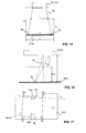
- a slight error in the installation angle of the camera 100 with respect to the supporting plane 102 may lead to errors in the optical path comparable with, or greater than, the depth of field DOF.
- the result is that the image may be focused in a first region 103 of the supporting plane 102, but out of focus in a second region 104 of the supporting plane 102, and therefore, as a whole, it will have a low quality, which makes it difficult to recognize the optical symbols or the characters.
- axis X represents the transversal direction of the supporting plane 102
- axis Z represents the vertical direction
- axis Y (not shown in Fig. 1) represents the longitudinal direction of the supporting plane 102.
- axis Y further represents its moving direction.
- FIG. 2 it is shown how the focused surface of the camera driven by the autofocus system should be (Fig. 2) and how it is, on the contrary, in case of a position error with respect to a height sensor associated with the supporting plane 102 and providing to camera 100, in a manner known per se, a signal indicating the height of an object passing by the camera (Fig. 3).
- Line 105 represents the outline of an object, for example a parcel moving in the direction indicated by the arrow on the supporting plane 102
- line 106 represents the focused surface of camera 100.
- the camera is at a correct distance 107 from the height sensor (not shown, but operating along the height measurement line 112). In such a case the lines 105 and 106 overlap and therefore the image quality is optimum.
- the camera 100 focuses the object 105 late and, therefore, it is out of focus. Similar problems arise if the camera 100 is not correctly positioned with respect to a presence sensor (not shown).
- the light needs to be as intense and uniform as possible on the whole acquisition zone (scan line in case of a linear camera) and at any height. This problem is even more exaggerated in solid state illumination systems with respect to the lamp ones, in that the former create, by their own nature, a light blade that is particularly thin, and therefore difficult to be centered with respect to the scan line.
- the acquisition distance of a camera of the type here of concern is rather long (the useful field of view may be placed at a distance of two to three meters from the camera). Such a distance is required for the field of view of the sensor of camera 100 to be able to cover the whole cross extent of the supporting plane 102 at any working distance, that is independently of the height of the articles. To install the camera directly over the supporting plane would require the presence of spaces that are not available (2-3 meters above the conveyor belt mean 3-5 meters above the floor).
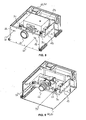
- deflecting mirrors allows differently directing the field of view of the camera and therefore optimizing the encumbrance, as is shown in Figure 4 where two deflecting mirrors 108, 109 are shown, placed in such positions as to allow the height of the camera 100 with respect to the conveyor belt 102 to be remarkably decreased.
- alternative arrangements provide for using only deflecting mirror 108, or three or more deflecting mirrors (not shown).
- the camera In such a case it is necessary that the camera exactly aims at the center of the first deflecting mirror 108 in order to maximize the light returned from the scene aimed by the camera 100 and to avoid diaphgram-like effect of the return signal.
- the mirror or mirrors 108 (,109,...) must be correctly positioned with respect to each other and to the supporting plane 102.
- the alignment operations are further longer and more difficult, because it is necessary to ensure that the camera is looking at the center of the useful area of each mirror, and it is not immediately recognizable whether the global misalignment is to be ascribed to the misalignment between the camera and the first mirror, between mirrors, and/or between the last mirror and the conveyor belt.
- reading equipment comprised of a camera with integrated and factory-calibrated optical path, that is to say that the entire optical path (namely comprising one or more deflecting mirrors) is inserted within a single container containing the camera, have been proposed.
- the illuminator may also be inserted and precalibrated with respect to the camera within the same container, as an alternative or in addition to the deflecting mirrors.
- FIG. 7 An example of such a camera 100 with integrated optical path, but without illuminator, is shown in Figure 7 and comprises, within a container 110, a supply and interface section 111 and an optical assembly.
- the optical assembly comprises, housed in an upper portion of container 110, a CCD sensor 113 provided with an autofocus system 114, a lens or lens system 115 in front of the CCD sensor 113, and a first deflecting mirror 108 in front of the lens or lens system 115.
- the optical assembly further comprises, housed in a lower portion of container 110, a second deflecting mirror 109 and a third deflecting mirror 116.
- the components of the optical assembly are arranged and oriented such as to establish an optical path from the CCD sensor 113, to the first deflecting mirror 108, to the second deflecting mirror 109, to the third deflecting mirror 116 and to a window 117 for light input (and for light output in case of a compact camera with illumination system housed in the same container of the camera) created in the bottom surface of container 110.
- the cameras with integrated optical path are however bulky, heavy and expensive. Further, from an application standpoint, they are less flexible than the solution with external mirrors and, in case of failure of a component, need to be totally replaced.
- each image collected by the camera comprises a two-dimensional zone of the supporting plane, so that the supporting plane is immediately visible.
- the alignment check still requires the analysis of the image acquired by the camera, and arranging patterns on the transporting plane when it is monochromatic.
- the alignment of the camera, and more in general of the optical reading equipment may be altered due, for example, to a loosening of the fastening means, to a collision caused by a too big article passing by the camera, etceteras.
- the technical problem at the basis of the present invention is that of simplifying the installation of camera type optical reading equipment, both with a linear camera (line scan cameras), and with a matrix camera.
- Another object of the present invention is that of allowing implementing an alignment diagnostic function of said equipment.
- the inventive concept at the basis of the present invention is that of associating to a fixed optical reading equipment one or more aiming devices, namely elements for projecting a luminous figure, intended to be actuated during the steps of installation or of alignment diagnostic of the equipment.
- the invention relates, in first aspect thereof, to a fixed optical equipment for acquiring optical information associated to at least an object placed on a supporting plane, comprising a camera having an array of photosensing elements for acquiring an image of an acquisition zone on the supporting plane, characterized by comprising aiming means suitable to generate a luminous aiming figure extended in at least a first direction having a predetermined geometric relationship with the view cone of the camera.
- the supporting plane may be moving, such as a conveyor belt.
- the aiming means are controlled for switching on, and preferably also for switching off, by means for controlling the installation and/or the equipment alignment diagnostic.
- the control means advantageously comprises a software, firmware or hardware installation and setup and/or alignment diagnostic routine.
- Such a routine is preferably internal to the camera of the reading equipment.
- GUI Graphical User Interface
- some parameters of the reading equipment such as the digitalization thresholds of the reading signal as a function of the ambient light, the delay with respect to the signal of an article presence sensor and/or of an article height sensor as a function of the conveyor belt speed, etceteras, may further be set, in a manner known per se.
- the aiming means are preferably switched off so as not to disturb the acquisition of the image by the camera in case the luminous aiming figure is internal to the field of view of the camera.
- the aiming means may be switched off at the end of the above-mentioned routine so as to save energy and for avoiding the emission of potentially dangerous radiation; alternatively they may be left on to keep the diagnostic function continuously activated.
- the aiming means may have a manually operated switch independent of a switch of the camera, so as to be switched on and off only at the time of the installation of the equipment or the check of its alignment.
- the equipment further comprises means for acquiring the luminous aiming figure to check the alignment of the acquisition zone with respect to the supporting plane.
- Such means are particularly useful to check the fine alignment of the camera.
- control-activated means for storing characteristic parameters of the output signal of the means for acquiring the luminous aiming figure and means for comparing characteristic parameters of the instantaneous output signal of the means for acquiring the luminous aiming figure with the parameters stored in said storing means.
- the comparing means comprises means for generating an alarm signal when the compared parameters differ by an amount greater than a predetermined threshold amount. An operator may thus provide for repeating the alignment procedure.
- the equipment may comprise motor means for moving at least one of said camera, any reflecting means for reflecting the image of the acquisition zone on the array of photosensing elements and any illuminator means for illuminating the acquisition zone, and a unit controlling said motor means based on an output signal of said comparing means.
- the means for acquiring the luminous aiming figure are preferably comprised of said array of photosensing elements, namely of the camera itself. In such a case, a misalignment of the equipment is detected by the absence of the luminous aiming figure in the image acquired by the camera or by a displacement thereof within the acquired image.
- the means for acquiring the luminous aiming figure may be distinct from said array of photosensing elements.
- they may be external to a container containing the camera.
- the means for acquiring the luminous aiming figure may comprise a reflecting surface.
- a misalignment of the equipment is detected from the displacement of the reflected image of the luminous aiming figure, with the advantage that any misalignment is doubled by the reflection.
- the aiming means comprises means for generating at least two light beams
- the means for acquiring the luminous aiming figure comprises at least two receivers distinct from said array of photosensing elements.
- a misalignment of the equipment may be detected from the lower intensity or from the absence of light on the receivers.
- said at least two receivers comprise two second photosensing elements having means for calculating the measure of the optical path of the light between said generating means and said second photosensing elements.
- said at least two receivers comprise two second photosensing elements having means for calculating the measure of the optical path of the light between said generating means and said second photosensing elements.
- the measurement of the optical path may be based on the phase-shift between the emitted and the received modulated laser light beams, or on the "time of flight" of a laser light pulse.
- the aiming means may comprise means for generating at least two modulated laser light beams or means for generating at least two pulsed laser light beams.
- the equipment further comprises means for illuminating the acquisition zone.
- the illumination means may be arranged in a common container with said camera.
- the equipment further comprises reflecting means for reflecting the image of the acquisition zone on the array of photosensors.
- the reflecting means may also be arranged in a common container with said camera.
- said aiming means may comprise means for generating two light beams in a plane parallel to a centerline of an objective of the camera, two second mirrors for deflecting the two light beams being provided, said second deflecting mirrors being integral with said first mirror and being at a predetermined angle with respect thereto.
- the reflecting means for reflecting the image of the acquisition zone on the array of photosensors further extend in the optical path between the aiming means and the supporting plane.
- the aiming means comprises means for generating at least a pair of light beams symmetrical with respect to an optical axis of an objective of the camera.
- said two light beams of said at least a pair may be arranged in central plane of the objective of the camera.
- the two light beams may diverge or converge.
- the luminous aiming figure, formed by two light spots extends more in said first direction, thereby facilitating the installation operations; when the beams converge, on the contrary, the displacement of the two light spots caused by a misalignment of the equipment is maximized.
- the means for generating the or each pair of light beams comprises at least a laser or LED light source.
- the means for generating the or each pair of light beams comprises two laser light sources.
- said means for generating the or each pair of light beams comprises a laser light source and two beam splitters.
- said means for generating the or each pair of light beams comprises a laser light source, a beam splitter and a mirror.
- said means for generating the or each pair of light beams comprises a laser light source and means for scanning the laser light along a line symmetrical with respect to an optical axis of an objective of the camera, and arranged in a central plane of the objective of the camera.
- the means for scanning may comprise an oscillating mirror or a rotary polygonal mirror.
- said means for generating the or each pair of light beams comprises at least two LEDs.
- the aiming means may comprise at least a shaped diaphragm associated with each light source, be it laser or LED, for generating, as the extremes of the luminous aiming figure, spots of a predetermined shape, for example circular, linear, cross-shaped, etceteras.
- the aiming means may comprise at least a focusing lens associated with each light source, be it laser or LED.
- the aiming means comprises at least a pair of laser or LED light sources, arranged externally to the array of photosensors symmetrically with respect to an axis thereof, the light emitted by the light sources being focused by an objective of the camera.
- Respective diaphragms may be associated with said light sources, as stated above.
- said aiming means comprises four sources for generating four light beams around the view cone of the camera.
- Said four sources may be arranged two above the array of photosensors and two under the array of photosensors, the light emitted by the light sources being focused by an objective of the camera.
- Respective diaphragms may be associated with said light sources, as stated above.
- the four light sources are arranged in contact with the sensor.
- the aiming means may be removably associated with the camera.
- a container of the camera may comprise one or more clips for attaching one or more laser or LED aiming devices, self-supplied or provided with an electric connector for being supplied through the camera.
- the aiming means are external to a container containing the camera of the reading equipment, and said luminous aiming figure is internal to the field of view of the camera.
- said array of photosensing elements may be linear or two-dimensional.
- the invention in a second aspect thereof, relates to a reading system for acquiring optical information associated to at least an object, comprising a fixed optical equipment as described above and a moving supporting plane for receiving said at least an object.
- the invention in a third aspect thereof, relates to a method for the installation of a fixed optical equipment for acquiring optical information associated to at least an object placed on a supporting plane, said equipment comprising a camera having an array of photosensing elements for acquiring an image of an acquisition zone on the supporting plane, and aiming means suitable for generating a luminous aiming figure extended along at least a first direction having a predetermined geometric relationship with the view cone of the camera, comprising the steps of:
- step c) of alignment of the camera comprises the steps of:
- the following steps may further be comprised:
- the alignment will proceed one mirror at a time, so that there will be further the steps of:
- said step a) comprises the substep of centering said camera with respect to the transverse direction of the supporting plane.
- said step a) comprises the substep of leveling said camera by a spirit-level.
- said step a) may comprise the substep of measuring the distance of the camera from the supporting plane through the aiming means.
- said step e) may comprise the substep of measuring the distance of the camera from said first deflecting mirror through the aiming means.
- the step of switching off the aiming means at the end of said step c) of alignment of the camera is comprised.
- the method for the installation may further comprise the step of storing in said equipment characteristic parameters of an image of the luminous aiming figure at the end of said step c) of alignment of the camera.
- the invention in a fourth aspect thereof, relates to a method for the diagnostic of the alignment of a fixed optical equipment for acquiring optical information associated to at least an object placed on a supporting plane, said equipment comprising a camera having an array of photosensing elements for acquiring an image of an acquisition zone on the supporting plane, aiming means suitable for generating a luminous aiming figure extended along at least a first direction, and means for acquiring an image of the luminous aiming figure, comprising the steps of:
- the step e) of acquiring a second image of the luminous aiming figure will typically occur after a prolonged use of the optical reading equipment, for example at each switching on of the optical reading equipment, or periodically.
- said steps c) and e) of acquiring are preferably carried out through said camera.
- Said characteristic parameters of steps d) and f) preferably comprise the distance of luminosity peaks corresponding to said two luminous elements with respect to a reference of the image acquired by the camera.
- Said step d) of storing is preferably followed by a step of switching off the aiming means, and said step e) of acquiring the second image is preceded by a step of switching on again the aiming means.
- said aiming means are external to a container of the camera. This maximizes the displacement of the luminosity peaks as a consequence of a misalignment of the equipment.
- said steps c) and e) of acquiring are carried out through acquisition means distinct from the camera.
- the acquisition means distinct from the camera may comprise photosensing elements.
- the acquisition means distinct from the camera may comprise a second camera of the fixed optical reading equipment.
- said steps c) and e) of acquiring may be carried out through two receivers distinct from said array of photosensors, and said characteristic parameters may comprise at least the presence or absence of light on said two receivers.
- said aiming means comprises at least two light sources, said receivers comprise two second photosensing elements, and said characteristic parameters comprise the measure of the optical path of the light between said light sources and said second photosensing elements.
- said at least two light sources preferably are modulated or pulsed laser light sources.
- the method for the diagnostic may further comprise the steps of placing an object on the supporting plane in said optical path, and checking whether the height of the object detected by a height sensor driving an autofocus device of the camera and the measure of said optical path conform.
- the method may comprise the step of placing at least two deflecting mirrors in said optical path in order to double the displacements of the extremes of the luminous aiming figure caused by misalignments of the equipment.
- said step of placing at least two deflecting mirrors in said optical path comprises placing said at least two deflecting mirrors integral with at least a first deflecting mirror of said equipment, said at least a first deflecting mirror being for reflecting the image of the acquisition zone on the array of photosensing elements.
- said alignment of the camera with respect to the first mirror is immediately indicated by the fact that the light beams reflected by said at least two mirrors strike the respective sources, or targets near thereto.
- said step d) of storing is carried out with an illuminator of the optical equipment switched off.
- said extremes of the luminous aiming figure are more apparent.
- step a) of alignment comprises the method for installation described above.
- FIGS 8 and 9 show a camera 10 having an array of photosensors 11, an objective 12 and an electronics 13 for processing the output signal of the photosensors.
- the camera 10 is mounted in a container 20 provided with a light input window 21, whereat the objective 12 of the camera extends.
- two laser aiming devices 30 are arranged in the middle plane of the array of photosensors 11, at the two sides of camera 10, and equally spaced from the axis of the objective 12, that is perpendicular to the array of photosensors 11.
- Two output slits 22 for the two laser light beams generated by the two laser aiming devices 30 are made in that wall of the container 20 comprising the light input window 21.
- the camera 10 and the laser aiming devices 30 are mounted in the container 20 through a supporting element 23 properly shaped so as to ensure the mutual arrangement thereof, and the arrangement with respect to container 20.
- an objective (not shown) is preferably arranged, acting as a focusing lens of the emitted laser beam 31.
- each objective may comprise a cylindrical lens for imposing a linear shape to the laser light beam 31.
- Figures 8 and 9 show a camera 10 of the compact type, with light input window 21 for the objective 12, and output slits 22 for the laser light beam 31 emitted by the laser aiming devices 30, on a front wall of housing 20.
- Figure 10 schematically shows, in case of a linear array of photosensors 11, that the mutual arrangement of camera 10 and laser aiming devices 30 is such that there is coplanarity of the beams 31 generated by the laser aiming devices 30 and the field of view 15 of the camera.
- the coplanarity of the beams 31 and the middle of the field of view of the camera 10 will be ensured.
- the laser beams 31 diverge less than the field of view 15 does. Therefore, starting from a certain minimum distance d from the camera 10, the laser beams 31 generated by the two laser aiming devices 30 enter the field of view 15 of the camera 10, and thus generate two spots 34 (or different figures in case of a diaphragm) belonging to the view line 16 (or scan line) of the camera 10.
- the laser beams 31, or respectively the spots 34 are further perfectly symmetrically arranged within the field of view 15, or respectively within view line 16.
- the camera is provided to the user, and thus to the installer, with the laser aiming devices 30 already aligned with respect to the camera 10. Such an operation is carried out at factory, in a very precise manner.
- the laser spots 34 generated by the laser aiming devices 30 may be used for a fine positioning of the container 20 containing the camera 10 without requiring to display, let alone to analyze, the image of the supporting plane 102 seen by camera 10, that is without the need of switching on the camera 10. In case of a moving supporting plane or conveyor belt, it is not necessary to actuate the conveyor belt.
- the switching on and off of the laser aiming devices 30 is controlled by a signal controlled by proper control means.
- the control means may be accomplished by a software, hardware or firmware installation and setup routine, stored in the electronics 13 of the camera 10 or in a processing unit external thereto.
- the installation routine may further manage other parameters of the reading equipment, such as the digitizing thresholds of the reading signal as a function of the ambient light, the delay with respect to the signal of an article presence sensor and/or of an article height sensor as a function of the conveyor belt speed, etceteras.
- the laser aiming devices 30 are switched off by the above-mentioned routine, and therefore they do not disturb the normal operation of the camera 10.
- a switch for the supply of the laser aiming devices 30, distinct from an on/off switch of the camera 10.
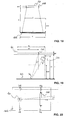
- the spots 34 generated by the two laser aiming devices 30 may particularly be used for checking that the field of view 15 of the camera 10 is perfectly centered and has the desired slope with respect to the supporting plane 102, namely along axis X, and symmetrical with respect to axis Y, or with respect to one or more deflecting mirrors 108 (,109,116%) of the optical reading equipment.
- Figure 11 shows, by way of an example, the case of a rotation (misalignment in plane X,Z) between the camera 10 and a deflecting mirror 108 arranged between the camera 10 and the supporting plane 102.
- the field of view 16' of the camera 10 at mirror 108 is shown.
- the laser spots 34' generated by laser beams 31 at mirror 108 are external to the centerline 108' of mirror 108, particularly they are one (the left one) above the centerline 108' and one (the right one) below it.
- Such an arrangement of the laser spots 34' is indicative of a misalignment (rotation) between the camera 10 and the first mirror 108, a misalignment that, in the absence of the aiming devices 30, would not be detectable by the installer.
- Figures 12 and 13 show, by way of an example, the case of errors of the parallelism between the axis A of the objective of the camera 10 and the axis A' of the mirror 108 (misalignment in plane X,Y), which turn out in a displacement of the laser spots 34' along the centerline 108' of mirror 108. More particularly, the laser spots 34' are not equally spaced from the axis of mirror 108, or from its edges.
- the various misalignments may be present in combination, and will be analogously detectable by the visual indication provided by the laser spots 34' on the plane of mirror 108.
- the spots 34 generated by the laser beams 31 at the supporting plane 102 may be used to check the view angle a downstream of mirror 108, shown in Fig. 14 where the view cone 15 of the camera 10, of the type with a one-dimensional array of photosensors 11, is shown with a dotted line.
- a view angle a must be precisely adjusted because it must have a predetermined value depending on the specific application.
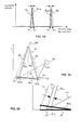
- the installation operation comprises the following steps, described with reference to Figures 15-17:
- the slope a of the view plane of the camera 10 the slope b of the angle of the illuminator and all the mutual positions between camera, any mirrors present within the container 20, and illuminator, are checked at factory.
- centering of the camera 10 in above-mentioned step 1) may be avoided, because centering errors are detectable at any rate from the position of the spots 34 on the supporting plane 102 in above-mentioned step 5).
- the installation operation comprises the following steps (see Figures 18-20):
- the provision of the aiming devices 30 according to the present invention may advantageously allow carrying out a diagnostic function capable of detecting dangerous misalignments of the optical equipment occurred during the normal operation of reading optical information.
- aiming devices 30 may periodically provide indications on the status of the alignment of the equipment.
- the two laser aiming devices 30 are kept turned on, and the image (preferably with the illuminator 121 turned off) obtained by the array of CCD or C-MOS photosensors 11 is stored, the image acquired by the camera 10 shows a luminosity peak at each laser spot 34.
- Figure 21 schematically shows the luminous intensity detected by the camera 10 along the view line 16 in the above described conditions.
- X1 and X2 should be constant over time. If, for any reason, the optical equipment/supporting plane system misaligns, the laser spots 34 tend, even if to a low degree, to displace, and therefore the distances tend to change, or also one or each of the laser spots 34 tend to disappear from the view line 16.
- the displacement of the spots from the position indicated with 34 when the alignment is correct (view line 16) to the position indicated with 34a when a misalignment occurred (view line 16a) is shown in Figure 22 and highlighted in Figure 23, which is a partial enlargement thereof.
- the displacement of the luminosity peaks, and the change in the distances from X1, X2 to X1', X2', are shown in Figure 24.
- the comparison may automatically occur through suitable software, hardware or firmware comparison means within the electronics of the camera 10.
- a greater sensitivity to the alignment changes may be obtained by arranging two aiming devices 40, alternatively or in addition to the two aiming devices 30, externally of the camera 10, and with independent optical path, for example as illustrated in Figure 25 and as highlighted in Figure 26, which is a partial enlargement thereof.
- Such aiming devices 40 generating laser beams 41 are shown.
- the laser beams 41 form the spots 42 on the supporting plane 102, internally of the view line 16 in case of a correct alignment of the equipment, and the spots 42a internally of the view line 16a in case of misalignment.
- 35, 35a lines representing the optical path of the images of the spots 42, 42a seen by the camera 10 are indicated.
- a very advantageous alternative, not strictly necessary for the alignment function, but extremely useful for the diagnostic function, even if more expensive, may be represented by the use of modulated laser light aiming devices, and of corresponding receivers of the same laser radiation.
- light modulation allows measuring the distance between the source and the receiver from the phase difference between the emitted and the received signal (phase shift), namely practically allows measuring the distance between the source and the supporting plane 102 or other element reflecting the laser beam that is interposed in the optical path of the laser beam.
- an information on the distance between the aiming device 30 and the supporting plane 102 may thus be obtained. Therefore, when the aiming device is integral with the camera 10, the distance between the camera 10 and the supporting plane 102 may be calculated.
- analogous devices may be used, based however on the principle of measurement of the "time of flight" of a laser pulse, as is well-known to the skilled in the art.
- the measurement of the distance between the camera 10 and the supporting plane 102 may be carried out immediately after the installation, and it may be periodically checked to ensure that no misalignment occurred, alternatively or in addition to the measurement, storing and comparison of the distances X1,X2,X1',X2' of the laser spots 34, 42 within the scan line.
- this alternative allows for a greater precision of the periodic check of the status of alignment of the optical equipment, because errors of less than a centimeter may be measured.
- a further advantage of this solutions is that it is possible to carry out a complete check operation also during the normal operation of the system, because it does not require the analysis of the image detected by the camera 10 (and thus it does not interrupt the normal acquisition of the information associated to the objects).
- this operation could alter the acquired image (and therefore the reading) due to the presence of the laser spots 34 within the image itself, this operation will preferably be carried out on a sample parcel or on known surfaces between parcels, for example the surface of one of the platforms of a platform conveyor belt 102.
- the checking operation may be continuous.
- Figure 27 is a block diagram summarizing the method for the diagnostic of the alignment of the present invention.
- a block 200 there may be a first step of switching on the aiming devices (block 201), followed by a step of installation of the optical reading equipment (block 202).
- Block 201 is shown as optional, in that the method of the invention may be equally applied in case the equipment is installed with traditional methods, namely without the aid of aiming devices 30.
- the step 202 of installation of the equipment is followed by a second step of switching on the aiming devices 30, 40 (block 203).
- a second step 203 of switching on the aiming devices is conversely omitted in case the first step 201 of switching on the aiming devices has already been carried out for all the aiming devices 30, 40 present.
- the method goes on to a first step of acquisition of an image of the luminous aiming figure 34, 42 generated by the aiming devices 30, 40 (block 204).
- a step of acquisition 204 is carried out through the camera 10 itself or through special photodetectors, distinct therefrom.
- the first step 204 of acquisition is followed (block 205) by a step of storing the values of characteristic parameters of the image acquired in the first step 204 of acquisition.
- characteristic parameters may comprise the presence or the position within the image of at least a point of the luminous aiming figure and/or the measure of the distance between the light source of each aiming device 30 and a detector associated thereto.
- the step 205 of storing the values of characteristic parameters is followed by an optional step of switching off the aiming devices 30, 40 (block 206), which will preferably occur especially when the luminous aiming figure 34, 42 is within the field of view 16 of the camera 10.
- the method goes on in either case with a step of normal use of the optical equipment for reading optical information (block 207).
- the method may provide for a third step of switching on the aiming devices 30, 40 (block 208). It will be understood that whether or not the third step 208 of switching on the aiming devices 30, 40 is carried out in an execution of the method of the invention depends on whether or not the step 206 of switching off the aiming devices is carried out.
- the method goes on in either case with a second step of acquisition of an image of the luminous aiming figure 34, 42 generated by the aiming device 30, 40 (block 209).
- the second step of acquisition 209 also occurs through the camera 10 itself or through the suitable photodetectors, distinct therefrom.
- the second step of acquisition 209 is followed by a step (block 210) of detecting the values of the above-mentioned characteristic parameters of the image acquired in the second step 209 of acquisition.
- the step 210 of detecting the values of the characteristic parameters is followed by a step (block 211) of comparison between the values stored in the step of storing 205 and the values detected in the step of detecting 210.
- the method returns to the normal use of the optical reading equipment (block 207), possibly preceded by the switching off of the aiming devices (block 206) .
- the method provides for a step of re-alignment of the equipment (block 212) before returning to the normal use of the optical reading equipment (block 207), possibly preceded by the switching off of the aiming devices (block 206).
- the step 212 of re-alignment of the equipment may be manual, at the most with the generation of an alarm signal, or it can be totally automated through the actuation of motors for correcting the position of the components of the optical reading equipment.
- the laser beams 31 generated by the aiming devices 30 may be parallel to the field of view 16 of the camera 10, but not coplanar with the field of view 16.
- the laser spots 34 strike two mirrors 36 arranged externally to the main optical path, namely externally to the field of view 15 of the camera 10, but integral with the deflecting mirror 108, and forming a predetermined angle ⁇ therewith.
- each laser aiming device 30 strikes exactly the emitter, a special photoreceiver or, in any case, a predetermined target for a visual comparison by an operator.
- the laser aiming devices 30 may generate beams 31 that initially converge, and then cross before the supporting plane.
- the enhancement of the differences between the positions X1', X2' of the laser spots 34' and the positions X1, X2 of the spots 34 at a correct alignment is maximized, in that the angle formed by the two beams 31 in case of converging beams is greater than in case of diverging beams.
- the aiming devices 30 may also be arranged aligned and symmetrical with respect to the optical axis of the camera 10, but one above and the other below the array of photosensors 11. It will be appreciated that aiming devices so arranged allow just as well the installation of the camera 10, which will occur by checking that the extremes of the luminous aiming figure (namely, the spots 34) lie along a longitudinal axis of the supporting plane 102 or along a transversal axis of the deflecting mirror or mirrors 108 (,109,116,...) at equal distances from the edges.
- the number of aiming devices 30 may be different from two. For example, one could think of using a different number of lasers, even a single laser suffices for the function of diagnostic of the alignment described above, as will be manifest.
- the laser spots 34 generated by the four beams 31 reduce to two, highlighting the view line 16, while at lower distances, the laser beams 31 generate four laser spots 34', delimiting a rectangular zone containing the view cone 15 of the camera 10.
- the aiming figures produced may be circular, linear, cross-shaped etceteras, by using a diaphragm placed between each laser and its objective.
- a aiming line may be generated in lieu of single spots, for example by using, downstream of each laser, an objective with cylindrical lenses or a moving (rotary or oscillating) mirror, as is for example used for scanning the laser beam in the optical code readers using laser technology.
- the mirror could, for example, be arranged below the receiving objective of the camera.
- beam splitters may be used to reduce the number of lasers, the number of generated spots being equal.
- a single laser source may be mounted on a side of the camera 10 and with two beam splitters, or a beam splitter and a mirror, another virtual source may be created on the other side.
- sources different from laser sources may be used, for example LED sources or also filament bulbs associated with fiber optics.
- the LED sources may be associated with a diaphragm and/or an objective, as stated above for the laser aiming devices.
- such sources may be arranged on the side of and in the same plane as the array of CCD photosensors 11, so as to exploit the main objective 12 in lieu of using an objective for each aiming device.
- Figure 30 illustrates such an arrangement, wherein two LED or laser sources are arranged above the array of photosensors 11 and two LED or laser sources are arranged below it, both pairs being symmetrical with respect to the vertical axis of the array of photosensors 11.
- the sensing area of the array of photosensors 11 is further illustrated with 11'.
- Figure 31 illustrates the view line 16 and the four spots 34 of the luminous aiming figure on the supporting plane 102 (or on a deflecting mirror 108).
- use of only two laser or LED sources may be provided, possibly with diaphragms, or two fiber optics ends, arranged along the longitudinal or transverse centerline and at the two sides of the array of photosensors 11, preferably in contact with it.
Applications Claiming Priority (1)
| Application Number | Priority Date | Filing Date | Title |
|---|---|---|---|
| EP02425147A EP1345157B1 (de) | 2002-03-13 | 2002-03-13 | Feste optische Kamera mit Visiermittel |
Related Parent Applications (1)
| Application Number | Title | Priority Date | Filing Date |
|---|---|---|---|
| EP02425147A Division EP1345157B1 (de) | 2002-03-13 | 2002-03-13 | Feste optische Kamera mit Visiermittel |
Publications (2)
| Publication Number | Publication Date |
|---|---|
| EP1798663A2 true EP1798663A2 (de) | 2007-06-20 |
| EP1798663A3 EP1798663A3 (de) | 2009-06-03 |
Family
ID=27763490
Family Applications (2)
| Application Number | Title | Priority Date | Filing Date |
|---|---|---|---|
| EP02425147A Expired - Lifetime EP1345157B1 (de) | 2002-03-13 | 2002-03-13 | Feste optische Kamera mit Visiermittel |
| EP06026253A Withdrawn EP1798663A3 (de) | 2002-03-13 | 2002-03-13 | Optische Festkamera-Leseeinrichtung und Verfahren zur Installation und Ausrichtungsdiagnose |
Family Applications Before (1)
| Application Number | Title | Priority Date | Filing Date |
|---|---|---|---|
| EP02425147A Expired - Lifetime EP1345157B1 (de) | 2002-03-13 | 2002-03-13 | Feste optische Kamera mit Visiermittel |
Country Status (4)
| Country | Link |
|---|---|
| US (2) | US20030174209A1 (de) |
| EP (2) | EP1345157B1 (de) |
| AT (1) | ATE349046T1 (de) |
| DE (1) | DE60216888T2 (de) |
Families Citing this family (13)
| Publication number | Priority date | Publication date | Assignee | Title |
|---|---|---|---|---|
| TW200818875A (en) * | 2006-10-03 | 2008-04-16 | Appro Technology Inc | Monitoring camera and monitoring system using with function of laser positioning |
| US8233040B2 (en) * | 2006-12-01 | 2012-07-31 | Accu-Sort Systems, Inc. | Modular camera and camera system |
| US20080156619A1 (en) * | 2006-12-01 | 2008-07-03 | Mehul Patel | Range finder |
| US8308070B2 (en) | 2008-04-17 | 2012-11-13 | Datalogic Automation S.R.L. | System for automatically acquiring optically coded information, illuminator for said system and method for aligning with each other optical components of the system |
| KR101023275B1 (ko) * | 2009-04-06 | 2011-03-18 | 삼성전기주식회사 | 차량용 카메라 시스템의 캘리브레이션 방법 및 장치, 차량용 카메라 시스템의 각도상 오정렬을 판단하는 방법 및 이를 수행하는 전자 제어 유닛 |
| CN101859206A (zh) * | 2009-04-08 | 2010-10-13 | 鸿富锦精密工业(深圳)有限公司 | 触控式显示装置 |
| WO2011116031A2 (en) | 2010-03-15 | 2011-09-22 | Litepanels, Ltd | Led fresnel lighting system including active cooling |
| US10006609B2 (en) | 2011-04-08 | 2018-06-26 | Litepanels, Ltd. | Plug compatible LED replacement for incandescent light |
| US9639730B2 (en) | 2014-10-09 | 2017-05-02 | Datalogic IP Tech Srl | Aiming system and method for machine-readable symbol readers |
| CN108027439B (zh) * | 2015-08-10 | 2022-12-30 | 三角设计公司 | 具有有角度安装激光器及相机的ic装置袋中检测 |
| FR3046990B1 (fr) * | 2016-01-27 | 2019-06-21 | Airbus Operations | Systeme pour aider au guidage au sol d'un aeronef |
| US10339349B2 (en) * | 2017-07-28 | 2019-07-02 | Datalogic Usa, Inc. | Illumination arrangement for long working range line-scan imaging system |
| CN110261842B (zh) * | 2019-07-08 | 2021-09-14 | 北京云迹科技有限公司 | 适用于机器人的探测激光安装位置调整方法及装置 |
Citations (2)
| Publication number | Priority date | Publication date | Assignee | Title |
|---|---|---|---|---|
| US5744790A (en) * | 1996-01-25 | 1998-04-28 | Symbol Technologies, Inc. | Split optics focusing apparatus for CCD-based bar code scanner |
| US5920061A (en) * | 1997-05-29 | 1999-07-06 | Metanetics Corporation | Portable data collection device including imaging assembly with modular high density dataform reader assembly |
Family Cites Families (5)
| Publication number | Priority date | Publication date | Assignee | Title |
|---|---|---|---|---|
| US590061A (en) * | 1897-09-14 | gallien | ||
| US6736321B2 (en) * | 1995-12-18 | 2004-05-18 | Metrologic Instruments, Inc. | Planar laser illumination and imaging (PLIIM) system employing wavefront control methods for reducing the power of speckle-pattern noise digital images acquired by said system |
| US5672858A (en) * | 1994-06-30 | 1997-09-30 | Symbol Technologies Inc. | Apparatus and method for reading indicia using charge coupled device and scanning laser beam technology |
| US6029893A (en) * | 1995-05-22 | 2000-02-29 | Symbol Technologies, Inc. | Optical scanner having a reflected light collector including holographic optical elements |
| US6223988B1 (en) * | 1996-10-16 | 2001-05-01 | Omniplanar, Inc | Hand-held bar code reader with laser scanning and 2D image capture |
-
2002
- 2002-03-13 AT AT02425147T patent/ATE349046T1/de not_active IP Right Cessation
- 2002-03-13 DE DE60216888T patent/DE60216888T2/de not_active Expired - Lifetime
- 2002-03-13 EP EP02425147A patent/EP1345157B1/de not_active Expired - Lifetime
- 2002-03-13 EP EP06026253A patent/EP1798663A3/de not_active Withdrawn
- 2002-12-26 US US10/331,157 patent/US20030174209A1/en not_active Abandoned
-
2007
- 2007-10-03 US US11/866,842 patent/US20080174661A1/en not_active Abandoned
Patent Citations (2)
| Publication number | Priority date | Publication date | Assignee | Title |
|---|---|---|---|---|
| US5744790A (en) * | 1996-01-25 | 1998-04-28 | Symbol Technologies, Inc. | Split optics focusing apparatus for CCD-based bar code scanner |
| US5920061A (en) * | 1997-05-29 | 1999-07-06 | Metanetics Corporation | Portable data collection device including imaging assembly with modular high density dataform reader assembly |
Also Published As
| Publication number | Publication date |
|---|---|
| EP1345157A1 (de) | 2003-09-17 |
| US20030174209A1 (en) | 2003-09-18 |
| DE60216888D1 (de) | 2007-02-01 |
| EP1345157B1 (de) | 2006-12-20 |
| DE60216888T2 (de) | 2007-08-02 |
| EP1798663A3 (de) | 2009-06-03 |
| US20080174661A1 (en) | 2008-07-24 |
| ATE349046T1 (de) | 2007-01-15 |
Similar Documents
| Publication | Publication Date | Title |
|---|---|---|
| US20080174661A1 (en) | Fixed Camera Type Optical Reading Equipment and Methods For Its Installation and For the Diagnostic Of Its Alignment | |
| US6573981B2 (en) | Electronic level | |
| EP2381272B1 (de) | Laserscanner | |
| CN100517366C (zh) | 在光电读取器和图像投影仪中监控光束位置的装置 | |
| CN107957237A (zh) | 具有闪光对准的激光投影仪 | |
| US4171917A (en) | Determining the profile of a surface of an object | |
| US7726573B2 (en) | Compact autofocus bar code reader with moving mirror | |
| KR920003534B1 (ko) | 핀홀 광탐지 장치 | |
| CN111174702B (zh) | 一种自适应结构光投射模组及测量方法 | |
| EP1003050A2 (de) | Lichtstrahl-Ablenkvorrichtung | |
| WO1996005477A1 (en) | High precision semiconductor component alignment systems | |
| CN101151506A (zh) | 用于光学检测产品的边沿的传感器装置和宽度测量方法 | |
| US20210311193A1 (en) | Lidar sensor for optically detecting a field of vision, working device or vehicle including a lidar sensor, and method for optically detecting a field of vision | |
| US20060033935A1 (en) | Laser sheet generator | |
| US10837767B2 (en) | Angle detection system | |
| JP2001124521A (ja) | 光学式位置感知装置 | |
| KR102105715B1 (ko) | 라이다 스캐너 | |
| CN113299575B (zh) | 聚焦方法及装置、聚焦设备和存储介质 | |
| KR20200049726A (ko) | 라이다 스캐너 | |
| JPH03190418A (ja) | レーザ式光電スイッチおよび測距装置 | |
| KR102623088B1 (ko) | Dmd를 구비한 3차원 이미지 장치 및 그 동작 방법 | |
| CN110869801B (zh) | 用于激光雷达系统的激光扫描仪和用于运行激光扫描仪的方法 | |
| JPH04110706A (ja) | 三次元形状データ取込み装置 | |
| JP2000162307A (ja) | 原子炉容器点検ロボットの位置標定用レーザ追尾装置 | |
| EP4020004A3 (de) | Objektdetektor, messvorrichtung und mobiles objekt |
Legal Events
| Date | Code | Title | Description |
|---|---|---|---|
| PUAI | Public reference made under article 153(3) epc to a published international application that has entered the european phase |
Free format text: ORIGINAL CODE: 0009012 |
|
| AC | Divisional application: reference to earlier application |
Ref document number: 1345157 Country of ref document: EP Kind code of ref document: P |
|
| AK | Designated contracting states |
Kind code of ref document: A2 Designated state(s): AT BE CH CY DE DK ES FI FR GB GR IE IT LI LU MC NL PT SE TR |
|
| RTI1 | Title (correction) |
Free format text: FIXED OPTICAL CAMERA HAVING AIMING MEANS |
|
| PUAL | Search report despatched |
Free format text: ORIGINAL CODE: 0009013 |
|
| AK | Designated contracting states |
Kind code of ref document: A3 Designated state(s): AT BE CH CY DE DK ES FI FR GB GR IE IT LI LU MC NL PT SE TR |
|
| 17P | Request for examination filed |
Effective date: 20091102 |
|
| AKX | Designation fees paid |
Designated state(s): AT BE CH CY DE DK ES FI FR GB GR IE IT LI LU MC NL PT SE TR |
|
| 17Q | First examination report despatched |
Effective date: 20110315 |
|
| STAA | Information on the status of an ep patent application or granted ep patent |
Free format text: STATUS: THE APPLICATION IS DEEMED TO BE WITHDRAWN |
|
| 18D | Application deemed to be withdrawn |
Effective date: 20110726 |