EP1003050A2 - Lichtstrahl-Ablenkvorrichtung - Google Patents
Lichtstrahl-Ablenkvorrichtung Download PDFInfo
- Publication number
- EP1003050A2 EP1003050A2 EP00100755A EP00100755A EP1003050A2 EP 1003050 A2 EP1003050 A2 EP 1003050A2 EP 00100755 A EP00100755 A EP 00100755A EP 00100755 A EP00100755 A EP 00100755A EP 1003050 A2 EP1003050 A2 EP 1003050A2
- Authority
- EP
- European Patent Office
- Prior art keywords
- mirror
- spring element
- edge
- unit
- light beam
- Prior art date
- Legal status (The legal status is an assumption and is not a legal conclusion. Google has not performed a legal analysis and makes no representation as to the accuracy of the status listed.)
- Withdrawn
Links
Images


Classifications
-
- G—PHYSICS
- G01—MEASURING; TESTING
- G01S—RADIO DIRECTION-FINDING; RADIO NAVIGATION; DETERMINING DISTANCE OR VELOCITY BY USE OF RADIO WAVES; LOCATING OR PRESENCE-DETECTING BY USE OF THE REFLECTION OR RERADIATION OF RADIO WAVES; ANALOGOUS ARRANGEMENTS USING OTHER WAVES
- G01S7/00—Details of systems according to groups G01S13/00, G01S15/00, G01S17/00
- G01S7/48—Details of systems according to groups G01S13/00, G01S15/00, G01S17/00 of systems according to group G01S17/00
- G01S7/481—Constructional features, e.g. arrangements of optical elements
- G01S7/4817—Constructional features, e.g. arrangements of optical elements relating to scanning
-
- G—PHYSICS
- G01—MEASURING; TESTING
- G01B—MEASURING LENGTH, THICKNESS OR SIMILAR LINEAR DIMENSIONS; MEASURING ANGLES; MEASURING AREAS; MEASURING IRREGULARITIES OF SURFACES OR CONTOURS
- G01B11/00—Measuring arrangements characterised by the use of optical techniques
-
- G—PHYSICS
- G01—MEASURING; TESTING
- G01S—RADIO DIRECTION-FINDING; RADIO NAVIGATION; DETERMINING DISTANCE OR VELOCITY BY USE OF RADIO WAVES; LOCATING OR PRESENCE-DETECTING BY USE OF THE REFLECTION OR RERADIATION OF RADIO WAVES; ANALOGOUS ARRANGEMENTS USING OTHER WAVES
- G01S17/00—Systems using the reflection or reradiation of electromagnetic waves other than radio waves, e.g. lidar systems
- G01S17/02—Systems using the reflection of electromagnetic waves other than radio waves
- G01S17/06—Systems determining position data of a target
- G01S17/08—Systems determining position data of a target for measuring distance only
-
- G—PHYSICS
- G02—OPTICS
- G02B—OPTICAL ELEMENTS, SYSTEMS OR APPARATUS
- G02B26/00—Optical devices or arrangements for the control of light using movable or deformable optical elements
- G02B26/08—Optical devices or arrangements for the control of light using movable or deformable optical elements for controlling the direction of light
- G02B26/10—Scanning systems
- G02B26/12—Scanning systems using multifaceted mirrors
-
- G—PHYSICS
- G02—OPTICS
- G02B—OPTICAL ELEMENTS, SYSTEMS OR APPARATUS
- G02B5/00—Optical elements other than lenses
- G02B5/08—Mirrors
- G02B5/09—Multifaceted or polygonal mirrors, e.g. polygonal scanning mirrors; Fresnel mirrors
Definitions
- This invention relates to an apparatus for measuring the distance to at least part of an object for determining at least one dimension of the object, the apparatus being as defined in the preamble of claim 1.
- Apparatus of this known kind is described in EP-A-0346015, and another known apparatus is disclosed in US-A-4996440. Further, the invention also relates to an apparatus for deflecting a light beam by means of a rotating polygonal mirror unit with each mirror of the unit being individually adjustable.
- An apparatus of this kind is known from US-A-3529884.
- an apparatus as claimed in the ensuing claim 1 for measuring the distance to at least one part of an object for determining at least one dimension of the object.
- the physical object 1 which is to be measured is placed by an operator 2 on a table 3, a weighing scale or another stable, invariable surface.
- the measuring apparatus in FIG. 1 indicated in general by means of the reference numeral 5, is advised that a measurement is required by means of a start signal given via a push button, foot pedal 4, or a command across a serial interface from an external computer (not shown).
- the measuring apparatus 5 is mounted in a measuring carriage 6 which is made to move over the object 1 along a guiding profile 7, whereby the dimensions of the object are read.
- a short time after the carriage 6 has passed over the object 1, the measured dimensions and/or parts thereof, e.g. the volume of the object, will be shown on a display 8.
- the result of the measurement may optionally also be fed to the computer.
- a print-out 9 may optionally also be provided via a printer 10.
- This print-out can, for instance, be in alphanumeric form, in the form of bar code, or optionally in the form of both.
- the print-out may optionally be of a kind such that it can be adhered to the object, so that the dimensions of the object are thus unambiguously defined in connection with possible later handling of the object.
- the measuring apparatus After an output and/or print-out has been given the measuring apparatus will be ready to measure a new object.
- FIG. 2 is related to problems of so-called "fields of shadow".
- the regulations are drawn up in such a way that payment has to be made for the smallest right-angled rectangular box or crate in which the object can be placed. If the path of measurement or the path of the light beam deviates from 90° towards the underlying support 3, a field of shadow 11 will occur, as illustrated in FIG. 2.
- the measuring apparatus will be unable to detect the content of this field of shadow.
- the angle ⁇ that the scanning light beam 12 forms with the vertical should thus be as close to 0° as possible.
- the maximum error of measurement will depend upon how much of an object to be measured is within a shadow area of this kind and that cannot be detected.
- FIG. 3 shows the measuring principle for a laser distance reader, generally denoted by the reference numeral 13.
- An oscillator 14 modulates a laser diode 15 with an FM frequency (e.g. 82 MHz).
- the laser light which is emitted from the laser diode 15 is denoted by reference numeral 16 and passes via a mirror unit 17 downwards at right angles towards the underlying support 3 on which an object may be placed.
- Light reflected back is marked with the reference numeral 18 and travels past the mirror unit 17 via optics 19 to an optical sensor 20, e.g. a photodiode which is capable of registering the received laser light.
- This received light signal is transferred via a connection 21 to an amplifier 22 which has automatic gain control (AGC).
- AGC automatic gain control
- a signal is produced at the first outlet 23 from the amplifier which is characteristic of the received luminous intensity.
- a second outlet 24 from the amplifier 22 is connected to a first input 25 on a phase measuring device 26, and an outlet 27 on the oscillator 14 is connected to a second input 28 on the phase measuring device 26.
- the distance measuring apparatus will measure the distance to the object 1 by measuring the time T1 that the light takes from when the laser beam leaves the distance measuring apparatus, hits the object 1, and is received as reflected light by the sensor 20. This time is measured by measuring, in the phase measuring device 26, the phase difference between the emitted light, as registered at the input 28, and the light reflected back, as registered at the input 25 of the phase measuring device 26. Characteristic distance values are then produced at the output of the phase measuring device 29.
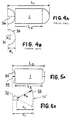
- US-A-4996440 makes known the use of a cone segment mirror to form a generally conical mirror surface to deflect the scanning beam to scan at right angles downwards to the underlying support.
- the necessary gauge length for the measuring carriage will have the value L 1 which is equal to twice the radius R 1 of the conical mirror 30, as shown in FIG. 4B and also the length L 2 of the object as shown in FIG. 4A.
- a polygonal mirror unit 32 is used instead of the rotating plane mirror 31 in FIG. 4B.
- the mirror unit 32 is, in the preferred embodiment, made of six mirror surfaces arranged on the six sides of the polygon.
- a modified paraboloid is used, i.e. a double curved mirror or a parabola, the arc of which has a radius of curvature which is modified somewhat over the length of the mirror. In an embodiment the radius of curvature is greatest at the ends of the mirror.
- modified paraboloid mirror is marked with the reference numeral 33.
- R 3 denotes the length of the measuring carriage which is increased relative to the known R 1 value.
- R 2 is the distance between the centre of the mirror surfaces of the polygonal mirror unit 32 and the mid-point of the double curved mirror 33.
- R 4 generally denotes the radius of curvature of the mirror 33. However, it should be pointed out that R 2 will change gradually as the mirror 32 rotates and that this is compensated by the design of the double curved mirror 33.
- the effective measuring length that the measuring carriage must move will be equal to L 3 , which is twice the pitch 35 plus the length L 2 of the object 1.
- the measuring length will be related to effective scanning time over the object.
- the conical mirror 30 spans over an angle which is almost equal to 180°.
- the pitch 36 of this arc will be large.
- a reduction in the length of the apparatus or guiding rail 7 is achieved when the pitch 35 is reduced.
- the scanning angle for the fan-shaped scan will thus also be smaller.
- This in turn means that it is possible to use a plurality of mirror surfaces in the polygon and to rotate the polygon at a lower speed of rotation for the same scanning frequency as is used in the known solution according to FIG. 4.
- the most substantial disadvantage with the solution which is outlined in FIG. 5 is that the length of the measuring carriage in the direction of movement will be greater owing to the increased radius between the polygonal mirror unit and the double curved mirror 33.
- the distance between the centre of the mirror surfaces of the polygonal mirror unit and the mid-point of the double curved mirror 33 is equal to R 2 as shown in FIG. 5B.
- the length of the measuring carriage will, however, be considerably reduced in that the scanning beam, which spreads out in a fan shape, will be deflected 90° twice by means of two mirrors 37 and 38 which form an angle of 90° in relation to one another, the light beam being reflected from the mirror unit 32 towards the mirror 37, thence to the mirror 38, and on further to a double curved mirror 39 so that, in the example shown in FIG.
- the distance between a centre of the mirror surface of the polygonal mirror unit and the mid-point of the double curved mirror 39 has a distance R 5 .
- this solution groups the optics in two sets of mirror surfaces which are mounted directly above/below one another. As long as an even number of mirror surfaces are closely connected to one another at fixed angles in relation to one another, a rotation or translation of the two connected mirrors, which together form one system, will be of no consequence for the angle at which the light leaves the mirrors taken as a whole.
- the two folding or deflecting mirrors 37 and 38 are connected to one another in one system and the polygonal mirror unit 32 and the double curved mirror 39 are connected together in a second system within the present apparatus.
- the laser distance measuring device 13 will, by means of its laser, emit a light beam 16 in the direction of the mirror 17, whence the light beam 16 is reflected in the direction of the rotating polygonal mirror unit 32.
- This unit has, for instance, six mirror surfaces 40 mounted on the side surfaces of the polygon. Each mirror has been given a size that has been determined by the aperture of the receiving optical means 19.
- the laser light will be dispersed in a fan shape from the polygonal mirror unit 32 as this rotates. This fan-shaped light will be deflected by the mirrors 37 and 38 which are mounted at 90° relative to one another. The scanning light beam or laser light fan will thus hit a large double curved deflecting mirror 39.
- This mirror will deflect the received light beam 90° so that the light scans at right angles downwards to the underlying support 3 which is found under the measuring apparatus.
- This light that has been reflected from the object will be, as explained earlier, detected and the phase difference between the emitted laser light and the received laser light will, as previously mentioned, form the basis for calculating successive distances to the object 1 which is on the support 3.
- the light which is reflected from the object will be led via the double curved mirror 39 to the lower deflecting mirror 38, thence to the upper deflecting mirror 37, thence to the polygonal mirror unit 32, and thence via the optical means 19 to the detector 20.
- the polygonal mirror unit 32 will be driven by a motor 41, where the mirror unit constitutes a part of the motor rotor, and where the motor central stator is via a suspension or shaft 42 rigidly connected to a framework or other mounting means in the measuring carriage.
- a laser distance measuring apparatus such as the one described and illustrated here, will be capable of being exposed to a certain drift in the measurement values over time, for example because of temperature changes, aging, variation between models, etc.. It will therefore be both desirable and necessary to calibrate the distance measuring apparatus whilst it is in operation.
- the light will be deflected here so as to pass through a window 45 and hit an end 46 of the guide rail or guide profile 7.
- a small plate 47 which has been given a grey toned pattern is positioned at the end 46 and from here measurements are taken during each scan.
- the trigger diodes 44 and 48 will emit a signal when the light beam meets the diodes, where starting and stopping of a scan will be indicated. This will also give a fairly reliable determination of the momentary position of the light beam along the double curved mirror 39 when the speed of the motor 41 is known or is constant, so that it can be measured exactly by means of the trigger diodes.
- a polygonal mirror unit 32 is used, the task of which being to spread out the laser beam and to pick up the light spread towards the receiver in a fan shape, as previously described, so that the object to be measured is scanned in one axial direction.
- the paths of light must be so precise that the scanning paths will be monotonously ascending with the direction of movement of the measuring carriage.
- the diameter of the polygonal unit is determined by a necessary aperture for the receiving lenses and the number of mirrors that are necessary for the desired scanning angle.
- the angle of the mirrors along the direction of rotation is assumed to be non-critical, since this will only cause a time displacement of the scan. This could be compensated for by the light passing the trigger diode 44 immediately prior to the start of the scan, and the trigger diode 48 immediately after the end of the double curved mirror 39 thereby registering the time of the end of the scan.
- the angle of the mirror transverse to the direction of rotation must however deviate very little from mirror to mirror, and in the present embodiment of the invention this angle deviation must typically be ⁇ 1 milliradian.
- the angle of the mirrors will be adjustable, according to the invention, by means of an apparatus such as the one in FIGS. 11 and 12.
- the polygonal unit here is made with the shaft 49 of the driving motor 41 and thus the stator of the motor secured to a holder 50 for the polygonal mirror unit.
- the motor housing will thus be connected to the mirrors 40 which are a part of the unit 32, the motor housing rotating together with the mirrors 40.
- the mirrors are deposited in a holder 51 which fixes the under side of the mirrors at two points 52 and 53.
- the upper side of the mirrors are supported at one point by a flexible metal plate 54.
- the plate 54 has, moreover, two punched-out tongues 55 and 56 which project from the centre of the metal plate 54 and come to bear against the back of the mirror in order to press the mirror out towards its abutment points uppermost and lowermost.
- a screw connection 57 causes the mirror bottom holder 51 and the flexible metal plate 54 to be held together. By tightening the screw connection 57, the metal plate 54 will be bent together, whereby the upper side of the mirror 40 will be drawn in the direction of the mid-point of the polygonal unit.
- the polygonal mirror unit is connected to the laser distance measuring apparatus 13, which can be firmly fixed to the holder 50 in such a way that the polygonal unit and the laser distance measuring apparatus thereby have their position relative to one another fixed.
- the mirrors 40 in the polygonal unit will be adjustable to the correct and possibly identical angles by manually rotating the polygonal unit 32 and observing the light path of the laser on a screen at a distance that is sufficient to make possible an accurate adjustment of the position of the paths of light.
- a pin 58 is arranged on the polygonal unit which extends down from the polygonal unit and will interrupt a light beam when it passes a light fork.
- the pin is used to identify the position of the polygon by communication with a computer so that the computer knows which of the mirrors is used in the scan at any point of time.
- the computer will be able to include possible remaining errors in the mirror angles of the polygonal unit so that such errors can be included in the calibrating algorithms of the computer.
- An ideal, fan-shaped scan is generated by a mirror which rotates around an axis which is placed in the centre of the mirror in the plane of the reflecting coating.
- the scan constitutes approximately 60°. If a double-sided mirror is used, only twice 30° of a 360°-rotation could be used which would give rise to poor efficiency in terms of time.
- the mirror surfaces are used which are assembled in a polygon, where the diameter of the polygon is determined by the size of each mirror.
- the mirror surfaces will, in this way, be displaced from the centre of rotation and this will give rise to a fan-shaped scan where the centre of rotation will, in reality, move during rotation.
- the consequence of this in the present case will be that the scanning beams which sweep over the object will not be parallel if a paraboloid is used as a double curved mirror.
- the form of this mirror is therefore modified in relation to a rotated parabola, so that the light will travel parallel down towards the object 1. This is done in practice by changing the radius value and also the position of the radius centre for the rotated parabola sufficiently along the mirror, the opposite of what will happen to the polygon after the polygon scans over the double curved mirror, whereby the error will be compensated.
- FIG. 13 shows in more detail how the foot of the reflected beam moves along the mirror surface (and the position of the centre of the fan-shaped scan) as the mirror surface 40 rotates.
- a first position 59 for the mirror unit 32 the distance between the foot point of the beam and the centre of the mirror unit is d 3 .
- the angle between the incident beam 16 and the reflected beam 18 is equal to approximately 90°.
- the polygonal unit 32 is at position 60 (which can be seen in FIG. 13) the reflection point or foot point of the incident beam 16 will have changed so that the distance from the centre will now have increased to d 4 .
- a special feature is the design of the double curved mirror, whereby this is given a focusing power which enables the lens system to be moved effectively much closer to the object which is to be measured.
- the solid angle with which one can observe the laser spot will increase, for a given area, inversely proportional to the square of the distance. It is therefore essential to make the distance that the laser beams move as short as possible and thereby achieve the best possible accuracy of measurement.
- the necessary dimension is reduced for the subsequent components which are positioned after the first focusing mirror, especially folding mirror, polygonal mirror and lenses which are mounted right in front of the sensor unit.
Applications Claiming Priority (3)
| Application Number | Priority Date | Filing Date | Title |
|---|---|---|---|
| NO931741 | 1993-05-13 | ||
| NO931741A NO301191B1 (no) | 1993-05-13 | 1993-05-13 | Anordning ved måling av gjenstanders dimensjoner |
| EP94916438A EP0705445B1 (de) | 1993-05-13 | 1994-05-13 | Gerät zur messung abmessungen eines objektes |
Related Parent Applications (1)
| Application Number | Title | Priority Date | Filing Date |
|---|---|---|---|
| EP94916438A Division EP0705445B1 (de) | 1993-05-13 | 1994-05-13 | Gerät zur messung abmessungen eines objektes |
Publications (2)
| Publication Number | Publication Date |
|---|---|
| EP1003050A2 true EP1003050A2 (de) | 2000-05-24 |
| EP1003050A3 EP1003050A3 (de) | 2000-06-28 |
Family
ID=19896087
Family Applications (2)
| Application Number | Title | Priority Date | Filing Date |
|---|---|---|---|
| EP94916438A Expired - Lifetime EP0705445B1 (de) | 1993-05-13 | 1994-05-13 | Gerät zur messung abmessungen eines objektes |
| EP00100755A Withdrawn EP1003050A3 (de) | 1993-05-13 | 1994-05-13 | Lichtstrahl-Ablenkvorrichtung |
Family Applications Before (1)
| Application Number | Title | Priority Date | Filing Date |
|---|---|---|---|
| EP94916438A Expired - Lifetime EP0705445B1 (de) | 1993-05-13 | 1994-05-13 | Gerät zur messung abmessungen eines objektes |
Country Status (8)
| Country | Link |
|---|---|
| US (2) | US5742068A (de) |
| EP (2) | EP0705445B1 (de) |
| JP (1) | JP3287850B2 (de) |
| AT (1) | ATE195813T1 (de) |
| AU (1) | AU6817094A (de) |
| DE (1) | DE69425659T2 (de) |
| NO (1) | NO301191B1 (de) |
| WO (1) | WO1994027166A1 (de) |
Cited By (5)
| Publication number | Priority date | Publication date | Assignee | Title |
|---|---|---|---|---|
| US6705526B1 (en) | 1995-12-18 | 2004-03-16 | Metrologic Instruments, Inc. | Automated method of and system for dimensioning objects transported through a work environment using contour tracing, vertice detection, corner point detection, and corner point reduction methods on two-dimensional range data maps captured by an amplitude modulated laser scanning beam |
| US6971580B2 (en) | 1999-06-07 | 2005-12-06 | Metrologic Instruments, Inc. | Automated method of and system for dimensioning objects over a conveyor belt structure by applying contouring tracing, vertice detection, corner point detection, and corner point reduction methods to two-dimensional range data maps of the space above the conveyor belt captured by an amplitude modulated laser scanning beam |
| US7344082B2 (en) | 2002-01-02 | 2008-03-18 | Metrologic Instruments, Inc. | Automated method of and system for dimensioning objects over a conveyor belt structure by applying contouring tracing, vertice detection, corner point detection, and corner point reduction methods to two-dimensional range data maps of the space above the conveyor belt captured by an amplitude modulated laser scanning beam |
| CN101685193B (zh) * | 2008-09-24 | 2011-08-17 | 北京航天计量测试技术研究所 | 光学用弹性连接组件及采用该组件的正多面棱体 |
| KR20210042354A (ko) * | 2018-08-10 | 2021-04-19 | 블랙모어 센서스 앤드 애널리틱스, 엘엘씨 | 콜리메이트된 빔들의 팬을 이용한 코히런트 lidar의 스캐닝을 위한 방법 및 시스템 |
Families Citing this family (23)
| Publication number | Priority date | Publication date | Assignee | Title |
|---|---|---|---|---|
| AT403739B (de) * | 1995-05-18 | 1998-05-25 | Gec Alsthom T & D Ges Mbh | Einrichtung zum erfassen der masse eines bewegten gegenstandes |
| US5661561A (en) | 1995-06-02 | 1997-08-26 | Accu-Sort Systems, Inc. | Dimensioning system |
| US6456415B1 (en) * | 1999-06-02 | 2002-09-24 | Fuji Photo Film Co., Ltd. | Optical scanner |
| US7087892B2 (en) * | 2000-08-18 | 2006-08-08 | Matsushita Electric Industrial Co., Ltd. | Light scanner and image forming apparatus using the same |
| WO2002080510A1 (en) * | 2001-03-30 | 2002-10-10 | Gregory Jon Tarrant | Apparatus and method for service calling |
| WO2006034144A2 (en) | 2004-09-18 | 2006-03-30 | The Ohio Willow Wood Company | Apparatus for determining the three dimensional shape of an object |
| US8294809B2 (en) | 2005-05-10 | 2012-10-23 | Advanced Scientific Concepts, Inc. | Dimensioning system |
| US20070272732A1 (en) * | 2006-05-26 | 2007-11-29 | Mettler-Toledo, Inc. | Weighing and dimensioning system and method for weighing and dimensioning |
| DE102006055992B4 (de) | 2006-11-28 | 2010-09-23 | Leuze Electronic Gmbh & Co Kg | Barcodelesegerät |
| US7525670B1 (en) * | 2008-04-02 | 2009-04-28 | Eastman Kodak Company | Distance and orientation measurement of an object |
| TWI386619B (zh) * | 2008-10-08 | 2013-02-21 | Nat Applied Res Laboratories | 旋轉物體形貌變化的測量方法與測量設備 |
| WO2011032999A1 (en) | 2009-09-15 | 2011-03-24 | Mettler-Toledo Ag | Apparatus for measuring the dimensions of an object |
| US9090315B1 (en) * | 2010-11-23 | 2015-07-28 | Piedra—Sombra Corporation, Inc. | Optical energy transfer and conversion system |
| US9618742B1 (en) | 2013-03-08 | 2017-04-11 | Google Inc. | Rotatable mirror assemblies |
| JP6484981B2 (ja) * | 2014-09-30 | 2019-03-20 | 日亜化学工業株式会社 | 照明装置及び灯具 |
| EP3203264A1 (de) | 2016-02-04 | 2017-08-09 | Mettler-Toledo GmbH | Verfahren zur abbildung eines objekts zur verfolgung und dokumentation beim transportieren und lagern |
| EP3203180B1 (de) | 2016-02-04 | 2018-12-05 | Mettler-Toledo GmbH | Vorrichtung und verfahren zur dimensionierung eines objekts, das von einem fahrzeug getragen wird, das sich in einem messfeld bewegt |
| CN108225175B (zh) * | 2017-12-06 | 2023-05-02 | 浙江大学 | 拖拉机传动系锥齿轮齿面接触印痕数据获取装置与方法 |
| US11536845B2 (en) | 2018-10-31 | 2022-12-27 | Waymo Llc | LIDAR systems with multi-faceted mirrors |
| US10786925B1 (en) * | 2020-02-21 | 2020-09-29 | OnSize Inc. | Optical method and apparatus for measuring objects |
| US10942277B1 (en) | 2020-06-19 | 2021-03-09 | Aurora Innovation, Inc. | LIDAR system |
| CN116829977A (zh) * | 2021-02-02 | 2023-09-29 | 微视公司 | 具有用于感测低能量反射的检测器的扫描激光装置和方法 |
| CN114527566A (zh) * | 2022-01-19 | 2022-05-24 | 洛伦兹(宁波)科技有限公司 | 转镜装置的制作方法 |
Citations (6)
| Publication number | Priority date | Publication date | Assignee | Title |
|---|---|---|---|---|
| US3529884A (en) * | 1968-04-03 | 1970-09-22 | Ncr Co | Scanning polygon mirror assembly |
| US4043632A (en) * | 1975-05-27 | 1977-08-23 | Data General Corporation | Scanning polygon with adjustable mirrors |
| DE3106914A1 (de) * | 1981-02-25 | 1982-09-09 | Olympia Werke Ag, 2940 Wilhelmshaven | Drehbarer mehrflaechenspiegel in einem optischen system |
| EP0346015A2 (de) * | 1988-06-04 | 1989-12-13 | Fujitsu Limited | Optisches System zur Ermittlung einer dreidimensionalen Form |
| US4996440A (en) * | 1989-06-22 | 1991-02-26 | Tomra Systems A/S | Device for measuring dimensions |
| US5012079A (en) * | 1989-11-13 | 1991-04-30 | Lazerdata Corporation | Bar code scanner mirror assembly |
Family Cites Families (10)
| Publication number | Priority date | Publication date | Assignee | Title |
|---|---|---|---|---|
| US3943361A (en) * | 1974-08-07 | 1976-03-09 | Oregon Graduate Center For Study And Research | Dimensional measurement of remote objects using projected light raster |
| US4433894A (en) * | 1981-11-12 | 1984-02-28 | Lincoln Laser Company | Method and apparatus for generating optical scans |
| JPS59100862A (ja) * | 1982-12-01 | 1984-06-11 | Hitachi Ltd | 自動分析装置 |
| US4692629A (en) * | 1985-06-10 | 1987-09-08 | Mitutoyo Mfg., Co., Ltd. | Optical type measuring scanner |
| US4759593A (en) * | 1986-03-21 | 1988-07-26 | Eastman Kodak Company | High resolution optical scanner |
| DE3819058A1 (de) * | 1988-06-04 | 1989-12-07 | Zwick Gmbh & Co | Verfahren zur quasisimultanen messung der laengen- und/oder breiten- und/oder dickenaenderung an laenglichen werkstoffproben und vorrichtung zur durchfuehrung des verfahrens |
| US5005928A (en) * | 1988-07-15 | 1991-04-09 | Ricoh Company, Ltd. | Optical scanning system |
| EP0503167B1 (de) * | 1991-03-12 | 1995-06-14 | Matsushita Electric Works, Ltd. | Rauchmelder und Verfahren zum Testen eines solchen Melders |
| JPH05333268A (ja) * | 1992-06-03 | 1993-12-17 | Matsushita Electric Ind Co Ltd | 円弧照明装置 |
| JP3060912B2 (ja) * | 1995-09-11 | 2000-07-10 | 富士通株式会社 | 回転多面鏡およびその製造方法 |
-
1993
- 1993-05-13 NO NO931741A patent/NO301191B1/no not_active IP Right Cessation
-
1994
- 1994-05-13 AT AT94916438T patent/ATE195813T1/de not_active IP Right Cessation
- 1994-05-13 AU AU68170/94A patent/AU6817094A/en not_active Abandoned
- 1994-05-13 DE DE69425659T patent/DE69425659T2/de not_active Expired - Lifetime
- 1994-05-13 EP EP94916438A patent/EP0705445B1/de not_active Expired - Lifetime
- 1994-05-13 EP EP00100755A patent/EP1003050A3/de not_active Withdrawn
- 1994-05-13 JP JP52528394A patent/JP3287850B2/ja not_active Expired - Lifetime
- 1994-05-13 US US08/545,801 patent/US5742068A/en not_active Expired - Lifetime
- 1994-05-13 WO PCT/NO1994/000090 patent/WO1994027166A1/en active IP Right Grant
-
1997
- 1997-09-12 US US08/927,803 patent/US5917640A/en not_active Expired - Lifetime
Patent Citations (6)
| Publication number | Priority date | Publication date | Assignee | Title |
|---|---|---|---|---|
| US3529884A (en) * | 1968-04-03 | 1970-09-22 | Ncr Co | Scanning polygon mirror assembly |
| US4043632A (en) * | 1975-05-27 | 1977-08-23 | Data General Corporation | Scanning polygon with adjustable mirrors |
| DE3106914A1 (de) * | 1981-02-25 | 1982-09-09 | Olympia Werke Ag, 2940 Wilhelmshaven | Drehbarer mehrflaechenspiegel in einem optischen system |
| EP0346015A2 (de) * | 1988-06-04 | 1989-12-13 | Fujitsu Limited | Optisches System zur Ermittlung einer dreidimensionalen Form |
| US4996440A (en) * | 1989-06-22 | 1991-02-26 | Tomra Systems A/S | Device for measuring dimensions |
| US5012079A (en) * | 1989-11-13 | 1991-04-30 | Lazerdata Corporation | Bar code scanner mirror assembly |
Cited By (5)
| Publication number | Priority date | Publication date | Assignee | Title |
|---|---|---|---|---|
| US6705526B1 (en) | 1995-12-18 | 2004-03-16 | Metrologic Instruments, Inc. | Automated method of and system for dimensioning objects transported through a work environment using contour tracing, vertice detection, corner point detection, and corner point reduction methods on two-dimensional range data maps captured by an amplitude modulated laser scanning beam |
| US6971580B2 (en) | 1999-06-07 | 2005-12-06 | Metrologic Instruments, Inc. | Automated method of and system for dimensioning objects over a conveyor belt structure by applying contouring tracing, vertice detection, corner point detection, and corner point reduction methods to two-dimensional range data maps of the space above the conveyor belt captured by an amplitude modulated laser scanning beam |
| US7344082B2 (en) | 2002-01-02 | 2008-03-18 | Metrologic Instruments, Inc. | Automated method of and system for dimensioning objects over a conveyor belt structure by applying contouring tracing, vertice detection, corner point detection, and corner point reduction methods to two-dimensional range data maps of the space above the conveyor belt captured by an amplitude modulated laser scanning beam |
| CN101685193B (zh) * | 2008-09-24 | 2011-08-17 | 北京航天计量测试技术研究所 | 光学用弹性连接组件及采用该组件的正多面棱体 |
| KR20210042354A (ko) * | 2018-08-10 | 2021-04-19 | 블랙모어 센서스 앤드 애널리틱스, 엘엘씨 | 콜리메이트된 빔들의 팬을 이용한 코히런트 lidar의 스캐닝을 위한 방법 및 시스템 |
Also Published As
| Publication number | Publication date |
|---|---|
| NO301191B1 (no) | 1997-09-22 |
| AU6817094A (en) | 1994-12-12 |
| EP0705445A1 (de) | 1996-04-10 |
| WO1994027166A1 (en) | 1994-11-24 |
| DE69425659T2 (de) | 2001-05-03 |
| JPH08510328A (ja) | 1996-10-29 |
| EP0705445B1 (de) | 2000-08-23 |
| ATE195813T1 (de) | 2000-09-15 |
| NO931741L (no) | 1994-11-14 |
| NO931741D0 (no) | 1993-05-13 |
| US5917640A (en) | 1999-06-29 |
| EP1003050A3 (de) | 2000-06-28 |
| JP3287850B2 (ja) | 2002-06-04 |
| DE69425659D1 (de) | 2000-09-28 |
| US5742068A (en) | 1998-04-21 |
Similar Documents
| Publication | Publication Date | Title |
|---|---|---|
| EP1003050A2 (de) | Lichtstrahl-Ablenkvorrichtung | |
| EP2381272B1 (de) | Laserscanner | |
| CN111174702B (zh) | 一种自适应结构光投射模组及测量方法 | |
| JP2723043B2 (ja) | 光ビーム走査装置 | |
| JPH04319615A (ja) | 光学式高さ測定装置 | |
| CA2031824C (en) | Symbol reader | |
| US4854709A (en) | Arrangement for measuring the distance of a marking element on a displaceable body from a reference marking element | |
| JPH0726821B2 (ja) | 光学式表面輪郭測定装置 | |
| JPH06213635A (ja) | 実装済みプリント基板の検査装置 | |
| EP0576636A1 (de) | Verfahren und vorrichtung zum messen des biegegrads einer glasplatte | |
| US7531772B2 (en) | Apparatus for translational displacement of a lens in a laser focussing optical system | |
| KR20070015267A (ko) | 변위 측정 장치 | |
| CN212483839U (zh) | 激光测距系统的出光光轴调节装置 | |
| US4758731A (en) | Method and arrangement for aligning, examining and/or measuring two-dimensional objects | |
| JP2778530B2 (ja) | 光ビーム走査装置 | |
| JP2822255B2 (ja) | 走査光学装置 | |
| JP2000162307A (ja) | 原子炉容器点検ロボットの位置標定用レーザ追尾装置 | |
| US20040223203A1 (en) | Laser scanning device | |
| JPH0634557A (ja) | レーザ光学系、及びレーザビームを用いた被検面の表面状態の読取方法 | |
| JP3681547B2 (ja) | 走査光学系の走査位置測定装置 | |
| SU1364864A1 (ru) | Устройство дл измерени рельефа диффузно отражающих поверхностей | |
| JPH05101233A (ja) | ラベル媒体及び光学的識別システム | |
| JP2000304649A (ja) | 走査光学系におけるビーム形状の測定方法及び装置 | |
| JPH0642930A (ja) | リード高さ測定方法および装置 | |
| JP2000337828A (ja) | 形状計測装置 |
Legal Events
| Date | Code | Title | Description |
|---|---|---|---|
| PUAI | Public reference made under article 153(3) epc to a published international application that has entered the european phase |
Free format text: ORIGINAL CODE: 0009012 |
|
| PUAL | Search report despatched |
Free format text: ORIGINAL CODE: 0009013 |
|
| AC | Divisional application: reference to earlier application |
Ref document number: 705445 Country of ref document: EP |
|
| AK | Designated contracting states |
Kind code of ref document: A2 Designated state(s): AT BE CH DE FR GB LI |
|
| AX | Request for extension of the european patent |
Free format text: SI |
|
| AK | Designated contracting states |
Kind code of ref document: A3 Designated state(s): AT BE CH DE FR GB LI |
|
| AX | Request for extension of the european patent |
Free format text: SI |
|
| RIC1 | Information provided on ipc code assigned before grant |
Free format text: 7G 01S 7/481 A, 7G 01S 17/08 B, 7G 02B 26/12 B, 7G 02B 5/09 B, 7G 06K 7/10 B, 7G 01B 11/00 B |
|
| AKX | Designation fees paid |
Free format text: AT BE CH DE FR GB LI |
|
| STAA | Information on the status of an ep patent application or granted ep patent |
Free format text: STATUS: THE APPLICATION IS DEEMED TO BE WITHDRAWN |
|
| 18D | Application deemed to be withdrawn |
Effective date: 20001229 |