EP1798112B1 - Verfahren zum Spritzgiessen eines Ausstattungsteiles sowie danach hergestelltes Ausstattungsteil - Google Patents
Verfahren zum Spritzgiessen eines Ausstattungsteiles sowie danach hergestelltes Ausstattungsteil Download PDFInfo
- Publication number
- EP1798112B1 EP1798112B1 EP06291931A EP06291931A EP1798112B1 EP 1798112 B1 EP1798112 B1 EP 1798112B1 EP 06291931 A EP06291931 A EP 06291931A EP 06291931 A EP06291931 A EP 06291931A EP 1798112 B1 EP1798112 B1 EP 1798112B1
- Authority
- EP
- European Patent Office
- Prior art keywords
- injection
- mould
- slide
- facing sheet
- plastic
- Prior art date
- Legal status (The legal status is an assumption and is not a legal conclusion. Google has not performed a legal analysis and makes no representation as to the accuracy of the status listed.)
- Ceased
Links
- 238000002347 injection Methods 0.000 title claims abstract description 33
- 239000007924 injection Substances 0.000 title claims abstract description 33
- 229920003023 plastic Polymers 0.000 title claims abstract description 23
- 239000004033 plastic Substances 0.000 title claims abstract description 23
- 238000000034 method Methods 0.000 title claims abstract description 18
- 238000000465 moulding Methods 0.000 title description 4
- 239000000463 material Substances 0.000 claims abstract description 28
- 238000001746 injection moulding Methods 0.000 claims description 7
- 229920002397 thermoplastic olefin Polymers 0.000 claims description 4
- 229920002803 thermoplastic polyurethane Polymers 0.000 claims description 4
- 238000009966 trimming Methods 0.000 claims description 4
- YPNCHMZOZQTUKD-UHFFFAOYSA-N C=CC1=CC=CC=C1.C(C)C=CC=C.C=CC1=CC=CC=C1 Chemical compound C=CC1=CC=CC=C1.C(C)C=CC=C.C=CC1=CC=CC=C1 YPNCHMZOZQTUKD-UHFFFAOYSA-N 0.000 claims description 2
- 239000004743 Polypropylene Substances 0.000 claims description 2
- 239000004676 acrylonitrile butadiene styrene Substances 0.000 claims description 2
- 239000007799 cork Substances 0.000 claims description 2
- -1 polypropylene Polymers 0.000 claims description 2
- 229920001155 polypropylene Polymers 0.000 claims description 2
- 239000004800 polyvinyl chloride Substances 0.000 claims description 2
- 238000010137 moulding (plastic) Methods 0.000 claims 3
- 230000003213 activating effect Effects 0.000 claims 1
- 238000000605 extraction Methods 0.000 claims 1
- MTAZNLWOLGHBHU-UHFFFAOYSA-N butadiene-styrene rubber Chemical compound C=CC=C.C=CC1=CC=CC=C1 MTAZNLWOLGHBHU-UHFFFAOYSA-N 0.000 abstract 1
- 238000012856 packing Methods 0.000 description 8
- 230000014759 maintenance of location Effects 0.000 description 3
- 230000000295 complement effect Effects 0.000 description 2
- 238000001816 cooling Methods 0.000 description 2
- 238000004519 manufacturing process Methods 0.000 description 2
- 239000002184 metal Substances 0.000 description 2
- 238000004026 adhesive bonding Methods 0.000 description 1
- 235000021028 berry Nutrition 0.000 description 1
- 230000015572 biosynthetic process Effects 0.000 description 1
- 238000006073 displacement reaction Methods 0.000 description 1
- 239000013013 elastic material Substances 0.000 description 1
- 239000004744 fabric Substances 0.000 description 1
- 229920002457 flexible plastic Polymers 0.000 description 1
- 239000003365 glass fiber Substances 0.000 description 1
- 239000002991 molded plastic Substances 0.000 description 1
- 210000002445 nipple Anatomy 0.000 description 1
- 229920000642 polymer Polymers 0.000 description 1
- 238000003825 pressing Methods 0.000 description 1
- 229920003002 synthetic resin Polymers 0.000 description 1
- 239000000057 synthetic resin Substances 0.000 description 1
- 239000000454 talc Substances 0.000 description 1
- 229910052623 talc Inorganic materials 0.000 description 1
- 230000000007 visual effect Effects 0.000 description 1
Images


Classifications
-
- B—PERFORMING OPERATIONS; TRANSPORTING
- B29—WORKING OF PLASTICS; WORKING OF SUBSTANCES IN A PLASTIC STATE IN GENERAL
- B29C—SHAPING OR JOINING OF PLASTICS; SHAPING OF MATERIAL IN A PLASTIC STATE, NOT OTHERWISE PROVIDED FOR; AFTER-TREATMENT OF THE SHAPED PRODUCTS, e.g. REPAIRING
- B29C45/00—Injection moulding, i.e. forcing the required volume of moulding material through a nozzle into a closed mould; Apparatus therefor
- B29C45/16—Making multilayered or multicoloured articles
- B29C45/1671—Making multilayered or multicoloured articles with an insert
-
- B—PERFORMING OPERATIONS; TRANSPORTING
- B29—WORKING OF PLASTICS; WORKING OF SUBSTANCES IN A PLASTIC STATE IN GENERAL
- B29C—SHAPING OR JOINING OF PLASTICS; SHAPING OF MATERIAL IN A PLASTIC STATE, NOT OTHERWISE PROVIDED FOR; AFTER-TREATMENT OF THE SHAPED PRODUCTS, e.g. REPAIRING
- B29C45/00—Injection moulding, i.e. forcing the required volume of moulding material through a nozzle into a closed mould; Apparatus therefor
- B29C45/16—Making multilayered or multicoloured articles
- B29C2045/1687—Making multilayered or multicoloured articles preventing leakage of second injected material from the mould cavity
-
- B—PERFORMING OPERATIONS; TRANSPORTING
- B29—WORKING OF PLASTICS; WORKING OF SUBSTANCES IN A PLASTIC STATE IN GENERAL
- B29C—SHAPING OR JOINING OF PLASTICS; SHAPING OF MATERIAL IN A PLASTIC STATE, NOT OTHERWISE PROVIDED FOR; AFTER-TREATMENT OF THE SHAPED PRODUCTS, e.g. REPAIRING
- B29C45/00—Injection moulding, i.e. forcing the required volume of moulding material through a nozzle into a closed mould; Apparatus therefor
- B29C45/16—Making multilayered or multicoloured articles
- B29C45/1635—Making multilayered or multicoloured articles using displaceable mould parts, e.g. retractable partition between adjacent mould cavities
- B29C45/1639—Removable partitions between adjacent mould cavity portions
-
- B—PERFORMING OPERATIONS; TRANSPORTING
- B29—WORKING OF PLASTICS; WORKING OF SUBSTANCES IN A PLASTIC STATE IN GENERAL
- B29C—SHAPING OR JOINING OF PLASTICS; SHAPING OF MATERIAL IN A PLASTIC STATE, NOT OTHERWISE PROVIDED FOR; AFTER-TREATMENT OF THE SHAPED PRODUCTS, e.g. REPAIRING
- B29C45/00—Injection moulding, i.e. forcing the required volume of moulding material through a nozzle into a closed mould; Apparatus therefor
- B29C45/16—Making multilayered or multicoloured articles
- B29C45/1676—Making multilayered or multicoloured articles using a soft material and a rigid material, e.g. making articles with a sealing part
-
- B—PERFORMING OPERATIONS; TRANSPORTING
- B29—WORKING OF PLASTICS; WORKING OF SUBSTANCES IN A PLASTIC STATE IN GENERAL
- B29L—INDEXING SCHEME ASSOCIATED WITH SUBCLASS B29C, RELATING TO PARTICULAR ARTICLES
- B29L2031/00—Other particular articles
- B29L2031/30—Vehicles, e.g. ships or aircraft, or body parts thereof
- B29L2031/3005—Body finishings
-
- B—PERFORMING OPERATIONS; TRANSPORTING
- B60—VEHICLES IN GENERAL
- B60R—VEHICLES, VEHICLE FITTINGS, OR VEHICLE PARTS, NOT OTHERWISE PROVIDED FOR
- B60R13/00—Elements for body-finishing, identifying, or decorating; Arrangements or adaptations for advertising purposes
- B60R13/02—Internal Trim mouldings ; Internal Ledges; Wall liners for passenger compartments; Roof liners
- B60R13/0206—Arrangements of fasteners and clips specially adapted for attaching inner vehicle liners or mouldings
Definitions
- the present invention relates to a plastic injection molding process of a motor vehicle facing part such as a bay window jamb trim.
- the windows including the windshield, are maintained in a metal frame of the vehicle structure.
- the amounts of berry frames of some known vehicles are covered with siding linings. These fittings completely cover the metal frame and can be supported along a longitudinal edge directly on the windshield.
- the lining comprises a rigid main section made of molded plastic material along an edge of which is formed a longitudinal lip made of an elastic material. This longitudinal lip is adapted to be applied on the end of the gluing of the rabbet windshield thus ensuring a play-free adjustment between the rabbet of the windshield and the lining without the risk of generating unwanted noise.
- the linings have on the side of the cabin a surface covered with fabric.
- linings comprise a lining blank supporting a facing sheet and formed of a rigid material section along which is attached and fixed a piece of grained material, this design generating high manufacturing costs.
- the document JP 2003 146173 A discloses a method of plastic injection molding a packing piece in the field of airbags.
- the JP 2000 patent 210978 also relates to a method of injection molding a piece of packing.
- FR 2 572 676 discloses a method and apparatus for forming multicolored synthetic resin moldings.
- the object of the invention is to provide an injection molding method for forming a vehicle lining part comprising a facing surface and having two sections of different rigidities completely covered by the facing, and which, moreover, is reduced implementation cost.
- the subject of the invention is a method of molding by plastic injection of a vehicle lining part according to claim 1.
- the method comprises one or more of the features described in claims 2 to 6.
- the invention further relates to a lining piece for garnishing the interior of a motor vehicle, made by the method above.
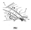
- FIG. 1 On the figure 1 is partially shown a habitable vehicle 10 having a dashboard 12 disposed in front of a windshield 14 carried by the vehicle structure.
- An amount of windshield 16 extends substantially vertically along the height of the windshield and separates it from the door designated by reference 18.
- the upright 16 is covered with a lining piece 20 according to the invention. This part covers the upright 16 and is distant from the inner surface of the windshield 14.
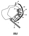
- the upright 16 and the lining piece 20 are shown on a larger scale on the figure 2 .
- a series of clips 22 are clipped onto the upright 16 as known per se.
- These staples comprise elastic retention means capable of gripping connecting tabs 24 disposed on the inner surface of the packing piece 20.
- the lining piece 20 is formed by bi-injection into a mold. It has a rigid main section 26 bordered on one side by a flexible longitudinal lip 28. It further comprises a particularly woven facing sheet 30 forming the visible outer surface of the lining piece and completely covering the rigid section 26 and the lip flexible 28.
- the flexible lip 28 is adapted to be applied without play on the end 19A of bonding of the rabbet 19 of the windshield 14 by deforming elastically.
- the rigid section and the flexible lip are successively molded in the same mold.
- the rigid section 26 is formed, for example, of acrylonitrile-butadiene-styrene (ABS), of polypropylene which may or may not be loaded, for example with ethylene-propylene-dimonomer. (EPDM) and / or talc or glass fibers or any other conventional load.
- ABS acrylonitrile-butadiene-styrene
- EPDM ethylene-propylene-dimonomer
- the flexible lip 28 is made for example of styrene-ethylbutadiene-styrene polymer (SEBS) or ethylene-propylene-dimonomer (EPDM).
- the facing sheet covering the flexible and rigid sections is formed for example of a woven or knitted material, alcantara, thermoplastic olefin (TPO), thermoplastic urethane (TPU), polyvinyl chloride (PVC), a non-woven material for example flocked or a cork sheet or their combination.
- TPO thermoplastic olefin
- TPU thermoplastic urethane
- PVC polyvinyl chloride
- the packing piece has its outer surface in an interface region 31, between the rigid section 26 and the flexible lip 28, a groove 32 extending along the height of the workpiece.
- the facing sheet 30 is deformed recessed according to this crease and matches the shape thereof.
- a tongue 34 extends along its thickness the rigid section 26 and penetrates into a notch of corresponding shape of the flexible lip 28.
- the rigid section or the flexible lip and preferably the rigid section, has retaining profiles 36 allowing the retention during molding as will be explained later.
- These profiles are formed for example of longitudinal ribs projecting from the face opposite to that covered by the facing sheet 30. These profiles are formed on that of the rigid section or the flexible lip which is injected first. In a preferred embodiment, the rigid section is injected first.
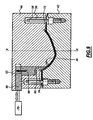
- FIG. 5 On the figure 5 is shown a mold 40 for the injection molding of a vehicle lining piece according to the invention.
- the mold comprises an impression portion 42 and a complementary core portion 44, the parts being movable to slide relative to each other along an axis XX extending perpendicular to the joint plane defined between the imprint portion and the core portion .
- the impression portion has a hollow shape 46 while the core portion has a bulge 48 substantially corresponding to that of the recessed shape 46.
- the bulge 48 and the Deprecated shapes 46 are laterally edged by flat bearing surfaces 50, 52 extending parallel to each other and defining the joint plane of the mold.
- the bulge and the recessed shape delimit between them, when the mold is closed, an injection cavity 54 visible on the figure 7 .
- pins 56 extending parallel to the axis XX project from the fixed part beyond the bearing surfaces 50.
- Bores 58 of corresponding shape are formed opposite in the core portion 44 of the mold to ensure a guide in translation.
- a movable slide 60 called sluice is slidably movable along the axis XX relative to the core portion 44 of the mold.
- This drawer is movable between a retracted position in which it is flush with the surface of the bulge 48 in the cavity 54 and an active position in which it projects relative to the bulge 48 and is applied to the bottom of the recessed form 46 in delimiting in the cavity 54 defined between the recessed form 46 and the bulge 48, two chambers 62, 64 sealingly separated by the slide 60 as shown in FIG. figure 7 .
- the slide 60 is slidably guided in the core portion 44 and has, at its end opposite its active end, a ramp 65 adapted to cooperate with a pusher 66 displaceable with sliding substantially perpendicular to the axis X-X.
- the pusher 66 in the form of a wedge has a complementary ramp 68 forming a cam adapted to cooperate with the ramp 65 to cause the displacement in translation of the slide 60 during the sliding of the pusher 66.
- the pusher 66 is connected to a jack 70 allowing its movement to sliding.
- Each chamber 62, 64 has an injection orifice 72, 74 formed in the core portion 44 of the mold.
- a plurality of injection orifices may be provided in the core portion 44 of the mold.
- the facing sheet 30 is disposed in the open mold between the two parts 42, 44 of the mold.
- this sheet is first cut to size before being introduced into the mold.
- This sheet is applied to the bearing surfaces 50 of the stationary cantilevered portion above the cavity 46 with its face to be visible 30A facing the cavity 46 as illustrated in FIG. figure 6 .
- the mold is then closed as shown on the figure 7 so that the facing sheet is sandwiched between the corresponding bearing surfaces 50, 52.
- the drawer 60 is brought into its active position so that its end presses the facing sheet against the bottom of the recessed form 46 ' pressing on the hidden side 30B thereof.
- the rigid plastic material is then introduced from the injection orifice 72 through the core portion of the mold into the chamber 62 defined by the slide 60.
- the injection is made according to an injection technique chosen from the group consisting, among others, of underwater injection on auxiliary nipple, film injection, underwater injection in curve, and sequential injection. low pressure.
- the plastic is injected on the side 30B of the facing sheet 30 against which the drawer is located as shown in FIG. figure 8 . Under the action of the injected plastic material, the facing sheet is pressed against the bottom of the recessed shape 46 and the plastic material completely fills the chamber 62.
- the drawer 60 After complete filling of this chamber, and before complete cooling of the injected plastic material, the drawer 60 is brought into its retracted position.
- the flexible plastic material is then introduced from the orifice 74 as illustrated on the figure 9 in the chamber 64.
- the material completely fills the chamber 64 and the space left free by the drawer 60 retracted.
- the ribs 36 provide effective retention of the first plastic material injected into the mold preventing it from moving under the action of the second injected plastic material.
- the second plastic material merges with the first plastic material.
- the mold is opened and the packing piece is removed.
- the extensions of the packing sheet are cut along the sections of plastic material.
Landscapes
- Engineering & Computer Science (AREA)
- Manufacturing & Machinery (AREA)
- Mechanical Engineering (AREA)
- Injection Moulding Of Plastics Or The Like (AREA)
- Moulds For Moulding Plastics Or The Like (AREA)
- Vehicle Interior And Exterior Ornaments, Soundproofing, And Insulation (AREA)
Claims (7)
- Verfahren zum Spritzgießen eines Kraftfahrzeug-Ausstattungsteils (20) mittels eines Schleusen-Formwerkzeugs (40), einen ersten und einen zweiten Teil (42, 44) umfassend, untereinander beweglich und dazu bestimmt, mechanisch zusammengefügt zu werden, so dass sie eine Einspritzkavität (54) begrenzen, und wenigstens einen Schieber (60) umfassend, getragen von dem ersten Teil (44), wobei der Schieber selbst in Bezug auf den ersten Teil (44) verschiebbar ist zwischen einer aktiven Position, in der er die Einspritzkavität (54) in eine erste und eine zweite Einspritzkammer (62, 64) unterteilt, und einer inaktiven Position, wo er außerhalb der Kavität (54) versenkt ist, und das Verfahren die Schritte umfasst, die darin bestehen:- einen Verkleidungsbogen (30) in dem offenen Formwerkzeug (40) zu platzieren, zwischen dem ersten und dem zweiten Teil (42, 44) des Formwerkzeugs, wobei eine erste Seite (30B) des Bogens dem ersten Teil (44) des Formwerkzeugs zugewandt ist und eine zweite Seite (30A) des Verkleidungsbogens dem zweiten Teil (42) des Formwerkzeugs zugewandt ist;- das Formwerkzeug auf dem Verkleidungsbogen (30) zu schließen, wobei der Schieber (60) sich in der aktiven Position befindet, so dass er sich auf abdichtende Weise auf der ersten Seite (30B) des Verkleidungsbogens (30) abstützt;- eine erste Einspritzung eines ersten Kunststoffs in die erste Einspritzkammer (62) vorzunehmen, abgegrenzt durch die erste Seite (30B) des Verkleidungsbogens (30) und durch den Schieber (60) des ersten Teils (44), wobei der Schieber (60) seine abdichtende Abstützung auf der ersten Seite (30B) des Verkleidungsbogens (30) beibehält;- den beweglichen Schieber (60) bei geschlossenem Formwerkzeug in die Versenkungsposition zu verschieben;- eine zweite Einspritzung eines zweiten Kunststoffs in die zweite Einspritzkammer (64) - abgegrenzt durch die erste Seite (30B) des Verkleidungsbogens (30) und durch den ersten Teil (44) - vorzunehmen, wobei sich der zweite Kunststoff mit dem ersten Kunststoff vereinigt; und- das Formwerkzeug zu öffnen und das Ausstattungsteil zu entnehmen,dadurch gekennzeichnet, dass der erste Stoff ausgewählt wird aus der Gruppe, die AcrylnitrilButadien-Styrol (ABS) und EPDM-haltiges Propylen umfasst und gemäß einer Spritztechnik gespritzt wird, die aus der Gruppe ausgewählt wird, die den Tunnelanguss mit Hilfszapfen, den Filmanguss, den gebogenen Tunnelanguss und das Niederdruck-Reihenspritzgießverfahren umfasst, und der zweite Stoff ausgewählt wird aus der Gruppe, die Styrol-Buthadien-Styrol (SEBS) und Ethyl-Propylen-Dien-Kautschuk umfasst und mittels gebogenem Tunnelanguß gespritzt wird.
- Spritzgießverfahren nach Anspruch 1, dadurch gekennzeichnet, dass der Verkleidungsbogen (30) verformbar ist und unter der Wirkung des ersten oder des zweiten eingespitzten Kunststoffs gegen den Boden der Einspritzkavität (54) des Formwerkzeugs (40) gepresst wird.
- Spritzgießverfahren nach dem Anspruch 1 oder 2, dadurch gekennzeichnet, dass es einen der Platzierung des Verkleidungsbogens (30) vorausgehenden Schritt umfasst, darin bestehend, den Verkleidungsbogen in einer dem Ausstattungsteil angepassten Form zuzuschneiden.
- Spritzgießverfahren nach einem der Ansprüche 1 bis 3, dadurch gekennzeichnet, dass es einen auf die Entnahme des Teils folgenden Schritt umfasst, darin bestehend, den Überstand des Verkleidungsbogens (30) wegzuschneiden.
- Spritzgießverfahren nach einem der vorhergehenden Ansprüche, dadurch gekennzeichnet, dass der Schritt zum Verschieben des Schiebers (60) aus seiner aktiven Position in seine versenkte Position darin besteht,- einen Zylinder (70), verbunden mit einem einen Nocken bzw. eine Nockenfläche (68) aufweisenden keilförmigen Drücker (66), in einer ersten Richtung zu betätigen;- den Schieber (60) unter der Wirkung der Bewegung des Drückers (66) translatorisch in einer zweiten Richtung zu führen;- den Schieber (60), der eine unter der Wirkung der Bewegung des Drückers (66) mit der Nockenfläche (68) kooperierenden Gegennockenfläche (65) umfasst, in die zweite Richtung zu verschieben.
- Verfahren nach einem der vorhergehenden Ansprüche, dadurch gekennzeichnet, dass der Verkleidungsbogen (30) ausgewählt wird aus der Gruppe, die umfasst: ein gewebtes oder gestricktes Material, aus Alcantara, aus TPO, aus TPU, aus PVC, aus einem nichtgewebten zum Beispiel geflockten Material oder einem Korkblatt und Kombinationen mit einem oder mehreren der vorhergehenden Materialien.
- Ausstattungsteil (20), bestimmt zur Innenverkleidung eines Kraftfahrzeugs, dadurch gekennzeichnet, dass es nach einem der Ansprüche 1 bis 6 realisiert wird.
Applications Claiming Priority (1)
| Application Number | Priority Date | Filing Date | Title |
|---|---|---|---|
| FR0512776A FR2894864B1 (fr) | 2005-12-15 | 2005-12-15 | Procede de moulage par injection plastique d'une piece de garnissage, et piece de garnissage issue de ce procede |
Publications (4)
| Publication Number | Publication Date |
|---|---|
| EP1798112A2 EP1798112A2 (de) | 2007-06-20 |
| EP1798112A3 EP1798112A3 (de) | 2007-09-12 |
| EP1798112A9 EP1798112A9 (de) | 2011-02-23 |
| EP1798112B1 true EP1798112B1 (de) | 2011-05-11 |
Family
ID=36969486
Family Applications (1)
| Application Number | Title | Priority Date | Filing Date |
|---|---|---|---|
| EP06291931A Ceased EP1798112B1 (de) | 2005-12-15 | 2006-12-14 | Verfahren zum Spritzgiessen eines Ausstattungsteiles sowie danach hergestelltes Ausstattungsteil |
Country Status (3)
| Country | Link |
|---|---|
| EP (1) | EP1798112B1 (de) |
| AT (1) | ATE508907T1 (de) |
| FR (1) | FR2894864B1 (de) |
Cited By (1)
| Publication number | Priority date | Publication date | Assignee | Title |
|---|---|---|---|---|
| WO2025172231A1 (fr) | 2024-02-16 | 2025-08-21 | Renault S.A.S. | Procédé de fabrication d'une pièce moulée comprenant une couche décorative |
Families Citing this family (3)
| Publication number | Priority date | Publication date | Assignee | Title |
|---|---|---|---|---|
| JP5633912B2 (ja) * | 2013-08-12 | 2014-12-03 | 三甲株式会社 | 搬送容器の壁構造 |
| US10414348B2 (en) * | 2016-11-04 | 2019-09-17 | Ford Global Technologies Llc | Anti-rocking bracket for vehicle pillar trim |
| DE102021127659A1 (de) * | 2021-10-25 | 2023-04-27 | Hib Trim Part Solutions Gmbh | Verfahren zur Herstellung eines Zierteils, Spritzgusswerkzeug zur Herstellung eines Zierteils sowie Zierteil |
Family Cites Families (12)
| Publication number | Priority date | Publication date | Assignee | Title |
|---|---|---|---|---|
| JPS59109332A (ja) * | 1982-12-15 | 1984-06-25 | Yoshida Kogyo Kk <Ykk> | 合成樹脂製容器の成形方法 |
| JPS61108519A (ja) * | 1984-11-02 | 1986-05-27 | Yoshida Kogyo Kk <Ykk> | 合成樹脂多色成形品の成形方法並びに成形装置及びその成形品 |
| JP3032242B2 (ja) * | 1990-05-25 | 2000-04-10 | 日産自動車株式会社 | インストパッドとフロントピラーガーニッシュの合わせ構造 |
| WO1997012732A1 (en) * | 1995-10-05 | 1997-04-10 | Kellogg Brush Manufacturing Co. | Utensil handle and method of making same |
| JPH10250519A (ja) * | 1997-03-17 | 1998-09-22 | Toyota Motor Corp | エアバッグドア部を一体に有するインストルメントパネル及びその成形方法 |
| JPH1178752A (ja) * | 1997-09-04 | 1999-03-23 | Toyota Motor Corp | エアバッグドア部を一体に有するインストルメントパネル及びその製造方法 |
| DE19745122A1 (de) * | 1997-10-13 | 1999-04-15 | Daimler Chrysler Ag | Verfahren zum Herstellen eines Kunststoff-Verbundteils und Kunststoff-Verbundteil |
| JP3722635B2 (ja) * | 1999-01-21 | 2005-11-30 | 西川化成株式会社 | 射出成形品の製造方法 |
| JP4098447B2 (ja) * | 1999-09-09 | 2008-06-11 | クミ化成株式会社 | 加飾成形方法 |
| JP2001114032A (ja) * | 1999-10-15 | 2001-04-24 | T S Tec Kk | 車両用内装ピラーガーニッシュ |
| JP3910412B2 (ja) * | 2001-11-13 | 2007-04-25 | 関東自動車工業株式会社 | 自動車のエアバッグドア及びその製造方法 |
| DE10306393A1 (de) * | 2003-02-15 | 2004-08-26 | Volkswagen Ag | Bauteilanordnung mit einem Kunststoffbauteil und einem weiteren Bauteil |
-
2005
- 2005-12-15 FR FR0512776A patent/FR2894864B1/fr not_active Expired - Fee Related
-
2006
- 2006-12-14 EP EP06291931A patent/EP1798112B1/de not_active Ceased
- 2006-12-14 AT AT06291931T patent/ATE508907T1/de not_active IP Right Cessation
Cited By (2)
| Publication number | Priority date | Publication date | Assignee | Title |
|---|---|---|---|---|
| WO2025172231A1 (fr) | 2024-02-16 | 2025-08-21 | Renault S.A.S. | Procédé de fabrication d'une pièce moulée comprenant une couche décorative |
| FR3159342A1 (fr) | 2024-02-16 | 2025-08-22 | Renault Sas | Procédé de fabrication d’une pièce moulée comprenant une couche décorative |
Also Published As
| Publication number | Publication date |
|---|---|
| ATE508907T1 (de) | 2011-05-15 |
| FR2894864B1 (fr) | 2010-01-22 |
| EP1798112A3 (de) | 2007-09-12 |
| EP1798112A2 (de) | 2007-06-20 |
| EP1798112A9 (de) | 2011-02-23 |
| FR2894864A1 (fr) | 2007-06-22 |
Similar Documents
| Publication | Publication Date | Title |
|---|---|---|
| US20090025300A1 (en) | Outer belt polypropylene encap insert function partially as material mold tooling shut-off | |
| EP2674274B1 (de) | Verpackungselement und Verfahren zu seiner Herstellung | |
| EP2749390A1 (de) | Einsatzelement, das ein Dekorelement umfasst, das mindestens teilweise mit einer Plastikfolie überzogen ist, und Verfahren zu seiner Herstellung | |
| EP1755924B1 (de) | Innenausstattung eines kraftfahrzeugs und herstellungsverfahren dafür | |
| EP1120303B1 (de) | Kraftfahrzeugsflügel aus Kunststoff und Fahrzeug mit solchem Flügel | |
| EP0589116B1 (de) | Verfahren zum Herstellen eines mehrschichtigen Gegenstandes durch Formen, so hergestellter Gegenstand und Verwendung zur Herstellung von Armaturenbrettern und/oder Verkleidungselementen einer Fahrzeugkarosserie | |
| EP1798112B1 (de) | Verfahren zum Spritzgiessen eines Ausstattungsteiles sowie danach hergestelltes Ausstattungsteil | |
| US20080237925A1 (en) | Vehicle Component and Method For Making a Vehicle Component | |
| EP1292440B1 (de) | Verfahren zur beschichtung und entsprechender gegenstand | |
| EP0094268B1 (de) | Verfahren zum Herstellen von Kunststoffteilen überzogen mit einem Gewebe oder einem anderen flexibelen Überzugsmaterial durch Spritzgiessen und Vorrichtung zur Durchführung dieses Verfahrens | |
| FR2785244A1 (fr) | Procede d'obtention d'une piece d'equipement interieur de vehicule et piece obtenue | |
| US20100260980A1 (en) | Method for producing a molded part comprising different decorative zones | |
| FR2730185A1 (fr) | Procede de realisation de pieces composites en matiere plastique comportant un revetement de surface, moules pour sa mise en oeuvre et pieces composites ainsi obtenues | |
| WO2021122485A1 (fr) | Hayon de véhicule automobile | |
| EP4227061B1 (de) | Verfahren zur herstellung eines fahrzeuginnenverkleidungsteils und innenverkleidungsteil | |
| EP4402001B1 (de) | Einteiliger abdeckstreifen und zusammenbauverfahren | |
| EP0954426A1 (de) | Verfahren zum einfügen von dekorationen in einem thermoplastischen teil | |
| FR2952598A1 (fr) | Procede de fabrication d'un element d'habillage de vehicule automobile et element d'habillage associe | |
| FR2937276A1 (fr) | Procede de fabrication d'une planche de bord comportant un element de decoration et planche de bord obtenue par ce procede | |
| FR3096291A1 (fr) | Procédé de fabrication d’une pièce tridimensionnelle composite et pièce obtenue | |
| FR3072341A1 (fr) | Piece d'equipement interieur d'un vehicule et procede de fabrication associe | |
| FR2937273A1 (fr) | Procede de fabrication d'une planche de bord comportant un element de decoration, insert et planche de bord associes | |
| FR2864923A1 (fr) | Procede de fabrication d'une piece de parement en matiere plastique | |
| FR2907400A1 (fr) | Procede de fabrication d'un habillage interieur de masquage d'un coussin gonflage de securite pour vehicule automobile, et habillage interieur et vehicule automobile correspondant | |
| FR2768373A1 (fr) | Pare-soleil avec un accessoire renforce |
Legal Events
| Date | Code | Title | Description |
|---|---|---|---|
| PUAI | Public reference made under article 153(3) epc to a published international application that has entered the european phase |
Free format text: ORIGINAL CODE: 0009012 |
|
| AK | Designated contracting states |
Kind code of ref document: A2 Designated state(s): AT BE BG CH CY CZ DE DK EE ES FI FR GB GR HU IE IS IT LI LT LU LV MC NL PL PT RO SE SI SK TR |
|
| AX | Request for extension of the european patent |
Extension state: AL BA HR MK YU |
|
| PUAL | Search report despatched |
Free format text: ORIGINAL CODE: 0009013 |
|
| AK | Designated contracting states |
Kind code of ref document: A3 Designated state(s): AT BE BG CH CY CZ DE DK EE ES FI FR GB GR HU IE IS IT LI LT LU LV MC NL PL PT RO SE SI SK TR |
|
| AX | Request for extension of the european patent |
Extension state: AL BA HR MK YU |
|
| 17P | Request for examination filed |
Effective date: 20080220 |
|
| 17Q | First examination report despatched |
Effective date: 20080320 |
|
| AKX | Designation fees paid |
Designated state(s): AT BE BG CH CY CZ DE DK EE ES FI FR GB GR HU IE IS IT LI LT LU LV MC NL PL PT RO SE SI SK TR |
|
| GRAP | Despatch of communication of intention to grant a patent |
Free format text: ORIGINAL CODE: EPIDOSNIGR1 |
|
| RAP1 | Party data changed (applicant data changed or rights of an application transferred) |
Owner name: PEUGEOT CITROEN AUTOMOBILES S.A. Owner name: SIMOLDES PLASTICOS, LDA |
|
| GRAS | Grant fee paid |
Free format text: ORIGINAL CODE: EPIDOSNIGR3 |
|
| GRAA | (expected) grant |
Free format text: ORIGINAL CODE: 0009210 |
|
| AK | Designated contracting states |
Kind code of ref document: B1 Designated state(s): AT BE BG CH CY CZ DE DK EE ES FI FR GB GR HU IE IS IT LI LT LU LV MC NL PL PT RO SE SI SK TR |
|
| REG | Reference to a national code |
Ref country code: GB Ref legal event code: FG4D Free format text: NOT ENGLISH |
|
| REG | Reference to a national code |
Ref country code: CH Ref legal event code: EP |
|
| REG | Reference to a national code |
Ref country code: IE Ref legal event code: FG4D |
|
| REG | Reference to a national code |
Ref country code: DE Ref legal event code: R096 Ref document number: 602006021847 Country of ref document: DE Effective date: 20110622 |
|
| REG | Reference to a national code |
Ref country code: NL Ref legal event code: VDEP Effective date: 20110511 |
|
| PG25 | Lapsed in a contracting state [announced via postgrant information from national office to epo] |
Ref country code: PT Free format text: LAPSE BECAUSE OF FAILURE TO SUBMIT A TRANSLATION OF THE DESCRIPTION OR TO PAY THE FEE WITHIN THE PRESCRIBED TIME-LIMIT Effective date: 20110912 Ref country code: SE Free format text: LAPSE BECAUSE OF FAILURE TO SUBMIT A TRANSLATION OF THE DESCRIPTION OR TO PAY THE FEE WITHIN THE PRESCRIBED TIME-LIMIT Effective date: 20110511 Ref country code: LT Free format text: LAPSE BECAUSE OF FAILURE TO SUBMIT A TRANSLATION OF THE DESCRIPTION OR TO PAY THE FEE WITHIN THE PRESCRIBED TIME-LIMIT Effective date: 20110511 |
|
| PG25 | Lapsed in a contracting state [announced via postgrant information from national office to epo] |
Ref country code: ES Free format text: LAPSE BECAUSE OF FAILURE TO SUBMIT A TRANSLATION OF THE DESCRIPTION OR TO PAY THE FEE WITHIN THE PRESCRIBED TIME-LIMIT Effective date: 20110822 Ref country code: SI Free format text: LAPSE BECAUSE OF FAILURE TO SUBMIT A TRANSLATION OF THE DESCRIPTION OR TO PAY THE FEE WITHIN THE PRESCRIBED TIME-LIMIT Effective date: 20110511 Ref country code: LV Free format text: LAPSE BECAUSE OF FAILURE TO SUBMIT A TRANSLATION OF THE DESCRIPTION OR TO PAY THE FEE WITHIN THE PRESCRIBED TIME-LIMIT Effective date: 20110511 Ref country code: AT Free format text: LAPSE BECAUSE OF FAILURE TO SUBMIT A TRANSLATION OF THE DESCRIPTION OR TO PAY THE FEE WITHIN THE PRESCRIBED TIME-LIMIT Effective date: 20110511 Ref country code: CY Free format text: LAPSE BECAUSE OF FAILURE TO SUBMIT A TRANSLATION OF THE DESCRIPTION OR TO PAY THE FEE WITHIN THE PRESCRIBED TIME-LIMIT Effective date: 20110511 Ref country code: FI Free format text: LAPSE BECAUSE OF FAILURE TO SUBMIT A TRANSLATION OF THE DESCRIPTION OR TO PAY THE FEE WITHIN THE PRESCRIBED TIME-LIMIT Effective date: 20110511 Ref country code: IS Free format text: LAPSE BECAUSE OF FAILURE TO SUBMIT A TRANSLATION OF THE DESCRIPTION OR TO PAY THE FEE WITHIN THE PRESCRIBED TIME-LIMIT Effective date: 20110911 |
|
| REG | Reference to a national code |
Ref country code: IE Ref legal event code: FD4D |
|
| PG25 | Lapsed in a contracting state [announced via postgrant information from national office to epo] |
Ref country code: NL Free format text: LAPSE BECAUSE OF FAILURE TO SUBMIT A TRANSLATION OF THE DESCRIPTION OR TO PAY THE FEE WITHIN THE PRESCRIBED TIME-LIMIT Effective date: 20110511 |
|
| PG25 | Lapsed in a contracting state [announced via postgrant information from national office to epo] |
Ref country code: IE Free format text: LAPSE BECAUSE OF FAILURE TO SUBMIT A TRANSLATION OF THE DESCRIPTION OR TO PAY THE FEE WITHIN THE PRESCRIBED TIME-LIMIT Effective date: 20110511 Ref country code: EE Free format text: LAPSE BECAUSE OF FAILURE TO SUBMIT A TRANSLATION OF THE DESCRIPTION OR TO PAY THE FEE WITHIN THE PRESCRIBED TIME-LIMIT Effective date: 20110511 Ref country code: CZ Free format text: LAPSE BECAUSE OF FAILURE TO SUBMIT A TRANSLATION OF THE DESCRIPTION OR TO PAY THE FEE WITHIN THE PRESCRIBED TIME-LIMIT Effective date: 20110511 |
|
| PGFP | Annual fee paid to national office [announced via postgrant information from national office to epo] |
Ref country code: IE Payment date: 20111111 Year of fee payment: 6 |
|
| PG25 | Lapsed in a contracting state [announced via postgrant information from national office to epo] |
Ref country code: DK Free format text: LAPSE BECAUSE OF FAILURE TO SUBMIT A TRANSLATION OF THE DESCRIPTION OR TO PAY THE FEE WITHIN THE PRESCRIBED TIME-LIMIT Effective date: 20110511 Ref country code: RO Free format text: LAPSE BECAUSE OF FAILURE TO SUBMIT A TRANSLATION OF THE DESCRIPTION OR TO PAY THE FEE WITHIN THE PRESCRIBED TIME-LIMIT Effective date: 20110511 Ref country code: PL Free format text: LAPSE BECAUSE OF FAILURE TO SUBMIT A TRANSLATION OF THE DESCRIPTION OR TO PAY THE FEE WITHIN THE PRESCRIBED TIME-LIMIT Effective date: 20110511 Ref country code: SK Free format text: LAPSE BECAUSE OF FAILURE TO SUBMIT A TRANSLATION OF THE DESCRIPTION OR TO PAY THE FEE WITHIN THE PRESCRIBED TIME-LIMIT Effective date: 20110511 |
|
| PLBE | No opposition filed within time limit |
Free format text: ORIGINAL CODE: 0009261 |
|
| STAA | Information on the status of an ep patent application or granted ep patent |
Free format text: STATUS: NO OPPOSITION FILED WITHIN TIME LIMIT |
|
| 26N | No opposition filed |
Effective date: 20120214 |
|
| PG25 | Lapsed in a contracting state [announced via postgrant information from national office to epo] |
Ref country code: IT Free format text: LAPSE BECAUSE OF FAILURE TO SUBMIT A TRANSLATION OF THE DESCRIPTION OR TO PAY THE FEE WITHIN THE PRESCRIBED TIME-LIMIT Effective date: 20110511 |
|
| REG | Reference to a national code |
Ref country code: DE Ref legal event code: R097 Ref document number: 602006021847 Country of ref document: DE Effective date: 20120214 |
|
| BERE | Be: lapsed |
Owner name: PEUGEOT CITROEN AUTOMOBILES S.A. Effective date: 20111231 Owner name: SIMOLDES PLASTICOS, LDA Effective date: 20111231 |
|
| PG25 | Lapsed in a contracting state [announced via postgrant information from national office to epo] |
Ref country code: MC Free format text: LAPSE BECAUSE OF NON-PAYMENT OF DUE FEES Effective date: 20111231 |
|
| REG | Reference to a national code |
Ref country code: CH Ref legal event code: PL |
|
| PG25 | Lapsed in a contracting state [announced via postgrant information from national office to epo] |
Ref country code: BE Free format text: LAPSE BECAUSE OF NON-PAYMENT OF DUE FEES Effective date: 20111231 Ref country code: CH Free format text: LAPSE BECAUSE OF NON-PAYMENT OF DUE FEES Effective date: 20111231 Ref country code: LI Free format text: LAPSE BECAUSE OF NON-PAYMENT OF DUE FEES Effective date: 20111231 |
|
| PG25 | Lapsed in a contracting state [announced via postgrant information from national office to epo] |
Ref country code: LU Free format text: LAPSE BECAUSE OF NON-PAYMENT OF DUE FEES Effective date: 20111214 |
|
| PG25 | Lapsed in a contracting state [announced via postgrant information from national office to epo] |
Ref country code: BG Free format text: LAPSE BECAUSE OF FAILURE TO SUBMIT A TRANSLATION OF THE DESCRIPTION OR TO PAY THE FEE WITHIN THE PRESCRIBED TIME-LIMIT Effective date: 20110811 |
|
| PG25 | Lapsed in a contracting state [announced via postgrant information from national office to epo] |
Ref country code: TR Free format text: LAPSE BECAUSE OF FAILURE TO SUBMIT A TRANSLATION OF THE DESCRIPTION OR TO PAY THE FEE WITHIN THE PRESCRIBED TIME-LIMIT Effective date: 20110511 |
|
| PG25 | Lapsed in a contracting state [announced via postgrant information from national office to epo] |
Ref country code: HU Free format text: LAPSE BECAUSE OF FAILURE TO SUBMIT A TRANSLATION OF THE DESCRIPTION OR TO PAY THE FEE WITHIN THE PRESCRIBED TIME-LIMIT Effective date: 20110511 |
|
| PG25 | Lapsed in a contracting state [announced via postgrant information from national office to epo] |
Ref country code: GR Free format text: LAPSE BECAUSE OF FAILURE TO SUBMIT A TRANSLATION OF THE DESCRIPTION OR TO PAY THE FEE WITHIN THE PRESCRIBED TIME-LIMIT Effective date: 20110511 |
|
| PGFP | Annual fee paid to national office [announced via postgrant information from national office to epo] |
Ref country code: GB Payment date: 20141218 Year of fee payment: 9 |
|
| PGFP | Annual fee paid to national office [announced via postgrant information from national office to epo] |
Ref country code: DE Payment date: 20141211 Year of fee payment: 9 |
|
| PG25 | Lapsed in a contracting state [announced via postgrant information from national office to epo] |
Ref country code: IE Free format text: LAPSE BECAUSE OF FAILURE TO SUBMIT A TRANSLATION OF THE DESCRIPTION OR TO PAY THE FEE WITHIN THE PRESCRIBED TIME-LIMIT Effective date: 20111118 |
|
| REG | Reference to a national code |
Ref country code: FR Ref legal event code: PLFP Year of fee payment: 10 |
|
| REG | Reference to a national code |
Ref country code: DE Ref legal event code: R119 Ref document number: 602006021847 Country of ref document: DE |
|
| GBPC | Gb: european patent ceased through non-payment of renewal fee |
Effective date: 20151214 |
|
| PG25 | Lapsed in a contracting state [announced via postgrant information from national office to epo] |
Ref country code: DE Free format text: LAPSE BECAUSE OF NON-PAYMENT OF DUE FEES Effective date: 20160701 Ref country code: GB Free format text: LAPSE BECAUSE OF NON-PAYMENT OF DUE FEES Effective date: 20151214 |
|
| REG | Reference to a national code |
Ref country code: FR Ref legal event code: PLFP Year of fee payment: 11 |
|
| REG | Reference to a national code |
Ref country code: FR Ref legal event code: PLFP Year of fee payment: 12 |
|
| PGFP | Annual fee paid to national office [announced via postgrant information from national office to epo] |
Ref country code: FR Payment date: 20211209 Year of fee payment: 16 |
|
| PG25 | Lapsed in a contracting state [announced via postgrant information from national office to epo] |
Ref country code: FR Free format text: LAPSE BECAUSE OF NON-PAYMENT OF DUE FEES Effective date: 20221231 |