EP1798112B1 - Method of moulding a trim part by plastic injection, and trim part resulting from this method - Google Patents
Method of moulding a trim part by plastic injection, and trim part resulting from this method Download PDFInfo
- Publication number
- EP1798112B1 EP1798112B1 EP06291931A EP06291931A EP1798112B1 EP 1798112 B1 EP1798112 B1 EP 1798112B1 EP 06291931 A EP06291931 A EP 06291931A EP 06291931 A EP06291931 A EP 06291931A EP 1798112 B1 EP1798112 B1 EP 1798112B1
- Authority
- EP
- European Patent Office
- Prior art keywords
- injection
- mould
- slide
- facing sheet
- plastic
- Prior art date
- Legal status (The legal status is an assumption and is not a legal conclusion. Google has not performed a legal analysis and makes no representation as to the accuracy of the status listed.)
- Not-in-force
Links
- 238000002347 injection Methods 0.000 title claims abstract description 33
- 239000007924 injection Substances 0.000 title claims abstract description 33
- 229920003023 plastic Polymers 0.000 title claims abstract description 23
- 239000004033 plastic Substances 0.000 title claims abstract description 23
- 238000000034 method Methods 0.000 title claims abstract description 18
- 238000000465 moulding Methods 0.000 title description 4
- 239000000463 material Substances 0.000 claims abstract description 28
- 238000001746 injection moulding Methods 0.000 claims description 7
- 229920002397 thermoplastic olefin Polymers 0.000 claims description 4
- 229920002803 thermoplastic polyurethane Polymers 0.000 claims description 4
- 238000009966 trimming Methods 0.000 claims description 4
- YPNCHMZOZQTUKD-UHFFFAOYSA-N C=CC1=CC=CC=C1.C(C)C=CC=C.C=CC1=CC=CC=C1 Chemical compound C=CC1=CC=CC=C1.C(C)C=CC=C.C=CC1=CC=CC=C1 YPNCHMZOZQTUKD-UHFFFAOYSA-N 0.000 claims description 2
- 239000004743 Polypropylene Substances 0.000 claims description 2
- 239000004676 acrylonitrile butadiene styrene Substances 0.000 claims description 2
- 239000007799 cork Substances 0.000 claims description 2
- -1 polypropylene Polymers 0.000 claims description 2
- 229920001155 polypropylene Polymers 0.000 claims description 2
- 239000004800 polyvinyl chloride Substances 0.000 claims description 2
- 238000010137 moulding (plastic) Methods 0.000 claims 3
- 230000003213 activating effect Effects 0.000 claims 1
- 238000000605 extraction Methods 0.000 claims 1
- MTAZNLWOLGHBHU-UHFFFAOYSA-N butadiene-styrene rubber Chemical compound C=CC=C.C=CC1=CC=CC=C1 MTAZNLWOLGHBHU-UHFFFAOYSA-N 0.000 abstract 1
- 238000012856 packing Methods 0.000 description 8
- 230000014759 maintenance of location Effects 0.000 description 3
- 230000000295 complement effect Effects 0.000 description 2
- 238000001816 cooling Methods 0.000 description 2
- 238000004519 manufacturing process Methods 0.000 description 2
- 239000002184 metal Substances 0.000 description 2
- 238000004026 adhesive bonding Methods 0.000 description 1
- 235000021028 berry Nutrition 0.000 description 1
- 230000015572 biosynthetic process Effects 0.000 description 1
- 238000006073 displacement reaction Methods 0.000 description 1
- 239000013013 elastic material Substances 0.000 description 1
- 239000004744 fabric Substances 0.000 description 1
- 229920002457 flexible plastic Polymers 0.000 description 1
- 239000003365 glass fiber Substances 0.000 description 1
- 239000002991 molded plastic Substances 0.000 description 1
- 210000002445 nipple Anatomy 0.000 description 1
- 229920000642 polymer Polymers 0.000 description 1
- 238000003825 pressing Methods 0.000 description 1
- 229920003002 synthetic resin Polymers 0.000 description 1
- 239000000057 synthetic resin Substances 0.000 description 1
- 239000000454 talc Substances 0.000 description 1
- 229910052623 talc Inorganic materials 0.000 description 1
- 230000000007 visual effect Effects 0.000 description 1
Images


Classifications
-
- B—PERFORMING OPERATIONS; TRANSPORTING
- B29—WORKING OF PLASTICS; WORKING OF SUBSTANCES IN A PLASTIC STATE IN GENERAL
- B29C—SHAPING OR JOINING OF PLASTICS; SHAPING OF MATERIAL IN A PLASTIC STATE, NOT OTHERWISE PROVIDED FOR; AFTER-TREATMENT OF THE SHAPED PRODUCTS, e.g. REPAIRING
- B29C45/00—Injection moulding, i.e. forcing the required volume of moulding material through a nozzle into a closed mould; Apparatus therefor
- B29C45/16—Making multilayered or multicoloured articles
- B29C45/1671—Making multilayered or multicoloured articles with an insert
-
- B—PERFORMING OPERATIONS; TRANSPORTING
- B29—WORKING OF PLASTICS; WORKING OF SUBSTANCES IN A PLASTIC STATE IN GENERAL
- B29C—SHAPING OR JOINING OF PLASTICS; SHAPING OF MATERIAL IN A PLASTIC STATE, NOT OTHERWISE PROVIDED FOR; AFTER-TREATMENT OF THE SHAPED PRODUCTS, e.g. REPAIRING
- B29C45/00—Injection moulding, i.e. forcing the required volume of moulding material through a nozzle into a closed mould; Apparatus therefor
- B29C45/16—Making multilayered or multicoloured articles
- B29C2045/1687—Making multilayered or multicoloured articles preventing leakage of second injected material from the mould cavity
-
- B—PERFORMING OPERATIONS; TRANSPORTING
- B29—WORKING OF PLASTICS; WORKING OF SUBSTANCES IN A PLASTIC STATE IN GENERAL
- B29C—SHAPING OR JOINING OF PLASTICS; SHAPING OF MATERIAL IN A PLASTIC STATE, NOT OTHERWISE PROVIDED FOR; AFTER-TREATMENT OF THE SHAPED PRODUCTS, e.g. REPAIRING
- B29C45/00—Injection moulding, i.e. forcing the required volume of moulding material through a nozzle into a closed mould; Apparatus therefor
- B29C45/16—Making multilayered or multicoloured articles
- B29C45/1635—Making multilayered or multicoloured articles using displaceable mould parts, e.g. retractable partition between adjacent mould cavities
- B29C45/1639—Removable partitions between adjacent mould cavity portions
-
- B—PERFORMING OPERATIONS; TRANSPORTING
- B29—WORKING OF PLASTICS; WORKING OF SUBSTANCES IN A PLASTIC STATE IN GENERAL
- B29C—SHAPING OR JOINING OF PLASTICS; SHAPING OF MATERIAL IN A PLASTIC STATE, NOT OTHERWISE PROVIDED FOR; AFTER-TREATMENT OF THE SHAPED PRODUCTS, e.g. REPAIRING
- B29C45/00—Injection moulding, i.e. forcing the required volume of moulding material through a nozzle into a closed mould; Apparatus therefor
- B29C45/16—Making multilayered or multicoloured articles
- B29C45/1676—Making multilayered or multicoloured articles using a soft material and a rigid material, e.g. making articles with a sealing part
-
- B—PERFORMING OPERATIONS; TRANSPORTING
- B29—WORKING OF PLASTICS; WORKING OF SUBSTANCES IN A PLASTIC STATE IN GENERAL
- B29L—INDEXING SCHEME ASSOCIATED WITH SUBCLASS B29C, RELATING TO PARTICULAR ARTICLES
- B29L2031/00—Other particular articles
- B29L2031/30—Vehicles, e.g. ships or aircraft, or body parts thereof
- B29L2031/3005—Body finishings
-
- B—PERFORMING OPERATIONS; TRANSPORTING
- B60—VEHICLES IN GENERAL
- B60R—VEHICLES, VEHICLE FITTINGS, OR VEHICLE PARTS, NOT OTHERWISE PROVIDED FOR
- B60R13/00—Elements for body-finishing, identifying, or decorating; Arrangements or adaptations for advertising purposes
- B60R13/02—Internal Trim mouldings ; Internal Ledges; Wall liners for passenger compartments; Roof liners
- B60R13/0206—Arrangements of fasteners and clips specially adapted for attaching inner vehicle liners or mouldings
Definitions
- the present invention relates to a plastic injection molding process of a motor vehicle facing part such as a bay window jamb trim.
- the windows including the windshield, are maintained in a metal frame of the vehicle structure.
- the amounts of berry frames of some known vehicles are covered with siding linings. These fittings completely cover the metal frame and can be supported along a longitudinal edge directly on the windshield.
- the lining comprises a rigid main section made of molded plastic material along an edge of which is formed a longitudinal lip made of an elastic material. This longitudinal lip is adapted to be applied on the end of the gluing of the rabbet windshield thus ensuring a play-free adjustment between the rabbet of the windshield and the lining without the risk of generating unwanted noise.
- the linings have on the side of the cabin a surface covered with fabric.
- linings comprise a lining blank supporting a facing sheet and formed of a rigid material section along which is attached and fixed a piece of grained material, this design generating high manufacturing costs.
- the document JP 2003 146173 A discloses a method of plastic injection molding a packing piece in the field of airbags.
- the JP 2000 patent 210978 also relates to a method of injection molding a piece of packing.
- FR 2 572 676 discloses a method and apparatus for forming multicolored synthetic resin moldings.
- the object of the invention is to provide an injection molding method for forming a vehicle lining part comprising a facing surface and having two sections of different rigidities completely covered by the facing, and which, moreover, is reduced implementation cost.
- the subject of the invention is a method of molding by plastic injection of a vehicle lining part according to claim 1.
- the method comprises one or more of the features described in claims 2 to 6.
- the invention further relates to a lining piece for garnishing the interior of a motor vehicle, made by the method above.
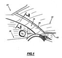
- FIG. 1 On the figure 1 is partially shown a habitable vehicle 10 having a dashboard 12 disposed in front of a windshield 14 carried by the vehicle structure.
- An amount of windshield 16 extends substantially vertically along the height of the windshield and separates it from the door designated by reference 18.
- the upright 16 is covered with a lining piece 20 according to the invention. This part covers the upright 16 and is distant from the inner surface of the windshield 14.
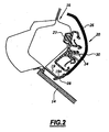
- the upright 16 and the lining piece 20 are shown on a larger scale on the figure 2 .
- a series of clips 22 are clipped onto the upright 16 as known per se.
- These staples comprise elastic retention means capable of gripping connecting tabs 24 disposed on the inner surface of the packing piece 20.
- the lining piece 20 is formed by bi-injection into a mold. It has a rigid main section 26 bordered on one side by a flexible longitudinal lip 28. It further comprises a particularly woven facing sheet 30 forming the visible outer surface of the lining piece and completely covering the rigid section 26 and the lip flexible 28.
- the flexible lip 28 is adapted to be applied without play on the end 19A of bonding of the rabbet 19 of the windshield 14 by deforming elastically.
- the rigid section and the flexible lip are successively molded in the same mold.
- the rigid section 26 is formed, for example, of acrylonitrile-butadiene-styrene (ABS), of polypropylene which may or may not be loaded, for example with ethylene-propylene-dimonomer. (EPDM) and / or talc or glass fibers or any other conventional load.
- ABS acrylonitrile-butadiene-styrene
- EPDM ethylene-propylene-dimonomer
- the flexible lip 28 is made for example of styrene-ethylbutadiene-styrene polymer (SEBS) or ethylene-propylene-dimonomer (EPDM).
- the facing sheet covering the flexible and rigid sections is formed for example of a woven or knitted material, alcantara, thermoplastic olefin (TPO), thermoplastic urethane (TPU), polyvinyl chloride (PVC), a non-woven material for example flocked or a cork sheet or their combination.
- TPO thermoplastic olefin
- TPU thermoplastic urethane
- PVC polyvinyl chloride
- the packing piece has its outer surface in an interface region 31, between the rigid section 26 and the flexible lip 28, a groove 32 extending along the height of the workpiece.
- the facing sheet 30 is deformed recessed according to this crease and matches the shape thereof.
- a tongue 34 extends along its thickness the rigid section 26 and penetrates into a notch of corresponding shape of the flexible lip 28.
- the rigid section or the flexible lip and preferably the rigid section, has retaining profiles 36 allowing the retention during molding as will be explained later.
- These profiles are formed for example of longitudinal ribs projecting from the face opposite to that covered by the facing sheet 30. These profiles are formed on that of the rigid section or the flexible lip which is injected first. In a preferred embodiment, the rigid section is injected first.
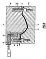
- FIG. 5 On the figure 5 is shown a mold 40 for the injection molding of a vehicle lining piece according to the invention.
- the mold comprises an impression portion 42 and a complementary core portion 44, the parts being movable to slide relative to each other along an axis XX extending perpendicular to the joint plane defined between the imprint portion and the core portion .
- the impression portion has a hollow shape 46 while the core portion has a bulge 48 substantially corresponding to that of the recessed shape 46.
- the bulge 48 and the Deprecated shapes 46 are laterally edged by flat bearing surfaces 50, 52 extending parallel to each other and defining the joint plane of the mold.
- the bulge and the recessed shape delimit between them, when the mold is closed, an injection cavity 54 visible on the figure 7 .
- pins 56 extending parallel to the axis XX project from the fixed part beyond the bearing surfaces 50.
- Bores 58 of corresponding shape are formed opposite in the core portion 44 of the mold to ensure a guide in translation.
- a movable slide 60 called sluice is slidably movable along the axis XX relative to the core portion 44 of the mold.
- This drawer is movable between a retracted position in which it is flush with the surface of the bulge 48 in the cavity 54 and an active position in which it projects relative to the bulge 48 and is applied to the bottom of the recessed form 46 in delimiting in the cavity 54 defined between the recessed form 46 and the bulge 48, two chambers 62, 64 sealingly separated by the slide 60 as shown in FIG. figure 7 .
- the slide 60 is slidably guided in the core portion 44 and has, at its end opposite its active end, a ramp 65 adapted to cooperate with a pusher 66 displaceable with sliding substantially perpendicular to the axis X-X.
- the pusher 66 in the form of a wedge has a complementary ramp 68 forming a cam adapted to cooperate with the ramp 65 to cause the displacement in translation of the slide 60 during the sliding of the pusher 66.
- the pusher 66 is connected to a jack 70 allowing its movement to sliding.
- Each chamber 62, 64 has an injection orifice 72, 74 formed in the core portion 44 of the mold.
- a plurality of injection orifices may be provided in the core portion 44 of the mold.
- the facing sheet 30 is disposed in the open mold between the two parts 42, 44 of the mold.
- this sheet is first cut to size before being introduced into the mold.
- This sheet is applied to the bearing surfaces 50 of the stationary cantilevered portion above the cavity 46 with its face to be visible 30A facing the cavity 46 as illustrated in FIG. figure 6 .
- the mold is then closed as shown on the figure 7 so that the facing sheet is sandwiched between the corresponding bearing surfaces 50, 52.
- the drawer 60 is brought into its active position so that its end presses the facing sheet against the bottom of the recessed form 46 ' pressing on the hidden side 30B thereof.
- the rigid plastic material is then introduced from the injection orifice 72 through the core portion of the mold into the chamber 62 defined by the slide 60.
- the injection is made according to an injection technique chosen from the group consisting, among others, of underwater injection on auxiliary nipple, film injection, underwater injection in curve, and sequential injection. low pressure.
- the plastic is injected on the side 30B of the facing sheet 30 against which the drawer is located as shown in FIG. figure 8 . Under the action of the injected plastic material, the facing sheet is pressed against the bottom of the recessed shape 46 and the plastic material completely fills the chamber 62.
- the drawer 60 After complete filling of this chamber, and before complete cooling of the injected plastic material, the drawer 60 is brought into its retracted position.
- the flexible plastic material is then introduced from the orifice 74 as illustrated on the figure 9 in the chamber 64.
- the material completely fills the chamber 64 and the space left free by the drawer 60 retracted.
- the ribs 36 provide effective retention of the first plastic material injected into the mold preventing it from moving under the action of the second injected plastic material.
- the second plastic material merges with the first plastic material.
- the mold is opened and the packing piece is removed.
- the extensions of the packing sheet are cut along the sections of plastic material.
Abstract
Description
La présente invention concerne un procédé de moulage par injection plastique d'une pièce de parement de véhicule automobile tel qu'une garniture de montant de baie vitrée.The present invention relates to a plastic injection molding process of a motor vehicle facing part such as a bay window jamb trim.
Dans les véhicules automobiles, les baies vitrées, et notamment le pare-brise, sont maintenues dans un cadre métallique de la structure du véhicule. Pour améliorer l'aspect visuel intérieur de l'habitacle, les montants des cadres de baies de certains véhicules connus sont recouverts de garnitures de parement. Ces garnitures recouvrent totalement le cadre métallique et peuvent s'appuyer suivant un bord longitudinal directement sur le pare-brise.In motor vehicles, the windows, including the windshield, are maintained in a metal frame of the vehicle structure. To improve the interior visual appearance of the cabin, the amounts of berry frames of some known vehicles are covered with siding linings. These fittings completely cover the metal frame and can be supported along a longitudinal edge directly on the windshield.
Ces garnitures sont particulièrement importantes pour le style intérieur du véhicule puisqu'elles sont en permanence sous le regard du conducteur et du passager avant. Elles conditionnent aussi la visibilité du conducteur.These trimmings are particularly important for the interior styling of the vehicle since they are constantly under the watch of the driver and front passenger. They also condition the visibility of the driver.
Afin de permettre que la garniture tienne sur le cadre maintenant le pare-brise, la garniture comporte un tronçon principal rigide réalisé en matière plastique moulé suivant un bord duquel est formé une lèvre longitudinale réalisée dans un matériau élastique. Cette lèvre longitudinale est propre à s'appliquer sur l'extrémité du collage de la feuillure du pare-brise assurant ainsi un ajustement sans jeu entre la feuillure du pare-brise et la garniture sans risquer de générer de bruits indésirables.In order to allow the lining to fit on the frame now holding the windshield, the lining comprises a rigid main section made of molded plastic material along an edge of which is formed a longitudinal lip made of an elastic material. This longitudinal lip is adapted to be applied on the end of the gluing of the rabbet windshield thus ensuring a play-free adjustment between the rabbet of the windshield and the lining without the risk of generating unwanted noise.
Par ailleurs, dans les véhicules haut de gamme, il est connu que les garnitures présentent du côté de l'habitacle une surface recouverte de tissu.Furthermore, in high-end vehicles, it is known that the linings have on the side of the cabin a surface covered with fabric.
Cependant, de telles garnitures comportent une ébauche de garniture supportant une feuille de parement et formée d'un tronçon en matériau rigide le long duquel est rapportée et fixée une pièce en matériau d'aspect grainé, cette conception engendrant des coûts de fabrication industrielle élevés.However, such linings comprise a lining blank supporting a facing sheet and formed of a rigid material section along which is attached and fixed a piece of grained material, this design generating high manufacturing costs.
Le document
L'invention a pour but de proposer un procédé de moulage par injection permettant de former une pièce de garnissage de véhicule comportant une surface de parement et présentant deux tronçons de rigidités différentes recouverts complètement par le parement, et qui de surcroît, soit d'un coût de mise en oeuvre réduit.The object of the invention is to provide an injection molding method for forming a vehicle lining part comprising a facing surface and having two sections of different rigidities completely covered by the facing, and which, moreover, is reduced implementation cost.
A cet effet, l'invention a pour objet un procédé de moulage par injection plastique d'une pièce de garnissage de véhicule selon la revendication 1.For this purpose, the subject of the invention is a method of molding by plastic injection of a vehicle lining part according to claim 1.
Suivant des modes particuliers de mise en oeuvre, le procédé comporte une ou plusieurs des caractéristiques décrites dans les revendications 2 à 6.According to particular embodiments, the method comprises one or more of the features described in claims 2 to 6.
L'invention a en outre pour objet une pièce de garnissage, destinée à garnir l'intérieur d'un véhicule automobile, réalisée par le procédé ci-dessus.The invention further relates to a lining piece for garnishing the interior of a motor vehicle, made by the method above.
L'invention sera mieux comprise à la lecture de la description qui va suivre, donnée uniquement à titre d'exemple et faite en se référant aux dessins, sur lesquels :
- la
figure 1 est une vue en perspective partielle d'un habitacle de véhicule automobile montrant un garnissage selon l'invention ; - la
figure 2 est une vue en section d'un montant avant de véhicule automobile montrant un garnissage selon l'invention . - la
figure 3 est une vue à plus grande échelle de l'extrémité inférieure de la pièce de garnissage de lafigure 1 ; - la
figure 4 est une vue en section du garnissage de lafigure 1 prise suivant la ligne II-II ; - la
figure 5 est une vue en section d'un moule en position ouverte pour l'injection d'un garnissage selon l'invention ; et - les
figures 6 ,7 ,8 et9 sont des vues du moule illustrant des phases successives d'injection d'une pièce de garnissage.
- the
figure 1 is a partial perspective view of a passenger compartment of a motor vehicle showing a lining according to the invention; - the
figure 2 is a sectional view of a front pillar of a motor vehicle showing a lining according to the invention. - the
figure 3 is a larger-scale view of the lower end of the packing piece of thefigure 1 ; - the
figure 4 is a sectional view of the packing of thefigure 1 taken along line II-II; - the
figure 5 is a sectional view of a mold in the open position for the injection of a lining according to the invention; and - the
figures 6 ,7 ,8 and9 are views of the mold illustrating successive phases of injection of a lining piece.
Sur la
Le montant 16 et la pièce de garnissage 20 sont représentés à plus grande échelle sur la
Pour le montage de la pièce de garnissage 20 sur le montant 16, une série d'agrafes 22 sont clippées sur le montant 16 comme connu en soi. Ces agrafes comportent des moyens de retenue élastique propres à enserrer des pattes de liaison 24 disposées sur la surface interne de la pièce de garnissage 20.For mounting the
La pièce de garnissage 20 est formée par bi-injection dans un moule. Elle présente un tronçon principal rigide 26 bordé d'un côté par une lèvre longitudinale souple 28. Elle comporte en outre une feuille de parement 30 notamment tissée formant la surface extérieure visible de la pièce de garnissage et recouvrant complètement le tronçon rigide 26 et la lèvre souple 28.The
La lèvre souple 28 est propre à s'appliquer sans jeu sur l'extrémité 19A de collage de la feuillure 19 du pare-brise 14 en se déformant élastiquement.The
Le tronçon rigide et la lèvre souple sont moulés successivement dans un même moule.The rigid section and the flexible lip are successively molded in the same mold.
Le tronçon rigide 26 est formé par exemple d'Acrylonitryle-Butadiène-Styrène (ABS), de polypropylène chargé ou non par exemple d'Ethylène-Propylène-Dimonomère (EPDM) et/ou de talc ou bien de fibres de verre ou encore tout autre charge classique. La lèvre souple 28 est réalisée par exemple en polymère Styrène-Ethylbutadiène-Styrène (SEBS) ou en Ethylène-Propylène-Dimonomère (EPDM).The
La feuille de parement recouvrant les tronçons souple et rigide est formée par exemple d'un matériau tissé ou tricoté, d'alcantara, d'Oléfine Thermoplastique (TPO), d'Uréthane Thermoplastique (TPU), de Polychlorure de vinyle (PVC), d'un matériau non tissé par exemple floqué ou d'une feuille de liège ou de leur combinaison.The facing sheet covering the flexible and rigid sections is formed for example of a woven or knitted material, alcantara, thermoplastic olefin (TPO), thermoplastic urethane (TPU), polyvinyl chloride (PVC), a non-woven material for example flocked or a cork sheet or their combination.
Comme illustré sur les
A l'interface 31 entre le tronçon rigide 26 et la lèvre souple 28, ceux-ci s'interpénètrent suivant l'épaisseur de la pièce de garnissage. Ainsi par exemple, une langue 34 prolonge suivant son épaisseur le tronçon rigide 26 et pénètre dans une encoche de forme correspondante de la lèvre souple 28.At the
Enfin, au voisinage de l'interface 31, le tronçon rigide ou la lèvre souple, et de préférence le tronçon rigide, présente des profils de retenue 36 permettant la retenue lors du moulage comme cela sera expliqué ultérieurement. Ces profils sont formés par exemple de nervures longitudinales faisant saillie sur la face opposée à celle couverte par la feuille de parement 30. Ces profils sont formés sur celui du tronçon rigide ou de la lèvre souple qui est injecté le premier. Dans un mode de réalisation préféré, le tronçon rigide est injecté le premier.Finally, in the vicinity of the
Sur la
Le moule comporte une partie empreinte 42 et une partie noyau complémentaire 44, les parties étant mobiles à coulissement l'une par rapport à l'autre suivant un axe X-X s'étendant perpendiculairement au plan de joint défini entre la partie empreinte et la partie noyau. La partie empreinte présente une forme en creux 46 alors que la partie noyau présente un renflement 48 de forme sensiblement correspondante à celle de la forme en creux 46. Le renflement 48 et la forme en creux 46 sont bordés latéralement par des surfaces d'appui planes 50, 52 s'étendant parallèlement l'une à l'autre et définissant le plan de joint du moule.The mold comprises an
Le renflement et la forme en creux délimitent entre eux, lorsque le moule est fermé, une cavité d'injection 54 visible sur la
Par ailleurs, des broches 56 s'étendant parallèlement à l'axe X-X font saillie depuis la partie fixe au-delà des surfaces d'appui 50. Des alésages 58 de forme correspondante sont formés en regard dans la partie noyau 44 du moule pour assurer un guidage en translation.Moreover,
Un tiroir mobile 60 appelé écluse est déplaçable à coulissement suivant l'axe X-X par rapport à la partie noyau 44 du moule. Ce tiroir est déplaçable entre une position escamotée dans laquelle il affleure à la surface du renflement 48 dans la cavité 54 et une position active dans laquelle il fait saillie par rapport au renflement 48 et s'applique sur le fond de la forme en creux 46 en délimitant dans la cavité 54 définie, entre la forme en creux 46 et le renflement 48, deux chambres 62, 64 séparées de manière étanche par le tiroir 60 comme illustré sur la
Le tiroir 60 est guidé à coulissement dans la partie noyau 44 et présente, à son extrémité opposée à son extrémité active, une rampe 65 propre à coopérer avec un poussoir 66 déplaçable à coulissement sensiblement perpendiculairement à l'axe X-X. Le poussoir 66 en forme de coin présente une rampe complémentaire 68 formant came propre à coopérer avec la rampe 65 pour provoquer le déplacement en translation du tiroir 60 lors du coulissement du poussoir 66. Le poussoir 66 est relié à un vérin 70 permettant son déplacement à coulissement.The
Chaque chambre 62, 64 présente un orifice d'injection 72, 74 ménagé dans la partie noyau 44 du moule. Dans des modes de réalisation différents, plusieurs orifices d'injection peuvent être aménagés dans la partie noyau 44 du moule.Each
Pour la fabrication d'une pièce de garnissage, la feuille de parement 30 est disposée dans le moule ouvert entre les deux parties 42, 44 du moule.For the manufacture of a lining piece, the facing
Suivant un premier mode de réalisation, cette feuille est d'abord découpée à la taille avant d'être introduite dans le moule.According to a first embodiment, this sheet is first cut to size before being introduced into the mold.
Cette feuille est appliquée sur les surfaces d'appui 50 de la partie fixe en porte-à-faux au dessus de l'empreinte 46 avec sa face devant être visible 30A tournée vers l'empreinte 46 comme illustré sur la
Le moule est ensuite fermé comme illustré sur la
L'injection est faite selon une technique d'injection choisie dans le groupe consistant, entre autres, en l'injection sous-marine sur téton auxiliaire, l'injection en film, l'injection sous marine en courbe, et l'injection séquentielle basse pression.The injection is made according to an injection technique chosen from the group consisting, among others, of underwater injection on auxiliary nipple, film injection, underwater injection in curve, and sequential injection. low pressure.
La matière plastique est injectée du côté 30B de la feuille de parement 30 contre lequel se trouve le tiroir comme illustré sur la
La présence des rainures ménagées dans le renflement 48 permet la formation des nervures 36 dans la partie rigide.The presence of the grooves formed in the
Après remplissage complet de cette chambre, et avant refroidissement complet de la matière plastique injectée, le tiroir 60 est amené dans sa position escamotée. La matière plastique souple est alors introduite depuis l'orifice 74 comme illustré sur la
Après un refroidissement suffisant, le moule est ouvert et la pièce de garnissage est sortie. Les prolongements de la feuille de garnissage sont coupés le long des tronçons de matière plastique.After sufficient cooling, the mold is opened and the packing piece is removed. The extensions of the packing sheet are cut along the sections of plastic material.
Ainsi, on obtient une pièce de garnissage revêtue totalement de la feuille de parement par un procédé simple et peu coûteux à mettre en oeuvre.Thus, there is obtained a lining piece completely coated with the facing sheet by a simple and inexpensive process to implement.
Claims (7)
- Plastic injection moulding method for a vehicle trimming part (20) which uses a lock mould (40), comprising a first and a second part (42, 44) which are mobile relative to one another, and are designed to be assembled mechanically together in order to delimit an injection cavity (54), and at least one slide (60) which is supported by the first part (44), the slide itself being mobile relative to the first part (44), between an active position in which it divides the injection cavity (54) into a first and a second injection chamber (62, 64), and an inactive position in which it is retracted from the cavity (54), and the method comprising the steps consisting of:- with the mould (40) open, putting into place a facing sheet (30) between the first and second parts (42, 44) of the mould, a first surface (30B) of the sheet being turned towards the first part (44) of the mould, and a second surface (30A) of the facing sheet being turned towards the second part (42) of the mould;- closing the mould onto the facing (30), the slide (60) being in the active position, such as to be supported in a sealed manner on the first surface (30B) of the facing sheet (30);- carrying out a first injection of a first plastic material into the first injection chamber (62) which is delimited by the first surface (30B) of the facing sheet (30) and by the slide (60) of the first part (44), with the slide (60) remaining supported in a sealed manner on the said first surface (30B) of the facing sheet (30);- with the mould remaining closed, moving the mobile slide (60) into the retracted position;- carrying out a second injection of a second plastic material into the second injection chamber (64), which is delimited by the first surface (30B) of the facing sheet (30) and by the first part (44), the second plastic material fusing with the first plastic material; and- opening the mould and extracting the trimming part formed,characterised in that the first material is selected from the group consisting of Acrylonitrile-ButadieneStyrene (ABS), and polypropylene which may or may not be filled with Ethylene-Propylene-Dimonomer (EPDM), and is injected according to an injection technique selected from the group consisting of underwater injection on an auxiliary stud, injection in a film, underwater injection in a curve, and low-pressure sequential injection, and in that the second material is selected from the group consisting of Styrene-Ethylbutadiene-Styrene (SEBS) and Ethylene-Propylene-Dimonomer (EPDM), and is injected by underwater injection in a curve.
- Plastic moulding method according to claim 1, characterised in that that facing sheet (30) is deformable, and is placed on the base of the injection cavity (54) of the mould (40) under the action of the first or second plastic material injected.
- Plastic moulding method according to claim 1 or 2, characterised in that it comprises a step prior to the putting into place of the facing sheet (30), consisting of cutting the facing sheet into a form designed for the part.
- Plastic moulding method according to one of claims 1 to 3, characterised in that it comprises a step further to the extraction of the part, consisting of cutting out the surplus of the facing sheet (30).
- Plastic injection moulding method according to any one of the preceding claims, characterised in that the step of movement of the slide (60) from its active position to its retracted position consists of:- activating in a first direction a jack (70) which is connected to a thruster (66) which is in the form of a wedge, and has a cam (68);- guiding the slide (60) in translation in a second direction, under the action of the movement of the thrusters (66); and- displacing in the second direction the slide (60) which bears a counter-cam (65) which co-operates with the cam (68) under the action of the movement of the thruster (66).
- Method according to any one of the preceding claims, characterised in that the facing sheet (30) is selected from the group consisting of a woven or knitted material made of Alcantara, Thermoplastic Olefin (TPO), Thermoplastic Urethane (TPU), Polyvinyl Chloride (PVC), a non-woven material, which for example is flocked, or a sheet of cork and combinations comprising one or a plurality of the preceding materials.
- Trimming part (20), which is designed to trim the interior of a motor vehicle, characterised in that it is produced according to the method in accordance with any one of claims 1 to 6.
Applications Claiming Priority (1)
| Application Number | Priority Date | Filing Date | Title |
|---|---|---|---|
| FR0512776A FR2894864B1 (en) | 2005-12-15 | 2005-12-15 | PLASTIC INJECTION MOLDING METHOD OF A PACKING PIECE, AND PACKING PART THEREOF |
Publications (4)
| Publication Number | Publication Date |
|---|---|
| EP1798112A2 EP1798112A2 (en) | 2007-06-20 |
| EP1798112A3 EP1798112A3 (en) | 2007-09-12 |
| EP1798112A9 EP1798112A9 (en) | 2011-02-23 |
| EP1798112B1 true EP1798112B1 (en) | 2011-05-11 |
Family
ID=36969486
Family Applications (1)
| Application Number | Title | Priority Date | Filing Date |
|---|---|---|---|
| EP06291931A Not-in-force EP1798112B1 (en) | 2005-12-15 | 2006-12-14 | Method of moulding a trim part by plastic injection, and trim part resulting from this method |
Country Status (3)
| Country | Link |
|---|---|
| EP (1) | EP1798112B1 (en) |
| AT (1) | ATE508907T1 (en) |
| FR (1) | FR2894864B1 (en) |
Families Citing this family (3)
| Publication number | Priority date | Publication date | Assignee | Title |
|---|---|---|---|---|
| JP5633912B2 (en) * | 2013-08-12 | 2014-12-03 | 三甲株式会社 | Wall structure of transfer container |
| US10414348B2 (en) * | 2016-11-04 | 2019-09-17 | Ford Global Technologies Llc | Anti-rocking bracket for vehicle pillar trim |
| DE102021127659A1 (en) * | 2021-10-25 | 2023-04-27 | Hib Trim Part Solutions Gmbh | Method for producing a decorative part, injection molding tool for producing a decorative part and decorative part |
Family Cites Families (12)
| Publication number | Priority date | Publication date | Assignee | Title |
|---|---|---|---|---|
| JPS59109332A (en) * | 1982-12-15 | 1984-06-25 | Yoshida Kogyo Kk <Ykk> | Method for molding synthetic resin container |
| JPS61108519A (en) * | 1984-11-02 | 1986-05-27 | Yoshida Kogyo Kk <Ykk> | Molding method of multi-color synthetic resin molded part, molding equipment and molded part thereof |
| JP3032242B2 (en) * | 1990-05-25 | 2000-04-10 | 日産自動車株式会社 | Combined structure of instrument pad and front pillar garnish |
| WO1997012732A1 (en) * | 1995-10-05 | 1997-04-10 | Kellogg Brush Manufacturing Co. | Utensil handle and method of making same |
| JPH10250519A (en) * | 1997-03-17 | 1998-09-22 | Toyota Motor Corp | Instrument panel having air bag door integrally, and its forming method |
| JPH1178752A (en) * | 1997-09-04 | 1999-03-23 | Toyota Motor Corp | Instrument panel integrally having air bag door part and manufacture thereof |
| DE19745122A1 (en) * | 1997-10-13 | 1999-04-15 | Daimler Chrysler Ag | Two part composite plastic component manufacture |
| JP3722635B2 (en) * | 1999-01-21 | 2005-11-30 | 西川化成株式会社 | Manufacturing method of injection molded products |
| JP4098447B2 (en) * | 1999-09-09 | 2008-06-11 | クミ化成株式会社 | Decorative molding method |
| JP2001114032A (en) * | 1999-10-15 | 2001-04-24 | T S Tec Kk | Vehicular trimming pillar garnish |
| JP3910412B2 (en) * | 2001-11-13 | 2007-04-25 | 関東自動車工業株式会社 | Automotive airbag door and method of manufacturing the same |
| DE10306393A1 (en) * | 2003-02-15 | 2004-08-26 | Volkswagen Ag | Plastic automotive instrument panel with ventilation louvers has a lower lip with a structured downward facing interface resting on a supporting structure |
-
2005
- 2005-12-15 FR FR0512776A patent/FR2894864B1/en not_active Expired - Fee Related
-
2006
- 2006-12-14 EP EP06291931A patent/EP1798112B1/en not_active Not-in-force
- 2006-12-14 AT AT06291931T patent/ATE508907T1/en not_active IP Right Cessation
Also Published As
| Publication number | Publication date |
|---|---|
| EP1798112A2 (en) | 2007-06-20 |
| ATE508907T1 (en) | 2011-05-15 |
| EP1798112A9 (en) | 2011-02-23 |
| FR2894864A1 (en) | 2007-06-22 |
| FR2894864B1 (en) | 2010-01-22 |
| EP1798112A3 (en) | 2007-09-12 |
Similar Documents
| Publication | Publication Date | Title |
|---|---|---|
| EP1755924B1 (en) | Motor vehicle interior fitting and production method thereof | |
| US20090025300A1 (en) | Outer belt polypropylene encap insert function partially as material mold tooling shut-off | |
| US20080237925A1 (en) | Vehicle Component and Method For Making a Vehicle Component | |
| EP2674274B1 (en) | Packaging element and manufacturing thereof | |
| EP2749390A1 (en) | Trim element including a decorative element at least partially surrounded by a film of plastic material and its manufacturing process | |
| FR2975649A1 (en) | INTERIOR PANEL PIECE WITH AIRBAG COVER | |
| EP1120303B1 (en) | Plastic motor vehicle door and vehicle with such a door | |
| EP1798112B1 (en) | Method of moulding a trim part by plastic injection, and trim part resulting from this method | |
| EP0589116B1 (en) | Method for manufacturing a multilayered object by moulding, object so obtained and application to the manufacture of dashboards and/or upholstery elements of a vehicle body | |
| FR2788714A1 (en) | PROCESS FOR MANUFACTURING A MOLDED PART OF PARTLY PAINTED PLASTIC MATERIAL AND PARTS THUS OBTAINED | |
| EP1292440B1 (en) | Coating method and corresponding part | |
| US20100260980A1 (en) | Method for producing a molded part comprising different decorative zones | |
| EP0094268A1 (en) | Method for the injection production of pieces of plastics covered by a fabric or another flexible coating material, and apparatus for carrying out this method | |
| FR2785244A1 (en) | METHOD FOR OBTAINING A VEHICLE INTERIOR EQUIPMENT PART AND OBTAINED PART | |
| EP0724942A1 (en) | Process and moulds for manufacturing composite plastic articles having a surface layer and articles produced thereby | |
| FR2952598A1 (en) | Trim element i.e. inner trim element, fabricating method for e.g. fascia of motor vehicle, involves obtaining skin, and fixing back element on inner surface around through-hole to close through-hole without extending beyond outer surface | |
| WO1999025535A1 (en) | Method for inserting decorations in a thermoplastic part | |
| WO2021122485A1 (en) | Motor vehicle tailgate | |
| EP4227061A1 (en) | Method for producing an interior trim part for a vehicle and interior trim part | |
| WO2021156279A1 (en) | Method for producing vehicle trims | |
| FR3096291A1 (en) | Manufacturing process of a three-dimensional composite part and part obtained | |
| FR2937276A1 (en) | High range fascia fabricating method for vehicle, involves molding intermediate foam layer by injecting foam between support layer and skin, withdrawing insert from recess, and fixing decoration piece inside recess | |
| FR3072341A1 (en) | INTERIOR EQUIPMENT PIECE OF A VEHICLE AND METHOD OF MANUFACTURING THE SAME | |
| FR2724131A1 (en) | Moulded parts prodn. useful for forming handles on panel of vehicle | |
| FR2937273A1 (en) | Fascia i.e. high-range fascia, fabricating method for vehicle, involves molding foam layer by injecting foam between support layer and conformed skin, and removing protective layer after extracting foaming mold from semi-finished fascia |
Legal Events
| Date | Code | Title | Description |
|---|---|---|---|
| PUAI | Public reference made under article 153(3) epc to a published international application that has entered the european phase |
Free format text: ORIGINAL CODE: 0009012 |
|
| AK | Designated contracting states |
Kind code of ref document: A2 Designated state(s): AT BE BG CH CY CZ DE DK EE ES FI FR GB GR HU IE IS IT LI LT LU LV MC NL PL PT RO SE SI SK TR |
|
| AX | Request for extension of the european patent |
Extension state: AL BA HR MK YU |
|
| PUAL | Search report despatched |
Free format text: ORIGINAL CODE: 0009013 |
|
| AK | Designated contracting states |
Kind code of ref document: A3 Designated state(s): AT BE BG CH CY CZ DE DK EE ES FI FR GB GR HU IE IS IT LI LT LU LV MC NL PL PT RO SE SI SK TR |
|
| AX | Request for extension of the european patent |
Extension state: AL BA HR MK YU |
|
| 17P | Request for examination filed |
Effective date: 20080220 |
|
| 17Q | First examination report despatched |
Effective date: 20080320 |
|
| AKX | Designation fees paid |
Designated state(s): AT BE BG CH CY CZ DE DK EE ES FI FR GB GR HU IE IS IT LI LT LU LV MC NL PL PT RO SE SI SK TR |
|
| GRAP | Despatch of communication of intention to grant a patent |
Free format text: ORIGINAL CODE: EPIDOSNIGR1 |
|
| RAP1 | Party data changed (applicant data changed or rights of an application transferred) |
Owner name: PEUGEOT CITROEN AUTOMOBILES S.A. Owner name: SIMOLDES PLASTICOS, LDA |
|
| GRAS | Grant fee paid |
Free format text: ORIGINAL CODE: EPIDOSNIGR3 |
|
| GRAA | (expected) grant |
Free format text: ORIGINAL CODE: 0009210 |
|
| AK | Designated contracting states |
Kind code of ref document: B1 Designated state(s): AT BE BG CH CY CZ DE DK EE ES FI FR GB GR HU IE IS IT LI LT LU LV MC NL PL PT RO SE SI SK TR |
|
| REG | Reference to a national code |
Ref country code: GB Ref legal event code: FG4D Free format text: NOT ENGLISH |
|
| REG | Reference to a national code |
Ref country code: CH Ref legal event code: EP |
|
| REG | Reference to a national code |
Ref country code: IE Ref legal event code: FG4D |
|
| REG | Reference to a national code |
Ref country code: DE Ref legal event code: R096 Ref document number: 602006021847 Country of ref document: DE Effective date: 20110622 |
|
| REG | Reference to a national code |
Ref country code: NL Ref legal event code: VDEP Effective date: 20110511 |
|
| PG25 | Lapsed in a contracting state [announced via postgrant information from national office to epo] |
Ref country code: PT Free format text: LAPSE BECAUSE OF FAILURE TO SUBMIT A TRANSLATION OF THE DESCRIPTION OR TO PAY THE FEE WITHIN THE PRESCRIBED TIME-LIMIT Effective date: 20110912 Ref country code: SE Free format text: LAPSE BECAUSE OF FAILURE TO SUBMIT A TRANSLATION OF THE DESCRIPTION OR TO PAY THE FEE WITHIN THE PRESCRIBED TIME-LIMIT Effective date: 20110511 Ref country code: LT Free format text: LAPSE BECAUSE OF FAILURE TO SUBMIT A TRANSLATION OF THE DESCRIPTION OR TO PAY THE FEE WITHIN THE PRESCRIBED TIME-LIMIT Effective date: 20110511 |
|
| PG25 | Lapsed in a contracting state [announced via postgrant information from national office to epo] |
Ref country code: ES Free format text: LAPSE BECAUSE OF FAILURE TO SUBMIT A TRANSLATION OF THE DESCRIPTION OR TO PAY THE FEE WITHIN THE PRESCRIBED TIME-LIMIT Effective date: 20110822 Ref country code: SI Free format text: LAPSE BECAUSE OF FAILURE TO SUBMIT A TRANSLATION OF THE DESCRIPTION OR TO PAY THE FEE WITHIN THE PRESCRIBED TIME-LIMIT Effective date: 20110511 Ref country code: LV Free format text: LAPSE BECAUSE OF FAILURE TO SUBMIT A TRANSLATION OF THE DESCRIPTION OR TO PAY THE FEE WITHIN THE PRESCRIBED TIME-LIMIT Effective date: 20110511 Ref country code: AT Free format text: LAPSE BECAUSE OF FAILURE TO SUBMIT A TRANSLATION OF THE DESCRIPTION OR TO PAY THE FEE WITHIN THE PRESCRIBED TIME-LIMIT Effective date: 20110511 Ref country code: CY Free format text: LAPSE BECAUSE OF FAILURE TO SUBMIT A TRANSLATION OF THE DESCRIPTION OR TO PAY THE FEE WITHIN THE PRESCRIBED TIME-LIMIT Effective date: 20110511 Ref country code: FI Free format text: LAPSE BECAUSE OF FAILURE TO SUBMIT A TRANSLATION OF THE DESCRIPTION OR TO PAY THE FEE WITHIN THE PRESCRIBED TIME-LIMIT Effective date: 20110511 Ref country code: IS Free format text: LAPSE BECAUSE OF FAILURE TO SUBMIT A TRANSLATION OF THE DESCRIPTION OR TO PAY THE FEE WITHIN THE PRESCRIBED TIME-LIMIT Effective date: 20110911 |
|
| REG | Reference to a national code |
Ref country code: IE Ref legal event code: FD4D |
|
| PG25 | Lapsed in a contracting state [announced via postgrant information from national office to epo] |
Ref country code: NL Free format text: LAPSE BECAUSE OF FAILURE TO SUBMIT A TRANSLATION OF THE DESCRIPTION OR TO PAY THE FEE WITHIN THE PRESCRIBED TIME-LIMIT Effective date: 20110511 |
|
| PG25 | Lapsed in a contracting state [announced via postgrant information from national office to epo] |
Ref country code: IE Free format text: LAPSE BECAUSE OF FAILURE TO SUBMIT A TRANSLATION OF THE DESCRIPTION OR TO PAY THE FEE WITHIN THE PRESCRIBED TIME-LIMIT Effective date: 20110511 Ref country code: EE Free format text: LAPSE BECAUSE OF FAILURE TO SUBMIT A TRANSLATION OF THE DESCRIPTION OR TO PAY THE FEE WITHIN THE PRESCRIBED TIME-LIMIT Effective date: 20110511 Ref country code: CZ Free format text: LAPSE BECAUSE OF FAILURE TO SUBMIT A TRANSLATION OF THE DESCRIPTION OR TO PAY THE FEE WITHIN THE PRESCRIBED TIME-LIMIT Effective date: 20110511 |
|
| PGFP | Annual fee paid to national office [announced via postgrant information from national office to epo] |
Ref country code: IE Payment date: 20111111 Year of fee payment: 6 |
|
| PG25 | Lapsed in a contracting state [announced via postgrant information from national office to epo] |
Ref country code: DK Free format text: LAPSE BECAUSE OF FAILURE TO SUBMIT A TRANSLATION OF THE DESCRIPTION OR TO PAY THE FEE WITHIN THE PRESCRIBED TIME-LIMIT Effective date: 20110511 Ref country code: RO Free format text: LAPSE BECAUSE OF FAILURE TO SUBMIT A TRANSLATION OF THE DESCRIPTION OR TO PAY THE FEE WITHIN THE PRESCRIBED TIME-LIMIT Effective date: 20110511 Ref country code: PL Free format text: LAPSE BECAUSE OF FAILURE TO SUBMIT A TRANSLATION OF THE DESCRIPTION OR TO PAY THE FEE WITHIN THE PRESCRIBED TIME-LIMIT Effective date: 20110511 Ref country code: SK Free format text: LAPSE BECAUSE OF FAILURE TO SUBMIT A TRANSLATION OF THE DESCRIPTION OR TO PAY THE FEE WITHIN THE PRESCRIBED TIME-LIMIT Effective date: 20110511 |
|
| PLBE | No opposition filed within time limit |
Free format text: ORIGINAL CODE: 0009261 |
|
| STAA | Information on the status of an ep patent application or granted ep patent |
Free format text: STATUS: NO OPPOSITION FILED WITHIN TIME LIMIT |
|
| 26N | No opposition filed |
Effective date: 20120214 |
|
| PG25 | Lapsed in a contracting state [announced via postgrant information from national office to epo] |
Ref country code: IT Free format text: LAPSE BECAUSE OF FAILURE TO SUBMIT A TRANSLATION OF THE DESCRIPTION OR TO PAY THE FEE WITHIN THE PRESCRIBED TIME-LIMIT Effective date: 20110511 |
|
| REG | Reference to a national code |
Ref country code: DE Ref legal event code: R097 Ref document number: 602006021847 Country of ref document: DE Effective date: 20120214 |
|
| BERE | Be: lapsed |
Owner name: PEUGEOT CITROEN AUTOMOBILES S.A. Effective date: 20111231 Owner name: SIMOLDES PLASTICOS, LDA Effective date: 20111231 |
|
| PG25 | Lapsed in a contracting state [announced via postgrant information from national office to epo] |
Ref country code: MC Free format text: LAPSE BECAUSE OF NON-PAYMENT OF DUE FEES Effective date: 20111231 |
|
| REG | Reference to a national code |
Ref country code: CH Ref legal event code: PL |
|
| PG25 | Lapsed in a contracting state [announced via postgrant information from national office to epo] |
Ref country code: BE Free format text: LAPSE BECAUSE OF NON-PAYMENT OF DUE FEES Effective date: 20111231 Ref country code: CH Free format text: LAPSE BECAUSE OF NON-PAYMENT OF DUE FEES Effective date: 20111231 Ref country code: LI Free format text: LAPSE BECAUSE OF NON-PAYMENT OF DUE FEES Effective date: 20111231 |
|
| PG25 | Lapsed in a contracting state [announced via postgrant information from national office to epo] |
Ref country code: LU Free format text: LAPSE BECAUSE OF NON-PAYMENT OF DUE FEES Effective date: 20111214 |
|
| PG25 | Lapsed in a contracting state [announced via postgrant information from national office to epo] |
Ref country code: BG Free format text: LAPSE BECAUSE OF FAILURE TO SUBMIT A TRANSLATION OF THE DESCRIPTION OR TO PAY THE FEE WITHIN THE PRESCRIBED TIME-LIMIT Effective date: 20110811 |
|
| PG25 | Lapsed in a contracting state [announced via postgrant information from national office to epo] |
Ref country code: TR Free format text: LAPSE BECAUSE OF FAILURE TO SUBMIT A TRANSLATION OF THE DESCRIPTION OR TO PAY THE FEE WITHIN THE PRESCRIBED TIME-LIMIT Effective date: 20110511 |
|
| PG25 | Lapsed in a contracting state [announced via postgrant information from national office to epo] |
Ref country code: HU Free format text: LAPSE BECAUSE OF FAILURE TO SUBMIT A TRANSLATION OF THE DESCRIPTION OR TO PAY THE FEE WITHIN THE PRESCRIBED TIME-LIMIT Effective date: 20110511 |
|
| PG25 | Lapsed in a contracting state [announced via postgrant information from national office to epo] |
Ref country code: GR Free format text: LAPSE BECAUSE OF FAILURE TO SUBMIT A TRANSLATION OF THE DESCRIPTION OR TO PAY THE FEE WITHIN THE PRESCRIBED TIME-LIMIT Effective date: 20110511 |
|
| PGFP | Annual fee paid to national office [announced via postgrant information from national office to epo] |
Ref country code: GB Payment date: 20141218 Year of fee payment: 9 |
|
| PGFP | Annual fee paid to national office [announced via postgrant information from national office to epo] |
Ref country code: DE Payment date: 20141211 Year of fee payment: 9 |
|
| PG25 | Lapsed in a contracting state [announced via postgrant information from national office to epo] |
Ref country code: IE Free format text: LAPSE BECAUSE OF FAILURE TO SUBMIT A TRANSLATION OF THE DESCRIPTION OR TO PAY THE FEE WITHIN THE PRESCRIBED TIME-LIMIT Effective date: 20111118 |
|
| REG | Reference to a national code |
Ref country code: FR Ref legal event code: PLFP Year of fee payment: 10 |
|
| REG | Reference to a national code |
Ref country code: DE Ref legal event code: R119 Ref document number: 602006021847 Country of ref document: DE |
|
| GBPC | Gb: european patent ceased through non-payment of renewal fee |
Effective date: 20151214 |
|
| PG25 | Lapsed in a contracting state [announced via postgrant information from national office to epo] |
Ref country code: DE Free format text: LAPSE BECAUSE OF NON-PAYMENT OF DUE FEES Effective date: 20160701 Ref country code: GB Free format text: LAPSE BECAUSE OF NON-PAYMENT OF DUE FEES Effective date: 20151214 |
|
| REG | Reference to a national code |
Ref country code: FR Ref legal event code: PLFP Year of fee payment: 11 |
|
| REG | Reference to a national code |
Ref country code: FR Ref legal event code: PLFP Year of fee payment: 12 |
|
| PGFP | Annual fee paid to national office [announced via postgrant information from national office to epo] |
Ref country code: FR Payment date: 20211209 Year of fee payment: 16 |
|
| PG25 | Lapsed in a contracting state [announced via postgrant information from national office to epo] |
Ref country code: FR Free format text: LAPSE BECAUSE OF NON-PAYMENT OF DUE FEES Effective date: 20221231 |