EP1797785A1 - Orthopädische Schuheinlage - Google Patents
Orthopädische Schuheinlage Download PDFInfo
- Publication number
- EP1797785A1 EP1797785A1 EP05112405A EP05112405A EP1797785A1 EP 1797785 A1 EP1797785 A1 EP 1797785A1 EP 05112405 A EP05112405 A EP 05112405A EP 05112405 A EP05112405 A EP 05112405A EP 1797785 A1 EP1797785 A1 EP 1797785A1
- Authority
- EP
- European Patent Office
- Prior art keywords
- insole
- hole
- foot
- coordinate point
- tactile
- Prior art date
- Legal status (The legal status is an assumption and is not a legal conclusion. Google has not performed a legal analysis and makes no representation as to the accuracy of the status listed.)
- Withdrawn
Links
Images


Classifications
-
- A—HUMAN NECESSITIES
- A43—FOOTWEAR
- A43B—CHARACTERISTIC FEATURES OF FOOTWEAR; PARTS OF FOOTWEAR
- A43B7/00—Footwear with health or hygienic arrangements
-
- A—HUMAN NECESSITIES
- A43—FOOTWEAR
- A43B—CHARACTERISTIC FEATURES OF FOOTWEAR; PARTS OF FOOTWEAR
- A43B13/00—Soles; Sole-and-heel integral units
- A43B13/38—Built-in insoles joined to uppers during the manufacturing process, e.g. structural insoles; Insoles glued to shoes during the manufacturing process
- A43B13/386—Built-in insoles joined to uppers during the manufacturing process, e.g. structural insoles; Insoles glued to shoes during the manufacturing process multilayered
-
- A—HUMAN NECESSITIES
- A43—FOOTWEAR
- A43B—CHARACTERISTIC FEATURES OF FOOTWEAR; PARTS OF FOOTWEAR
- A43B17/00—Insoles for insertion, e.g. footbeds or inlays, for attachment to the shoe after the upper has been joined
- A43B17/003—Insoles for insertion, e.g. footbeds or inlays, for attachment to the shoe after the upper has been joined characterised by the material
- A43B17/006—Insoles for insertion, e.g. footbeds or inlays, for attachment to the shoe after the upper has been joined characterised by the material multilayered
-
- A—HUMAN NECESSITIES
- A43—FOOTWEAR
- A43B—CHARACTERISTIC FEATURES OF FOOTWEAR; PARTS OF FOOTWEAR
- A43B17/00—Insoles for insertion, e.g. footbeds or inlays, for attachment to the shoe after the upper has been joined
- A43B17/02—Insoles for insertion, e.g. footbeds or inlays, for attachment to the shoe after the upper has been joined wedge-like or resilient
-
- A—HUMAN NECESSITIES
- A43—FOOTWEAR
- A43B—CHARACTERISTIC FEATURES OF FOOTWEAR; PARTS OF FOOTWEAR
- A43B7/00—Footwear with health or hygienic arrangements
- A43B7/14—Footwear with health or hygienic arrangements with foot-supporting parts
- A43B7/1405—Footwear with health or hygienic arrangements with foot-supporting parts with pads or holes on one or more locations, or having an anatomical or curved form
- A43B7/1415—Footwear with health or hygienic arrangements with foot-supporting parts with pads or holes on one or more locations, or having an anatomical or curved form characterised by the location under the foot
- A43B7/1425—Footwear with health or hygienic arrangements with foot-supporting parts with pads or holes on one or more locations, or having an anatomical or curved form characterised by the location under the foot situated under the ball of the foot, i.e. the joint between the first metatarsal and first phalange
-
- A—HUMAN NECESSITIES
- A43—FOOTWEAR
- A43B—CHARACTERISTIC FEATURES OF FOOTWEAR; PARTS OF FOOTWEAR
- A43B7/00—Footwear with health or hygienic arrangements
- A43B7/14—Footwear with health or hygienic arrangements with foot-supporting parts
- A43B7/1405—Footwear with health or hygienic arrangements with foot-supporting parts with pads or holes on one or more locations, or having an anatomical or curved form
- A43B7/1415—Footwear with health or hygienic arrangements with foot-supporting parts with pads or holes on one or more locations, or having an anatomical or curved form characterised by the location under the foot
- A43B7/1435—Footwear with health or hygienic arrangements with foot-supporting parts with pads or holes on one or more locations, or having an anatomical or curved form characterised by the location under the foot situated under the joint between the fifth phalange and the fifth metatarsal bone
-
- A—HUMAN NECESSITIES
- A43—FOOTWEAR
- A43B—CHARACTERISTIC FEATURES OF FOOTWEAR; PARTS OF FOOTWEAR
- A43B7/00—Footwear with health or hygienic arrangements
- A43B7/14—Footwear with health or hygienic arrangements with foot-supporting parts
- A43B7/1405—Footwear with health or hygienic arrangements with foot-supporting parts with pads or holes on one or more locations, or having an anatomical or curved form
- A43B7/1415—Footwear with health or hygienic arrangements with foot-supporting parts with pads or holes on one or more locations, or having an anatomical or curved form characterised by the location under the foot
- A43B7/144—Footwear with health or hygienic arrangements with foot-supporting parts with pads or holes on one or more locations, or having an anatomical or curved form characterised by the location under the foot situated under the heel, i.e. the calcaneus bone
-
- A—HUMAN NECESSITIES
- A43—FOOTWEAR
- A43B—CHARACTERISTIC FEATURES OF FOOTWEAR; PARTS OF FOOTWEAR
- A43B7/00—Footwear with health or hygienic arrangements
- A43B7/14—Footwear with health or hygienic arrangements with foot-supporting parts
- A43B7/1405—Footwear with health or hygienic arrangements with foot-supporting parts with pads or holes on one or more locations, or having an anatomical or curved form
- A43B7/1415—Footwear with health or hygienic arrangements with foot-supporting parts with pads or holes on one or more locations, or having an anatomical or curved form characterised by the location under the foot
- A43B7/1445—Footwear with health or hygienic arrangements with foot-supporting parts with pads or holes on one or more locations, or having an anatomical or curved form characterised by the location under the foot situated under the midfoot, i.e. the second, third or fourth metatarsal
-
- A—HUMAN NECESSITIES
- A61—MEDICAL OR VETERINARY SCIENCE; HYGIENE
- A61B—DIAGNOSIS; SURGERY; IDENTIFICATION
- A61B5/00—Measuring for diagnostic purposes; Identification of persons
- A61B5/103—Detecting, measuring or recording devices for testing the shape, pattern, colour, size or movement of the body or parts thereof, for diagnostic purposes
- A61B5/1036—Measuring load distribution, e.g. podologic studies
-
- A—HUMAN NECESSITIES
- A61—MEDICAL OR VETERINARY SCIENCE; HYGIENE
- A61B—DIAGNOSIS; SURGERY; IDENTIFICATION
- A61B5/00—Measuring for diagnostic purposes; Identification of persons
- A61B5/74—Details of notification to user or communication with user or patient ; user input means
- A61B5/7455—Details of notification to user or communication with user or patient ; user input means characterised by tactile indication, e.g. vibration or electrical stimulation
Definitions
- the invention relates to an insole as defined in the preamble of claim 1, and a bottom insole as defined in the preamble of claim 10, a top insole as defined in the preamble of claim 12 and an insole kit as defined in the preamble of claim 14.
- the rehabilitation period for healing injuries in the lower extremities is normally several weeks or even months, e.g. after bone fractures, sprains, chirurgical operations, diseases etc. Apart from physical and psychological suffering, and thus a decreased quality of life for the patients, these relatively long rehabilitation periods give rise to substantial costs for society, mainly in form of a fall in production. There is a long felt need to fmd effective and efficient means and methods for shortening these rehabilitation periods.
- a leg/foot should normally be used to some extent for optimal tissue recovery while a too heavy work load on a leg/foot during rehabilitation may give severe negative, and even catastrophic, consequences for the healing process.
- the patent document DE 4116124 C1 discloses an overload alarm arrangement to be installed in a heel sole of a shoe.
- a resilient member is compressed by the foot during walking and thereby exposes a tactile feedback member, which in turn provides a tactile feedback to the patient in case of overload.
- the document DE 10038446 A1 discloses a sole arrangement exploiting pressure sensors which provide acoustic/tactile feedback in case of overload.
- the pressure sensors are arranged in a bottom sole which is covered by a top insole.
- the patent document US 5269081 discloses a force monitoring shoe for monitoring the force being applied to a patient's leg, as during walking.
- the device is contained within a shoe-like enclosure and an alert system notifies the patient when a certain pre-established force value has been reached.
- the device comprises pressure sensors positioned under a patient's foot which sensors provide an alarm at a certain pressure allowing the patient to lower the work load on the foot when a certain threshold load has been reached.
- the patent document US 6273863 discloses an adaptive weight bearing monitoring system for rehabilitation of injuries of the lower extremities, e.g for orthopedic patients, which compare weight forces applied to patient with set input weight range based on which stimulation signal is applied to patients.
- the patent document JP 2004141275 A2 discloses a sole pressure-distribution hearing biofeedback system for rehabilitation medical treatment, which system outputs sound corresponding to audio data generated with respect to detected sole pressure of person during walking.
- gait correction aids mainly concern an unsatisfactory user friendliness, a too high production cost and/or usage cost and that they are generally not very versatile. Therefore, they are not very effective or efficient.
- the present invention seeks to mitigate/solve above problems.
- a compressible insole comprising at least one hole wherein said insole comprises at least one tactile overload feedback element being anchored in the insole and being arranged to slide inside the hole in a substantially perpendicular direction relative a foot during normal operation when the insole is being compressed at weight bearing, as during walking, thereby protruding from the insole at some compression of the insole (913).
- the invention thus provides an orthopedic insole which gives a tactile overload feedback to patients during rehabilitation, such as during walking, whenever said tactile overload feedback element protrudes from the insole at some weight load during walking and contacts the patient's foot, thus providing the tactile overload feedback to the patient.
- the orthopedic insole of the invention is user friendly, i.e. easy to use both for patients and health care organizations, cost effective and versatile, i.e. applicable for many different patient groups in various environments and conditions, e.g. being applicable for patients in plaster and non in plaster etc.
- said hole is positioned vertically under the forefoot, or the heel of the foot, during normal operation, as during walking. This provides for good tactile feedback characteristics since the hole, and thereby also the tactile overload feedback element, during normal operation is positioned at a relatively high weight load area where the nerve distribution of the foot is also relatively dense.
- said hole is positioned under a first metatarsal head of the foot or under the third metatarsal head of the foot or under the fifth metatarsal head of the foot or under the calcaneus bone of the foot during normal operation, as during walking. This provides for particularly good tactile feedback characteristics of the insole.
- the insole comprises five holes perpendicularly oriented relative the foot, and five tactile overload feedback elements, each tactile overload feedback element being arranged to slide in one of the respective holes during weight bearing, as during walking, wherein two of the holes are positioned under the calcaneus bone, one hole is positioned under the first metatarsal head, one hole is positioned under the third metatarsal head and one hole is positioned under the fifth metatarsal head during normal operation, as during walking.
- This provides for effective tactile overload feedback to the patient during the entire ground contact phase of the gait cycle when the lower extremities are under stress.
- the insole comprises a bottom insole and a top insole arranged on top of the bottom insole wherein the bottom insole is made of a firm material, such as a thermoplastic polyamide material, and said tactile overload feedback element is anchored in said bottom insole; and wherein said top insole is made of a compressible material, such as a cellular plastic material, a cellular urethane material, a polyether material or a cellular rubber material, and comprises said at least one hole in which the tactile overload feedback element is arranged to slide during normal operation.
- a compressible material such as a cellular plastic material, a cellular urethane material, a polyether material or a cellular rubber material
- top/bottom insoles makes it possible to use the insole for both the left and the right foot by simply turning the bottom insole upside down and installing the pins in an opposite direction and then mount the top insole (also reversed upside down) on top of the bottom insole.
- This also provides a cost efficient solution for updating the tactile feedback characteristics of the insole by simply replacing the top insole of the insole with another top insole having other compression properties.
- the bottom insole comprises at least one through hole matching said at least one through hole of the top insole during normal operation, wherein the at least one tactile overload feedback element is snapped onto the bottom insole through said through hole of the bottom insole.
- the top insole is made of a compressible material having a hardness shore "0" value in the range of A 4-30. This assures that the tactile overload feedback element will slide in said hole and protrude at some stress load during normal operation.
- the insole when being aligned with a sagittal plane of a foot during normal operation, and further being associated with an imaginary system of coordinates defining a first and second region of the insole; said system of coordinates having an Y-axis being parallel with said sagittal plane and substantially directed in a frontal direction of the insole, and having an X-axis directed in a medial direction, and having its origin of coordinates positioned at the backmost edge end of the insole when so aligned; the X-axis and Y-axis defining coordinates of length in mm; said regions being defined by the following:
- the top insole and the bottom insole each comprise 10 respective matching through holes, each respective through hole being positioned as follows:
- the top insole has a thickness of about 6 mm at rest and, at least in some region, is compressed at least about 1 mm during normal operation, as during walking. This makes the insole not so bulky and provides a possibility to use it in a conventional shoe.
- the top insole resumes its substantial rest thickness of about 6 mm within about 3 seconds after foot pressure release. This assures that the insole will give substantially the same tactile feedback response for a plurality of ground contact phases.
- the bottom insole has a thickness of about 0,5 mm and the diameter of the at least one through hole of the bottom insole is about 4 mm and the diameter of the at least one through hole of the top insole is about 5 mm. This assists in providing a not so bulky insole in which an effective tactile overload feedback of suitable dimensions may easily be installed.
- said tactile overload feedback element is made of a firm material, such as plastic or a metallic material, and is realised as a pin element or a half disk element or a half spherical element. This assures good tactile stimulation to the foot.
- the invention provides a bottom insole as defined according to the first aspect of the invention.
- the bottom insole has at least one shoe size number contour line printed or otherwise outlined on it which contour line corresponds to a shoe number size in the size number range of 35-47 according to a Swedish shoe size standard. This facilitates a correct size adjustment of a standard size insole to fit patients with different shoe sizes.
- the invention provides a top insole as defined according to the first aspect of the invention.
- the top insole has at least one shoe size number contour line printed or otherwise outlined on it which contour line corresponds to a shoe number size in the size number range of 35-47 according to a Swedish shoe size standard. This facilitates a correct size adjustment of a standard size insole to fit patients with different shoe sizes.
- the invention provides a bottom insole according to the second aspect of the invention and a top insole according to the third aspect of the invention.
- the kit further comprises a tactile overload feedback element being made of a firm material, such as plastic or a metallic material, and realised as a pin element or a half disk element or a half spherical element, wherein the tactile overload feedback element, when installed in the insole, penetrates about 5 mm into the at least one through hole of the top insole.
- a tactile overload feedback element being made of a firm material, such as plastic or a metallic material, and realised as a pin element or a half disk element or a half spherical element, wherein the tactile overload feedback element, when installed in the insole, penetrates about 5 mm into the at least one through hole of the top insole.
- the invention is based on the concept to provide accurate tactile feedback to patients during walking at specific foot weight loads allowing them to auto-control, and thereby limit, the load on bones, ligaments etc. during walking, thereby optimising the healing/recovery process of injured/traumatised tissue in the lower extremities, e.g. after bone fractures, sprains etc.
- the tactile feedback is provided by means of an orthopedic insole arrangement.
- FIG 1 illustrates an orthopedic insole kit 101 according to one embodiment of the present invention, i.e. an unassembled orthopedic insole kit comprising a bottom insole 110, a top insole 112, and 5 tactile overload feedback elements, here realised as pins 115, 116, 117, 118, 119.
- 5 pins are shown but any suitable number of pins may be used.
- the bottom insole 110 and top insole 112 have matching through holes, illustrated by holes 120, 130, 140, 150, 160, 165, 170, 175, 180, 185 of the bottom insole 110 and corresponding holes 121, 131, 141, 151, 161, 166, 171, 176, 181, 186 of the top insole 112, in FIG 1.
- the pins 115, 116, 117, 118, 119 are then snapped into the holes 120, 130, 140, 150, 160, 165, 170, 175, 180, 185 of the bottom sole 110, and the top insole 112 is mounted on top of the bottom insole 110, so that the pins run in the holes 121, 131, 141, 151, 161, 166, 171, 176, 181, 186 of the top insole 112.
- the design of the pins is typically such that it allows an easy "snap on" and a firm anchoring in the bottom insole.
- the holes 120, 121, 130, 131, 140, 141, 150, 151, 160, 161, 165, 166, 170, 171, 175, 176, 180, 181, 185, 186 illustrated in FIG 1 need not be circular, but circular holes may provide advantages e.g. regarding production costs etc.
- the bottom insole 110 may have integrated protrusions fitting into the matching holes 121, 131, 141, 151, 161, 166, 171, 176, 181, 186 of the top insole. In this way, an assembled orthopaedic insole 113 is created comprising the top insole 112, the bottom insole 110 and the pins 115, 116, 117, 118, 119.
- the pins 115, 116, 117, 118, 119 run in the holes 121, 131, 141, 151, 161, 166, 171, 176, 181, 186 of the top insole 112 and reach the skin of the foot at a certain pressure/compression. If the top insole 112 is stressed further, the pins then provide a distinct tactile feedback to the patient, at a certain specific weight load.
- FIG 2 illustrates where the holes, and pins, are to be positioned for optimal performance, according to one embodiment of the invention.
- Three pins are positioned at the respective head of the 1:st, 3:rd and 5:th metatarsal bone, illustrated by points 201, 202 and 203 in FIG 2, and corresponding to holes 160, 161, 165, 166, 170 and 171 or holes 175, 176, 180, 181, 185 and 186 in FIG 1, depending on shoe size nr, as explained further below.
- two pins are positioned in the heel region, under the calcaneous bone, illustrated by points 204 and 205 in FIG 2. The positioning of the pins is based on where the highest loads, i.e.
- the front-most pin in the heel region i.e. pin 116 in FIG 1
- the backmost pin in the heel region i.e. pin 115 in FIG 1
- the front pins 117, 118 and 119 provide a clear and distinct feedback.
- the choice of using 5 pins, in combination with their chosen respective position provides an advantageous solution wherein effective tactile two-point discrimination is obtained. This means that all pins are sensed clearly, distinctly and simultaneously, providing an effective feedback.
- Table 1 illustrates suitable positions for the pins.
- "Lenght of Foot” in table 1 corresponds to “LENGHT” in FIG 3
- "Width of Heel” corresponds to “HEEL WIDTH” in FIG 3
- "Width of Frontal Foot Region” in table 1 corresponds with “FRONTAL WIDTH” in FIG 3
- Table 1 Shoe Size nr (SE standard) Lenght of Foot Width of Heel Width of Frontal Foot Region 1:st m.h. 3:rd m.h. 5:th m.h.
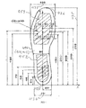
- FIG 4 illustrates a top view of the assembled insole 113, or of the bottom insole 110 or of the top insole 112 of FIG 1, according to one embodiment of the invention.
- the insole 410, 412 has an outer edge 498, the contour line of which substantially forms an insole with size number 47, according to a Swedish shoe size number standard.
- a horizontal system of coordinates is associated with the insole 410, 412.
- the Y-axis of the system of coordinates is parallel with a sagittal plane of a foot during normal operation, i.e. during walking.
- the Y-axis is substantially directed in a frontal direction of the insole 410, 412, i.e. in a straight forward direction during walking with the insole 410, 412, as illustrated in FIG 4.
- the X-axis is orthogonal to the Y-axis and is directed in a medial direction, during normal operation of the insole 410, 412.
- the origin of coordinates is positioned in a backmost edge end 425 of the insole, when being aligned with a foot during normal operation, as illustrated in FIG 4.
- the X-axis and Y-axis define coordinates of length in mm.
- the insole 410, 412 has a length 435 of about 299 mm, i.e. the length from a backmost edge end 425 to a foremost edge end 426 is about 299 mm in the Y-direction, when the insole is so aligned, a heel region width 436 of about 70 mm, i.e.
- the thorough holes 120, 130, 140, 150, 160, 165, 170, 175, 180, 185 of the bottom insole 110 and corresponding matching holes 121, 131, 141, 151, 161, 166, 171, 176, 181, 186 are positioned where they provide relevant tactile feedback.
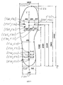
- FIG 5 illustrates a top view of the assembled insole 113, or of the bottom insole 110 or of the top insole 112 of FIG 1, illustrating the positioning of the 10 through holes 520, 521; 530, 531; 540, 541; 550, 551; 570, 571; 565, 566; 560, 561; 575, 576; 580, 581 and 585, 586, respectively, according to a preferred embodiment of the present invention.
- the size and form of the insole of FIG 5 equal the size and form of the insole 410, 412 in FIG 4.
- a system of coordinates is associated with the insole 510, 512 in FIG 5 in the same manner as described for the insole 410, 412, in FIG 4, which is illustrated by an X- and Y-axis in FIG 5.
- the insole 510, 512 has 10 through holes 520, 530, 540, 550, 560, 565, 570, 575, 580, 585, or 521, 531, 541, 551, 561, 566, 571, 576, 581, 586, wherein each respective hole is being positioned as follows:
- the diameter of the 10 through holes 521, 531, 541, 551, 561, 566, 571, 576, 581 and 586 of the top insole 512 is 5 mm
- the diameter of the through holes 520, 530, 540, 550, 560, 565, 570, 575, 580 and 585 is 4 mm, in a most preferred embodiment wherein said through holes matches and functions well with the pin 115, as described further below.
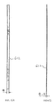
- FIG 6A is a side view of the top insole 612.
- the top insole 612 has preferably a thickness of 6mm at rest, as illustrated in FIG 6A, in order not to become too bulky and provide good compressibility characteristics.
- the top insole 612 is made of an elastic/compressible material allowing it to compress when being subject of pressure, as when it is squeezed between a foot and the bottom insole 610 during normal operation, as during walking.
- the top insole 612 compresses about 1-3 mm, at least in central parts of the regions 452, 453, when the top insole 612 is being installed in a shoe and is being squeezed between a foot and the shoe during walking, wherein the weight load on the foot is in the range of about 10-80 Kg.
- the thickness of the top insole 612 decreases to about 3-5 mm for a specific threshold pressure during walking, corresponding to a maximum weight load of e.g. 30 Kg on the foot.
- the material of the top insole 612 normally allows the insole 612 to resume its substantial rest thickness of about 6 mm during a swing phase of the gait cycle, i.e.
- top insole 612 Normally, the top insole 612 must resume its substantial rest dimensions at least within about 3 seconds after foot pressure release, and more preferably within 1 second after foot pressure release.
- Suitable materials for the top insole 612 are therefore cellular plastic materials, e.g. cellular urethanes which are medium density, microcellular foam materials, or cellular rubber materials, having elastic/compressibility/resilience characteristics meeting above functionality requirements.
- the material of the top insole 612 has a hardness Shore "0" value generally in the range of A 4-30, and preferably in the range of A 5-20, when measured according to the testing specification ASTM D2240, issued by the American Society for Testing and Material, and a vertical resilience rebound value in the range of 4-40 as measured by a Shore instrument Resiliometer, avg (Ball Rebound Tester) according to the testing specification ASTM D 2632-92, issued by the American Society for Testing and Material.
- Urathene materials provided by PORON MEDICAL ® which are commercially available e.g. from Rogers Corporation, High Performance Foams Division, Chicago, USA, are suitable for the top insole 612 according to the invention.
- Table 2 specifies some suitable PORON ® materials for the top insole according to a preferred embodiment.
- these PORON ® materials also provide long term comfort and good hygiene, since they "breathe", are fungal resistant, have a relatively low water absorption and have a relatively smooth surface.
- each PORON ® material in table 2 is associated with a specific weight load limit, which is individual and varies to some extent for different patients.
- the materials indicated on rows 1 and 2 constitute alternatives for substantially the same weight threshold and the materials indicated on rows 4 and 5 constitute alternatives for substantially the same weight threshold.
- a person skilled in the art realises that other PORON ® materials may be used, e.g. for other foot weigh loads.
- the top insole 612 may be made of a polyether material.
- Table 3 specifies various cellular rubber materials, which the top insole 612 is made of, according to an alternative embodiment. These cellular rubbers are commercially available e.g. from National Gummi AB, Fagerdala Cellplaster, Sweden. Shore “0” and Shore “00” are different hardness scales.
- FIG 6B is a side view of the bottom insole 610 according to one embodiment of the invention.
- the bottom insole 610 has a thickness of 0,5 mm and is preferably made of a thermoplastic polyamide material, PA 6, giving it good mechanical and supporting characteristics and a relatively low weight.
- PA 6 is a conventional commercial term for such polyamide material.
- Table 4 specifies the main mechanical characteristics of the PA 6 material, and a person skilled in the art can find other suitable materials with similar characteristics.
- An important aspect is to keep the thickness of the insole arrangement as small as possible, thereby making the insole less bulky which facilitates installation in a shoe, and at the same time provide a distinct and precise tactile feedback.
- the thickness of the bottom insole 610 of 0,5 mm and the top insole 612 of 6 mm at rest constitutes an advantageous combination, according to a preferred embodiment of the invention.
- Table 4 Material Density (kg/m 3 ) Coefficient of elasticity (GPa) Breaking strain (Mpa) Bending Strength % Break Elongation % Water Absorbation% PA 6 1,13 1,4 65 55 200 1,8
- FIG 7 illustrates a top view of an insole 710, 712 according to one embodiment of the invention.
- the contour line 738 represents size nr 35, as illustrated in FIG 7. This allows a cost effective production since the insole 710, 712 need only be produced in one size, i.e. size 47 in this case.
- the position of the 10 through holes 720, 721, 730, 731, 740, 741, 750, 751, 760, 761, 770, 771, 775, 776, 780, 781, 785, 786 are chosen so that the functionality of the insole 710, 712 is not compromised for any shoes size.
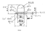
- FIG 8 illustrates a tactile feedback element 815 according to one embodiment of the invention wherein the tactile feedback element is realised as a pin element 815.
- the invention is not restricted to a pin element 815 as shown in FIG 8, but any feedback element providing suitable tactile overload feedback when protruding from the (top) insole may be used, according to the invention.
- the tactile feedback element may be realised as a half circular disk or a half sphere or a spike element made of a suitable firm and rigid material, and designed to be fastened/anchored in the (bottom) insole, but many other possibilities exist, obvious to a person skilled in the art.
- the pin 815 has a tapered head section 8210, a waist section 8220 being circular cylindrical, and a supporting bottom section 8230.
- the upper tapered end of the head 8210 section has a half sphere form, and the upper surface 8231 and the bottom surface 8232 of the bottom section 8230 is planar. This provides good tactile stimulation and supporting characteristics for the insole arrangement according to the invention.
- the maximum diameter 8211 of the head section 8210 is about 4,5 mm
- the total height 816 of the pin is about 6,1 mm
- the diameter 8221 of the waist section 8220 is about 4 mm and the height 8222 of the waist section 8220 is about 0,6 mm
- the maximum diameter 8233 of the bottom section 8230 is about 8 mm
- the height 8234 of the bottom section 8230 is about 0,5 mm.
- the pin 815 may be made of a metallic material, such as automatic screw steel, however other hard materials, such as hard plastic materials, may also be used.
- a suitable automatic screw steel, SS 1914, for the pin 815 comprises 0,06-012% C, about 0,02% Si, 0,9-1,3% Mn, and about 0, 1 % Pb.
- Table 5 specifies some physical data for the automatic screw steel, SS 1914.
- FIG 9A illustrates an assembled insole kit 101 of FIG 1 forming an orthopedic insole 913, when the insole 913 is in a rest condition and not being pressed by a foot 9400.
- the tactile overload feedback element 915 does not protrude from the insole 913 when the insole is at rest, i.e. not being compressed, and thus provides no tactile stimulation to the foot 9400 in this rest condition.
- FIG 9B illustrates an assembled insole kit 101 of FIG 1 forming an orthopedic insole 913, when the insole 913 is in a loaded condition and being pressed by a foot 9400.
- a bottom insole and a top insole of size 45 is then first cut out from a bottom insole 710 and a top insole 712.
- the 5 pins 115, 116, 117, 118 and 119 are then snapped into the bottom insole 710, in through holes 720, 740, 775, 780 and 785 respectively.
- the top insole is then fastened on top of the bottom insole, e.g.
- the so created insole arrangement is installed in a right shoe, which normally is a shoe of the patient.
- the patient then puts this shoe on. Thereafter, the patient in an upright normal walking position puts the right foot/shoe on a balance without putting any weight load on the foot. In this position, the right foot 9400 is not in contact with any of the pins, illustrated by the pin 915 in FIG 9A.
- the person responsible for the rehabilitation activity normally a physiotherapist, then decides a suitable initial maximum weight load threshold, e.g. 20 Kg in this case. Normally, there is no direct correlation between this weight load threshold and the weight of the patient. Thereafter, the patient carefully starts to put weight load on the right foot, thereby compressing the top insole 912.
- the current top insole is replaced with another top insole made of a softer material.
- the initial top insole 912 is made of PORON ® MS-240060-05 and having a Shore "0" hardness value of 12
- this top insole 912 is replaced by a top insole 912 made of e.g. PORON ® 4701-30-15500-04 having a Shore "0" hardness value of 8.
- This procedure is repeated until the patient feels any of the pins 915 within the weight load limit of 20 Kg, meaning that the pin 915 is in contact with the foot 9400, as illustrated in FIG 9B.
- the pin 915 will cause pain if the patient further increases the load, thereby providing an effective auto overload control mechanism.
- the patient then starts the rehabilitation by walking on crutches (or using another suitable support), without risk of overload.
- the top insole 915 is replaced with a new harder top insole, i.e. having a higher Shore "0" value, successively during the healing process, e.g. every 2 weeks.
- the insole according to the invention can be used for both left and right feet, i.e. there is no need to produce "left” and “right” variants.
- the bottom insole and pins may be washed/sterilised and reused, even by a plurality of patients.
- the top insole is normally discarded after being used due to hygienic reasons.
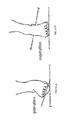
- the insole arrangement according to the invention may be used by a wide range of patient groups, wherein some minor modifications may be necessary, e.g. it may be used in a plaster, it may be used by patients who tend to put a too high lateral or medial load on the foot, i.e. suffering from pronation or supination as illustrated in FIG 10 A and B, or by patients who tend to put a too high frontal load on the foot, referred to as "toe walkers".
- the described insole arrangement according to the invention provides accurate tactile feedback allowing an efficient auto load control of the lower extremities during rehabilitation, and thereby an improved healing and a shortened rehabilitation period.
- the insole arrangement is versatile and cost effective, both to produce and to use. It is user friendly and intuitive in its use. It may be used without notice, which may be of importance to some patient groups. as a person skilled in the art understands.
- the principles of the present invention have been described in the foregoing by means of examples and/or embodiments and/or modes/examples of operation. However, as already stated, many modifications and/or combinations are possible, e.g. regarding the choice of material and the absolute and relative dimensions of different parts of the insole arrangement described above. Furthermore, the insole according to the invention need not necessarily be formed by separate top/bottom insoles as described above, but may instead have a completely integrated design with the bottom/top insole designed as one integrated insole, and with integrated pins etc.
Landscapes
- Health & Medical Sciences (AREA)
- Life Sciences & Earth Sciences (AREA)
- General Health & Medical Sciences (AREA)
- Public Health (AREA)
- Epidemiology (AREA)
- Engineering & Computer Science (AREA)
- Surgery (AREA)
- Animal Behavior & Ethology (AREA)
- Biophysics (AREA)
- Pathology (AREA)
- Veterinary Medicine (AREA)
- Biomedical Technology (AREA)
- Heart & Thoracic Surgery (AREA)
- Medical Informatics (AREA)
- Molecular Biology (AREA)
- Physics & Mathematics (AREA)
- Dentistry (AREA)
- Oral & Maxillofacial Surgery (AREA)
- Chemical & Material Sciences (AREA)
- Materials Engineering (AREA)
- Wood Science & Technology (AREA)
- Footwear And Its Accessory, Manufacturing Method And Apparatuses (AREA)
- Orthopedics, Nursing, And Contraception (AREA)
Priority Applications (4)
| Application Number | Priority Date | Filing Date | Title |
|---|---|---|---|
| EP05112405A EP1797785A1 (de) | 2005-12-19 | 2005-12-19 | Orthopädische Schuheinlage |
| PCT/EP2006/069915 WO2007071676A1 (en) | 2005-12-19 | 2006-12-19 | Orthopedic insole |
| JP2008545019A JP2009519736A (ja) | 2005-12-19 | 2006-12-19 | 整形中底 |
| US12/158,218 US20090044424A1 (en) | 2005-12-19 | 2006-12-19 | Orthopedic insole |
Applications Claiming Priority (1)
| Application Number | Priority Date | Filing Date | Title |
|---|---|---|---|
| EP05112405A EP1797785A1 (de) | 2005-12-19 | 2005-12-19 | Orthopädische Schuheinlage |
Publications (1)
| Publication Number | Publication Date |
|---|---|
| EP1797785A1 true EP1797785A1 (de) | 2007-06-20 |
Family
ID=36405905
Family Applications (1)
| Application Number | Title | Priority Date | Filing Date |
|---|---|---|---|
| EP05112405A Withdrawn EP1797785A1 (de) | 2005-12-19 | 2005-12-19 | Orthopädische Schuheinlage |
Country Status (4)
| Country | Link |
|---|---|
| US (1) | US20090044424A1 (de) |
| EP (1) | EP1797785A1 (de) |
| JP (1) | JP2009519736A (de) |
| WO (1) | WO2007071676A1 (de) |
Cited By (3)
| Publication number | Priority date | Publication date | Assignee | Title |
|---|---|---|---|---|
| WO2011036519A1 (en) * | 2009-09-25 | 2011-03-31 | Bocorocco Italia S.R.L. | Multilayer insole to be fitted in footwear and the like |
| WO2011113171A1 (de) | 2010-03-19 | 2011-09-22 | Rolnic Gmbh | Schuhsohle und schuh |
| CN109152439A (zh) * | 2016-05-26 | 2019-01-04 | 耐克创新有限合伙公司 | 具有感觉反馈系统的鞋类物品的鞋底结构 |
Families Citing this family (11)
| Publication number | Priority date | Publication date | Assignee | Title |
|---|---|---|---|---|
| TWI566747B (zh) * | 2014-06-25 | 2017-01-21 | Hungkuang Univ | Foot center of gravity offset assessment system |
| JP7075032B2 (ja) * | 2016-04-04 | 2022-05-25 | 有限会社スワニー | 緩衝材の製造方法 |
| USD879441S1 (en) | 2016-10-28 | 2020-03-31 | Tammy Terrell Glaze | Sandal sole insert |
| WO2020041719A1 (en) * | 2018-08-24 | 2020-02-27 | Protalus LLC | Insoles with strategic hole placement for enhanced cushioning and performance, and method of making the same |
| USD903268S1 (en) | 2019-02-06 | 2020-12-01 | S. C. Johnson & Son, Inc. | Insole |
| USD906658S1 (en) | 2019-02-19 | 2021-01-05 | S. C. Johnson & Son, Inc. | Insole |
| US11944561B2 (en) * | 2020-11-25 | 2024-04-02 | Braceability, Inc. | Toe walking prevention article |
| CN113208231B (zh) * | 2021-05-18 | 2022-08-23 | 四川大学 | 一种基于足弓数据的3d扁平足矫正鞋垫设计方法 |
| US11992088B2 (en) | 2021-05-31 | 2024-05-28 | Chadrian T. Johnson | Breathable ergonomic shoe insole |
| CN115444649A (zh) * | 2021-06-09 | 2022-12-09 | 清锋(北京)科技有限公司 | 足部矫正件的制造方法和足部矫正件 |
| US12102186B1 (en) | 2023-04-03 | 2024-10-01 | Newton Biomechanics, LLC | Cuboid inserts for improving balance and preventing falls |
Citations (6)
| Publication number | Priority date | Publication date | Assignee | Title |
|---|---|---|---|---|
| US4823799A (en) * | 1986-07-31 | 1989-04-25 | Robbins Stevens E | Biofeedback interface for sensory enhancement of the plantar surface of the foot |
| DE8908109U1 (de) * | 1989-07-03 | 1990-02-01 | Fischer, Helga, 4330 Mülheim | Hygiene-Schuheinlage |
| FR2680452A1 (fr) * | 1991-08-21 | 1993-02-26 | Andre Chaussures Sa | Article chaussant de sport et de loisir. |
| DE19810182C1 (de) * | 1998-03-10 | 2000-03-16 | Univ Eberhard Karls | Vorrichtung zum Erfassen einer Überbelastung des unteren Bewegungsapparates und/oder der Wirbelsäule einer Person |
| US6237256B1 (en) * | 1998-08-12 | 2001-05-29 | Sunnybrook And Women's College Health Sciences Centre | Balance-enhanced insert for footwear |
| US20040230139A1 (en) * | 2003-05-15 | 2004-11-18 | Freddie Chang | Floating massage pad structure |
Family Cites Families (12)
| Publication number | Priority date | Publication date | Assignee | Title |
|---|---|---|---|---|
| US4047310A (en) * | 1976-04-19 | 1977-09-13 | Sunoo Hyeng P | Fatigue relieving foot appliance |
| US4387516A (en) * | 1980-12-22 | 1983-06-14 | L & A, Inc. | Universal insole |
| US4694831A (en) * | 1984-01-04 | 1987-09-22 | Seltzer Charles J | Massage footwear |
| US4819644A (en) * | 1987-10-29 | 1989-04-11 | Cherniak Jaime G | Base plate to form an insole for an orthotic foot brace and a method of forming an orthotic foot brace |
| US5216825A (en) * | 1992-01-21 | 1993-06-08 | Brum Kenneth A | Odor adsorbing contoured support inner sole |
| US5352189A (en) * | 1992-02-19 | 1994-10-04 | Tecnol Medical Products, Inc. | Ankle brace walker |
| DE4406063A1 (de) * | 1994-02-24 | 1995-08-31 | Prodomo Sa | Einlegesohle |
| US5551173A (en) * | 1995-03-16 | 1996-09-03 | Chambers; Mark D. | Comfort insole |
| JP2003052407A (ja) * | 2001-08-10 | 2003-02-25 | Kazuya Sasaki | 靴の中敷用指圧器 |
| US20040111924A1 (en) * | 2002-04-23 | 2004-06-17 | Raffaele Riccardi | Self-stimulating clogs for performing a zonal therapy with changeable stimulation points |
| US6742289B2 (en) * | 2002-07-01 | 2004-06-01 | Medical Device Group, Inc. | Stress reduction kit and method of using same |
| US7644522B2 (en) * | 2005-10-12 | 2010-01-12 | Manuel Ramirez Martinez Ramirez | Soles with adjustable and interchangeable supports |
-
2005
- 2005-12-19 EP EP05112405A patent/EP1797785A1/de not_active Withdrawn
-
2006
- 2006-12-19 JP JP2008545019A patent/JP2009519736A/ja active Pending
- 2006-12-19 WO PCT/EP2006/069915 patent/WO2007071676A1/en active Application Filing
- 2006-12-19 US US12/158,218 patent/US20090044424A1/en not_active Abandoned
Patent Citations (6)
| Publication number | Priority date | Publication date | Assignee | Title |
|---|---|---|---|---|
| US4823799A (en) * | 1986-07-31 | 1989-04-25 | Robbins Stevens E | Biofeedback interface for sensory enhancement of the plantar surface of the foot |
| DE8908109U1 (de) * | 1989-07-03 | 1990-02-01 | Fischer, Helga, 4330 Mülheim | Hygiene-Schuheinlage |
| FR2680452A1 (fr) * | 1991-08-21 | 1993-02-26 | Andre Chaussures Sa | Article chaussant de sport et de loisir. |
| DE19810182C1 (de) * | 1998-03-10 | 2000-03-16 | Univ Eberhard Karls | Vorrichtung zum Erfassen einer Überbelastung des unteren Bewegungsapparates und/oder der Wirbelsäule einer Person |
| US6237256B1 (en) * | 1998-08-12 | 2001-05-29 | Sunnybrook And Women's College Health Sciences Centre | Balance-enhanced insert for footwear |
| US20040230139A1 (en) * | 2003-05-15 | 2004-11-18 | Freddie Chang | Floating massage pad structure |
Cited By (6)
| Publication number | Priority date | Publication date | Assignee | Title |
|---|---|---|---|---|
| WO2011036519A1 (en) * | 2009-09-25 | 2011-03-31 | Bocorocco Italia S.R.L. | Multilayer insole to be fitted in footwear and the like |
| CN102209477B (zh) * | 2009-09-25 | 2015-08-19 | 博克罗科意大利有限责任公司 | 一种用于配合在鞋中的多层鞋垫及其鞋类 |
| AU2010299605B2 (en) * | 2009-09-25 | 2016-08-25 | Bocorocco Italia S.R.L. | Multilayer insole to be fitted in footwear and the like |
| WO2011113171A1 (de) | 2010-03-19 | 2011-09-22 | Rolnic Gmbh | Schuhsohle und schuh |
| CH702899A1 (de) * | 2010-03-19 | 2011-09-30 | Rolnic Gmbh | Schuhsohle und schuh. |
| CN109152439A (zh) * | 2016-05-26 | 2019-01-04 | 耐克创新有限合伙公司 | 具有感觉反馈系统的鞋类物品的鞋底结构 |
Also Published As
| Publication number | Publication date |
|---|---|
| US20090044424A1 (en) | 2009-02-19 |
| JP2009519736A (ja) | 2009-05-21 |
| WO2007071676A1 (en) | 2007-06-28 |
Similar Documents
| Publication | Publication Date | Title |
|---|---|---|
| EP1797785A1 (de) | Orthopädische Schuheinlage | |
| CA2643673C (en) | An orthopedic foot appliance | |
| US4633877A (en) | Dynamic foot support and kit therefor | |
| US5662123A (en) | Capacitive biofeedback sensor with resilient polyurethane dielectric for rehabilitation | |
| US6349487B1 (en) | Foot leverage system and method | |
| US9005140B2 (en) | Weight monitoring apparatus, weight monitoring system, and related methods thereof | |
| Postema et al. | Primary metatarsalgia: the influence of a custom moulded insole and a rockerbar on plantar pressure | |
| EP2859807A1 (de) | Orthopädisches Fußhilfsmittel | |
| US7493810B2 (en) | Device for mechanical weight bearing indication with load range capability | |
| US20040003514A1 (en) | Foot orthosis | |
| JP2008520323A (ja) | 縦方向固有感覚受容性、外受容性、圧受容性および/もしくは反射性刺激用足底部材 | |
| Choi et al. | Effects of custom-made insoles on idiopathic pes cavus foot during walking | |
| Bagherzadeh Cham et al. | The effects of Vibro-medical insole on vibrotactile sensation in diabetic patients with mild-to-moderate peripheral neuropathy | |
| CN214072052U (zh) | 鞋中底及鞋类制品 | |
| Janisse | Indications and prescriptions for orthoses in sports | |
| Sadeghi et al. | Effects of Foot Sole on Ground Reaction Forces During Walking in Male Athletes With Flexible Flat Foot | |
| EP1038459A1 (de) | Hebelkraftanordnung für Füsse und Bewegungsverbesserung bei deren Verwendung | |
| KR20180090548A (ko) | 발가락 교정구 | |
| JPH02261447A (ja) | 足裏支持体 | |
| KR101697135B1 (ko) | 스마트 지골 교정 장치 | |
| CN107568832B (zh) | 防塌陷的扁平足矫形鞋垫结构 | |
| CN216393231U (zh) | 含梯度分布的分层足部矫形结构 | |
| Permsombat et al. | Effects of customized foot orthoses on lower limbs kinematics in adults with highly pronated foot | |
| CN215021760U (zh) | 步态训练足垫及装置 | |
| Gorokhova et al. | The Usage of Smart Materials for Development of Rehabilitation Orthopedic Device for Plantar Fasciitis Treatment |
Legal Events
| Date | Code | Title | Description |
|---|---|---|---|
| PUAI | Public reference made under article 153(3) epc to a published international application that has entered the european phase |
Free format text: ORIGINAL CODE: 0009012 |
|
| AK | Designated contracting states |
Kind code of ref document: A1 Designated state(s): AT BE BG CH CY CZ DE DK EE ES FI FR GB GR HU IE IS IT LI LT LU LV MC NL PL PT RO SE SI SK TR |
|
| AX | Request for extension of the european patent |
Extension state: AL BA HR MK YU |
|
| 17P | Request for examination filed |
Effective date: 20071120 |
|
| 17Q | First examination report despatched |
Effective date: 20071221 |
|
| AKX | Designation fees paid |
Designated state(s): AT BE BG CH CY CZ DE DK EE ES FI FR GB GR HU IE IS IT LI LT LU LV MC NL PL PT RO SE SI SK TR |
|
| STAA | Information on the status of an ep patent application or granted ep patent |
Free format text: STATUS: THE APPLICATION IS DEEMED TO BE WITHDRAWN |
|
| 18D | Application deemed to be withdrawn |
Effective date: 20090423 |