EP1797389B1 - Gasbetriebene schusswaffe mit indirekter beaufschlagung des verschlusses. - Google Patents
Gasbetriebene schusswaffe mit indirekter beaufschlagung des verschlusses. Download PDFInfo
- Publication number
- EP1797389B1 EP1797389B1 EP05858155.4A EP05858155A EP1797389B1 EP 1797389 B1 EP1797389 B1 EP 1797389B1 EP 05858155 A EP05858155 A EP 05858155A EP 1797389 B1 EP1797389 B1 EP 1797389B1
- Authority
- EP
- European Patent Office
- Prior art keywords
- automatic
- assembly
- firearm
- cylinder
- gas
- Prior art date
- Legal status (The legal status is an assumption and is not a legal conclusion. Google has not performed a legal analysis and makes no representation as to the accuracy of the status listed.)
- Revoked
Links
Images


Classifications
-
- F—MECHANICAL ENGINEERING; LIGHTING; HEATING; WEAPONS; BLASTING
- F41—WEAPONS
- F41A—FUNCTIONAL FEATURES OR DETAILS COMMON TO BOTH SMALLARMS AND ORDNANCE, e.g. CANNONS; MOUNTINGS FOR SMALLARMS OR ORDNANCE
- F41A5/00—Mechanisms or systems operated by propellant charge energy for automatically opening the lock
- F41A5/18—Mechanisms or systems operated by propellant charge energy for automatically opening the lock gas-operated
- F41A5/26—Arrangements or systems for bleeding the gas from the barrel
- F41A5/28—Adjustable systems
Definitions
- the disclosed embodiments relate to firearms and, more particularly, to a firearm having an indirect gas operating system.
- Document US 4 244 273 A discloses a semi automatic rifle having a front sight assembly comprising therein a cylinder having therein a lower longitudinally extending port or slot and upper exhaust ports.
- a port extends vertically within the front sight assembly connects with a port in the barrel of the rifle.
- the front sight assembly is so aligned and positioned on the barrel so that port 59 and 62 are in exact alignment.
- a piston integrally connected to a rearwardly extending piston rod is received in the cylinder.
- Document US 3 618 457 A discloses a firearm according to the preamble of independent claim 1, having a barrel and a bracket mounted on the barrel near the outer end thereof.
- a tube is mounted in a bore in the bracket and retained therein by a pin.
- a radial gas port in the barrel and a passage in the bracket provide communication between the bore through the barrel and a gas passage within the tube.
- a piston is slidably mounted in the tube, and the tube has a plurality of radial exhaust ports therein.
- Document CH 631 542 A5 discloses a device for adjusting the firing rate of an automatic firearm.
- the device comprises a cylindrical insertion piece inserted in front of a cylinder in a gas block housing.
- the insertion piece comprises an inner part with has disc-shaped intermediate walls 21 to achieve a constriction of the gas flow taken from the barrel and an outer part with a passage in which a slide provides different venting openings to adjust the firing rate.
- an automatic firearm having an indirect gas operating system
- a bolt assembly having a striking surface, the bolt assembly enclosed within and operates within a receiver assembly; a barrel assembly having a bore, the barrel assembly coupled to a receiver assembly; an indirect gas operating system with piston, rod assembly and striking rod and a cylinder receiving said piston; and a gas block fitted to the barrel assembly; wherein, gas discharged from a fired cartridge displaces the piston and causes the striking rod to strike the striking surface displacing the bolt assembly, and wherein the striking rod and the striking surface disengage each other after the striking rod strikes the striking surface, characterized in that said gas block is made of a single part in which said cylinder is located, said cylinder being in direct fluid communication with the bore through a passage in said gas block, said cylinder having an exhaust port within said gas block, said gas block being equipped with means for regulating a flow of gas between said bore and said cylinder, in said passage, or between said
- FIG. 1 there is shown, a side elevation view of an automatic firearm 30 capable of automatic or semiautomatic fire incorporating features in accordance with an exemplary embodiment.
- an automatic firearm 30 capable of automatic or semiautomatic fire incorporating features in accordance with an exemplary embodiment.
- the present invention will be described with reference to the embodiments shown in the drawings, it should be understood that the present invention can be embodied in many alternate forms of embodiments within the scope of appended independent claim 1. .
- any suitable size, shape or type of elements or materials could be used.
- Firearm 30 is illustrated as generally having an M4 or M16 type automatic firearm configuration. However, the features of the disclosed embodiments, as will be described below, are equally applicable to any desired type of automatic firearm. Firearm 30 may have operational features such as disclosed in United States Patents 5,726,377 , 5,760,328 , 4,658,702 and 4,433,610 , and patent applications Serial No. 60/564,895 ; 10/836,443 filed respectively on 4/23/04 and 4/30/ 04. The firearm 30 and its sections described in greater detail below is merely exemplary, and in alternate embodiments the firearm 30 may have other sections, portions or systems. Firearm 30 may incorporate a hand guard 40, a receiver section 42, a barrel 24, and stock 44. As will be described further below, hand guard 40 may further incorporate vent holes, ribbing, heat shields or double heat shields and liners to facilitate cooling of the barrel 24 while keeping hand guard 40 at a temperature sufficient for an operator to hold the handguard.
- Firearm 30 has an indirect gas operating system 60 facilitating automatic or semi-automatic operation as will be described below.
- the indirect gas operating system 60 is adjustable, allowing the operator to vary cyclic rate as desired.
- the system 60 has a gas block 8 having a cylinder therein. Gas block 8 is fitted to a barrel assembly 24 where barrel 24 has a bore with the cylinder being in fluid communication with the bore through a port.
- a piston and rod assembly 62 having a piston and a striking rod is housed within hand guard 40 and receiver 42. The piston is fitted to the cylinder.
- a bolt carriage assembly 64 is provided within receiver 42. The bolt carriage assembly 64 has a striking surface cooperating with the rod of the operating system 60.
- Hand guard 40 When a cartridge is fired, pressurized gas enters the cylinder, displaces the piston and causes the striking rod to strike the striking surface displacing the bolt assembly.
- the cyclic rate selector interfaces with the pressurizing gas in the cylinder to vary the bolt carriage cycle rate during automatic operation of the firearm.
- Hand guard 40 may have features such as disclosed in United States Patents 4,663,875 and 4,536,982 .
- Hand guard 40 and receiver section 42 may be configured to support such rails as a "Piccatiny Rail" configuration as described in Military Standard 1913, which is hereby incorporated by reference herein in its entirety.
- the rails may be made from any suitable material such as hard coat anodized aluminum as an example.
- Front sight assembly 48 is shown mounted to rail 50 of hand guard 40.
- Front sight assembly 48 is removable, allowing alternate mounting of desired accessory in its place such as a telescopic sight or laser sight.
- front sight 48 may be mounted to barrel 24 as shown in the exemplary embodiment in Fig. 8 .
- Rear sight assembly 52 is provided and mounted to receiver section 42.
- Rear sight assembly 52 incorporates sight ring 54 and sight adjustment knobs 56 and 58. Sight adjustment knobs 56 and 58 are provided to adjust the position of sight ring 54 relative to the barrel 24 and front sight 48 for accurate target sighting.
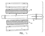
- FIG. 2 - 3 there is shown respectively a partial top isometric view and a schematic bottom isometric view of the front sight section 48 of the firearm shown in Fig. 1 .
- FIGs. 4 - 10 there is shown an exploded view of the front sight section 48 and detailed views of the parts included in the assembly of the front sight section of the firearm shown in Fig. 1 .
- Front sight 48 is shown as a detachable or removable front sight within this embodiment mounting to a "Piccatiny" rail though in alternate embodiments the mounting may have any desired configuration. As seen in Fig.
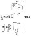
- the front sight assembly generally comprises base sections 162, front sight post 150, spring loaded pivot assembly 154 and mounting retention members 161A, 161B (see also Fig. 3 ).
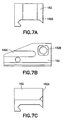
- Base 162 includes complementing mounting for the Piccatiny rail to which the front sight assembly 48 in this embodiments is removably mounted.
- the mounting retention members include clamping bracket or section 161A that is fastened with a locating pin (not shown) to side 162A of the base 162 to clamp the Piccatiny rail. Tightening nut 161B generates clamping pressure to hold the base 162 and bracket 161A on the rail.
- Base 162 (seen best in Fig. 7 ) and front sight post 150 (see best in Fig.
- the front sight post 150 is mounted to the base with pin 154 (see Fig. 4 ).
- the front sight has a rounded feature 150E that is shaped to coincide with the edges of the hole or ring 152 upon alignment of front and rear sights making it much easier for a user to acquire targets and center the weapon with the combination.
- the front sight 150 is shown as a raised sight with a folding construction allowing a user to keep the sight in the position shown or rotate the sight to a lowered position. Spring loaded detents lock the sight post 150 in the up or lowered positions.
- the pivot pin 154 see also Figs.
- a squared head 156 having tapered features 158 that complement angled edges 162E of receiving hole 162B in base 162 (see Fig. 8 ).
- the taper facilitates self centering, improved locking and position locking and reduced sight vibration by taper engagement with a mating feature 160 in base 162 aided by a spring load or bias from spring 164.
- the sight post may have any other suitable spring loaded detents holding the sight post in desired positions.
- the pivot pin, positioned within mounting bore 150H, is locked to the sight post 150 by a locking pin (not shown) that mates with slot 166 and hole 168.
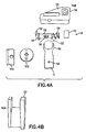
- a thread-on cap feature 170 (see also Fig. 9A ) is threaded onto the pin end and retains the spring 164 (see Fig. 5 ).
- FIG. 10 there is shown a side elevation view of the firearm shown in Fig. 1 with the hand guard removed.
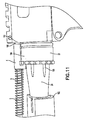
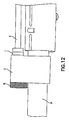
- Fig's. 11 and 12 there is shown a partial side elevation view of the firearm shown in Fig. 1 with the hand guard removed.
- Fig. 13 there is shown an exploded view of an automatic firearm incorporating features in accordance with an exemplary embodiment.
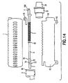
- Fig. 14 there is shown a side exploded view of the barrel, receiver, hand guard and gas piston assembly of the firearm shown in Fig. 1 .
- firearm 30 has an indirect gas operating piston system 60 (see Fig. 10 ).
- the indirect gas operating system 60 has a gas block 8 having a cylinder 68 therein.
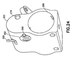
- the gas block is schematically shown in perspective in Fig. 16 .
- Gas block 8 is shaped to be mounted to the barrel assembly 24.
- Barrel 24 has a bore (not shown) for exhausting firing gases.
- the cylinder 68 in the gas block is in fluid communication with the bore through a port 68P disposed on a surface of the gas block facing the barrel.
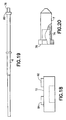
- the piston 7 (see Fig. 20 ) is movably fitted to the cylinder 68.
- the striking rod 6 (see also Fig. 19 ) is fixedly joined at its front end, for example by a threaded connection, to the piston 7.
- piston 7 has a bore 74 that accepts the tip 76 of rod 6.
- Piston 7 has a shoulder 78 that mates with flange 80 of rod 6.
- other engagement techniques could be provided.
- Gas block 8 is fitted onto barrel 24.
- gas block 8 has a cylinder 68 that houses piston 7 with the piston 7 engaging rod 6 that extends back to engage bolt assembly 64.
- the bolt carriage assembly 64 is provided within receiver 42 (see Fig. 13 ) with the bolt assembly carriage 64 having a striking or engagement surface that is engaged by the rear end of the operating rod as will be described below.
- Guide 4 houses operating rod 6 allowing operating rod 6 to slide freely relative to the receiver.
- Guide 4 also has a feature 108 that mates with mating feature 110 (see Figs. 14 , 15 ) of receiver 42 to correctly position rod 6 relative to the bolt carriage assembly within receiver 42.
- Spring 5 is provided between shoulder 72 of rod 6 and guide 4 to bias the rod toward the gas block.
- the indirect gas operating system 60 in this embodiment has valving or pressure regulator to allow the user to select desired operating pressure and hence to select the cyclic rate.
- the regulator is incorporated into the gas block, and adjustment is provided by a rotating knob 10 (a perspective view of which is shown in Fig. 17 ).
- the gas pressure that is exerted on the piston may be varied by the user by loosening fastener 11 (see Fig. 13 ) and rotating knob 10.
- the knob 10 By rotating knob 10 to selectable positions, different charges or rates are applied to the piston by variable gas pressure and selectable force.
- the knob 10, in the embodiment shown in Figs. 17-18 generally covers the end 82 of gas block 8 opposing the piston (see also Fig. 15 ).
- knob 10 covers or interfaces with a portion of the cylinder 68 that has an exhaust port 84.
- the knob could have a different shape or be in a different position.
- the cylinder 68 (see Fig. 16 ) has one or more exhaust orifices or ports 84 formed in the front end 82 of the gas block.
- the port 84 (one is shown, but any suitable number may be provided) is offset from the center of the cylinder 68 or the knob.
- the port 84 is located in a region generally between the cylinder 68 and barrel 24, and away from the top most portion of the gas block. This allows the gas block profile (i.e.
- port 84 has an inlet 84I in the end face 68E of the cylinder 68 opposing the piston I.
- the port inlet may be located on any other desired surface of the cylinder.
- Blind hole 86 may also be provided to locate features 88, 90 of knob 10 correctly.
- the end of the gas block may also have a threaded hole for fastener 11, though in alternate embodiments the gas block may have an integral fastening post onto which the knob 10 is threaded.
- the knob also has one or more bosses complementing port 84 and having exhaust orifices or ports 92, 94 with different bore sizes or diameters in the embodiment shown offset from the center of the cylinder or the knob.
- the holes 92, 94 are sized for each to allow a different desired exhaust flow such as may be used with different particular charges.
- One boss position may be blind or has no hole or is completely blocked.
- the knob may have any desired number of selectable positions. This allows the user to have increased flexibility as to the ammunition or charge used.
- the effective size of the port or orifice exiting the cylinder to ambient air may be increased, decreased or eliminated allowing gas to either blow through the orifice at a variable rate, thus controlling the amount and pressure of gas applied to the piston.
- exhaust gasses are directed toward the muzzle of the firearm, away from the operator; in alternate embodiments, other directions or locations could be provided.
- the gas block 8 and the piston 7 and rod assembly 6 fits within the hand guard assembly in a low profile relative to other block systems.
- the embodiment shown may employ a short barrel 24 with a shorter operating rod that results in higher impact loads to the bolt assembly.
- firearm 30 is illustrated in the figures as having a general M4 type configuration for example purposes, but may be any suitable type of automatic or semi-automatic firearm having an indirect gas operating system 60'.
- firearm 30 may have a bolt carriage assembly 64 having a striking surface 126 (see Fig. 32 ), where the bolt assembly is enclosed within the receiver assembly 42 (see also Fig. 13 ) where barrel assembly 24 may be coupled to the receiver assembly 42.
- gas piston assembly 60' in accordance with the exemplary embodiment described herein, may be used with any type of automatic or semi-automatic firearm having an indirect gas operating system operating the bolt assembly. Except as otherwise noted, indirect gas operating system 60' is similar to gas operating system 60 described before. Similar features are similarly numbered.
- Gas block 202 having cylinder 206 may be fitted to barrel assembly 24, with the cylinder 206 in communication with the bore 208.
- Piston and rod assembly 62' having a piston 7' and a engaging rod 6' have piston 7' fitted to cylinder 206. Gas discharged from a fired cartridge displaces piston 7' and causes engaging rod 6 to strike striking surface 126 displacing bolt assembly 64.
- Exhaust port 218 may be in communication with cylinder 206 and piston 7 whereby gas is exhausted when piston 7' reaches for example an end stroke position opening exhaust outlet 224 in the cylinder 206.
- other exhaust ports may be provided or selectable between positions.
- the cylinder 206, and piston 7' therein are in communication with barrel bore 203 via passages 240, 242 and an intermediate throttle or regulator 214 having selectable positions 230, 232 (see Fig. 21 , 22 ) corresponding to selectable firing rates.
- the regulator 214 is shown as having two selectable positions 230, 232 corresponding to two selectable firing rates. In alternate embodiments, more or less selectable positions, corresponding to more or fewer selectable firing rates may be provided.
- Intermediate regulator 214 may be switched between the two selectable positions 230, 232 by an operator without the use of specific tools (e.g. screwdriver, wrench, dedicated key) where the operator simply rotates an arm of the selector 214 as shown in positions 230, 232.
- piston 7' may be spring biased toward cylinder 206 and piston 7' and striking rod 6' may be separable (e.g. The striking rod 6' is fixedly joined at its front end, for example by a threaded connection, to the piston 7'.
- piston 7' has a bore 74' that accepts the tip 76' of rod 6'.
- Piston 7' has a shoulder 78' that mates with flange 80' of rod 6'.
- piston 7' and rod 6' may be monolithic.
- the piston assembly may have a piston end 220, and a striking end 236 (see Fig. 13 ), where the piston end may be fitted to cylinder 206.
- gas discharged from a fired cartridge displaces piston 7' and causes striking end to strike and displace bolt assembly 64.
- the intermediate regulator 214 throttles or regulates the flow of the pressurized gas from the barrel bore 208 to the cylinder 206.
- intermediate regulator 214 may have two selectable positions 230, 232 corresponding to two selectable firing rates, such as, for example 800 and 1000 rounds per minute.
- the intermediate regulator 214 may have throttling orifices 228, 226 positioned in communication passages 240, 242 as shown for example in Fig. 28 .
- any desired number of throttling orifices may be used and may have any desired shape.
- the cylinder 206 in communication with the bore 208 via the first orifice 228 when intermediate regulator 214 is in a first selectable position 230.
- the cylinder 206 is in communication with bore 208 via second orifice 226, when intermediate regulator 214 is in a second selectable position 232.
- first and second selectable positions 230, 232 correspond to first and second firing rates where the first and second orifices 226, 228 are of different size. Such size may be determined by orifice effective flow diameter, or other suitable feature.
- intermediate regulator 214 is rotationally housed within block 202.
- intermediate regulator 214 has orifices 226, 228 positioned to connect passages 240, in communication with bore 208 in barrel 24 and passage 242 in communication with the cylinder 206.
- regulator passages 216 connects passages 240, 242 throttling flow from barrel 24 to cylinder 206 corresponding to one selectable cyclic rate.
- regulator 214 when the regulator 214 is rotated so that regulator passage 228 connects passages 240, 242, flow between barrel and cylinder is throttled corresponding to another selectable cyclic rate.
- he embodiment shown may be provided with any suitable combination of features, such as where bolt assembly 64 may have a removable striking surface 126 (see Figs. 33, 34 ).
- cylinder 206 may be fitted to the barrel assembly 24 with cylinder 206 in communication with bore 208 via intermediate regulator 214 having two selectable positions 230, 232 corresponding to two selectable firing rates.
- gas discharged from a fired cartridge displaces piston 7' and causes the striking end of the engaging rod 6 to displace bolt assembly 64 where intermediate regulator 214 regulates the flow of the gas from the bore 208 to the piston 7'.
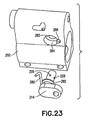
- indirect gas operating system 60' has a gas block 202 having a cylinder 206 therein.
- gas block is shown in perspective.
- Gas block 202 is shaped to be mounted to the barrel assembly 24.
- Gas block 202 has a retaining clip or pin 280 provided to retain selector 214. Retaining clip 280 may be removed from block 202 to remove selector 214.
- Gas block 202 has recess 282 provided to accept selector 214.
- Recess 282 has portion 284 sized to house retaining and locating features 292 of selector 214.
- Gas block 202 further has detent pin 286 provided to locate and hold selector 214 in a selectable position.
- Gas block 202 further has bore 288 provided therein for locating and fastening to barrel 24 with suitable fasteners and fastening features.
- intermediate regulator or selector 214 is shown.
- selector 214 is rotatably mounted in block 202 where retaining feature 292 comprising, for example, a recess that cooperates with clip 280 whereby selector 214 is retained in housing 202 when clip 280 is in place.
- Selector 214 has orifices 226, 228 that may be of different size. In the embodiment shown, orifices 226, 228 are intersecting; in alternate embodiments, orifices 226, 228 may not be intersecting. In alternate embodiments, more or fewer orifices may be provided.
- Selector 214 has shaft 290 which engages in corresponding bore 282 of block 202 whereby gas is directed through ports in the selected orifice.
- Detent features 294, 296 are provided in selector 214 and cooperate with a spring loaded member, such as flexure 286, of block 202 to hold the selector in the desired position.
- barrel 24 has a bore 208, an exhaust port 212 disposed to communicate with the passage 240 in the gas block facing the barrel.
- Gas block 202 is fitted onto barrel 24 by appropriate fastening methods.
- gas block 202 has a cylinder 206 that houses piston 7' with the piston 7' engaging rod 6' that extends back to engage bolt assembly 64.
- the bolt carriage assembly 64 is provided within receiver 42 with the bolt assembly 64 having a striking or engagement surface that is engaged by the rear end of the operating rod.
- pressurized gas enters cylinder 206, displaces piston 7' and causes the striking rod 6' to strike the striking surface displacing the bolt assembly.
- a spring similar to spring 5 in Fig. 13 , is provided between shoulder 72' of rod 6' and guide 4 to bias rod 6' toward cylinder 202.
- selector 214 which as noted before is rotatably mounted within block 202, is rotated to select the desired rate.
- the amount of gas flow and / or pressure that is exerted on the piston may be varied by the user when rotating selector 214.
- selector 214 By rotating selector 214 to selectable positions, different charges or rates are applied to the piston by variable gas pressure, flow and selectable force.
- Exhaust port 218 may vent gas upon sufficient motion of piston 7', such as where front 220 of piston 7' passes port 224 of block 202 in communication with vent 218.
- the selector could have a different shape or be in a different position.
- Throttling orifices 226, 228 in the selector may be sized for each to allow a different desired flow such as may be used with different particular charges or with different desired firing rates. This allows the user to have increased flexibility as to the firing rate, ammunition or charge used.
- the effective size of the port or orifice between bore 208 and cylinder 206 increased, decreased or eliminated allowing gas to blow through the orifice at a selectable variable rate, and throttling the amount and pressure or flow of gas applied to the piston.
- more or less holes or orifices may be provided.
- exhaust gasses 218 are directed toward the muzzle of the firearm, away from the operator; in alternate embodiments, other directions or locations could be provided.
- the gas block 202 and the piston 7' and rod assembly 6' fits within the hand guard assembly in a low profile relative to other block systems.
- the embodiment shown may employ a short barrel 24 with a shorter operating rod that results in higher impact loads to the bolt assembly.
- FIG. 29 there is shown a front cross section of a gas block section of an indirect gas operating system 60" in accordance with yet another embodiment.
- the gas block 252 in this embodiment has intermediate regulator 258 that slides rectilinearly within the gas block.
- intermediate regulator 258 may be slidably selectable between two selectable positions 260, 262 corresponding to two different firing rates.
- bore 208 is in communication with cylinder 254 and piston end 220 via passages 264, 266, throttling orifice 270 and passage 272.
- bore 208 is in communication with cylinder 254 and piston end 220 via passages 264, 266 throttling orifice 268 and passage 272.
- Spring loaded detents 256 may be provided to allow intermediate regulator 258 to be retained in position 260 or 262 where a user may simply snap the regulator into either position by pushing on the opposing end. In this manner, the firing rate may be changed without the use of tools in the field.
- Exhaust vent 276 may be provided to vent gas' when the piston extends to a predetermined location. In alternate embodiments, more or less positions or orifices may be provided, for example a third or fourth position where a different orifice size or no orifice is present.
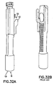
- FIG. 32A there is shown a view of a bolt carriage assembly 64 of the firearm shown in Fig. 1 in accordance with an exemplary embodiment.
- FIGs. 33 - 34 there is shown an exploded view of a bolt assembly of the firearm shown in Fig. 1 .
- the embodiment shown may employ a short barrel 24 with a shorter operating rod 6 that results in higher impact loads to the bolt carriage assembly.
- the bolt carriage assembly 64 is subjected to such higher impact and operating loads.
- the assembly is a conventional (M4) direct gas operated bolt carriage assembly.
- Bolt carriage assembly 64 has a bolt carriage frame or carrier 120, a strike portion or key assembly 122 and a stop member 124.
- Strike portion 122 is struck by rod 6 (or rod 6') at face or portion 126. As seen in Fig. 13 strike face 126 is located to be substantially coaxial with the operating rod 6.
- the strike portion 126 is suitably shaped (e.g. tapered) to direct loads imparted by rod 6 into the base 122B that engages the strike portion 122 to the carrier frame.
- Strike portion 122 has a keyed portion 128 on base 122B that engages corresponding keyed lateral grooves 120G in frame 120 that form a generally T-shaped keyway. Additionally a front notch engagement portion 130 may be provided in the base 122B of strike portion 122 to engage a corresponding front key groove 120GF in carrier 120.
- the keys 128 on the base of the strike portion 122 are sized to form a press or force fit with the keyways 120B, 120GF of the carrier frame.
- stop piece 124 is fastened to carrier 120 using fastener 134 to further retain strike portion 122.
- Stop piece 124 has a lock step engaging the end of the strike 122.
- the key ways could be provided within the strike portion and a corresponding interface on the carrier. In this manner, the bolt assembly 64 may withstand higher impact and operating loads.
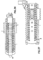
- FIG. 35 there is shown a side elevation view of a hand guard assembly 40 of the firearm shown in Fig. 1 .
- Fig. 36 there is shown a top elevation view of a hand guard assembly 40 of the firearm shown in Fig. 1 .
- Fig. 37 there is shown a side elevation view of a hand guard assembly 40 of the firearm shown in Fig. 1 .
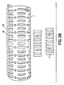
- Fig. 38 there is shown a side elevation view of a hand guard 1 and removed relocatable rails of the firearm shown in Fig. 1 .
- FIG. 39 there is shown an isometric view of a front end of hand guard 1 of the firearm shown in Fig. 1 .
- Hand guard 40 has an aluminum shell 1 that in this embodiment is of unitary construction and has vent holes and external ribbing. Hand guard 40 is ergonomically sized to allow a user to comfortably grip the guard. Shell 1 is mounted to the receiver 42 and is floating relative to barrel 24 and barrel radiator 102. In alternate embodiments, multiple shells, inner ribbing, heat shields or double heat shields and liners to facilitate cooling of the barrel 14 while keeping hand guard 40 at a temperature sufficiently low for an operator could be provided.
- Removable and relocatable rails 2, 136 may be provided on hand guard 40 and may be permanently mounted or removably mounted and be removable or moveable to different locations on hand guard 40. The rails and mounting system to the hand guard may be substantially similar to rails described in U.S.
- the guard mount to the receiver has an upper lug 138 that is provided to interface and mount to a corresponding slot 140 in the frame of the upper rail of upper receiver 42 (see Fig. 31 ).
- Removable bottom lug 26 is provided to engage a corresponding slot or clevis 142 (see Fig. 30 ) machined into the standard front bottom lug attachment of the lower and upper receiver 42.
- the rear of guard 1 has a lug 26 recessed into the bottom clevis 142.
- guard 1, via lug 26 is locked to lower receiver 144 and upper receiver 42 with the same pin 146 (see Fig. 13 ) and guard 1 is further locked to upper receiver via lug 138 and pin 27 (see Fig. 13 ).
- FIG. 30A there is shown a bottom view of a receiver assembly 42 of the firearm shown in Fig. 1 .
- FIG. 31A there is shown a top view of a receiver 42 of the firearm shown in Fig. 1 .
- FIG. 30B 31B are respective bottom and top views of a conventional M4 receiver as shown for example purposes.
- slot 140 in the frame of the upper rail of upper receiver 42 is provided to interface and mount corresponding lug 138 of hand guard 1.
- slot or clevis 142 is machined into the front bottom lug, that forms the attachment of the lower and upper receivers, to engage the corresponding removable lower lug 26 of hand guard 40.
- guard 1 has a lug 26 recessed into the bottom clevis 142.
- guard 1 when mounted, guard 1 is locked via lug 26 to lower receiver 144 and upper receiver 42 with the pin 146 connecting the lower and upper receivers to each other and guard 1 is further locked to upper receiver via lug 138 and pin 27 (see Fig. 8 ).
- the hand guard 1 covers the indirect gas operating system 60.
- the gas block 8 (or gas block 202, 252) is housed inside the guard 1. This is facilitated by the low profile of the gas block. As seen in Fig.
- the guard may include an inner groove 1G or channel in which the gas operating system 60 is disposed.
- the channel provides sufficient clearance around the gas operating system 60 for unencumbered operation.
- Claim 1G may have a flared or widened portion 1M in way of the gas block.
- Firearm 30 may have a forced air cooling system as will be described in accordance with another exemplary embodiment.
- radial air grooves 100 are provided on barrel 24 that extend into the receiver section.
- the air grooves 100 are part of the forced air cooling system that utilizes the motion of the bolt and bolt carriage assembly to pump cool air along the barrel and through hand guard assembly (e.g. guard 1) which houses a radiator element 102 that surrounds a reduced diameter portion of the barrel 24. Air is forced from the receiver by the bolt assembly, through the barrel retaining nut 106 via grooves 100 into and around the radiator and out cooling holes or slots in the hand guard.
- the cooling system may be employed on alternate firearm types.
- FIG. 40 there is shown an elevation view of a barrel and radiator assembly of the firearm shown in Fig. 1 .
- Fig. 41 there is shown an elevation view of a barrel and radiator assembly where the radiator 102 is removed from the barrel 24 of the firearm shown in Fig. 1 .
- air grooves 100 are provided on the flared outer portion of barrel 24 that extend into the air flow within the receiver section. When mounted to the receiver 42, the grooves 100 form channels between the surface of the barrel nut 23 (mounting the barrel to the receiver) and barrel (see also Fig. 10 ). As seen in Fig. 40 , grooves 100 extend through barrel retention flange 24F.
- radiator 102 is an assembly of two substantially similar parts. Each portion has a generally semicircular cross-section with an inner diameter sized to provide desired thermal conductive contact with the undercut section 104 of the barrel.
- the radiator is made of aluminum or any other desired material with good heat conduction properties.
- the outer surface of each radiator section has suitable radiator fins formed therein. In this embodiment, the radiator fins are longitudinally aligned. As may be realized from Fig. 10 , air is forced from the receiver by the bolt assembly, through the grooves in the barrel, and directed over the fins of radiator 102. Cooling holes or slots in the hand guard further aid convection cooling.
- the cooling system may be employed on alternate firearm types. Portions of radiator 102 may be fastened together, by screws as an example. Radiator 102 may have fins or multiple panels or surfaces. In alternate embodiments, the size, shape or number of fins of radiator 102 may be varied. In this embodiment a Bottom shield 112 (see Fig. 10 ) may be removably mounted to radiator 102 to protect the hand of the user grasping the guard. The shield may be of any desired size and shape. The shield may be made of sheet metal curved to conform generally to the inside of guard 1. Radiator 102 may be keyed or otherwise fastened to barrel 24 to maintain orientation of the shield 112 or radiator 102. As seen in Fig.
- heat shield 112 in this embodiment may be is fastened to the lower portion of the radiator to shield the operator's hand, on the hand guard from heat dissipated from the barrel and radiator.
- the shield may be suitably fastened to the radiator and is located to provide an air gap with the radiator element.
Claims (15)
- Automatische oder halbautomatische Feuerwaffe (30) mit einem indirekten Gasbetätigungssystem (60), aufweisend:eine Verschlussanordnung (64), die eine Schlagfläche (126) aufweist, wobei die Verschlussanordnung (64) in einer Behälteranordnung eingeschlossen ist und darin arbeitet;eine Gewehranordnung (24) mit einer Bohrung (212), wobei die Gewehranordnung mit einer Behälteranordnung (42) verbunden ist;ein indirektes Gasbetätigungssystem (60) mit einem Kolben (7), einer Stangenanordnung (62) und einer Schlagstange (6) und einem Zylinder (68, 206, 254), der den Kolben aufnimmt; und einem Gasblock (8, 202, 252), der der Gewehranordnung angepasst ist; wobei Gas, das von einer gefeuerten Patrone ausgestoßen wird, den Kolben verschiebt und bewirkt, dass die Schlagstange (6) auf die Schlagfläche schlägt, die die Verschlussanordnung (64) verschiebt, undwobei die Schlagstange (6) und die Schlagfläche (126) aus den Eingriff kommen, nachdem die Schlagstange (6) auf die Schlagfläche (126) aufgeschlagen ist, dadurch gekennzeichnet, dass der Gasblock (8, 202, 252) aus einem einzelnen Teil hergestellt ist, in dem der Zylinder angeordnet ist, wobei der Zylinder über einen Durchlass (68P, 242, 272) in dem Gasblock (8, 202, 252) in unmittelbarer strömungsmäßiger Verbindung mit der Bohrung (212) steht, wobei der Zylinder (68, 206, 254) einen Auslasskanal (84, 218, 276) in dem Gasblock (8, 202, 252) aufweist, wobei der Gasblock (8, 202, 252) mit Mitteln (10, 214, 258) zum Regeln eines Gasstroms zwischen der Bohrung (212) und dem Zylinder in dem Durchlass (68P, 242, 272) oder zwischen dem Zylinder (68, 206, 254) und dem Auslasskanal (84, 218, 276) ausgerüstet ist.
- Automatische oder halbautomatische Feuerwaffe nach Anspruch 1, wobei der Auslasskanal (84) zwischen zwei Stellungen auswählbar ist, die zwei Feuerraten entsprechen.
- Automatische oder halbautomatische Feuerwaffe nach Anspruch 2, wobei die Auswahl durch einen Drehknopf (10) vorgesehen ist, der Auslassöffnungen oder Kanäle (92, 94) mit unterschiedlichen Öffnungsabmessungen für wählbare Stellungen aufweist und an einen Abschnitt des Zylinders (68) angrenzt, der den Ablasskanal (84) aufweist.
- Automatische oder halbautomatische Feuerwaffe nach Anspruch 1, wobei die Mittel einen Zwischenregler aufweisen, wobei sich der Zylinder und die Bohrung über den Zwischenregler (214, 258), der mindestens zwei wählbare Stellungen aufweist, die zwei wählbaren Feuerraten entsprechen, in Verbindung befinden.
- Automatische oder halbautomatische Feuerwaffe nach Anspruch 4, wobei der Zwischenregler (214, 258) dazu eingerichtet ist, sich durch einen Anwender ohne den Einsatz von Werkzeugen zwischen den mindestens zwei wählbaren Stellungen schalten zu lassen.
- Automatische oder halbautomatische Feuerwaffe nach Anspruch 4 oder 5, wobei der Zwischenregler ein Drehregler ist, der Drosselöffnungen (226) aufweist, die in dem Durchlass (240) im Inneren des Gasblocks und zwischen der Bohrung (212) und dem Zylinder angeordnet sind.
- Automatische oder halbautomatische Feuerwaffe nach Anspruch 6, wobei das Schalten durch einen Arm des Selektors durchgeführt wird.
- Automatische oder halbautomatische Feuerwaffe nach Anspruch 4 oder 5, wobei der Zwischenregler (258) geradlinig innerhalb des Gasblocks gleitet.
- Automatische oder halbautomatische Feuerwaffe nach einem der Ansprüche 4 bis 8, wobei der Zylinder (206, 254) ferner einen Auslass- oder Entlüftungskanal (218, 276) aufweist, wobei ein Kolbenhub erforderlich ist, um das Gas in dem Zylinder (206, 254) in Verbindung mit dem Auslass- oder Entlüftungskanal (218, 276) zu bringen, wobei das Gas ins Freie entlassen wird, nachdem der Kolben einen Anschlusskanal (224) passiert, der mit dem Auslass- oder Entlüftungskanal (218, 276) verbunden ist, und die Anordnung eine Hubendstellung erreicht.
- Automatische oder halbautomatische Feuerwaffe nach einem der vorhergehenden Ansprüche, dadurch gekennzeichnet, dass die Schlagfläche einstückig mit einem Schlagabschnitt (122) ausgebildet ist, der an der Verschlussanordnung (64) über eine Basis (122B) des Schlagabschnitts abnehmbar befestigt ist, der den Schlagabschnitt (122) mit einem Trägerrahmen (120) der Verschlussanordnung in Eingriff bringt.
- Automatische oder halbautomatische Feuerwaffe nach einem der vorhergehenden Ansprüche, wobei der Kolben gegen den Zylinder federvorgespannt ist.
- Automatische oder halbautomatische Feuerwaffe nach einem der vorhergehenden Ansprüche, wobei der Kolben und die Schlagstange trennbar sind.
- Automatische oder halbautomatische Feuerwaffe nach einem der vorhergehenden Ansprüche, wobei die Verschlussanordnung ferner einen Schlagabschnitt (122) aufweist, der dazu eingerichtet ist, Kräfte, die durch die Stange ausgeübt werden, in eine Basis (122B) zu lenken, die den Schlagabschnitt mit einem Träger (120) der Verschlussanordnung in Eingriff bringt, wobei der Schlagabschnitt eine Schlagfläche aufweist, die mit ihm einstückig ausgebildet ist.
- Automatische oder halbautomatische Feuerwaffe nach Anspruch 8, wobei die Basis (122B) des Schlagabschnitts (122) dazu eingerichtet ist, einen keilförmigen Abschnitt (128) aufzuweisen, der mit entsprechenden Nuten (120G) in Eingriff kommt, die an dem Träger der Verschlussanordnung ausgebildet sind.
- Automatische oder halbautomatische Feuerwaffe nach einem der vorhergehenden Ansprüche, wobei die Kolben- und Stangenanordnung dank des flachen Profils des Gasblocks in eine Handschutzanordnung der Feuerwaffe passt.
Applications Claiming Priority (3)
| Application Number | Priority Date | Filing Date | Title |
|---|---|---|---|
| US61070304P | 2004-09-17 | 2004-09-17 | |
| PCT/US2005/033529 WO2006137874A2 (en) | 2004-09-17 | 2005-09-19 | Firearm having an indirect gas operating system |
| US11/231,063 US7610844B2 (en) | 2004-09-17 | 2005-09-19 | Firearm having an indirect gas operating system |
Publications (4)
| Publication Number | Publication Date |
|---|---|
| EP1797389A2 EP1797389A2 (de) | 2007-06-20 |
| EP1797389A4 EP1797389A4 (de) | 2011-11-09 |
| EP1797389B1 true EP1797389B1 (de) | 2016-10-26 |
| EP1797389B8 EP1797389B8 (de) | 2016-12-21 |
Family
ID=36128323
Family Applications (1)
| Application Number | Title | Priority Date | Filing Date |
|---|---|---|---|
| EP05858155.4A Revoked EP1797389B8 (de) | 2004-09-17 | 2005-09-19 | Gasbetriebene schusswaffe mit indirekter beaufschlagung des verschlusses. |
Country Status (8)
| Country | Link |
|---|---|
| US (3) | US7610844B2 (de) |
| EP (1) | EP1797389B8 (de) |
| BR (1) | BRPI0515460A8 (de) |
| CA (1) | CA2583412C (de) |
| IL (1) | IL182002A (de) |
| MX (1) | MX2007003286A (de) |
| NO (1) | NO340394B1 (de) |
| WO (1) | WO2006137874A2 (de) |
Families Citing this family (101)
| Publication number | Priority date | Publication date | Assignee | Title |
|---|---|---|---|---|
| WO2003095928A2 (en) * | 2002-05-10 | 2003-11-20 | Lewis Karl R | Monolithic rail platform and bolt assemblies for a firearm |
| US7971379B2 (en) * | 2004-02-13 | 2011-07-05 | Rmdi, Llc | Firearm |
| US8051595B2 (en) | 2004-06-16 | 2011-11-08 | Colt Defense, Llc | Automatic or semi-automatic rifle |
| WO2006137874A2 (en) * | 2004-09-17 | 2006-12-28 | Colt Defense Llc | Firearm having an indirect gas operating system |
| US20100269392A1 (en) * | 2006-02-08 | 2010-10-28 | Swan Richard E | Lower hand guard with heat shield for use with a modular integrated rail system |
| WO2008060310A2 (en) | 2006-02-09 | 2008-05-22 | Colt Defense Llc | Law enforcement carbine with one piece receiver |
| ITMI20061022A1 (it) | 2006-05-24 | 2007-11-25 | Remington Arms Co Inc | Arma da fuoco azionata mediante gas |
| US7461581B2 (en) * | 2006-07-24 | 2008-12-09 | Lwrcinternational, Llc | Self-cleaning gas operating system for a firearm |
| WO2008103193A2 (en) * | 2006-10-06 | 2008-08-28 | Colt Defense Llc | Firearm having removable modules |
| US7891284B1 (en) * | 2007-06-06 | 2011-02-22 | Christopher Gene Barrett | Firearm with gas system accessory latch |
| US7946214B2 (en) * | 2007-08-29 | 2011-05-24 | Ra Brands, L.L.C. | Gas system for firearms |
| US8250964B2 (en) | 2007-08-29 | 2012-08-28 | Ra Brands, L.L.C. | Gas system for firearms |
| US20100154274A1 (en) * | 2007-09-07 | 2010-06-24 | Stone Jeffrey W | Receiver-stock connector |
| US7469624B1 (en) * | 2007-11-12 | 2008-12-30 | Jason Adams | Direct drive retrofit for rifles |
| WO2009123775A2 (en) * | 2008-01-11 | 2009-10-08 | Osprey Defense Llc | Gas piston retrofit assembly for a firearm |
| US7856917B2 (en) * | 2008-01-31 | 2010-12-28 | John Noveske | Switchblock |
| WO2009137132A1 (en) * | 2008-02-14 | 2009-11-12 | Kramer Lawrence S | Cartridges and modifications for m16/ar15 rifle |
| US8156854B2 (en) * | 2008-07-01 | 2012-04-17 | Adcor Industries, Inc. | Firearm having a handle assembly for charging and forward assist |
| US8210090B2 (en) * | 2008-07-01 | 2012-07-03 | Adcor Industries, Inc. | Firearm having an expulsion device |
| EP2141441A3 (de) | 2008-07-01 | 2013-11-27 | Adcor Industries, Inc. | Feuerwaffe mit verbessertem Handschutz |
| US8210089B2 (en) * | 2008-07-01 | 2012-07-03 | Adcor Industries, Inc. | Firearm having an indirect gas impingement system |
| US8393107B2 (en) | 2008-08-26 | 2013-03-12 | Adcor Industries, Inc. | Firearm assembly including a first weapon and a second weapon selectively mounted to the first weapon |
| EP2335003B1 (de) * | 2008-09-12 | 2019-03-13 | Colt's Manufacturing IP Holding Company LLC | Schusswaffe mit hybridem indirektem gasbetätigungssystem |
| US8109194B2 (en) * | 2009-03-20 | 2012-02-07 | Ra Brands, L.L.C. | Clamped gas block for barrel |
| US8161864B1 (en) * | 2009-03-24 | 2012-04-24 | Sturm, Ruger & Company, Inc. | Firearm gas piston operating system |
| WO2010132543A1 (en) * | 2009-05-14 | 2010-11-18 | Sturm Ruger & Company, Inc. | Bolt carrier for gas operated rifle |
| US8028459B2 (en) * | 2009-05-15 | 2011-10-04 | The Otis Patent Trust | Integrated rail system and method for making and using same |
| MX2011013876A (es) * | 2009-06-22 | 2012-02-01 | Ra Brands Llc | Dispositivo de retencion y extraccion de tapon de gas. |
| USD661364S1 (en) | 2010-06-21 | 2012-06-05 | Ra Brands, L.L.C. | Gas block |
| US8181563B1 (en) * | 2009-08-21 | 2012-05-22 | Technical Armament Solutions, LLC | Gas tappet system for a rifle |
| US9459060B2 (en) | 2009-10-05 | 2016-10-04 | Colt's Manufacturing Ip Holding Company Llc | Modular firearm |
| CA2776379C (en) | 2009-10-05 | 2017-12-05 | Colt Defense, Llc | Modular automatic or semi-automatic rifle |
| US8176837B1 (en) | 2009-10-11 | 2012-05-15 | Jason Stewart Jackson | Firearm operating rod |
| US8393259B2 (en) * | 2009-10-26 | 2013-03-12 | Mark C. LaRue | Firearm barrel having multiple ports and port selector |
| US8443711B2 (en) | 2010-01-26 | 2013-05-21 | Leitner-Wise Defense, Inc. | Gas operating systems, subsystems, components and processes |
| DE102010011189A1 (de) | 2010-03-11 | 2011-09-15 | Schmeisser Gmbh | Selbstladewaffe |
| US8468929B2 (en) * | 2010-05-06 | 2013-06-25 | Rock River Arms, Inc. | Firearm having gas piston system |
| US9400147B2 (en) | 2010-05-06 | 2016-07-26 | Rock River Arms, Inc. | Firearm having gas piston system |
| US8640598B1 (en) | 2010-07-19 | 2014-02-04 | Jason Stewart Jackson | Sleeve piston for actuating a firearm bolt carrier |
| US9261314B1 (en) | 2010-07-19 | 2016-02-16 | Jason Stewart Jackson | Sleeve piston for actuating a firearm bolt carrier |
| US20120085226A1 (en) * | 2010-10-08 | 2012-04-12 | Bradhart Products, Inc. | Gas Piston System Actuator Assembly for Rifle Automatic Ejection and Reload |
| US9010009B2 (en) * | 2010-11-01 | 2015-04-21 | The Otis Patent Trust | Eccentric rail nut and eccentric rail mounting system |
| US20120198990A1 (en) * | 2011-01-13 | 2012-08-09 | Brittin Donald E | Handguard system with integral gas tube for gas operated firearms |
| US9488423B2 (en) * | 2011-01-14 | 2016-11-08 | Arm West, Llc | Firearm systems and methods |
| US9046312B2 (en) * | 2011-05-02 | 2015-06-02 | McMillan Group International, LLC | Gas operating system for a firearm |
| US8667882B1 (en) | 2011-05-06 | 2014-03-11 | Rock River Arms, Inc. | Firearm |
| US8316756B1 (en) * | 2011-05-17 | 2012-11-27 | Phillip Lynn Woodell | Upper receiver gas control for direct impingement firearms |
| KR20140034911A (ko) | 2011-06-17 | 2014-03-20 | 콜트 디펜스 엘엘씨 | 화기용 체결 전방 조준기 및 체결 전방 조준기가 형성된 화기 |
| US8813632B2 (en) * | 2011-07-19 | 2014-08-26 | Jason Mark Adams | Adjustable firearm gas block |
| US8528458B2 (en) | 2011-07-27 | 2013-09-10 | Bernard T. Windauer | Pressure-regulating gas block |
| US8950312B2 (en) | 2011-08-17 | 2015-02-10 | Lwrc International Llc | Bolt carrier and bolt for gas operated firearms |
| US8844424B2 (en) | 2011-08-17 | 2014-09-30 | Lwrc International Llc | Bolt carrier and bolt for gas operated firearms |
| US8607688B2 (en) * | 2011-09-01 | 2013-12-17 | Charles B Cassels | Multi-block gas regulator |
| US8701543B2 (en) * | 2011-09-06 | 2014-04-22 | Armalite, Inc. | Adjustable gas system for firearms |
| US8899138B2 (en) | 2011-09-08 | 2014-12-02 | Adcor Industries, Inc. | Firearm having a handle assembly for charging and forward assist |
| US9103610B2 (en) * | 2011-11-01 | 2015-08-11 | Chazkat, Llc | Tool-less variable gas block |
| US8746126B2 (en) * | 2011-11-23 | 2014-06-10 | Jing Zheng | Annular piston system for rifles |
| US8596185B1 (en) * | 2011-12-13 | 2013-12-03 | MicroMOA, LLC | Adjustable gas block method, system and device for a gas operation firearm |
| US8960069B1 (en) * | 2011-12-13 | 2015-02-24 | MicroMOA, LLC | Adjustable gas block method, system and device for a gas operation firearm |
| US9003686B2 (en) | 2012-02-13 | 2015-04-14 | Adcor Industries, Inc. | Hand guard mounting mechanism |
| US8869674B2 (en) | 2012-02-14 | 2014-10-28 | Michael Alan Ruck | Gas piston control system for a firearm |
| US8769855B2 (en) * | 2012-02-19 | 2014-07-08 | Zachary Law | Folding stock adaptor for military-style assault rifles and a method for its use |
| US8997620B2 (en) | 2012-03-09 | 2015-04-07 | Adcor Industries, Inc. | Handle assembly for charging a direct gas impingement firearm |
| US8959820B2 (en) | 2012-07-13 | 2015-02-24 | Rock River Arms, Inc. | Handguard for firearm |
| US9140506B2 (en) | 2012-07-31 | 2015-09-22 | Lwrc International Llc | Firearm receiver assembly |
| US9506711B2 (en) | 2012-07-31 | 2016-11-29 | Lwrc International Llc | Barrel nut assembly and method to attach a barrel to a firearm using such assembly |
| US9816546B2 (en) | 2012-07-31 | 2017-11-14 | Lwrc International Llc | Barrel nut assembly and method to attach a barrel to a firearm using such assembly |
| US9032860B2 (en) | 2012-12-17 | 2015-05-19 | Faxon Firearms, Llc | Gas piston operated upper receiver system |
| US8943947B2 (en) | 2013-03-15 | 2015-02-03 | Lwrc International Llc | Firearm buffer system and buttstock assembly |
| US9052150B2 (en) | 2013-03-15 | 2015-06-09 | Colt's Manufacturing Company Llc | Firearm trigger mechanism, firearm and method of controlling a rate of the firearm |
| US9347737B2 (en) * | 2013-10-29 | 2016-05-24 | Troy Industries, Inc. | Pump-action firearm with bolt carrier locking mechanism and folding butt stock |
| US9506702B2 (en) | 2014-01-10 | 2016-11-29 | Jv Precision Machine Company | Externally loading semi-automatic firearm with integral or non-removable feeding device |
| US9562730B2 (en) | 2014-01-13 | 2017-02-07 | Ra Brands, L.L.C. | Replaceable feed ramp |
| US9719739B2 (en) | 2014-02-06 | 2017-08-01 | Bernard (Bernie) T. Windauer | Gas block balancing piston for auto-loading firearm |
| US9410756B2 (en) * | 2014-03-10 | 2016-08-09 | Todd Conrad Gardner | Gas flow volume control apparatus |
| US9459061B2 (en) * | 2014-04-15 | 2016-10-04 | Charles B. Cassels | Super and subsonic gas regulator assembly |
| US9869521B1 (en) * | 2014-08-01 | 2018-01-16 | George Huang | Gas block for firearms |
| NZ729168A (en) * | 2014-08-19 | 2019-01-25 | Beretta Usa Corp | Adjustable free-float forend/handguard mounting assembly |
| US9903675B2 (en) * | 2014-12-22 | 2018-02-27 | Charles B. Cassels | Multi-block gas regulator |
| US9335106B1 (en) | 2014-12-23 | 2016-05-10 | Smith & Wesson Corp. | Adjustable gas block |
| US9273916B1 (en) * | 2015-01-05 | 2016-03-01 | Carmelo Russo | Firearm impingement system having adjustable gas block |
| US9523543B1 (en) | 2016-02-22 | 2016-12-20 | Ambimjb, Llc | Gas system with multi-ported barrel |
| US10151545B1 (en) * | 2016-04-25 | 2018-12-11 | Brandon Scot Hill | Bi-sonic gas block for firearms |
| US10900743B2 (en) | 2016-05-12 | 2021-01-26 | Bravo Company Mfg, Inc. | Firearm handguard assembly |
| USD844091S1 (en) | 2016-10-20 | 2019-03-26 | Bravo Company Mfg, Inc. | Firearm handguard |
| US10260829B1 (en) * | 2016-11-28 | 2019-04-16 | Robert Wright | Shotgun conversion method and apparatus |
| DE102017002165B4 (de) | 2017-03-07 | 2018-12-27 | Heckler & Koch Gmbh | Gasabnahme und damit ausgestattetes Waffenrohr sowie Selbstladefeuerwaffe mit einer solchen Gasabnahme |
| US9921022B1 (en) | 2017-06-13 | 2018-03-20 | Michael Noyce Merino | Firearm with gas-assist recoil operation system |
| US10466000B2 (en) * | 2017-08-07 | 2019-11-05 | Todd Conrad Gardner | Gas flow volume control apparatus for firearms |
| US10619971B2 (en) * | 2017-09-22 | 2020-04-14 | Sig Sauer, Inc. | Handguard attachment system for a firearm |
| US10551145B2 (en) | 2017-10-18 | 2020-02-04 | Bravo Company Mfg, Inc. | Modular key-slot accessory mounting system for a firearm |
| US10690425B2 (en) | 2017-12-22 | 2020-06-23 | Charles B. Cassels | Firearm with locked breech rotating bolt pistol |
| US10591247B2 (en) | 2018-01-20 | 2020-03-17 | Sig Sauer, Inc. | Handguard attachment assembly for a firarm |
| US10935335B2 (en) | 2018-02-06 | 2021-03-02 | Adams Arms, Llc | Gas regulation system |
| US11306990B2 (en) * | 2019-03-05 | 2022-04-19 | Shilen Rifles, Inc. | Systems and methods for coupling a barrel and handguard to a firearm |
| USD912189S1 (en) | 2019-04-29 | 2021-03-02 | Bravo Company Mfg, Inc. | Firearm handguard |
| HRP20220949T1 (hr) | 2019-10-04 | 2022-10-28 | Glock Technology Gmbh | Vatreno oružje s ponovnim punjenjem na plinski pogon |
| HRP20220950T1 (hr) | 2019-10-04 | 2022-10-28 | Glock Technology Gmbh | Karabin s napravom za podešavanja za plinsko oružje |
| US11506460B1 (en) | 2021-05-24 | 2022-11-22 | Fuller Phoenix, Llc | Multi-modal gas blocks for gas piston-operated firearms |
| CA3155553A1 (en) * | 2021-09-20 | 2023-03-20 | Kaizen Arms Imalat Ithalat Ve Ihracat Sanayi Ticaret Limited Sirketi | A foldable pump-action rifle technical field |
| DE102021005162A1 (de) * | 2021-10-15 | 2023-04-20 | Heckler & Koch Gmbh | Gasabnahme |
Citations (25)
| Publication number | Priority date | Publication date | Assignee | Title |
|---|---|---|---|---|
| LU29328A1 (de) * | ||||
| GB191000482A (de) | ||||
| US1431059A (en) * | 1921-03-25 | 1922-10-03 | Sutter Charles | Gas-controlling attachment for gas-operated guns |
| BE332360A (fr) | 1925-02-20 | 1926-03-31 | Vickers Ltd | Perfectionnements aux mitrailleuses et aux armes à feu automatiques |
| US1738501A (en) | 1928-12-03 | 1929-12-03 | Colt S Mfg Co | Gas-operated automatic firearm |
| DE609372C (de) | 1932-10-31 | 1935-02-21 | Ceskoslovenska Zbrojovka Akcio | Gasdrucklader |
| US2058897A (en) | 1932-10-31 | 1936-10-27 | Firm Ceskoslovenska Zbrojovka | Gas pressure operated gun |
| DE721591C (de) | 1937-06-21 | 1942-06-10 | Waffenwerke Bruenn Ag | Gasdrucklader |
| US2340293A (en) | 1941-11-05 | 1944-02-01 | Charles E Balleisen | Gas cylinder unit for guns |
| US2457835A (en) | 1945-12-05 | 1949-01-04 | Schiff Sigmund | Gun bolt |
| US2462119A (en) | 1946-06-28 | 1949-02-22 | Cyril A Moore | Gas regulating device for firearms |
| US2748662A (en) | 1952-11-07 | 1956-06-05 | Clarence E Simpson | Gas regulating device for a firearm |
| US2750849A (en) | 1954-04-26 | 1956-06-19 | Earle M Harvey | Gas relief valve for firearms |
| US2918848A (en) * | 1955-07-26 | 1959-12-29 | Brevets Aero Mecaniques | Regulating means for a gas piston operated gun |
| US3110222A (en) | 1962-04-05 | 1963-11-12 | Earle M Harvey | Gas assist system for recoil actuated firearms |
| US3246567A (en) | 1964-06-15 | 1966-04-19 | Armalite Inc | Operating rod for self-loading firearm |
| DE2031273A1 (de) | 1969-07-11 | 1971-02-04 | Werkzeugmaschinenfabrik Oerhkon Buhrle AG, Zurich (Schweiz) | Kadenzregler an einer durch Gasdruck betätigten Feuerwaffe |
| US3618457A (en) | 1969-11-25 | 1971-11-09 | Arthur Miller | Rotary and sliding firearm bolt with eternal cam |
| US3715955A (en) | 1970-02-12 | 1973-02-13 | Maremont Corp | Machine gun gas actuating and evacuation system |
| US4244273A (en) | 1978-12-04 | 1981-01-13 | Langendorfer Plastics Corporation | Rifle modification |
| CH631542A5 (en) | 1978-08-10 | 1982-08-13 | Oerlikon Buehrle Ag | Device for adjusting the firing rate of an automatic firearm |
| EP0167067A1 (de) | 1984-07-03 | 1986-01-08 | Werkzeugmaschinenfabrik Oerlikon-Bührle AG | Kadenzregler an einer durch Gasdruck betätigten Feuerwaffe |
| US5272956A (en) | 1992-06-11 | 1993-12-28 | Hudson Lee C | Recoil gas system for rifle |
| US5824943A (en) | 1996-04-17 | 1998-10-20 | Heckler & Koch Gmbh | Self-loading rifle with gas-pressure loading arrangement |
| WO2006137874A2 (en) | 2004-09-17 | 2006-12-28 | Colt Defense Llc | Firearm having an indirect gas operating system |
Family Cites Families (46)
| Publication number | Priority date | Publication date | Assignee | Title |
|---|---|---|---|---|
| US878857A (en) * | 1907-07-19 | 1908-02-11 | Louis C Bevier | Adjustable sight for guns. |
| US1501446A (en) * | 1921-10-27 | 1924-07-15 | John W French | Firearm |
| US2276446A (en) * | 1941-03-15 | 1942-03-17 | Zimmerman Louis | Gun sight |
| US2331903A (en) * | 1942-01-26 | 1943-10-19 | John C Garand | Sight |
| US2715858A (en) * | 1953-03-02 | 1955-08-23 | Filser D Hoppert | Regulator means for a firearm gas piston |
| US2771819A (en) * | 1953-10-12 | 1956-11-27 | Remington Arms Co Inc | Gas-operating firearm |
| US3568324A (en) * | 1969-01-09 | 1971-03-09 | Colt S Inc | Battle sight for an auxiliary projectile launcher |
| US3592101A (en) | 1969-04-21 | 1971-07-13 | Olin Corp | Gas system for autoloading firearm |
| JPS5033919Y2 (de) | 1971-01-22 | 1975-10-02 | ||
| ES182287Y (es) | 1972-07-10 | 1974-04-01 | Laurona Armas, S. A. | Bomba de gases para armas automaticas de deposito tubular. |
| FI56432C (fi) | 1973-03-12 | 1980-01-10 | Valmet Oy | Gaskolv i skjutvapen |
| US3945129A (en) * | 1974-11-13 | 1976-03-23 | Bergkvist Lars A | Instrument for the indication or checking of the angular position of an object |
| US4174654A (en) | 1977-05-25 | 1979-11-20 | O. F. Mossberg & Sons, Inc. | Gas-sealing means for tubular magazine gas-operated firearm |
| US4269109A (en) * | 1979-03-27 | 1981-05-26 | Ares, Inc. | Open-framework receiver automatic cannon |
| USD266783S (en) * | 1980-09-26 | 1982-11-02 | The United States Of America As Represented By The Secretary Of The Army | Extended range folding leaf sight |
| ATE11340T1 (de) * | 1980-12-30 | 1985-02-15 | Sig Schweizerische Industrie-Gesellschaft | Automatische gasdruckbetaetigte handfeuerwaffe. |
| US4433610A (en) | 1981-08-06 | 1984-02-28 | Colt Industries Operating Corp | Open bolt firing mechanism for automatic firearm |
| US4658702A (en) | 1985-09-25 | 1987-04-21 | Colt Industries Inc. | Safety device preventing conversion to full automatic firing |
| US4691442A (en) * | 1986-04-02 | 1987-09-08 | K. W. Thompson Tool Company, Inc. | Sight system for a firearm |
| US5351598A (en) * | 1992-08-28 | 1994-10-04 | Olympic Arms, Inc. | Gas-operated rifle system |
| US5760328A (en) | 1996-05-06 | 1998-06-02 | Colt's Manufacturing Company, Inc. | Four position firearm fire control selector |
| US5726377A (en) | 1996-06-19 | 1998-03-10 | Colt's Manufacturing Company, Inc. | Gas operated firearm |
| US6634274B1 (en) * | 2000-12-11 | 2003-10-21 | Geoffrey Andrew Herring | Firearm upper receiver assembly with ammunition belt feeding capability |
| US6606813B1 (en) * | 2002-03-08 | 2003-08-19 | Exponent, Inc. | Weapon accessory mounting apparatus |
| US6848351B1 (en) * | 2002-05-07 | 2005-02-01 | Robert B. Davies | Rifle |
| US6779290B1 (en) * | 2002-08-26 | 2004-08-24 | The United States Of America As Represented By The Secretary Of The Army | Semi permanent backup iron sight |
| US6779288B1 (en) * | 2003-05-29 | 2004-08-24 | Surefire, Llc | Accessory mounts for firearms |
| US6732467B1 (en) * | 2003-06-23 | 2004-05-11 | Randy E. Luth | Flip up gun sight |
| US7596900B2 (en) * | 2003-08-04 | 2009-10-06 | Rmdi, L.L.C. | Multi-caliber ambidextrously controllable firearm |
| US20050115398A1 (en) * | 2003-10-27 | 2005-06-02 | Olson Douglas D. | Gas-operated guns with demountable and interchangeable barrel sections and improved actuation cylinder construction |
| US7418898B1 (en) * | 2004-02-11 | 2008-09-02 | Desomma Frank | M16 modified with pushrod operating system and conversion method |
| US7971379B2 (en) * | 2004-02-13 | 2011-07-05 | Rmdi, Llc | Firearm |
| US7654187B2 (en) | 2004-04-30 | 2010-02-02 | Colt Defense Llc | Firearm fire control selector |
| US7363741B2 (en) * | 2004-07-06 | 2008-04-29 | Desomma Frank | Hand guard assembly for firearms |
| DE102005036251B3 (de) | 2005-08-02 | 2007-01-18 | Heckler & Koch Gmbh | Schnellfeuergewehr und Umrüstverfahren |
| DE102005043653A1 (de) * | 2005-09-13 | 2007-03-15 | Heckler & Koch Gmbh | Gaszylinderbauteil und Handfeuerwaffe |
| US7779743B2 (en) * | 2006-01-30 | 2010-08-24 | Herring Geoffrey A | Gas piston assembly and bolt carrier for gas-operated firearms |
| US7461581B2 (en) * | 2006-07-24 | 2008-12-09 | Lwrcinternational, Llc | Self-cleaning gas operating system for a firearm |
| WO2008140833A2 (en) | 2007-01-11 | 2008-11-20 | Magpul Industries Corporation | Firearm |
| US7469624B1 (en) * | 2007-11-12 | 2008-12-30 | Jason Adams | Direct drive retrofit for rifles |
| US8210089B2 (en) * | 2008-07-01 | 2012-07-03 | Adcor Industries, Inc. | Firearm having an indirect gas impingement system |
| US20100218671A1 (en) * | 2008-12-30 | 2010-09-02 | Magpul Industries Corporation | Adjustable and Suppressible Gas Operating System for an Automatic Firearm |
| US8201489B2 (en) * | 2009-01-26 | 2012-06-19 | Magpul Industries Corp. | Gas system for an automatic firearm |
| US8161864B1 (en) | 2009-03-24 | 2012-04-24 | Sturm, Ruger & Company, Inc. | Firearm gas piston operating system |
| US8087194B1 (en) | 2009-03-24 | 2012-01-03 | Sturm, Ruger & Company, Inc. | Firearm barrel retaining system |
| WO2010132543A1 (en) * | 2009-05-14 | 2010-11-18 | Sturm Ruger & Company, Inc. | Bolt carrier for gas operated rifle |
-
2005
- 2005-09-19 WO PCT/US2005/033529 patent/WO2006137874A2/en active Application Filing
- 2005-09-19 US US11/231,063 patent/US7610844B2/en active Active
- 2005-09-19 MX MX2007003286A patent/MX2007003286A/es active IP Right Grant
- 2005-09-19 EP EP05858155.4A patent/EP1797389B8/de not_active Revoked
- 2005-09-19 CA CA2583412A patent/CA2583412C/en not_active Expired - Fee Related
- 2005-09-19 BR BRPI0515460A patent/BRPI0515460A8/pt not_active IP Right Cessation
-
2007
- 2007-03-18 IL IL182002A patent/IL182002A/en active IP Right Grant
- 2007-04-16 NO NO20071933A patent/NO340394B1/no not_active IP Right Cessation
-
2009
- 2009-11-02 US US12/610,854 patent/US7934447B2/en active Active
-
2011
- 2011-05-03 US US13/100,084 patent/US8943948B2/en active Active
Patent Citations (26)
| Publication number | Priority date | Publication date | Assignee | Title |
|---|---|---|---|---|
| LU29328A1 (de) * | ||||
| GB191000482A (de) | ||||
| US1431059A (en) * | 1921-03-25 | 1922-10-03 | Sutter Charles | Gas-controlling attachment for gas-operated guns |
| BE332360A (fr) | 1925-02-20 | 1926-03-31 | Vickers Ltd | Perfectionnements aux mitrailleuses et aux armes à feu automatiques |
| US1738501A (en) | 1928-12-03 | 1929-12-03 | Colt S Mfg Co | Gas-operated automatic firearm |
| DE609372C (de) | 1932-10-31 | 1935-02-21 | Ceskoslovenska Zbrojovka Akcio | Gasdrucklader |
| US2058897A (en) | 1932-10-31 | 1936-10-27 | Firm Ceskoslovenska Zbrojovka | Gas pressure operated gun |
| DE721591C (de) | 1937-06-21 | 1942-06-10 | Waffenwerke Bruenn Ag | Gasdrucklader |
| US2340293A (en) | 1941-11-05 | 1944-02-01 | Charles E Balleisen | Gas cylinder unit for guns |
| US2457835A (en) | 1945-12-05 | 1949-01-04 | Schiff Sigmund | Gun bolt |
| US2462119A (en) | 1946-06-28 | 1949-02-22 | Cyril A Moore | Gas regulating device for firearms |
| US2748662A (en) | 1952-11-07 | 1956-06-05 | Clarence E Simpson | Gas regulating device for a firearm |
| US2750849A (en) | 1954-04-26 | 1956-06-19 | Earle M Harvey | Gas relief valve for firearms |
| US2918848A (en) * | 1955-07-26 | 1959-12-29 | Brevets Aero Mecaniques | Regulating means for a gas piston operated gun |
| US3110222A (en) | 1962-04-05 | 1963-11-12 | Earle M Harvey | Gas assist system for recoil actuated firearms |
| US3246567A (en) | 1964-06-15 | 1966-04-19 | Armalite Inc | Operating rod for self-loading firearm |
| DE2031273A1 (de) | 1969-07-11 | 1971-02-04 | Werkzeugmaschinenfabrik Oerhkon Buhrle AG, Zurich (Schweiz) | Kadenzregler an einer durch Gasdruck betätigten Feuerwaffe |
| US3618457A (en) | 1969-11-25 | 1971-11-09 | Arthur Miller | Rotary and sliding firearm bolt with eternal cam |
| US3715955A (en) | 1970-02-12 | 1973-02-13 | Maremont Corp | Machine gun gas actuating and evacuation system |
| CH631542A5 (en) | 1978-08-10 | 1982-08-13 | Oerlikon Buehrle Ag | Device for adjusting the firing rate of an automatic firearm |
| US4244273A (en) | 1978-12-04 | 1981-01-13 | Langendorfer Plastics Corporation | Rifle modification |
| EP0167067A1 (de) | 1984-07-03 | 1986-01-08 | Werkzeugmaschinenfabrik Oerlikon-Bührle AG | Kadenzregler an einer durch Gasdruck betätigten Feuerwaffe |
| US5272956A (en) | 1992-06-11 | 1993-12-28 | Hudson Lee C | Recoil gas system for rifle |
| US5824943A (en) | 1996-04-17 | 1998-10-20 | Heckler & Koch Gmbh | Self-loading rifle with gas-pressure loading arrangement |
| EP0802388B1 (de) | 1996-04-17 | 2003-11-05 | HECKLER & KOCH GMBH | Gasdruckladendes Selbstladegewehr |
| WO2006137874A2 (en) | 2004-09-17 | 2006-12-28 | Colt Defense Llc | Firearm having an indirect gas operating system |
Non-Patent Citations (2)
| Title |
|---|
| "5 Unlocking", G 36 ARMORER'S MANUAL, 1999, pages 35, XP055616143 |
| "Technical data G 36 E", G 36 E, 5.56 MM X 45 NATO |
Also Published As
| Publication number | Publication date |
|---|---|
| BRPI0515460A8 (pt) | 2017-05-23 |
| BRPI0515460A (pt) | 2008-07-22 |
| WO2006137874A3 (en) | 2007-06-14 |
| CA2583412A1 (en) | 2006-12-28 |
| EP1797389B8 (de) | 2016-12-21 |
| NO340394B1 (no) | 2017-04-10 |
| EP1797389A2 (de) | 2007-06-20 |
| NO20071933L (no) | 2007-06-12 |
| EP1797389A4 (de) | 2011-11-09 |
| WO2006137874A9 (en) | 2007-07-12 |
| US7934447B2 (en) | 2011-05-03 |
| US7610844B2 (en) | 2009-11-03 |
| US20100095834A1 (en) | 2010-04-22 |
| IL182002A (en) | 2013-07-31 |
| WO2006137874A2 (en) | 2006-12-28 |
| US8943948B2 (en) | 2015-02-03 |
| US20110265640A1 (en) | 2011-11-03 |
| IL182002A0 (en) | 2007-07-04 |
| US20060065112A1 (en) | 2006-03-30 |
| MX2007003286A (es) | 2007-10-16 |
| CA2583412C (en) | 2013-02-19 |
Similar Documents
| Publication | Publication Date | Title |
|---|---|---|
| EP1797389B1 (de) | Gasbetriebene schusswaffe mit indirekter beaufschlagung des verschlusses. | |
| US9506704B2 (en) | Adjustable gas block for a gas operated firearm | |
| EP1998135B1 (de) | Vorderschaft für ein Gewehr | |
| EP2335004B1 (de) | Schusswaffe mit gasdruckladesystem | |
| US20120111183A1 (en) | Automatic or semi-automatic rifle | |
| EP2106522A2 (de) | Feuerwaffe mit entfernbaren modulen | |
| US20100037760A1 (en) | Method and apparatus for muzzle lift compensation |
Legal Events
| Date | Code | Title | Description |
|---|---|---|---|
| PUAI | Public reference made under article 153(3) epc to a published international application that has entered the european phase |
Free format text: ORIGINAL CODE: 0009012 |
|
| AK | Designated contracting states |
Kind code of ref document: A2 Designated state(s): AT BE BG CH CY CZ DE DK EE ES FI FR GB GR HU IE IS IT LI LT LU LV MC NL PL PT RO SE SI SK TR |
|
| AX | Request for extension of the european patent |
Extension state: AL BA HR MK YU |
|
| R17D | Deferred search report published (corrected) |
Effective date: 20070614 |
|
| R17D | Deferred search report published (corrected) |
Effective date: 20070712 |
|
| DAX | Request for extension of the european patent (deleted) | ||
| 17P | Request for examination filed |
Effective date: 20071213 |
|
| REG | Reference to a national code |
Ref country code: DE Ref legal event code: R079 Ref document number: 602005050538 Country of ref document: DE Free format text: PREVIOUS MAIN CLASS: F41A0005000000 Ipc: F41A0005280000 |
|
| A4 | Supplementary search report drawn up and despatched |
Effective date: 20111007 |
|
| RIC1 | Information provided on ipc code assigned before grant |
Ipc: F41A 5/28 20060101AFI20111004BHEP |
|
| 17Q | First examination report despatched |
Effective date: 20131003 |
|
| GRAP | Despatch of communication of intention to grant a patent |
Free format text: ORIGINAL CODE: EPIDOSNIGR1 |
|
| INTG | Intention to grant announced |
Effective date: 20160404 |
|
| GRAS | Grant fee paid |
Free format text: ORIGINAL CODE: EPIDOSNIGR3 |
|
| GRAA | (expected) grant |
Free format text: ORIGINAL CODE: 0009210 |
|
| AK | Designated contracting states |
Kind code of ref document: B1 Designated state(s): AT BE BG CH CY CZ DE DK EE ES FI FR GB GR HU IE IS IT LI LT LU LV MC NL PL PT RO SE SI SK TR |
|
| REG | Reference to a national code |
Ref country code: GB Ref legal event code: FG4D |
|
| REG | Reference to a national code |
Ref country code: CH Ref legal event code: EP |
|
| REG | Reference to a national code |
Ref country code: AT Ref legal event code: REF Ref document number: 840328 Country of ref document: AT Kind code of ref document: T Effective date: 20161115 |
|
| RAP2 | Party data changed (patent owner data changed or rights of a patent transferred) |
Owner name: COLT'S MANUFACTURING IP HOLDING COMPANY LLC |
|
| REG | Reference to a national code |
Ref country code: IE Ref legal event code: FG4D |
|
| REG | Reference to a national code |
Ref country code: DE Ref legal event code: R096 Ref document number: 602005050538 Country of ref document: DE |
|
| REG | Reference to a national code |
Ref country code: LT Ref legal event code: MG4D |
|
| PG25 | Lapsed in a contracting state [announced via postgrant information from national office to epo] |
Ref country code: LV Free format text: LAPSE BECAUSE OF FAILURE TO SUBMIT A TRANSLATION OF THE DESCRIPTION OR TO PAY THE FEE WITHIN THE PRESCRIBED TIME-LIMIT Effective date: 20161026 |
|
| REG | Reference to a national code |
Ref country code: NL Ref legal event code: MP Effective date: 20161026 |
|
| REG | Reference to a national code |
Ref country code: AT Ref legal event code: MK05 Ref document number: 840328 Country of ref document: AT Kind code of ref document: T Effective date: 20161026 |
|
| PG25 | Lapsed in a contracting state [announced via postgrant information from national office to epo] |
Ref country code: SE Free format text: LAPSE BECAUSE OF FAILURE TO SUBMIT A TRANSLATION OF THE DESCRIPTION OR TO PAY THE FEE WITHIN THE PRESCRIBED TIME-LIMIT Effective date: 20161026 Ref country code: LT Free format text: LAPSE BECAUSE OF FAILURE TO SUBMIT A TRANSLATION OF THE DESCRIPTION OR TO PAY THE FEE WITHIN THE PRESCRIBED TIME-LIMIT Effective date: 20161026 Ref country code: GR Free format text: LAPSE BECAUSE OF FAILURE TO SUBMIT A TRANSLATION OF THE DESCRIPTION OR TO PAY THE FEE WITHIN THE PRESCRIBED TIME-LIMIT Effective date: 20170127 |
|
| PG25 | Lapsed in a contracting state [announced via postgrant information from national office to epo] |
Ref country code: PL Free format text: LAPSE BECAUSE OF FAILURE TO SUBMIT A TRANSLATION OF THE DESCRIPTION OR TO PAY THE FEE WITHIN THE PRESCRIBED TIME-LIMIT Effective date: 20161026 Ref country code: IS Free format text: LAPSE BECAUSE OF FAILURE TO SUBMIT A TRANSLATION OF THE DESCRIPTION OR TO PAY THE FEE WITHIN THE PRESCRIBED TIME-LIMIT Effective date: 20170226 Ref country code: AT Free format text: LAPSE BECAUSE OF FAILURE TO SUBMIT A TRANSLATION OF THE DESCRIPTION OR TO PAY THE FEE WITHIN THE PRESCRIBED TIME-LIMIT Effective date: 20161026 Ref country code: ES Free format text: LAPSE BECAUSE OF FAILURE TO SUBMIT A TRANSLATION OF THE DESCRIPTION OR TO PAY THE FEE WITHIN THE PRESCRIBED TIME-LIMIT Effective date: 20161026 Ref country code: FI Free format text: LAPSE BECAUSE OF FAILURE TO SUBMIT A TRANSLATION OF THE DESCRIPTION OR TO PAY THE FEE WITHIN THE PRESCRIBED TIME-LIMIT Effective date: 20161026 Ref country code: NL Free format text: LAPSE BECAUSE OF FAILURE TO SUBMIT A TRANSLATION OF THE DESCRIPTION OR TO PAY THE FEE WITHIN THE PRESCRIBED TIME-LIMIT Effective date: 20161026 Ref country code: PT Free format text: LAPSE BECAUSE OF FAILURE TO SUBMIT A TRANSLATION OF THE DESCRIPTION OR TO PAY THE FEE WITHIN THE PRESCRIBED TIME-LIMIT Effective date: 20170227 |
|
| REG | Reference to a national code |
Ref country code: DE Ref legal event code: R026 Ref document number: 602005050538 Country of ref document: DE |
|
| PLBI | Opposition filed |
Free format text: ORIGINAL CODE: 0009260 |
|
| PG25 | Lapsed in a contracting state [announced via postgrant information from national office to epo] |
Ref country code: RO Free format text: LAPSE BECAUSE OF FAILURE TO SUBMIT A TRANSLATION OF THE DESCRIPTION OR TO PAY THE FEE WITHIN THE PRESCRIBED TIME-LIMIT Effective date: 20161026 Ref country code: EE Free format text: LAPSE BECAUSE OF FAILURE TO SUBMIT A TRANSLATION OF THE DESCRIPTION OR TO PAY THE FEE WITHIN THE PRESCRIBED TIME-LIMIT Effective date: 20161026 Ref country code: SK Free format text: LAPSE BECAUSE OF FAILURE TO SUBMIT A TRANSLATION OF THE DESCRIPTION OR TO PAY THE FEE WITHIN THE PRESCRIBED TIME-LIMIT Effective date: 20161026 Ref country code: DK Free format text: LAPSE BECAUSE OF FAILURE TO SUBMIT A TRANSLATION OF THE DESCRIPTION OR TO PAY THE FEE WITHIN THE PRESCRIBED TIME-LIMIT Effective date: 20161026 Ref country code: CZ Free format text: LAPSE BECAUSE OF FAILURE TO SUBMIT A TRANSLATION OF THE DESCRIPTION OR TO PAY THE FEE WITHIN THE PRESCRIBED TIME-LIMIT Effective date: 20161026 |
|
| 26 | Opposition filed |
Opponent name: HECKLER & KOCH GMBH Effective date: 20170726 |
|
| PG25 | Lapsed in a contracting state [announced via postgrant information from national office to epo] |
Ref country code: BG Free format text: LAPSE BECAUSE OF FAILURE TO SUBMIT A TRANSLATION OF THE DESCRIPTION OR TO PAY THE FEE WITHIN THE PRESCRIBED TIME-LIMIT Effective date: 20170126 |
|
| PLAX | Notice of opposition and request to file observation + time limit sent |
Free format text: ORIGINAL CODE: EPIDOSNOBS2 |
|
| PG25 | Lapsed in a contracting state [announced via postgrant information from national office to epo] |
Ref country code: SI Free format text: LAPSE BECAUSE OF FAILURE TO SUBMIT A TRANSLATION OF THE DESCRIPTION OR TO PAY THE FEE WITHIN THE PRESCRIBED TIME-LIMIT Effective date: 20161026 |
|
| REG | Reference to a national code |
Ref country code: DE Ref legal event code: R119 Ref document number: 602005050538 Country of ref document: DE |
|
| REG | Reference to a national code |
Ref country code: CH Ref legal event code: PL |
|
| RDAF | Communication despatched that patent is revoked |
Free format text: ORIGINAL CODE: EPIDOSNREV1 |
|
| STAA | Information on the status of an ep patent application or granted ep patent |
Free format text: STATUS: THE PATENT HAS BEEN GRANTED |
|
| REG | Reference to a national code |
Ref country code: DE Ref legal event code: R064 Ref document number: 602005050538 Country of ref document: DE Ref country code: DE Ref legal event code: R103 Ref document number: 602005050538 Country of ref document: DE |
|
| GBPC | Gb: european patent ceased through non-payment of renewal fee |
Effective date: 20170919 |
|
| PG25 | Lapsed in a contracting state [announced via postgrant information from national office to epo] |
Ref country code: MC Free format text: LAPSE BECAUSE OF FAILURE TO SUBMIT A TRANSLATION OF THE DESCRIPTION OR TO PAY THE FEE WITHIN THE PRESCRIBED TIME-LIMIT Effective date: 20161026 |
|
| REG | Reference to a national code |
Ref country code: IE Ref legal event code: MM4A |
|
| REG | Reference to a national code |
Ref country code: BE Ref legal event code: FP Effective date: 20170112 Ref country code: BE Ref legal event code: MM Effective date: 20170930 |
|
| PG25 | Lapsed in a contracting state [announced via postgrant information from national office to epo] |
Ref country code: LU Free format text: LAPSE BECAUSE OF NON-PAYMENT OF DUE FEES Effective date: 20170919 |
|
| REG | Reference to a national code |
Ref country code: FR Ref legal event code: ST Effective date: 20180531 |
|
| PG25 | Lapsed in a contracting state [announced via postgrant information from national office to epo] |
Ref country code: IE Free format text: LAPSE BECAUSE OF NON-PAYMENT OF DUE FEES Effective date: 20170919 Ref country code: GB Free format text: LAPSE BECAUSE OF NON-PAYMENT OF DUE FEES Effective date: 20170919 Ref country code: LI Free format text: LAPSE BECAUSE OF NON-PAYMENT OF DUE FEES Effective date: 20170930 Ref country code: CH Free format text: LAPSE BECAUSE OF NON-PAYMENT OF DUE FEES Effective date: 20170930 Ref country code: DE Free format text: LAPSE BECAUSE OF NON-PAYMENT OF DUE FEES Effective date: 20180404 |
|
| RDAG | Patent revoked |
Free format text: ORIGINAL CODE: 0009271 |
|
| STAA | Information on the status of an ep patent application or granted ep patent |
Free format text: STATUS: PATENT REVOKED |
|
| PG25 | Lapsed in a contracting state [announced via postgrant information from national office to epo] |
Ref country code: BE Free format text: LAPSE BECAUSE OF NON-PAYMENT OF DUE FEES Effective date: 20170930 Ref country code: FR Free format text: LAPSE BECAUSE OF NON-PAYMENT OF DUE FEES Effective date: 20171002 Ref country code: IT Free format text: LAPSE BECAUSE OF NON-PAYMENT OF DUE FEES Effective date: 20170919 |
|
| 27W | Patent revoked |
Effective date: 20180517 |
|
| PG25 | Lapsed in a contracting state [announced via postgrant information from national office to epo] |
Ref country code: CY Free format text: LAPSE BECAUSE OF FAILURE TO SUBMIT A TRANSLATION OF THE DESCRIPTION OR TO PAY THE FEE WITHIN THE PRESCRIBED TIME-LIMIT Effective date: 20161026 |
|
| PG25 | Lapsed in a contracting state [announced via postgrant information from national office to epo] |
Ref country code: TR Free format text: LAPSE BECAUSE OF FAILURE TO SUBMIT A TRANSLATION OF THE DESCRIPTION OR TO PAY THE FEE WITHIN THE PRESCRIBED TIME-LIMIT Effective date: 20161026 |
|
| P01 | Opt-out of the competence of the unified patent court (upc) registered |
Effective date: 20230530 |