EP1796500B1 - Klemmeinrichtung für ein epilationsgerät - Google Patents
Klemmeinrichtung für ein epilationsgerät Download PDFInfo
- Publication number
- EP1796500B1 EP1796500B1 EP05771856A EP05771856A EP1796500B1 EP 1796500 B1 EP1796500 B1 EP 1796500B1 EP 05771856 A EP05771856 A EP 05771856A EP 05771856 A EP05771856 A EP 05771856A EP 1796500 B1 EP1796500 B1 EP 1796500B1
- Authority
- EP
- European Patent Office
- Prior art keywords
- clamping
- clamping device
- area
- contact
- clamping element
- Prior art date
- Legal status (The legal status is an assumption and is not a legal conclusion. Google has not performed a legal analysis and makes no representation as to the accuracy of the status listed.)
- Expired - Lifetime
Links
Images

Classifications
-
- A—HUMAN NECESSITIES
- A45—HAND OR TRAVELLING ARTICLES
- A45D—HAIRDRESSING OR SHAVING EQUIPMENT; EQUIPMENT FOR COSMETICS OR COSMETIC TREATMENTS, e.g. FOR MANICURING OR PEDICURING
- A45D26/00—Hair-singeing apparatus; Apparatus for removing superfluous hair, e.g. tweezers
- A45D26/0023—Hair-singeing apparatus; Apparatus for removing superfluous hair, e.g. tweezers with rotating clamping elements
- A45D26/0028—Hair-singeing apparatus; Apparatus for removing superfluous hair, e.g. tweezers with rotating clamping elements with rotating discs or blades
Definitions
- the invention relates to a clamping device for a motor-driven epilation device, in particular for plucking hair of the human skin. Furthermore, the invention relates to an epilation head for an epilation device and to an epilation device.
- Epilators are used to remove hair as possible including its roots.
- Known epilating devices are for example designed so that the hair is clamped between adjacent clamping elements and plucked out by a movement of the clamping elements relative to the skin.
- the producible with a reasonable effort contact pressure is limited.
- the noise of the epilator increases with increasing contact pressure and it increases the risk of damage to the hair by pressing the clamping elements so strong that they tear during the picking process and thus not or not completely plucked.
- the US Pat. No. 5,041,123 discloses an epilation apparatus having a series of discs fixed in parallel on a hub. Between the discs thin plates are arranged, which can each be pressed against the edge region of the adjacent disc. In order to reliably clamp the hair, the contact surface between the discs and the platelets can be provided with a roughness.
- an epilation apparatus having a series of closely spaced discs that together form a rotatable roller. During their rotation, the discs are each deformed so that adjacent discs are pressed against each other while hair is clamped between the discs and plucked by the rotational movement. In order to prevent the pinched hair from slipping out again, the discs may be subjected to a surface roughness treatment. It is the same also possible to form grooves or other depressions or elevations on the surfaces of the discs.
- the invention has for its object to ensure a reliable clamping of the hair at a reasonable cost with a motor-driven epilator and thereby to minimize the damage caused by the terminals damage.
- the clamping device according to the invention for a motor-driven epilating device in particular for plucking hair of the human skin, has a first clamping element with a first contact surface, in the region of which a three-dimensional clamping structure is formed. Furthermore, the clamping device according to the invention has a second clamping element with a second contact surface. The contact surfaces of the clamping elements are temporarily in a clamping contact with each other during operation of the epilation device.
- the peculiarity of the clamping device according to the invention is that the second clamping element in the region of the second contact surface has a lower hardness than the first clamping element in the region of the first contact surface.
- the invention has the advantage that it allows a gentle way a reliable clamping of the hair.
- the risk of slipping of the hair from the closed clamping device is comparatively low.
- the risk that the clamped hair are so badly damaged that they tear off is very low. This means that unnecessary pain events in the application of the epilator, which do not lead to a plucking of hair, can be largely avoided.
- Another advantage is that a reliable clamping of the hair with a reduced contact pressure of the contact surfaces against each other is possible. This leads to a reduced noise in the formation of the terminal contact and the other to a lower Stress on the individual components and thus less material wear.
- the soft second contact surface also has a noise-absorbing and vibration-reducing effect.
- the hardness difference between the contact surfaces of the clamping elements is so great that the clamping structure is formed at least temporarily and / or partially in the formation of the terminal contact in the second contact surface of the second clamping member. As a result, the clamping action is supported and also prevents the, clamping structure hinders the closing of the clamping device.
- the second clamping element preferably has a smaller average roughness Ra than the first clamping element in the region of the first contact surface.
- the first clamping element is preferably arranged such that the distance between the contact surfaces of the clamping elements can be varied. This means that the opening and closing of the clamping device preferably takes place with the aid of the first clamping element, which also has the clamping structure.
- the clamping structure may be formed, for example, as a stochastic roughness structure. Such a structure can be produced inexpensively. Alternatively, it is also possible, the clamping structure as an ordered geometric structure, in particular in the form of mutually parallel elevations or depressions, is formed. This has the advantage that the clamping behavior of the clamping device can be influenced very targeted.
- the clamping device is preferably formed so that the clamping structure has a center roughness Ra, which is smaller than 2 .mu.m, in particular smaller than 1 .mu.m. Furthermore, it is advantageous if the clamping structure has an average roughness depth Rz which is less than 10 ⁇ m, in particular less than 6 ⁇ m.
- the maximum roughness depth Rmax of the clamping structure can be between 2 ⁇ m and 10 ⁇ m.
- the mean distance RSM between adjacent elevations or depressions values which are smaller than 100 ⁇ m, in particular smaller than 45 ⁇ m, are preferred in the clamping structure.
- the first clamping element may be made of metal in the region of the first contact surface.
- the second clamping element is preferably made of plastic in the region of the second contact surface.
- the invention further relates to an epilation head having at least one clamping device according to the invention.
- the invention still relates to an epilation device, with a hand-durable housing and such Epilationskopf.
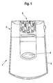
- Fig. 1 shows an embodiment of an epilating device 1 according to the invention in side view.
- the epilating device 1 has a housing 2 and an epilation head 3 removably attached to the housing 2.
- the housing 2 is shaped so that it can be comfortably held in the hand.
- a switch 4 for switching on and off of the epilation device 1 is arranged on the housing 2.
- a rotary cylinder 5 is rotatably suspended in the epilation head 3.
- Fig. 2 shows an embodiment of the rotary cylinder 5 in a perspective view.
- the section marked with a circle is in Fig. 3 shown in enlarged form.
- the rotary cylinder 5 is rotatably supported in the epilation head 3 by means of a shaft 6.
- a gear 7 In the region of the axial ends of the rotary cylinder 5 is ever a gear 7 rotatably connected to the rotary cylinder 5.
- the rotary cylinder 5 of a non-figuratively illustrated electric motor inside the in Fig. 1 imaged housing 2 are driven.
- the rotary cylinder 5 is stacked in the axial direction of a plurality of components.
- clamping devices 8 which are embedded in support disks 9 and each have a first clamping element 10 and a second clamping element 11 will be discussed in more detail.
- Fig. 3 shows an enlarged section Fig. 2 in the region of one of the clamping devices 8.
- the first clamping elements 10 are suspended in the rotary cylinder 5 so that they each tilted relative to the shaft 6 and thereby the associated second clamping elements 11 can be axially approximated or removed from them.
- the second clamping elements 11 are arranged stationarily within the rotary cylinder 5 and perform relative to the rotary cylinder 5 no movement.
- the second clamping elements 11 can be formed integrally with the carrier disks 9
- the clamping devices 8 can thus be closed and opened by the movement of the first clamping elements 10.
- the first clamping elements 10 each have a first contact surface 12 and the second clamping elements 11 each have a second contact surface 13.
- a closed clamping device 8 In a closed clamping device 8, the first contact surface 12 of the first clamping member 10 and the second contact surface 13 of the second clamping member 11 are pressed against each other.
- the first clamping element 10 In the presentation of the Fig. 3 is the first clamping element 10 at a maximum distance from the associated second clamping element 11, so that the clamping device 8 is fully open.
- each clamping device 8 is correlated to the rotational movement of the rotary cylinder 5 periodically closed and opened by a tilting movement of the respective first clamping element 10.
- the clamping means 8 are moved along with the clamped hairs and plucked the hair out of the skin. Subsequently, the clamping devices 8 are opened again, so that the plucked hairs are released. It is also possible to actuate the clamping element 11 against a fixed clamping element 10 or the operation of both clamping elements 10 and 11th
- a respective clamping structure 14 is formed in the region of the first contact surfaces 12 of the first clamping elements 10, which has a multiplicity of parallel elevations 15.
- the elevations 15 have a substantially triangular cross section and extend transversely to the radial direction of the rotary cylinder 5 over the entire width of the respective first clamping element 10.
- the elevations 15 also have a different cross-section.
- the clamping structure 14 has a different overall topography.
- stochastic roughness structures are also possible. Regular structures can be generated for example by a stamping process. For the production of stochastic structures, in particular a sandblasting method can be used.
- the second clamping elements 11 in the region of their second contact surfaces 13 each have a lower hardness than the first clamping elements 10 in the region of their first contact surfaces 12.
- the action of the clamping structure 14 is partially cushioned on the hair. Due to the hardness of the first clamping elements 10 in the region of their first contact surfaces 12, the raised structural elements of the clamping structure 14 each form with time in the softer second contact surfaces 13 of the second clamping elements 11 a.
- the first clamping elements 10 may be made of metal, for example, and the second clamping elements 11 made of plastic.
- the clamping structure 14 is matched to the surface structure of the hair.
- the clamping structure 14 is formed so that it can engage in the scale-like surface structure of the hair.
- the clamping structure 14 has a mean roughness Ra of less than 2 ⁇ m, preferably less than 1 ⁇ m.
- the average roughness Ra is defined as the arithmetic mean of all deviations of the surface structure from a centerline extending transversely through the clamp structure 14.
- the average roughness depth Rz of the clamping structure 14, which represents the arithmetic mean of five individual roughness depths of five adjacent individual measuring sections, is less than 10 ⁇ m, preferably less than 6 ⁇ m.
- the maximum roughness depth Rmax of the clamping structure 14 is between 2 ⁇ m and 10 ⁇ m and indicates the largest single roughness depth within the entire measuring path. Values below 100 ⁇ m, in particular below 45 ⁇ m, are used for the mean distance RSM between the raised structural elements of the clamping structure 14. A detailed definition of the mean distance RSM can be found in the standard DIN EN ISO 4287 or ASME B46.1. The roughness values apply regardless of the orientation on the corresponding surface.
- clamping devices 8 In addition to the illustrated embodiment of the clamping devices 8, a large number of modifications is possible within the scope of the invention. For example, it is possible, instead of the first clamping element 10, to arrange the second clamping element 11 movably in the rotary cylinder 5. Likewise, in each case both clamping elements 10 and 11 are movably arranged in the rotary cylinder 5.
Landscapes
- Surgical Instruments (AREA)
- Supply, Installation And Extraction Of Printed Sheets Or Plates (AREA)
- Hair Curling (AREA)
- Dry Shavers And Clippers (AREA)
- Scissors And Nippers (AREA)
- Harvester Elements (AREA)
- Finger-Pressure Massage (AREA)
Description
- Die Erfindung bezieht sich auf eine Klemmeinrichtung für ein motorisch angetriebenes Epilationsgerät, insbesondere zum Auszupfen von Haaren der menschlichen Haut. Weiterhin bezieht sich die Erfindung auf einen Epilationskopf für ein Epilationsgerät und auf ein Epilationsgerät.
- Epilationsgeräte dienen dazu, Haare möglichst inklusive ihrer Wurzeln zu entfernen. Bekannte Epilationsgeräte sind beispielsweise so ausgebildet, daß die Haare zwischen benachbarten Klemmelementen geklemmt und durch eine Bewegung der Klemmelemente relativ zu der Haut ausgezupft werden. Für ein zuverlässiges Auszupfen und eine insgesamt möglichst schmerzarme Anwendung des Epilationsgeräts ist es erforderlich, daß die Haare fest zwischen den Klemmelementen geklemmt werden. Dies kann dadurch erreicht werden, daß die Klemmelemente mit einem hohen Anpreßdruck gegeneinander gepreßt werden. Allerdings ist der mit einem vertretbaren Aufwand erzeugbare Anpreßdruck begrenzt. Außerdem nimmt die Geräuschentwicklung des Epilationsgeräts mit steigendem Anpreßdruck zu und es steigt das Risiko, die Haare durch das Anpressen der Klemmelemente so stark zu beschädigen, daß sie während des Zupfvorgangs abreißen und somit nicht oder nicht vollständig ausgezupft werden.
- Weitere Maßnahmen, durch die ein zuverlässiges Klemmen der Haare während des Zupfvorgangs erreicht werden soll, sind aus der
US-PS 5 041 123 und derUS-PS 4 575 902 bekannt. - Die
US-PS 5 041 123 offenbart ein Epilationsgerät, das eine Reihe von Scheiben aufweist, die in paralleler Anordnung auf einer Nabe fixiert sind. Zwischen den Scheiben sind dünne Plättchen angeordnet, die jeweils gegen den Randbereich der benachbarten Scheibe gepreßt werden können. Um dabei die Haare zuverlässig zu klemmen, kann die Kontaktfläche zwischen den Scheiben und den Plättchen mit einer Rauheit versehen werden. - Aus der
US-PS 4 575 902 ist ein Epilationsgerät mit einer Reihe eng benachbarter Scheiben bekannt, die zusammen eine drehbare Rolle ausbilden. Während ihrer Rotation werden die Scheiben jeweils so verformt, daß benachbarte Scheiben gegeneinander gepreßt werden und dabei Haare zwischen den Scheiben geklemmt und durch die Rotationsbewegung ausgezupft werden. Um zu verhindern, daß die geklemmten Haare wieder herausrutschen, können die Scheiben einer Oberflächenrauheits-Behandlung unterzogen werden. Ebenso ist es auch möglich, Riefen oder sonstige Vertiefungen oder Erhöhungen auf den Oberflächen der Scheiben auszubilden. - Beim Einsatz von Klemmelementen mit einer aufgerauhten Oberfläche oder einer Oberfläche, die Riefen bzw. sonstige Erhebungen oder Vertiefungen aufweist, läßt sich das Risiko eines Entgleitens der Haare aus den geschlossenen Klemmelementen reduzieren. Je nach Ausbildung der Oberfläche der Klemmelemente kann sich der Anteil an abgerissenen Haaren aber sogar erhöhen, da insbesondere eine Oberfläche mit scharfkantigen Strukturen zu einer verstärkten Beschädigung der geklemmten Haare führen kann.
- Der Erfindung liegt die Aufgabe zugrunde, bei einem motorisch angetriebenen Epilationsgerät mit einem vertretbaren Aufwand ein zuverlässiges Klemmen der Haare sicherzustellen und dabei durch das Klemmen verursachte Beschädigungen der Haare möglichst gering zu halten.
- Diese Aufgabe wird durch die Merkmalskombination des Anspruchs 1 gelöst.
- Die erfindungsgemäße Klemmeinrichtung für ein motorisch angetriebenes Epilationsgerät, insbesondere zum Auszupfen von Haaren der menschlichen Haut, weist ein erstes Klemmelement mit einer ersten Kontaktfläche auf, in deren Bereich eine dreidimensionale Klemmstruktur ausgebildet ist. Weiterhin weist die erfindungsgemäße Klemmeinrichtung ein zweites Klemmelement mit einer zweiten Kontaktfläche auf. Die Kontaktflächen der Klemmelemente stehen beim Betrieb des Epilationsgeräts zeitweise in einem Klemmkontakt zueinander. Die Besonderheit der erfindungsgemäßen Klemmeinrichtung besteht darin, daß das zweite Klemmelement im Bereich der zweiten Kontaktfläche eine geringere Härte aufweist als das erste Klemmelement im Bereich der ersten Kontaktfläche.
- Die Erfindung hat den Vorteil, daß sie auf schonende Weise ein zuverlässiges Klemmen der Haare ermöglicht. Dabei ist das Risiko des Entgleitens der Haare aus der geschlossenen Klemmeinrichtung vergleichsweise gering. Auch das Risiko, daß die geklemmten Haare so stark beschädigt werden, daß sie abreißen, ist sehr gering. Dies bedeutet, daß unnötige Schmerzereignisse bei der Anwendung des Epilationsgeräts, die nicht zu einem Auszupfen von Haaren führen, weitgehend vermieden werden können. Ein weiterer Vorteil besteht darin, daß ein zuverlässiges Klemmen der Haare mit einem reduzierten Anpreßdruck der Kontaktflächen gegeneinander möglich ist. Dies führt zum einen zu einer verminderten Geräuschentwicklung bei der Ausbildung des Klemmkontakts und zum anderen zu einer geringeren Beanspruchung der einzelnen Komponenten und damit zu einem geringeren Materialverschleiß. Die weiche zweite Kontaktfläche wirkt zudem geräuschdämmend und vibrationsmindernd.
- Der Härteunterschied zwischen den Kontaktflächen der Klemmelemente ist so groß, daß die Klemmstruktur bei der Ausbildung des Klemmkontakts wenigstens temporär und/oder partiell in die zweite Kontaktfläche des zweiten Klemmelements eingeformt wird. Dadurch wird die Klemmwirkung unterstützt und zudem vermieden, daß die, Klemmstruktur das Schließen der Klemmeinrichtung behindert.
- Das zweite Klemmelement weist im Bereich der zweiten Kontaktfläche bevorzugt einen kleineren Mittenrauhwert Ra als das erste Klemmelement im Bereich der ersten Kontaktfläche auf. Weiterhin ist vorzugsweise das erste Klemmelement derart beweglich angeordnet, daß der Abstand zwischen den Kontaktflächen der Klemmelemente variierbar ist. Dies bedeutet, daß das Öffnen und Schließen der Klemmeinrichtung bevorzugt mit Hilfe des ersten Klemmelements erfolgt, das auch die Klemmstruktur aufweist.
- Die Klemmstruktur kann beispielsweise als eine stochastische Rauheitsstruktur ausgebildet sein. Eine derartige Struktur läßt sich kostengünstig herstellen. Alternativ dazu ist es auch möglich, die Klemmstruktur als eine geordnete geometrische Struktur, insbesondere in Form von parallel zueinander verlaufenden Erhebungen oder Vertiefungen, ausgebildet ist. Dies hat den Vorteil, daß sich das Klemmverhalten der Klemmeinrichtung sehr gezielt beeinflussen läßt.
- Die Klemmeinrichtung wird vorzugsweise so ausgebildet, daß die Klemmstruktur einen Mittenrauhwert Ra aufweist, der kleiner als 2 µm, insbesondere kleiner als 1 µm, ist. Weiterhin ist es von Vorteil, wenn die Klemmstruktur eine gemittelte Rauhtiefe Rz aufweist, die kleiner als 10 µm, insbesondere kleiner als 6 µm, ist. Die maximale Rauhtiefe Rmax der Klemmstruktur kann zwischen 2 µm und 10 µm betragen. Als mittlerer Abstand RSM zwischen benachbarten Erhebungen oder Vertiefungen werden bei der Klemmstruktur Werte bevorzugt, die kleiner als 100 µm, insbesondere kleiner als 45 µm, sind.
- Das erste Klemmelement kann im Bereich der ersten Kontaktfläche aus Metall gefertigt sein. Das zweite Klemmelement ist im Bereich der zweiten Kontaktfläche vorzugsweise aus Kunststoff gefertigt.
- Die Erfindung bezieht sich weiterhin auf einen Epilationskopf, der wenigstens eine erfindungsgemäße Klemmeinrichtung aufweist.
- Schließlich bezieht sich die Erfindung noch auf ein Epilationsgerät, mit einem in der Hand haltbaren Gehäuse und einem derartigen Epilationskopf.
- Die Erfindung wird nachstehend anhand der in der Zeichnung dargestellten Ausführungsbeispiele näher erläutert.
- Es zeigen:
- Fig. 1
- ein Ausführungsbeispiel eines erfindungsgemäß ausgebildeten Epilationsgeräts in Seitenansicht,
- Fig. 2
- ein Ausführungsbeispiel für den Drehzylinder des erfindungsgemäßen Epilationsge- räts in perspektivischer Darstellung und
- Fig. 3
- einen vergrößerten Ausschnitt aus
Fig. 2 im Bereich einer der erfindungsgemäßen Klemmeinrichtungen. -
Fig. 1 zeigt ein Ausführungsbeispiel eines Epilationsgeräts 1 gemäß der Erfindung in Seitenansicht. Das Epilationsgerät 1 weist ein Gehäuse 2 und einen abnehmbar am Gehäuse 2 befestigten Epilationskopf 3 auf. Das Gehäuse 2 ist so geformt, daß es bequem in der Hand gehalten werden kann. Am Gehäuse 2 ist ein Schalter 4 zum Ein- und Ausschalten des Epilationsgeräts 1 angeordnet. Im Epilationskopf 3 ist ein Drehzylinder 5 drehbar aufgehängt. -
Fig. 2 zeigt ein Ausführungsbeispiel für den Drehzylinder 5 in perspektivischer Darstellung. Der mit einem Kreis gekennzeichnete Ausschnitt ist inFig. 3 in vergrößerter Form dargestellt. Der Drehzylinder 5 ist mittels einer Welle 6 drehbar im Epilationskopf 3 gelagert. Im Bereich der axialen Enden des Drehzylinders 5 ist je ein Zahnrad 7 drehfest mit dem Drehzylinder 5 verbunden. Über die Zahnräder 7 kann der Drehzylinder 5 von einem nicht figürlich dargestellten Elektromotor im Inneren des inFig. 1 abgebildeten Gehäuses 2 angetrieben werden. Der Drehzylinder 5 ist in Axialrichtung aus einer Vielzahl von Komponenten stapelförmig zusammengesetzt. Im folgenden wird lediglich auf Klemmeinrichtungen 8 näher eingegangen, die in Trägerscheiben 9 eingebettet sind und jeweils ein erstes Klemmelement 10 und ein zweites Klemmelement 11 aufweisen. -
Fig. 3 zeigt einen vergrößerten Ausschnitt ausFig. 2 im Bereich einer der Klemmeinrichtungen 8. Die ersten Klemmelemente 10 sind so im Drehzylinder 5 aufgehängt, daß sie jeweils relativ zur Welle 6 gekippt und dadurch den zugehörigen zweiten Klemmelementen 11 axial angenähert bzw. von diesen entfernt werden können. Die zweiten Klemmelemente 11 sind innerhalb des Drehzylinders 5 ortsfest angeordnet und führen relativ zum Drehzylinder 5 keine Bewegung aus. Insbesondere können die zweiten Klemmelemente 11 einteilig mit den Trägerscheiben 9 ausgebildet sein Die Klemmeinrichtungen 8 können somit durch die Bewegung der ersten Klemmelemente 10 geschlossen und geöffnet werden. Zum Klemmen der Haare weisen die ersten Klemmelemente 10 jeweils eine erste Kontaktfläche 12 und die zweiten Klemmelemente 11 jeweils eine zweite Kontaktfläche 13 auf. Bei einer geschlossenen Klemmeinrichtung 8 werden die erste Kontaktfläche 12 des ersten Klemmelements 10 und die zweite Kontaktfläche 13 des zweiten Klemmelements 11 gegeneinander gepreßt. In der Darstellung derFig. 3 befindet sich das erste Klemmelement 10 in maximaler Entfernung vom zugehörigen zweiten Klemmelement 11, so daß die Klemmeinrichtung 8 vollständig geöffnet ist. - Beim Betrieb des Epilationsgeräts 1 wird der Drehzylinder 5 in Rotation versetzt, wobei sämtliche Klemmeinrichtungen 8 des Drehzylinders 5 zusammen mit diesem rotieren. Dabei wird jede Klemmeinrichtung 8 korreliert zur Drehbewegung des Drehzylinders 5 durch eine Kippbewegung des jeweiligen ersten Klemmelements 10 periodisch geschlossen und geöffnet. Beim Schließen der Klemmeinrichtungen 8 werden die im Bereich zwischen den Kontaktflächen 12 und 13 der Klemmelemente 10 und 11 angeordneten Haare geklemmt und dadurch an den jeweiligen Klemmeinrichtungen 8 fixiert. Durch die Rotationsbewegung des Drehzylinders 5 werden die Klemmeinrichtungen 8 zusammen mit den geklemmten Haaren weiterbewegt und die Haare dabei aus der Haut ausgezupft. Anschließend werden die Klemmeinrichtungen 8 wieder geöffnet, so daß die ausgezupften Haare freigegeben werden. Möglich ist auch eine Betätigung des Klemmelementes 11 gegen ein feststehendes Klemmelement 10 oder die Betätigung beider Klemmelemente 10 und 11.
- Um ein Herausrutschen der Haare während des Zupfvorganges aus den geschlossenen Klemmeinrichtungen 8 zu vermeiden, ist im Bereich der ersten Kontaktflächen 12 der ersten Klemmelemente 10 jeweils eine Klemmstruktur 14. ausgebildet, die eine Vielzahl von parallel verlaufenden Erhebungen 15 aufweist. Die Erhebungen 15 weisen einen im wesentlichen dreieckigen Querschnitt auf und erstrecken sich quer zur Radialrichtung des Drehzylinders 5 über die gesamte Breite des jeweiligen ersten Klemmelements 10. Alternativ dazu können die Erhebungen 15 auch einen anderen Querschnitt aufweisen. Ebenso besteht auch die Möglichkeit, daß die Klemmstruktur 14 insgesamt eine andersartige Topographie aufweist. Dabei sind neben regelmäßig ausgebildeten Strukturen auch stochastisch ausgebildete Rauheitsstrukturen möglich. Regelmäßige Strukturen können beispielsweise durch ein Prägeverfahren erzeugt werden. Zur Herstellung von stochastischen Strukturen kann insbesondere ein Sandstrahlverfahren eingesetzt werden.
- Eine übermäßige Beschädigung der Haare beim Klemmen mit den Klemmelementen 10 und 11 wird im Rahmen der Erfindung dadurch vermieden; daß die zweiten Klemmelemente 11 im Bereich ihrer zweiten Kontaktflächen 13 jeweils eine geringere Härte aufweisen als die ersten Klemmelemente 10 im Bereich ihrer ersten Kontaktflächen 12. Dadurch wird die Einwirkung der Klemmstruktur 14 auf die Haare zum Teil abgefedert. Aufgrund der Härte der ersten Klemmelemente 10 im Bereich ihrer ersten Kontaktflächen 12, formen sich die erhabenen Strukturelemente der Klemmstruktur 14 jeweils mit der Zeit in die weicheren zweiten Kontaktflächen 13 der zweiten Klemmelemente 11 ein. Die ersten Klemmelemente 10 können beispielsweise aus Metall und die zweite Klemmelemente 11 aus Kunststoff gefertigt sein.
- Zur Erzielung einer guten Klemmwirkung ist die Klemmstruktur 14 auf die Oberflächenstruktur der Haare abgestimmt. Insbesondere ist die Klemmstruktur 14 so ausgebildet, daß sie in die schuppenartig ausgebildete Oberflächenstruktur der Haare eingreifen kann. Hierzu weist die Klemmstruktur 14 einen Mittenrauhwert Ra von weniger als 2 µm, vorzugsweise weniger als 1 µm, auf. Der Mittenrauhwert Ra ist als arithmetischer Mittelwert aller Abweichungen der Oberflächenstruktur von einer quer durch die Klemmstruktur 14 verlaufende Mittellinie definiert. Die gemittelte Rauhtiefe Rz der Klemmstruktur 14, die den arithmetischen Mittelwert aus fünf Einzelrauhtiefen fünf aneinander grenzender Einzelmeßstrecken darstellt, ist kleiner als 10 µm, vorzugsweise kleiner als 6 µm. Die maximale Rauhtiefe Rmax der Klemmstruktur 14 beträgt zwischen 2 µm und 10 µm und gibt die größte Einzelrauhtiefe innerhalb der gesamten Meßstrecke an. Für den mittleren Abstand RSM zwischen den erhabenen Strukturelementen der Klemmstruktur 14 kommen Werte unterhalb 100 µm, insbesondere unterhalb 45 µm, zur Anwendung. Eine detaillierte Definition des mittleren Abstands RSM findet sich in der Norm DIN EN ISO 4287 bzw. ASME B46.1. Die Rauhigkeitswerte gelten dabei unabhängig von der Ausrichtung auf der entsprechenden Oberfläche.
- Innerhalb der genannten Bereiche für die Rauheitskenngrößen ist weitgehend sichergestellt, daß die Klemmstruktur 14 einerseits genügend griffig ist, um die Haare zuverlässig zu fixieren und andererseits nicht so scharfkantig ist, daß sie die Haare beim Klemmen in einem Ausmaß beschädigt, welches einen Abriß der Haare zur Folge hat. Ein optimales Ergebnis wird erzielt, wenn sämtliche Rauheitskenngrößen innerhalb der angegebenen Bereiche liegen. Es ist aber auch möglich, mit einer Rauheitskenngröße oder mit mehreren Rauheitskenngrößen von den angegebenen Bereichen abzuweichen.
- Neben der dargestellten Ausbildung der Klemmeinrichtungen 8 ist im Rahmen der Erfindung eine Vielzahl von Abwandlungen möglich. Beispielsweise besteht die Möglichkeit, jeweils anstelle des ersten Klemmelements 10 das zweite Klemmelement 11 beweglich im Drehzylinder 5 anzuordnen. Ebenso können jeweils auch beide Klemmelemente 10 und 11 beweglich im Drehzylinder 5 angeordnet werden.
Claims (13)
- Klemmeinrichtung für ein motorisch angetriebenes Epilationsgerät (1), insbesondere zum Auszupfen von Haaren der menschlichen Haut, mit einem ersten Klemmelement (10), das eine erste Kontaktfläche (12) aufweist, in deren Bereich eine dreidimensionale Klemmstruktur (14) ausgebildet ist und einem zweiten Klemmelement (11), das eine zweite Kontaktfläche (13) aufweist, wobei die Kontaktflächen (12, 13) der Klemmelemente (10, 11) beim Betrieb des Epilationsgeräts (1) zeitweise in einem Klemmkontakt zueinander stehen und das zweite Klemmelement (11) im Bereich der zweiten Kontaktfläche (13) eine geringere Härte aufweist als das erste Klemmelement (10) im Bereich der ersten Kontaktfläche (12), dadurch gekennzeichnet, dass der Härteunterschied zwischen den Kontaktflächen (12, 13) der Klemmelemente (10, 11) so groß ist, dass die Klemmstruktur (14) bei der Ausbildung des Klemmkontakts wenigstens temporär und/oder partiell in die zweite Kontaktfläche (13) des zweiten Klemmelements (11) eingeformt wird.
- Klemmeinrichtung nach Anspruch 1, dadurch gekennzeichnet, dass das zweite Klemmelement (11) im Bereich der zweiten Kontaktfläche (13) einen kleineren Mittenrauhwert Ra als das erste Klemmelement (10) im Bereich der ersten Kontaktfläche (12) aufweist.
- Klemmeinrichtung nach einem der vorhergehenden Ansprüche, dadurch gekennzeichnet, dass das erste Klemmelement (10) derart beweglich angeordnet ist, dass der Abstand zwischen den Kontaktflächen (12, 13) der Klemmelemente (10, 11) variierbar ist.
- Klemmeinrichtung nach einem der vorhergehenden Ansprüche, dadurch gekennzeichnet, dass die Klemmstruktur (14) als eine stochastische Rauheitsstruktur ausgebildet ist.
- Klemmeinrichtung nach einem der Ansprüche 1 bis 3, dadurch gekennzeichnet, dass die Klemmstruktur (14) als eine geordnete geometrische Struktur, insbesondere in Form von parallel zueinander verlaufenden Erhebungen (15) oder Vertiefungen, ausgebildet ist.
- Klemmeinrichtung nach einem der vorhergehenden Ansprüche, dadurch gekennzeichnet, dass die Klemmstruktur (14) einen Mittenrauhwert Ra aufweist, der kleiner als 2 µm, insbesondere kleiner als 1 µm, ist.
- Klemmeinrichtung nach einem der vorhergehenden Ansprüche, dadurch gekennzeichnet, dass die Klemmstruktur (14) eine gemittelte Rauhtiefe Rz aufweist, die kleiner als 10 µm, insbesondere kleiner als 6 µm, ist.
- Klemmeinrichtung nach einem der vorhergehenden Ansprüche, dadurch gekennzeichnet, dass die Klemmstruktur (14) eine maximale Rauhtiefe Rmax aufweist, die zwischen 2 µm und 10 µm beträgt.
- Klemmeinrichtung nach einem der vorhergehenden Ansprüche, dadurch gekennzeichnet, dass die Klemmstruktur (14) einen mittleren Abstand RSM zwischen benachbarten Erhebungen (15) oder Vertiefungen aufweist, der kleiner als 100 µm, insbesondere kleiner als 45 µm, ist.
- Klemmeinrichtung nach einem der vorhergehenden Ansprüche, dadurch gekennzeichnet, dass das erste Klemmelement (10) im Bereich der ersten Kontaktfläche (12) aus Metall gefertigt ist.
- Klemmeinrichtung nach einem der vorhergehenden Ansprüche, dadurch gekennzeichnet, dass das zweite Klemmelement (11) im Bereich der zweiten Kontaktfläche (13) aus Kunststoff gefertigt ist.
- Epilationskopf für ein motorisch angetriebenes Epilationsgerät (1), insbesondere zum Auszupfen von Haaren der menschlichen Haut, mit wenigstens einer Klemmeinrichtung (8), dadurch gekennzeichnet, dass die Klemmeinrichtung (8) gemäß einem der vorhergehenden Ansprüche ausgebildet ist.
- Motorisch angetriebenes Epilationsgerät, insbesondere zum Auszupfen von Haaren der menschlichen Haut, mit einem in der Hand haltbaren Gehäuse (2) und einem Epilationskopf (3), dadurch gekennzeichnet, dass der Epilationskopf (3) gemäß Anspruch 12 ausgebildet ist.
Applications Claiming Priority (2)
| Application Number | Priority Date | Filing Date | Title |
|---|---|---|---|
| DE102004047875A DE102004047875A1 (de) | 2004-10-01 | 2004-10-01 | Klemmeinrichtung für ein Epilationsgerät |
| PCT/EP2005/008233 WO2006037393A1 (de) | 2004-10-01 | 2005-07-29 | Klemmeinrichtung für ein epilationsgerät |
Publications (2)
| Publication Number | Publication Date |
|---|---|
| EP1796500A1 EP1796500A1 (de) | 2007-06-20 |
| EP1796500B1 true EP1796500B1 (de) | 2009-10-07 |
Family
ID=35058623
Family Applications (1)
| Application Number | Title | Priority Date | Filing Date |
|---|---|---|---|
| EP05771856A Expired - Lifetime EP1796500B1 (de) | 2004-10-01 | 2005-07-29 | Klemmeinrichtung für ein epilationsgerät |
Country Status (7)
| Country | Link |
|---|---|
| US (1) | US8303603B2 (de) |
| EP (1) | EP1796500B1 (de) |
| AT (1) | ATE444688T1 (de) |
| DE (2) | DE102004047875A1 (de) |
| ES (1) | ES2333140T3 (de) |
| RU (1) | RU2372006C2 (de) |
| WO (1) | WO2006037393A1 (de) |
Families Citing this family (10)
| Publication number | Priority date | Publication date | Assignee | Title |
|---|---|---|---|---|
| DE102006027527A1 (de) * | 2006-06-14 | 2007-12-27 | Braun Gmbh | Haarentfernungsvorrichtung |
| DE102006043307A1 (de) * | 2006-09-14 | 2008-03-27 | Braun Gmbh | Verfahren zur kosmetischen Körperhaarentfernung sowie Haarentfernungsvorrichtung |
| DE602008005293D1 (de) * | 2008-07-17 | 2011-04-14 | Braun Gmbh | Haarentfernungsvorrichtung |
| JP4720887B2 (ja) * | 2008-09-22 | 2011-07-13 | パナソニック電工株式会社 | 脱毛装置 |
| ES2687266T3 (es) * | 2010-12-28 | 2018-10-24 | Braun Gmbh | Nuevo cabezal de pinzas para la depilación |
| EP2471405B1 (de) | 2010-12-28 | 2016-05-18 | Braun GmbH | Neuartige Pinzettenanordnung für einen Haarentfernungskopf |
| EP2471404B1 (de) * | 2010-12-28 | 2018-06-27 | Braun GmbH | Neuartige Pinzettenanordnung für einen Haarentfernungskopf |
| WO2014057471A2 (en) * | 2012-10-12 | 2014-04-17 | Braun Gmbh | Epilator |
| ES2634415T3 (es) * | 2013-04-16 | 2017-09-27 | Braun Gmbh | Accesorio para depiladora y depiladora |
| EP3915430A1 (de) * | 2020-05-26 | 2021-12-01 | Koninklijke Philips N.V. | Verbesserung derhaarklemmleistung von einem paar haarklemmenelementen |
Family Cites Families (8)
| Publication number | Priority date | Publication date | Assignee | Title |
|---|---|---|---|---|
| US3735765A (en) * | 1971-03-18 | 1973-05-29 | D Ichelson | Method of closing lacerations and clamp therefor |
| FR2556939B1 (fr) * | 1983-12-22 | 1987-10-23 | Jean Alazet | Appareil a epiler |
| IL86447A (en) * | 1988-05-19 | 1994-04-12 | Yahav Shimon | Electrically powered depilatory device |
| FR2648332B1 (fr) * | 1989-06-16 | 1991-11-29 | Seb Sa | Appareil a epiler |
| FR2684858B1 (fr) * | 1991-12-17 | 1996-06-07 | Braun Ag | Appareil d'epilation a elements de serrage et contre-appuis. |
| DE19823577A1 (de) * | 1998-05-27 | 2000-03-02 | Braun Gmbh | Drehzylinder für ein Epilationsgerät |
| EP1013191A1 (de) * | 1998-12-18 | 2000-06-28 | Patrick Langohr | Haarspange |
| US20040167544A1 (en) * | 2002-12-13 | 2004-08-26 | Eveready Battery Company, Inc. | Progressive hair removal surface |
-
2004
- 2004-10-01 DE DE102004047875A patent/DE102004047875A1/de not_active Withdrawn
-
2005
- 2005-07-29 AT AT05771856T patent/ATE444688T1/de not_active IP Right Cessation
- 2005-07-29 RU RU2007116137/12A patent/RU2372006C2/ru not_active IP Right Cessation
- 2005-07-29 WO PCT/EP2005/008233 patent/WO2006037393A1/de not_active Ceased
- 2005-07-29 DE DE502005008292T patent/DE502005008292D1/de not_active Expired - Lifetime
- 2005-07-29 EP EP05771856A patent/EP1796500B1/de not_active Expired - Lifetime
- 2005-07-29 US US11/576,120 patent/US8303603B2/en not_active Expired - Fee Related
- 2005-07-29 ES ES05771856T patent/ES2333140T3/es not_active Expired - Lifetime
Also Published As
| Publication number | Publication date |
|---|---|
| RU2007116137A (ru) | 2008-11-10 |
| ES2333140T3 (es) | 2010-02-17 |
| DE102004047875A1 (de) | 2006-04-20 |
| DE502005008292D1 (de) | 2009-11-19 |
| WO2006037393A1 (de) | 2006-04-13 |
| US8303603B2 (en) | 2012-11-06 |
| EP1796500A1 (de) | 2007-06-20 |
| ATE444688T1 (de) | 2009-10-15 |
| RU2372006C2 (ru) | 2009-11-10 |
| US20070212923A1 (en) | 2007-09-13 |
Similar Documents
| Publication | Publication Date | Title |
|---|---|---|
| DE68928647T2 (de) | Enthaarungsgerät | |
| DE69927618T2 (de) | Scheibenenthaarungsvorrichtung | |
| DE68908070T2 (de) | Gerät zum Enthaaren. | |
| EP3765201B1 (de) | Rotor eines zentrifugalabscheiders und zentrifugalabscheider | |
| DE3930884C2 (de) | ||
| DE4427788C2 (de) | Epilationsgerät zum Entfernen von Haaren am menschlichen Körper | |
| EP0510248A2 (de) | Epilationsgerät | |
| DE102009015432A1 (de) | Oberflächenstruktur für ein Arbeitsgerät | |
| DE102004047875A1 (de) | Klemmeinrichtung für ein Epilationsgerät | |
| DE69821807T2 (de) | Haarentfernungsgerät mit drehbarer Rolle | |
| DE69200912T2 (de) | Scheibenepiliergerät mit spielfreier Achsenkupplung. | |
| EP1256287B1 (de) | Drehzylinder für ein Epilationsgerät | |
| EP0547386B1 (de) | Epilationsgerät | |
| DE60128214T2 (de) | Rotor, rotoranordnung, verfahren und vorrichtung zur herstellung eines rotorelements | |
| EP1796499B1 (de) | Epilationskopf und epilationsgerät | |
| DE602004002929T2 (de) | Schneidkopf für buschmäher, kantentrimmer oder dergleichen | |
| DE4414219C2 (de) | Rotor für eine elektrische Maschine | |
| WO2023165734A1 (de) | Vorrichtung zum schleifen von borstenfilamenten und bürstenherstellungsmaschine mit einer solchen vorrichtung | |
| DE10108416A1 (de) | Stützscheibengrundkörper zur Lagerung eines Offenend-Spinnrotors | |
| DE4319469A1 (de) | Schaufelrad und Gerät zu dessen Herstellung | |
| DE102012012624A1 (de) | Verbindung von Läuferpaket und Läuferwelle an einer elektrischen Maschine | |
| DE102004052448A1 (de) | Epiliergerät | |
| EP1867247A2 (de) | Haarentfernungsvorrichtung | |
| EP1521538A1 (de) | Epilationsgerät | |
| DE29902951U1 (de) | Epilieraufsatz |
Legal Events
| Date | Code | Title | Description |
|---|---|---|---|
| PUAI | Public reference made under article 153(3) epc to a published international application that has entered the european phase |
Free format text: ORIGINAL CODE: 0009012 |
|
| 17P | Request for examination filed |
Effective date: 20070227 |
|
| AK | Designated contracting states |
Kind code of ref document: A1 Designated state(s): AT BE BG CH CY CZ DE DK EE ES FI FR GB GR HU IE IS IT LI LT LU LV MC NL PL PT RO SE SI SK TR |
|
| DAX | Request for extension of the european patent (deleted) | ||
| 17Q | First examination report despatched |
Effective date: 20080905 |
|
| GRAP | Despatch of communication of intention to grant a patent |
Free format text: ORIGINAL CODE: EPIDOSNIGR1 |
|
| GRAS | Grant fee paid |
Free format text: ORIGINAL CODE: EPIDOSNIGR3 |
|
| GRAA | (expected) grant |
Free format text: ORIGINAL CODE: 0009210 |
|
| AK | Designated contracting states |
Kind code of ref document: B1 Designated state(s): AT BE BG CH CY CZ DE DK EE ES FI FR GB GR HU IE IS IT LI LT LU LV MC NL PL PT RO SE SI SK TR |
|
| REG | Reference to a national code |
Ref country code: GB Ref legal event code: FG4D Free format text: NOT ENGLISH |
|
| REG | Reference to a national code |
Ref country code: CH Ref legal event code: EP |
|
| REG | Reference to a national code |
Ref country code: IE Ref legal event code: FG4D |
|
| REF | Corresponds to: |
Ref document number: 502005008292 Country of ref document: DE Date of ref document: 20091119 Kind code of ref document: P |
|
| REG | Reference to a national code |
Ref country code: ES Ref legal event code: FG2A Ref document number: 2333140 Country of ref document: ES Kind code of ref document: T3 |
|
| PG25 | Lapsed in a contracting state [announced via postgrant information from national office to epo] |
Ref country code: SI Free format text: LAPSE BECAUSE OF FAILURE TO SUBMIT A TRANSLATION OF THE DESCRIPTION OR TO PAY THE FEE WITHIN THE PRESCRIBED TIME-LIMIT Effective date: 20091007 |
|
| LTIE | Lt: invalidation of european patent or patent extension |
Effective date: 20091007 |
|
| PG25 | Lapsed in a contracting state [announced via postgrant information from national office to epo] |
Ref country code: FI Free format text: LAPSE BECAUSE OF FAILURE TO SUBMIT A TRANSLATION OF THE DESCRIPTION OR TO PAY THE FEE WITHIN THE PRESCRIBED TIME-LIMIT Effective date: 20091007 Ref country code: LT Free format text: LAPSE BECAUSE OF FAILURE TO SUBMIT A TRANSLATION OF THE DESCRIPTION OR TO PAY THE FEE WITHIN THE PRESCRIBED TIME-LIMIT Effective date: 20091007 Ref country code: PT Free format text: LAPSE BECAUSE OF FAILURE TO SUBMIT A TRANSLATION OF THE DESCRIPTION OR TO PAY THE FEE WITHIN THE PRESCRIBED TIME-LIMIT Effective date: 20100208 Ref country code: IS Free format text: LAPSE BECAUSE OF FAILURE TO SUBMIT A TRANSLATION OF THE DESCRIPTION OR TO PAY THE FEE WITHIN THE PRESCRIBED TIME-LIMIT Effective date: 20100207 Ref country code: SE Free format text: LAPSE BECAUSE OF FAILURE TO SUBMIT A TRANSLATION OF THE DESCRIPTION OR TO PAY THE FEE WITHIN THE PRESCRIBED TIME-LIMIT Effective date: 20091007 |
|
| REG | Reference to a national code |
Ref country code: IE Ref legal event code: FD4D |
|
| PG25 | Lapsed in a contracting state [announced via postgrant information from national office to epo] |
Ref country code: LV Free format text: LAPSE BECAUSE OF FAILURE TO SUBMIT A TRANSLATION OF THE DESCRIPTION OR TO PAY THE FEE WITHIN THE PRESCRIBED TIME-LIMIT Effective date: 20091007 Ref country code: PL Free format text: LAPSE BECAUSE OF FAILURE TO SUBMIT A TRANSLATION OF THE DESCRIPTION OR TO PAY THE FEE WITHIN THE PRESCRIBED TIME-LIMIT Effective date: 20091007 |
|
| PG25 | Lapsed in a contracting state [announced via postgrant information from national office to epo] |
Ref country code: BG Free format text: LAPSE BECAUSE OF FAILURE TO SUBMIT A TRANSLATION OF THE DESCRIPTION OR TO PAY THE FEE WITHIN THE PRESCRIBED TIME-LIMIT Effective date: 20100107 Ref country code: IE Free format text: LAPSE BECAUSE OF FAILURE TO SUBMIT A TRANSLATION OF THE DESCRIPTION OR TO PAY THE FEE WITHIN THE PRESCRIBED TIME-LIMIT Effective date: 20091007 Ref country code: EE Free format text: LAPSE BECAUSE OF FAILURE TO SUBMIT A TRANSLATION OF THE DESCRIPTION OR TO PAY THE FEE WITHIN THE PRESCRIBED TIME-LIMIT Effective date: 20091007 Ref country code: DK Free format text: LAPSE BECAUSE OF FAILURE TO SUBMIT A TRANSLATION OF THE DESCRIPTION OR TO PAY THE FEE WITHIN THE PRESCRIBED TIME-LIMIT Effective date: 20091007 Ref country code: RO Free format text: LAPSE BECAUSE OF FAILURE TO SUBMIT A TRANSLATION OF THE DESCRIPTION OR TO PAY THE FEE WITHIN THE PRESCRIBED TIME-LIMIT Effective date: 20091007 |
|
| PLBE | No opposition filed within time limit |
Free format text: ORIGINAL CODE: 0009261 |
|
| STAA | Information on the status of an ep patent application or granted ep patent |
Free format text: STATUS: NO OPPOSITION FILED WITHIN TIME LIMIT |
|
| PG25 | Lapsed in a contracting state [announced via postgrant information from national office to epo] |
Ref country code: CZ Free format text: LAPSE BECAUSE OF FAILURE TO SUBMIT A TRANSLATION OF THE DESCRIPTION OR TO PAY THE FEE WITHIN THE PRESCRIBED TIME-LIMIT Effective date: 20091007 Ref country code: SK Free format text: LAPSE BECAUSE OF FAILURE TO SUBMIT A TRANSLATION OF THE DESCRIPTION OR TO PAY THE FEE WITHIN THE PRESCRIBED TIME-LIMIT Effective date: 20091007 |
|
| 26N | No opposition filed |
Effective date: 20100708 |
|
| PG25 | Lapsed in a contracting state [announced via postgrant information from national office to epo] |
Ref country code: GR Free format text: LAPSE BECAUSE OF FAILURE TO SUBMIT A TRANSLATION OF THE DESCRIPTION OR TO PAY THE FEE WITHIN THE PRESCRIBED TIME-LIMIT Effective date: 20100108 |
|
| BERE | Be: lapsed |
Owner name: BRAUN G.M.B.H. Effective date: 20100731 |
|
| PG25 | Lapsed in a contracting state [announced via postgrant information from national office to epo] |
Ref country code: MC Free format text: LAPSE BECAUSE OF NON-PAYMENT OF DUE FEES Effective date: 20100731 |
|
| REG | Reference to a national code |
Ref country code: CH Ref legal event code: PL |
|
| PG25 | Lapsed in a contracting state [announced via postgrant information from national office to epo] |
Ref country code: IT Free format text: LAPSE BECAUSE OF FAILURE TO SUBMIT A TRANSLATION OF THE DESCRIPTION OR TO PAY THE FEE WITHIN THE PRESCRIBED TIME-LIMIT Effective date: 20091007 |
|
| PG25 | Lapsed in a contracting state [announced via postgrant information from national office to epo] |
Ref country code: CH Free format text: LAPSE BECAUSE OF NON-PAYMENT OF DUE FEES Effective date: 20100731 Ref country code: LI Free format text: LAPSE BECAUSE OF NON-PAYMENT OF DUE FEES Effective date: 20100731 |
|
| PG25 | Lapsed in a contracting state [announced via postgrant information from national office to epo] |
Ref country code: BE Free format text: LAPSE BECAUSE OF NON-PAYMENT OF DUE FEES Effective date: 20100731 |
|
| PG25 | Lapsed in a contracting state [announced via postgrant information from national office to epo] |
Ref country code: AT Free format text: LAPSE BECAUSE OF NON-PAYMENT OF DUE FEES Effective date: 20100729 |
|
| PG25 | Lapsed in a contracting state [announced via postgrant information from national office to epo] |
Ref country code: CY Free format text: LAPSE BECAUSE OF FAILURE TO SUBMIT A TRANSLATION OF THE DESCRIPTION OR TO PAY THE FEE WITHIN THE PRESCRIBED TIME-LIMIT Effective date: 20091007 |
|
| PG25 | Lapsed in a contracting state [announced via postgrant information from national office to epo] |
Ref country code: LU Free format text: LAPSE BECAUSE OF NON-PAYMENT OF DUE FEES Effective date: 20100729 Ref country code: HU Free format text: LAPSE BECAUSE OF FAILURE TO SUBMIT A TRANSLATION OF THE DESCRIPTION OR TO PAY THE FEE WITHIN THE PRESCRIBED TIME-LIMIT Effective date: 20100408 |
|
| REG | Reference to a national code |
Ref country code: FR Ref legal event code: PLFP Year of fee payment: 11 |
|
| REG | Reference to a national code |
Ref country code: FR Ref legal event code: PLFP Year of fee payment: 12 |
|
| PGFP | Annual fee paid to national office [announced via postgrant information from national office to epo] |
Ref country code: TR Payment date: 20160624 Year of fee payment: 12 |
|
| REG | Reference to a national code |
Ref country code: FR Ref legal event code: PLFP Year of fee payment: 13 |
|
| REG | Reference to a national code |
Ref country code: FR Ref legal event code: PLFP Year of fee payment: 14 |
|
| PG25 | Lapsed in a contracting state [announced via postgrant information from national office to epo] |
Ref country code: TR Free format text: LAPSE BECAUSE OF NON-PAYMENT OF DUE FEES Effective date: 20170729 |
|
| P01 | Opt-out of the competence of the unified patent court (upc) registered |
Effective date: 20230430 |
|
| PGFP | Annual fee paid to national office [announced via postgrant information from national office to epo] |
Ref country code: GB Payment date: 20240606 Year of fee payment: 20 |
|
| PGFP | Annual fee paid to national office [announced via postgrant information from national office to epo] |
Ref country code: NL Payment date: 20240613 Year of fee payment: 20 |
|
| PGFP | Annual fee paid to national office [announced via postgrant information from national office to epo] |
Ref country code: FR Payment date: 20240611 Year of fee payment: 20 |
|
| PGFP | Annual fee paid to national office [announced via postgrant information from national office to epo] |
Ref country code: DE Payment date: 20240604 Year of fee payment: 20 |
|
| PGFP | Annual fee paid to national office [announced via postgrant information from national office to epo] |
Ref country code: ES Payment date: 20240805 Year of fee payment: 20 |
|
| REG | Reference to a national code |
Ref country code: DE Ref legal event code: R071 Ref document number: 502005008292 Country of ref document: DE |
|
| REG | Reference to a national code |
Ref country code: NL Ref legal event code: MK Effective date: 20250728 |
|
| REG | Reference to a national code |
Ref country code: ES Ref legal event code: FD2A Effective date: 20250805 |
|
| REG | Reference to a national code |
Ref country code: GB Ref legal event code: PE20 Expiry date: 20250728 |
|
| PG25 | Lapsed in a contracting state [announced via postgrant information from national office to epo] |
Ref country code: ES Free format text: LAPSE BECAUSE OF EXPIRATION OF PROTECTION Effective date: 20250730 |